

Page 1

INSTALLATION MANUAL
Domestic hot water heat pump
EKHVWQ002AAV3
EKHHS200AA1V3
EKHHS260AA1V3
Page 2
CE - ATITIKTIES-DEKLARACIJA
CE - ATBILSTĪBAS-DEKLARĀCIJA
CE - VYHLÁSENIE-ZHODY
CE - UYUMLULUK-BİLDİRİSİ
CE - IZJAVA O SKLADNOSTI
CE - VASTAVUSDEKLARATSIOON
CE - ДЕКЛАРАЦИЯ-ЗА-СЪОТВЕТСТВИЕ
deklaruje na własną wyłączną odpowiedzialność, że urządzenia, których ta deklaracja dotyczy:
z vso odgovornostjo izjavlja, da je oprema naprav, na katero se izjava nanaša:
kinnitab oma täielikul vastutusel, et käesoleva deklaratsiooni alla kuuluv varustus:
declară pe proprie răspundere că echipamentele la care se referă această declaraţie:
m
o
x
r
18
20
17
19
CE - IZJAVA-O-USKLAĐENOSTI
CE - MEGFELELŐSÉGI-NYILATKOZAT
CE - DEKLARACJA-ZGODNOŚCI
CE - DECLARAŢIE-DE-CONFORMITATE
19 Direktive z vsemi spremembami.
10 Direktiver, med senere ændringer.
visiška savo atsakomybe skelbia, kad įranga, kuriai taikoma ši deklaracija:
ar pilnu atbildību apliecina, ka tālāk aprakstītās iekārtas, uz kurām attiecas šī deklarācija:
vyhlasuje na vlastnú zodpovednosť, že zariadenie, na ktoré sa vzťahuje toto vyhlásenie:
декларира на своя отговорност, че оборудването, за което се отнася тази декларация:
b
21
tamamen kendi sorumluluğunda olmak üzere bu bildirinin ilgili olduğu donanımının aşağıdaki gibi olduğunu beyan eder:
t
v
k
w
23
24
25
22
instrukcjami:
conformitate cu instrucţiunile noastre
инструкции:
16 megfelelnek az alábbi szabvány(ok)nak vagy egyéb irányadó dokumentum(ok)nak, ha azokat előírás szerint használják:
17 spełniają wymogi następujących norm i innych dokumentów normalizacyjnych, pod warunkiem że używane są zgodnie z naszymi
18 sunt în conformitate cu următorul (următoarele) standard(e) sau alt(e) document(e) normativ(e), cu condiţia ca acestea să fie utilizate în
19 skladni z naslednjimi standardi in drugimi normativi, pod pogojem, da se uporabljajo v skladu z našimi navodili:
20 on vastavuses järgmis(t)e standardi(te)ga või teiste normatiivsete dokumentidega, kui neid kasutatakse vastavalt meie juhenditele:
21 съответстват на следните стандарти или други нормативни документи, при условие, че се използват съгласно нашите
s našim návodom:
22 atitinka žemiau nurodytus standartus ir (arba) kitus norminius dokumentus su sąlyga, kad yra naudojami pagal mūsų nurodymus:
23 tad, ja lietoti atbilstoši ražotāja norādījumiem, atbilst sekojošiem standartiem un citiem normatīviem dokumentiem:
24 sú v zhode s nasledovnou(ými) normou(ami) alebo iným(i) normatívnym(i) dokumentom(ami), za predpokladu, že sa používajú v súlade
25 ürünün, talimatlarımıza göre kullanılması koşuluyla aşağıdaki standartlar ve norm belirten belgelerle uyumludur:
01 Directives, as amended.
20 Direktiivid koos muudatustega.
21 Директиви, с техните изменения.
22 Direktyvose su papildymais.
23 Direktīvās un to papildinājumos.
24 Smernice, v platnom znení.
25 Değiştirilmiş halleriyle Yönetmelikler.
Direktiivejä, sellaisina kuin ne ovat muutettuina.
irányelv(ek) és módosításaik rendelkezéseit.
14 v platném znění.
15 Smjernice, kako je izmijenjeno.
16
17 z późniejszymi poprawkami.
11 Direktiv, med företagna ändringar.
12 Direktiver, med foretatte endringer.
13
02 Direktiven, gemäß Änderung.
03 Directives, telles que modifiées.
04 Richtlijnen, zoals geamendeerd.
18 Directivelor, cu amendamentele respective.
05 Directivas, según lo enmendado.
06 Direttive, come da modifica.
07 √‰ËÁÈÒv, fiˆ˜ ¤¯Ô˘Ó ÙÚÔÔÔÈËı›.
08 Directivas, conforme alteração em.
09 Директив со всеми поправками.
<B>
Cертификата <C>.
pagal Sertifikatą <C>.
положително от <B> съгласно
21 Забележка * както е изложено в <A> и оценено
a(z) <C> tanúsítvány szerint.
vērtējumam saskaņā ar sertifikātu <C>.
* kā norādīts <A> un atbilstoši <B> pozitīvajam
22 Pastaba * kaip nustatyta <A> ir kaip teigiamai nuspręsta
23 Piezīmes
de <B> în conformitate cu Certificatul <C>.
<B> i Świadectwem <C>.
<A> DAIKIN.TCF.025D14/11-2010
<B> KEMA (NB0344)
<C> 2082543.0551-QUA/EMC
súlade s osvedčením <C>.
<A>‘da belirtildiği gibi ve <C> Sertifikasına
göre <B> tarafından olumlu olarak
değerlendirildiği gibi.
*
Not
24 Poznámka * ako bolo uvedené v <A> a pozitívne zistené <B> v
25
skladu s certifikatom <C>.
kiidetud <B> järgi vastavalt sertifikaadile <C>.
CE - ERKLÆRING OM-SAMSVAR
CE - ILMOITUS-YHDENMUKAISUUDESTA
CE - PROHLÁŠENÍ-O-SHODĚ
заявляет, исключительно под свою ответственность, что оборудование, к которому относится настоящее заявление:
erklærer som eneansvarlig, at udstyret, som er omfattet af denne erklæring:
u
q
09
10
CE - FÖRSÄKRAN-OM-ÖVERENSTÄMMELSE
CE - DECLARAÇÃO-DE-CONFORMIDADE
СЕ - ЗАЯВЛЕНИЕ-О-СООТВЕТСТВИИ
CE - OPFYLDELSESERKLÆRING
CE - DECLARACION-DE-CONFORMIDAD
CE - DICHIARAZIONE-DI-CONFORMITA
CE - ¢H§ø™H ™YMMOPºø™H™
prohlašuje ve své plné odpovědnosti, že zařízení, k němuž se toto prohlášení vztahuje:
izjavljuje pod isključivo vlastitom odgovornošću da oprema na koju se ova izjava odnosi:
deklarerar i egenskap av huvudansvarig, att utrustningen som berörs av denna deklaration innebär att:
erklærer et fullstendig ansvar for at det utstyr som berøres av denne deklarasjon, innebærer at:
s
n
11
12
teljes felelőssége tudatában kijelenti, hogy a berendezések, melyekre e nyilatkozat vonatkozik:
ilmoittaa yksinomaan omalla vastuullaan, että tämän ilmoituksen tarkoittamat laitteet:
c
y
h
j
13
14
15
16
la declaración:
referencia
acordo com as nossas instruções:
инструкциям:
instrukser:
förutsättning att användning sker i överensstämmelse med våra instruktioner:
disse brukes i henhold til våre instrukser:
08 estão em conformidade com a(s) seguinte(s) norma(s) ou outro(s) documento(s) normativo(s), desde que estes sejam utilizados de
09 соответствуют следующим стандартам или другим нормативным документам, при условии их использования согласно нашим
10 overholder følgende standard(er) eller andet/andre retningsgivende dokument(er), forudsat at disse anvendes i henhold til vore
11 respektive utrustning är utförd i överensstämmelse med och följer följande standard(er) eller andra normgivande dokument, under
mukaisesti:
12 respektive utstyr er i overensstemmelse med følgende standard(er) eller andre normgivende dokument(er), under forutssetning av at
13 vastaavat seuraavien standardien ja muiden ohjeellisten dokumenttien vaatimuksia edellyttäen, että niitä käytetään ohjeidemme
14 za předpokladu, že jsou využívány v souladu s našimi pokyny, odpovídají následujícím normám nebo normativním dokumentům:
15 u skladu sa slijedećim standardom(ima) ili drugim normativnim dokumentom(ima), uz uvjet da se oni koriste u skladu s našim uputama:
Low Voltage 2006/95/EC
Electromagnetic Compatibility 2004/108/EC *
19 ob upoštevanju določb:
20 vastavalt nõuetele:
21 следвайки клаузите на:
22 laikantis nuostatų, pateikiamų:
23 ievērojot prasības, kas noteiktas:
24 održiavajúc ustanovenia:
25 bunun koşullarına uygun olarak:
16 Megjegyzés * a(z) <A> alapján, a(z) <B> igazolta a megfelelést,
och godkänts av <B> enligt
tifikatet <C>.
Cer
11 Information * enligt <A>
da <B> secondo il Certificato <C>.
06 Nota * delineato nel <A> e giudicato positivamente
19 Opomba * kot je določeno v <A> in odobreno s strani <B> v
17 Uwaga * zgodnie z dokumentacją <A>, pozytywną opinią
18 Notă * aşa cum este stabilit în <A> şi apreciat pozitiv
bedømmelse av <B> ifølge Sertifikat <C>.
hyväksynyt Sertifikaatin <C> mukaisesti.
souladu s osvědčením <C>.
12 Merk * som det fremkommer i <A> og gjennom positiv
13 Huom * jotka on esitetty asiakirjassa <A> ja jotka <B> on
14 Poznámka * jak bylo uvedeno v <A> a pozitivně zjištěno <B> v
положительным решением <B> согласно
·fi ÙÔ <B> Û‡Ìʈӷ Ì ÙÔ ¶ИЫЩФФИЛЩИОfi <C>.
positivo de <B> de acordo com o Certificado <C>.
09 Примечание * как указано в <A> и в соответствии с
07 ™ËÌ›ˆÛË * fiˆ˜ ηıÔÚ›˙ÂÙ·È ÛÙÔ <A> Î·È ÎÚ›ÓÂÙ·È ıÂÙÈο
08 Nota * tal como estabelecido em <A> e com o parecer
20 Märkus * nagu on näidatud dokumendis <A> ja heaks
strane <B> prema Certifikatu <C>.
15 Napomena * kako je izloženo u <A> i pozitivno ocijenjeno od
Свидетельству <C>.
henhold til Certifikat <C>.
10 Bemærk * som anført i <A> og positivt vurderet af <B> i
Jean-Pierre Beuselinck
General Manager
Ostend, 1st of December 2010
declares under its sole responsibility that the equipment to which this declaration relates:
erklärt auf seine alleinige Verantwortung, dass die Ausrüstung für die diese Erklärung bestimmt ist:
déclare sous sa seule responsabilité que l’équipement visé par la présente déclaration:
verklaart hierbij op eigen exclusieve verantwoordelijkheid dat de apparatuur waarop deze verklaring betrekking heeft:
declara bajo su única responsabilidad que el equipo al que hace
dichiara sotto la propria responsabilità che gli apparecchi a cui è riferita questa dichiarazione:
a
d
f
l
e
CE - DECLARATION-OF-CONFORMITY
CE - KONFORMITÄTSERKLÄRUNG
CE - DECLARATION-DE-CONFORMITE
CE - CONFORMITEITSVERKLARING
Daikin Europe N.V.
01
02
i
03
05
04
06
10 under iagttagelse af bestemmelserne i:
11 enligt villkoren i:
12 gitt i henhold til bestemmelsene i:
13 noudattaen määräyksiä:
14 za dodržení ustanovení předpisu:
15 prema odredbama:
16 követi a(z):
17 zgodnie z postanowieniami Dyrektyw:
18 în urma prevederilor:
declara sob sua exclusiva responsabilidade que os equipamentos a que esta declaração se refere:
‰ЛПТУВИ МВ ·ФОПВИЫЩИО‹ ЩЛ˜ В˘ı‡УЛ fiЩИ Ф ВНФПИЫМfi˜ ЫЩФУ ФФ›Ф ·У·К¤ЪВЩ·И Л ·ЪФ‡Ы· ‰‹ПˆЫЛ:
p
g
07
08
EKHVWQ002AAV3 + EKHHS200AA1V3,
EKHVWQ002AAV3 + EKHHS260AA1V3,
instructions:
daß sie gemäß unseren Anweisungen eingesetzt werden:
onze instructies:
nuestras instrucciones:
nostre istruzioni:
01 are in conformity with the following standard(s) or other normative document(s), provided that these are used in accordance with our
02 der/den folgenden Norm(en) oder einem anderen Normdokument oder -dokumenten entspricht/entsprechen, unter der Voraussetzung,
03 sont conformes à la/aux norme(s) ou autre(s) document(s) normatif(s), pour autant qu'ils soient utilisés conformément à nos instructions:
04 conform de volgende norm(en) of één of meer andere bindende documenten zijn, op voorwaarde dat ze worden gebruikt overeenkomstig
05 están en conformidad con la(s) siguiente(s) norma(s) u otro(s) documento(s) normativo(s), siempre que sean utilizados de acuerdo con
Û‡Ìʈӷ Ì ÙȘ Ô‰ËÁ›Â˜ Ì·˜:
06 sono conformi al(i) seguente(i) standard(s) o altro(i) documento(i) a carattere normativo, a patto che vengano usati in conformità alle
07 В›У·И Ы‡МКˆУ· МВ ЩФ(·) ·ОfiПФ˘ıФ(·) ЪfiЩ˘Ф(·) ‹ ¿ППФ ¤ББЪ·КФ(·) О·УФУИЫМТУ, ˘fi ЩЛУ ЪФ¸fiıВЫЛ fiЩИ ¯ЪЛЫИМФФИФ‡УЩ·И
01 following the provisions of:
EN60335-2-40,
02 gemäß den Vorschriften der:
03 conformément aux stipulations des:
04 overeenkomstig de bepalingen van:
05 siguiendo las disposiciones de:
06 secondo le prescrizioni per:
07 Ì ًÚËÛË Ùˆv ‰È·Ù¿Íˆv Ùˆv:
08 de acordo com o previsto em:
09 в соответствии с положениями:
according to the Certificate <C>.
beurteilt gemäß Zertifikat <C>.
<B> conformément au Certificat <C>.
<B> overeenkomstig Certificaat <C>.
positivamente por <B> de acuerdo con el
Certificado <C>.
01 Note * as set out in <A> and judged positively by <B>
02 Hinweis * wie in der <A> aufgeführt und von <B> positiv
03 Remarque * tel que défini dans <A> et évalué positivement par
04 Bemerk * zoals vermeld in <A> en positief beoordeeld door
05 Nota * como se establece en <A> y es valorado
3PW66122-1
Page 3
EKHVWQ002AAV3
EKHHS200AA1V3 EKHHS260AA1V3
Domestic hot water heat pump
Installation manual
CONTENTS Page
1. Definitions .................................................................................. 2
1.1. Meaning of warnings and symbols................................................. 2
1.2. Meaning of used terms...................................................................2
2. General Safety precautions .......................................................2
3. Introduction ................................................................................ 3
3.1. General information ........................................................................3
3.2. Scope of this manual ......................................................................3
3.3. Model identification......................................................................... 3
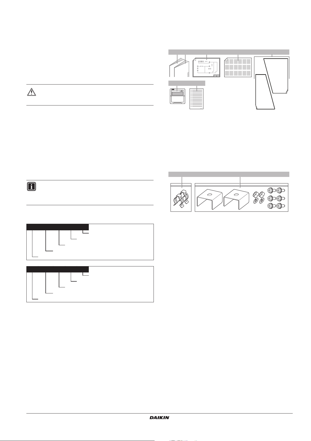
4. Accessories ............................................................................... 3
4.1. Accessories supplied with the domestic hot water
heat pump module EKHVWQ......................................................... 3
4.2. Accessories supplied with the domestic hot water
tank module EKHHS ......................................................................3
5. Overview....................................................................................4
5.1. Overview of the domestic hot water heat pump module ................ 4
5.2. Overview of the domestic hot water tank module........................... 4
5.3. Switchbox main components..........................................................5
5.4. Functional diagram .........................................................................5
6. Installation of the unit.................................................................6
6.1. Selecting an installation location .................................................... 6
6.2. Field piping .....................................................................................8
6.3. Inspecting and handling the unit .................................................... 8
6.4. Installing the indoor unit ................................................................. 9
7. Piping connection work............................................................10
7.1. Water piping work.........................................................................10
Water quality ................................................................................10
Checking the water circuit ............................................................ 10
Connecting the water circuit.........................................................11
Connect the pressure relief valve (field supply) and drain............11
Connect the drain pan..................................................................11
7.2. Precautions when connecting field piping and
regarding insulation......................................................................11
8. Charging water......................................................................... 11
8.1. Method for adding water............................................................... 11
9. Electrical wiring work ...............................................................12
9.1. Precautions on electrical wiring work........................................... 12
9.2. Internal wiring - Parts table ..........................................................12
9.3. System overview of field wiring .................................................... 13
Connection of the indoor unit power supply and
communication cable(s) ...............................................................13
Installation of the remote controller .............................................. 14
Connection to a benefit kWh rate power supply........................... 15
10. Start-up and configuration ....................................................... 16
10.1. Pre-operation checks ................................................................... 16
10.2. Field settings................................................................................17
Different domestic hot water tank operation modes.....................17
Procedure..................................................................................... 18
Detailed description...................................................................... 19
Field settings table .......................................................................22
11. Final check and test run........................................................... 23
11.1. Final check...................................................................................23
11.2. Test run ........................................................................................23
Displaying actual temperatures and actual water flow .................23
Procedure for domestic water heating.......................................... 23
12. Maintenance and service.........................................................23
12.1. Maintenance activities.................................................................. 24
12.2. Checks .........................................................................................24
12.3. Descaling......................................................................................25
13. Troubleshooting........................................................................ 25
13.1. General guidelines .......................................................................25
13.2. Opening the unit........................................................................... 25
13.3. General symptoms.......................................................................25
13.4. Error codes................................................................................... 26
14. Important information regarding the refrigerant used .............. 27
15. Disposal requirements ............................................................. 27
16. Unit specifications....................................................................27
16.1. Technical specifications EKHVWQ002AAV3................................27
16.2. Electrical specifications EKHVWQ002AAV3 ................................ 27
16.3. Specifications EKHHS200+260AA1V3 ........................................ 27
READ THESE INSTRUCTIONS CAREFULLY BEFORE
INSTALLATION. KEEP THIS MANUAL IN A HANDY
PLACE FOR FUTURE REFERENCE.
IMPROPER INSTALLATION OR ATTACHMENT OF
EQUIPMENT OR ACCESSORIES COULD RESULT IN
ELECTRIC SHOCK, SHORT-CIRCUIT, LEAKS, FIRE OR
OTHER DAMAGE TO THE EQUIPMENT. BE SURE ONLY
TO USE ACCESSORIES MADE BY DAIKIN WHICH ARE
SPECIFICALLY DESIGNED FOR USE WITH THE
EQUIPMENT AND HAVE THEM INSTALLED BY A
PROFESSIONAL.
ALL ACTIVITIES DESCRIBED IN THIS MANUAL SHALL
BE CARRIED OUT BY A LICENSED TECHNICIAN.
BE SURE TO WEAR ADEQUATE PERSONEL PROTECTION EQUIPMENT (PROTECTION GLOVES, SAFETY
GLASSES, ...) WHEN PERFORMING INSTALLATION,
MAINTENANCE OR SERVICE TO THE UNIT.
IF UNSURE OF INSTALLATION PROCEDURES OR USE,
ALWAYS CONTACT YOUR DAIKIN DEALER FOR ADVICE
AND INFORMATION.
THE UNIT DESCRIBED IN THIS MANUAL IS DESIGNED
FOR INDOOR INSTALLATION ONLY AND FOR AMBIENT
TEMPERATURES RANGING 2°C~35°C.
The English text is the original instruction. Other languages are
translations of the original instructions.
EKHVWQ002AAV3 + EKHHS200+260AA1V3
Domestic hot water heat pump
4PW65342-1A – 10.2010
Installation manual
1
Page 4
1. DEFINITIONS
1.1. Meaning of warnings and symbols
Warnings in this manual are classified according to their severity and
probability of occurrence.
DANGER
Indicates an imminently hazardous situation which, if not
avoided, will result in death or serious injury.
WARNING
Indicates a potentially hazardous situation which, if not
avoided, could result in death or serious injury.
CAUTION
Indicates a potentially hazardous situation which, if not
avoided, may result in minor or moderate injury. It may also
be used to alert against unsafe practices.
NOTICE
Indicates situations that may result in equipment or
property-damage accidents only.
INFORMATION
This symbol identifies useful tips or additional information.
Some types of danger are represented by special symbols:
Electric current.
Danger of burning and scalding.
1.2. Meaning of used terms
Installation manual:
Instruction manual specified for a certain product or application,
explaining how to install, configure and maintain it.
Operation manual:
Instruction manual specified for a certain product or application,
explaining how to operate it.
Maintenance instructions:
Instruction manual specified for a certain product or application,
which explains (if relevant) how to install, configure, operate and/or
maintain the product or application.
Dealer:
Sales distributor for products as per the subject of this manual.
Installer:
Technical skilled person who is qualified to install products as per the
subject of this manual.
User:
Person who is owner of the product and/or operates the product.
Service company:
Qualified company which can perform or coordinate the required
service to the unit.
Applicable legislation:
All international, European, national and local directives, laws,
regulations and/or codes which are relevant and applicable for a
certain product or domain.
Accessories:
Equipment which is delivered with the unit and which needs to be
installed according to instructions in the documentation.
Optional equipment:
Equipment which can optionally be combined to the products as per
the subject of this manual.
Field supply:
Equipment which needs to be installed according to instructions in
this manual, but which are not supplied by Daikin.
2. GENERAL SAFETY PRECAUTIONS
The precautions listed here are divided into the following four types.
They all cover very important topics, so be sure to follow them
carefully.
DANGER: ELECTRICAL SHOCK
Switch off all power supply before removing the switchbox
service panel or before making any connections or
touching electrical parts.
Do not touch any switch with wet fingers. Touching a switch
with wet fingers can cause electrical shock. Before
touching electrical parts, turn off all applicable power
supply.
To avoid electric shock, be sure to disconnect the power
supply 1 minute or more before servicing the electrical
parts. Even after 1 minute, always measure the voltage at
the terminals of main circuit capacitors or electrical parts
and, before touching, be sure that those voltages are
50 V DC or less.
When service panels are removed, live parts can easily be
touched by accident. Never leave the unit unattended
during installation or servicing when the service panel is
removed.
DANGER: DO NOT TOUCH PIPING AND INTERNAL
PA RT S
Do not touch the refrigerant piping, water piping or internal
parts during and immediately after operation. The piping
and internal parts may be hot or cold depending on the
working condition of the unit.
Your hand may suffer burns or frostbite if you touch the
piping or internal parts. To avoid injury, give the piping and
internal parts time to return to normal temperature or, if
you must touch them, be sure to wear protective gloves.
WARNING
■ Never directly touch any accidental leaking
refrigerant. This could result in severe wounds caused
by frostbite.
■ Do not touch the refrigerant pipes during and
immediately after operation as the refrigerant pipes
may be hot or cold, depending on the condition of the
refrigerant flowing through the refrigerant piping,
compressor, and other refrigerant cycle parts.
Your hands may suffer burns or frostbite if you touch
the refrigerant pipes. To avoid injury, give the pipes
time to return to normal temperature or, if you must
touch them, be sure to wear proper gloves.
CAUTION
Do not rinse the unit. This may cause electric shocks or
fire.
Installation manual
2
EKHVWQ002AAV3 + EKHHS200+260AA1V3
Domestic hot water heat pump
4PW65342-1A – 10.2010
Page 5
3. INTRODUCTION
4. ACCESSORIES
3.1. General information
Thank you for purchasing this unit.
The module EKHVWQ002AAV3 is the heat pump part of the
domestic hot water heat pump, the modules EKHHS200AA1V3 and
EKHHS260AA1V3 are the domestic hot water tank parts of the
domestic hot water heat pump. The domestic hot water tanks are
available in two different water capacities : 200 and 260 litre.
The unit is designed for floor standing indoor installation.
CAUTION
An EKHVWQ002AAV3 module can only be connected to
an EKHHS200AA1V3 or an EKHHS260AA1V3 module.
Floormounting kit EKFMHHSAA
The domestic hot water tank module EKHHS is intended to be
installed on top of the heat pump module EKHVW. In case this is not
possible the domestic hot water tank module can be installed next to
the heat pump module EKHVW in combination with a field installed
option EKFMHHSAA.
3.2. Scope of this manual
This installation manual describes the procedures for handling,
installing and connecting all modules of the domestic hot water heat
pump.
INFORMATION
Operation of the domestic hot water heat pump is
described in the domestic hot water heat pump operation
manual.
4.1. Accessories supplied with the domestic hot water heat pump module EKHVWQ
13 42
67
1 Installation manual
2 Operation manual
3 Wiring diagram
4 Unpacking instruction sheet
5 Sound bottom plate
6 Remote controller
7 Multilingual fluorinated greenhouse gases label
5
4.2. Accessories supplied with the domestic hot water tank module EKHHS
12
3.3. Model identification
EK HVWQ 002 AA V3
Series
Heating capacity
Domestic hot water heat pump module
European kit
EK HHS 200 AA1 V3
Series
Domestic hot water tank capacity
Domestic hot water tank module
European kit
1 Piping fixation clamps
2 Domestic hot water tank module fixation parts
1N~, 230 V, 50 Hz
1N~, 230 V, 50 Hz
EKHVWQ002AAV3 + EKHHS200+260AA1V3
Domestic hot water heat pump
4PW65342-1A – 10.2010
Installation manual
3
Page 6
5. OVERVIEW
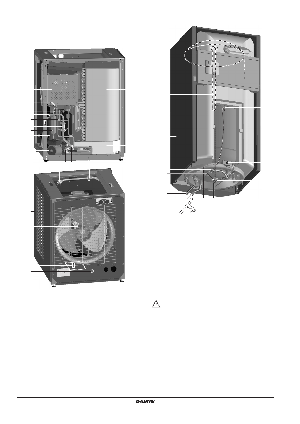
5.1. Overview of the domestic hot water heat pump module
5.2. Overview of the domestic hot water tank module
2
1
9
8
1
17
1
12
1
7
6
1 10 114 15
11
5
1
13
1 Temperature sensor (thermistor)
Temperature sensors determine the water and refrigerant
temperature at various points in the circuit.
2 Switch box
The switch box contains the main electronic and electrical
parts of the indoor unit.
3 Condensor
4 Evaporator
5 Fan motor and propeller
6 Pump
The pump circulates the water in the water circuit.
7 Compressor
8 Accumulator
9 Electronic expansion valve
10 Service port water circuit
11 Casing
12 Flow sensor
13 Drain pan socket
14 Water inlet connection from domestic hot water tank
15 Water outlet connection to domestic hot water tank
16 Sound bottom plate
17 Service port R410A
4
3
16
10
11
6
13
1
8
2
3+4
1 Hot water out connection
2 T-piece (field supply)
3 Pressure relief valve connection (field supply)
4 Pressure relief valve ( field supply)
5 Thermistor socket
6 Flow inlet connection from the heat pump module
7 Return outlet connection to the heat pump module
8 Cold water in connection
9 Thermistor
10 Anode
11 Casing
12 Thermal protector
The thermal protector is activated when the temperature
becomes too high.
13 Booster heater
14 Thermal fuse
CAUTION
This domestic hot water tank module can only be used with
an EKHVWQ indoor module.
5
9
12
7
14
Installation manual
4
EKHVWQ002AAV3 + EKHHS200+260AA1V3
Domestic hot water heat pump
4PW65342-1A – 10.2010
Page 7
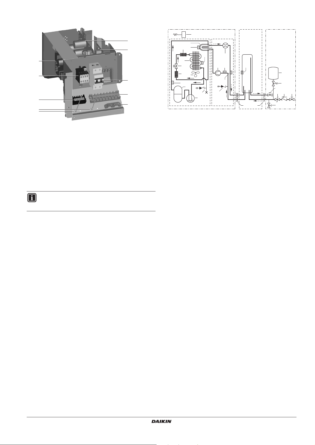
5.3. Switchbox main components
54
2 3
1
5.4. Functional diagram
3
2
1
8
7
4
5
6
6
1 Main PCB
The main PCB (Printed Circuit Board) controls the
functioning of the unit.
2 Filter PCB
3 Inverter PCB
4 Terminal block X2M
Main terminal block which allows easy connection of field
wiring for power supply.
5 Terminal block X3M
Field wiring terminal block for low voltage connections.
6 Strain relief for cables
7 Fuse for booster heater power supply
8 Booster heater contactor
INFORMATION
The electrical connection diagram can be found on the
inside of the switch box cover.
1
t >
24
23
7
8
27
25
6
9
8
10
26
11
13
12
1 Heat pump module (EKHVWQ*)
2 Heat pump module, refrigerant side
3 Heat pump module, water side
4 Domestic hot water tank (EKHHS*200, EKHHS*260)
5 Field istallation
(According to local and national regulations)
6 Air heat exhanger (evaporator)
7 Water heat exchanger (condensor)
8 Filter
9 Expansion valve (Y1E)
10 Fan with fan motor (M1F)
11 Compressor (M1C)
12 Accumulator
13 Service port 5/16"
14 Flow sensor (S1NF)
15 Pump (M1P)
16 Expansion vessel
17 Pressure relief valve
18 Pressure reducing valve
19 Non returning valve
20 Shut off valve
21 Drain valve
22 Quick coupling connection
23 Screw connection G 1/2" MBSP
24 Thermistor ambient temperature (R1T)
25 Thermistor evaporator temperature (R2T)
26 Thermistor discharge temperature (R3T)
27 Thermistor heat exchanger temperature (R4T)
28 Thermistor leaving water temperature (R5T)
29 Thermistor entering water temperature (R6T)
30 Thermistor domestic hot water tank (R7T)
151329
14
30
28
22
23
54
16
17
20
201918
21
EKHVWQ002AAV3 + EKHHS200+260AA1V3
Domestic hot water heat pump
4PW65342-1A – 10.2010
Installation manual
5
Page 8
6. INSTALLATION OF THE UNIT
6.1. Selecting an installation location
WARNING
■ Make sure to provide for adequate measures in order
to prevent that the indoor unit should be used as a
shelter by small animals.
■ Small animals making contact with electrical parts can
cause malfunctions, smoke or fire. Please instruct the
customer to keep the area around the unit clean.
The unit is to be placed in an indoor location that meets the following
requirements:
General
■ Installation shall be done by a licensed technician, the choice of
materials and installations shall comply with local and national
regulations.
■ The equipment is not intended for use in a potentially explosive
environment.
■ There is no danger of fire due to leakage of inflammable gas.
■ If the sound is measured under actual installation conditions, the
measured value will be higher than the sound pressure level
mentioned in the "Unit specifications" on page 27 due to
environmental noise and sound reflections. Choose the
installation location carefully and do not install in a sound
sensitive environment (e.g. living room, bedroom, ...).
■ Be sure that sufficient precautions are taken, in accordance with
relevant local and national regulations, in case of refrigerant
leakage.
Location requirements
■ The installation location is frost-free and indoors.
■ Take care that in the event of a water leak, water can not cause
any damage to the installation space and surroundings.
■ The foundation must be strong enough to support the weight of
both models.
The floor is flat to prevent vibrations and noise generation and to
have sufficient stability especially when the optional domestic
hot water tank is mounted on top of the unit.
■ Volume of installation location
During operation the heat pump module increases the domestic
water temperature by using the indoor stored heat. Typical
installation location for this product is a garage, cellar, technical
room, etc.
To have an optimum unit operation and to prevent a too big
temperature drop in the installation location, take the following
requirements for the installation location into account:
■ Minimum volume of the installation room
The heatpump operation stops whenever the indoor ambient
temperature becomes lower than 2°C (this can be adapted
by field setting [7-04]). After that, the electric heater in the
domestic hot water tank module will continue to heat up the
domestic hot water. This is a unit safety that prevents the
installation room to cool down further (preventing that e.g.
water piping in the installation room gets damaged) and
guarantees a sufficient comfort level in the form of sufficient
amount of domestic hot water.
To prevent this safety to occur frequently and to assure the
use of the electric heater as little as possible, the room size
must have a minimum volume (see figure below). All
depends on the outdoor temperature, the temperature
setpoint of the adjacent heated room and the insulation
properties of the walls. The volumes in the figure are valid for
an outdoor temperature of –10°C and a temperature setpoint
of the adjacent heated room of 16°C.
With this room volume, the heatpump can heat up 260 liters
domestic hot water from 10°C to 60°C.
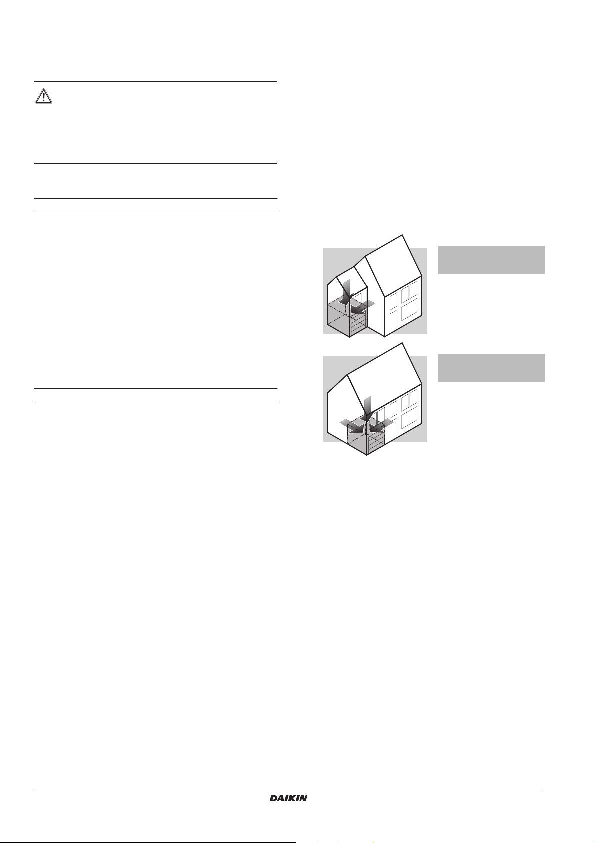
Garage included in house
One wall and ceiling of garage
are in contact with heated area
Minimum required
volume
Square footprint 25 m
Height 2.5 m
Garage included in house
Two walls and ceiling of garage
are in contact with heated area
Minimum required
volume
Square footprint 20 m
Height 2.5 m
When the installation room size does not match the minimum
requirement volume or if the walls between the installation
room and adjacent heated room have better insulation
properties than a single brick wall, additional heat sources
must be considered.
Examples of heat sources:
- if installed in a basement the ground surrounding the
basement will heat up the installation room temperature
- if installed in a garage, the heat of the cars engine
- natural ventilation via e.g. doors leading to the adjacent
heated rooms
- ventilation connection to a heated room
- other: washing machine, dryer
60 m
50 m
3
2
3
2
Installation manual
6
EKHVWQ002AAV3 + EKHHS200+260AA1V3
Domestic hot water heat pump
4PW65342-1A – 10.2010
Page 9
■ Humidity of the adjacent heated rooms
The room where the unit is installed will cool down.
Depending on the relative humidity temperature in the
adjacent room and the insulation property of the common
walls, condensation could occur on the wall.
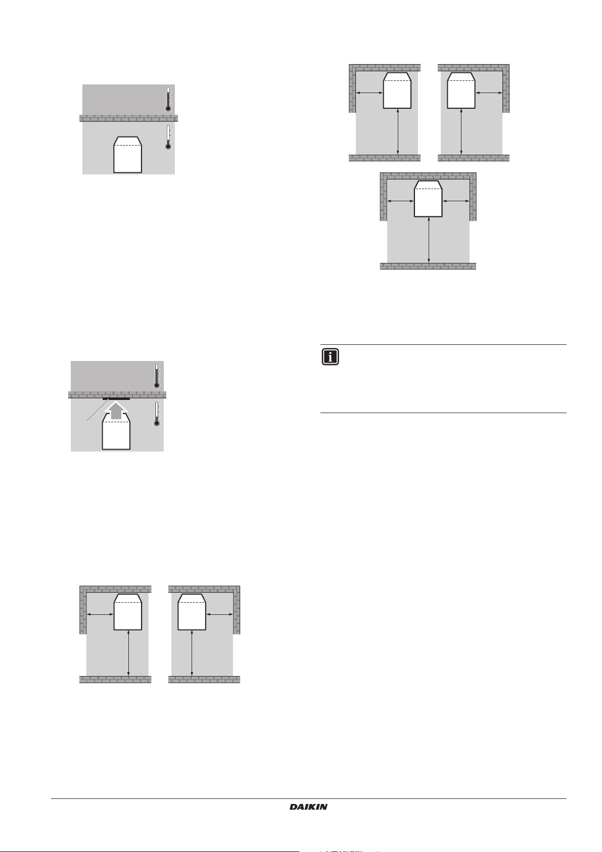
■ Installing near a wall or obstacle
When the unit is installed as mentioned in the figure below,
the performance and operation of the unit will be optimum.
C
≥150
B
≥150
A
A E.g. kitchen
B
B E.g. garage
If the relative humidity in the adjacent heated room is often
higher than 60% (e.g. bathroom) during the heating season
(when outdoor ambient temperature is lower than 15°C)
condensation could occur on the common walls. Relative
humidity levels of a living room normally do not exceed this
60%.
If this should be the case consider to limit the cool down of
the installation room by considering additional heat sources
(see above remarks).
■ Air blowing out
Depending on the operating conditions and the installation
condition, the cold air blown out at the back of the unit can cause
condensation or heat losses to surroundings.
In this case consider to locally insulate the wall on the unit side,
or install the heat pump module with the cold air blow out to an
(e.g.) outside wall.
A
A E.g. kitchen
B
D
C
B E.g. garage
C Insulation
D Cold air blow out
from heat pump
module
A
≥400
C
≥150
A
A Space required for switch box removal
B Space required for air intake
C Space required for air blow out to the left
≥400
A
B
≥500
≥400
Where a wall or other obstacle is not according to the figure
mentioned in "Installing near a wall or obstacle", follow the
installation guidelines below.
INFORMATION
If the unit cannot be installed according to the figure
mentioned in "Installing near a wall or obstacle", consider
to use flexible piping between the unit and the customer
water circuit. This could facilitate possible service jobs
where access to one of the sides is required.
Exampl
e: when water piping is situated in the blow out zone of
the unit depending on operating conditions and the water
temperature inside the piping this piping can condens. In this
case consider to insulate the water piping.
Depending on the operating conditions and the installation
condition the cold air blown out at the back of the unit can cause
heatlosses and even freezing up temperatures to e.g. non
insulated water piping located in this cold area! In this case
consider to insulate the water piping.
■ Required space around the unit
■ The space around the unit is adequate for servicing
B
≥150
AA
≥400
A Space required for switch box removal
B Left installation
C Right installation
C
≥150
≥400
EKHVWQ002AAV3 + EKHHS200+260AA1V3
Domestic hot water heat pump
4PW65342-1A – 10.2010
Installation manual
7
Page 10

Preferred installation locations
■ Garage or cellar with a heat producing source (for example a
washing machine or drier, a freezer, a hot boiler for space
heating or an other heat emitting source).
■ Cellar that will release heat from the floor.
■ Room with good insulation towards outside.
■ Room that needs to be dehumified.
Do nots
■ Do not install the unit in places often used as workplace.
In case of construction works (e.g. grinding works) where a lot of
dust is created, the unit must be shut down and covered.
■ Do not install the unit in places with high humidity (e.g.
bathroom) (maximum humidity (RH)=85%).
■ Do not install the unit where there is a mist of mineral oil, oil
spray or vapour for example a kitchen. Plastic parts may
deteriorate and cause them to fall out or water to leak.
■ Do not install the unit where corrosive gas, such as sulphurous
acid gas is produced. Corrosion of copper pipes or soldered
parts may cause the refrigerant to leak.
■ Do not install the unit where flammable gases may leak, where
carbon fiber or ignitable dust is suspended in the air or where
volatile flammables, such as thinner or gasoline are handled.
Such gases may cause of fire.
■ Do not install the unit where acidic or alkaline vapour is present.
■ Do not install the unit in places where water leaking from the unit
can cause damage to the location (e.g. in case of a blocked
drain pipe).
■ Do not install the unit near a bedroom and the like, so that the
operation noise will cause no trouble.
■ Do not place any objects or equipment on top of the unit (top
plate).
■ Do not climb, sit or stand on top of the unit.
■ Do no install in a room without any means of heating inside that
is not connected to an other room with a heating source (for
example a garden house).
6.2. Field piping
■ Provisions at the cold water inlet of the domestic hot water tank
- To avoid back siphonage it is advised to install a non return
valve on the cold water inlet in accordance with local and
national regulations.
- It is advised to install a pressure reducing valve on the cold
water inlet in accordance with local and national regulations.
- Provide a connection for a pressure relief valve on the cold
water inlet.
- Install an expansion vessel on the cold water inlet in
accordance with local and national regulations.
- Install a drain device on the cold water connection on the
domestic hot water tank.
WARNING
Do not install any valves between the domestic hot water
tank module and the pressure relief valve/expansion
vessel.
■ It is advised to provide a shut off valve before and after the unit.
This will facilitate maintenance on the domestic hot water circuit.
■ It is recommended to install a shut off valve on the cold water
inlet. Close this shut off valve during periods of abscense to
avoid damage to the surroundings in case water should leak.
■ During operation and depending on operation conditions the
heat pump module collects condens water in the drain pan at the
bottom of the unit. Make sure to provide a proper drain
connection to this drain pan.
■ It is advised to avoid long runs of piping between the unit and the
hot water end point (shower, bath, ...) and to avoid dead ends.
■ In accordance with local and national regulations it may be
necessary to install thermostatic mixing valves.
■ The installation must be in accordance with local and national
regulations and may require additional hygienic installation
measures.
■ If required by relevant local and
national regulations, connect a
recirculation pump in between the hot
water end point and the cold water in
connection of the domestic hot water
tank.
6.3. Inspecting and handling the unit
■ At delivery, the unit must be checked and any damage must be
reported immediately to the carrier claims agent.
■ Bring both models as close as possible to its final installation
position in its original package in order to prevent damage
during transport.
■ Unpack the models completely according to the instructions
mentioned on the unpacking instructions sheet.
■ Check if all accessories (see "Accessories" on page 3) are
enclosed.
Installation manual
8
EKHVWQ002AAV3 + EKHHS200+260AA1V3
Domestic hot water heat pump
4PW65342-1A – 10.2010
Page 11

6.4. Installing the indoor unit
1
1
■ Unpack the EKHVWQ according to unpacking instruction sheet.
■ Place the heat pump module in the appropriate installation
location as close as possible to the installation location.
■ Level the heat pump module to a stable position using the
levelling feet. The maximum allowed deviation from a horizontal
position is 1°.
1°
■ Unpack the EKHHS according to the unpacking instructions
delivered with the unit.
■ Perform the electrical wiring work as described in the chapter
"Electrical wiring work" on page 12.
■ Connect the system to the water circuit as described in the
chapter "Piping connection work" on page 10.
■ Fill the system with water as described in the chapter "Charging
water" on page 11.
■ To make the casing completely sealed, plug the knockout holes
with putty or insulation materials (to be prepared on-site).
■ Perform the pre-operation checks as described in the chapter
"Start-up and configuration" on page 16.
■ Close the unit
1 Put the sound bottom plates at the bottom of the unit.
3 Align the side panels of the heat pump module with the
domestic hot water tank module side panels.
4 Fix the front panel to the domestic hot water tank module.
1
2
2x
1
2x
2
2 Close the decoration panels.
1
2
2x
2
EKHVWQ002AAV3 + EKHHS200+260AA1V3
Domestic hot water heat pump
4PW65342-1A – 10.2010
Installation manual
9
Page 12

5 Fix the front panel of the heat pump module.
1
7. PIPING CONNECTION WORK
1
7.1. Water piping work
Water quality
Before continuing the installation of the unit, check the following
points
■ Domestic hot water quality must be according to EU directive
98/83 EC. Specifically take care that:
2
2x
- Chloride content maximum 250 mg/l
- Sulphate content maximum 250 mg/l
- Combination of both maximum 300 mg/l
The unit must not be used with water from a private supply.
■ In known hard water regions, precautions should be taken to
prevent lime scale formation in hot water.
■ For safety reasons, it is not allowed to add any kind of glycol to
the water circuit.
■ To avoid stagnation of water, it is important that the storage
capacity of the domestic hot water tank meets the daily
consumption of domestic hot water.
In cases where during longer periods of time there is no
consumption of hot water, the equipment must be flushed with
fresh water before usage.
The disinfection function provided on the equipment is specified
in the operation manual of the unit.
Checking the water circuit
The units are equipped with a water inlet and water outlet for
connection to a water circuit. This circuit must be provided by a
licensed technician and must comply with all relevant European and
national regulations.
Before continuing the installation of the unit, check the following
points:
■ The maximum allowed unit water pressure is 10 bar.
■ The maximum water temperature at the unit outlet is 75°C.
Take care that the components installed in the field piping can
withstand this water temperature.
DANGER
The maximum water temperature to the unit must be
limited to 55°C.
■ Drain taps must be provided at all low points of the system to
permit complete drainage of the circuit during maintenance.
One drain valve in the indoor unit is provided to drain the water
from the indoor unit water system. Only perform this draining
when all the water of the domestic hot water tank is already
drained.
■ Take care that the components installed in the field piping can
withstand the water pressure and temperature.
■ Always use materials which are compatible with the water used
in the domestic water circuit. In the unit water circuit copper,
stainless steel and brass is used.
WARNING
Never use Zn coated parts in the water circuit. Excessive
corrosion of these parts may occur as copper piping is
used in the unitís internal water circuit.
Installation manual
10
EKHVWQ002AAV3 + EKHHS200+260AA1V3
Domestic hot water heat pump
4PW65342-1A – 10.2010
Page 13

Connect the domestic hot water tank module to the heat pump module
Refer to the unpacking instruction sheet.
■ If the domestic hot water tank module is put next to the unit,
installing of the EKFMHMSAA kit is necessary. Refer to the
manual of that kit.
■ Make sure to check if the speed setting of the pump is set in
position III if the domestic hot water tank module is mounted on
top of the heat pump module.
Connecting the water circuit
Water connections must be made. The location of the water inlet
connection and the water outlet connection on the unit is shown in
the chapter 5.2. "Overview of the domestic hot water tank module" on
page 4.
WARNING
Be careful not to deform the unit
piping by using excessive force when
connecting the piping. Deformation of
the piping can cause the unit to
malfunction. Use two wrenches as
shown in the figure.
Connect the drain pan
During operation and depending on operation conditions the heat pump
module collects condens water in the drain pan at the bottom of the unit.
Make sure to provide a proper drain connection to this drain pan.
CAUTION: Requirements to drain piping
■ The drain piping must be positioned away from any
electrical components.
■ The drainpipe must terminate in a safe, visible position
without forming any risk to persons in the vicinity.
■ All drain pipe work must be installed in a continuously
downward direction and in a frost-free environment. It
must be left open to the atmosphere.
7.2. Precautions when connecting field piping and
regarding insulation
The complete water circuit, inclusive all piping, must be insulated to
reduce loss of heat.
If the indoor ambient temperature is higher than 30°C and the
humidity is higher than RH 80% then the thickness of the insulation
materials should be at least 20 mm in order to avoid condensation on
the surface of the insulation.
If air, moisture or dust gets in the water circuit, problems may occur.
Therefore, always take into account the following when connecting
the water circuit:
■ Use clean pipes only.
■ Hold the pipe end downwards when removing burrs.
■ Cover the pipe end when inserting it through a wall so that no
dust and dirt enter.
■ Use a good thread sealant for the sealing of the connections.
■ When using non-brass metallic piping, make sure to insulate
both materials from each other to prevent galvanic corrosion.
■ Because brass is a soft material, use appropriate tooling for
connecting the water circuit. Inappropriate tooling will cause
damage to the pipes.
Connect the pressure relief valve (field supply) and drain
■ In accordance with relevant local and national regulations, a field
supplied pressure relief valve with an opening pressure of
maximum 10 bar must be connected to the pressure relief valve
connection.
■ Make sure to provide a proper drain for the field supplied
pressure relief valve to avoid any water coming into contact with
electrical parts.
CAUTION: Requirements to discharges
■ Discharge piping, drain valves, etc. must be
positioned away from any electrical components.
■ All discharge pipe work must be installed in a
continuously downward direction and in a frost-free
environment. It must be left open to the atmosphere.
8. CHARGING WATER
8.1. Method for adding water
1 Connect the water supply to the unit
2 Open each hot water tap in turn to expel air from the system
pipe work
3 Open the field installed hot water shut off valve
4 Open the field installed cold water supply valve
5 Close all hot water taps after all air is expelled
6 Check for leaks
7 Manually operate the field supplied pressure relief valve to
ensure free water flow
CAUTION
Immediately after installation, the domestic hot water tank
must be flushed with fresh water. This procedure must be
repeated at least once a day for the first 5 consecutive
days after installation.
DANGER of burning and scalding
The discharge pipe must terminate in a safe, visible
position without forming any risk to persons in the vicinity.
EKHVWQ002AAV3 + EKHHS200+260AA1V3
Domestic hot water heat pump
4PW65342-1A – 10.2010
Installation manual
11
Page 14

9. ELECTRICAL WIRING WORK
9.1. Precautions on electrical wiring work
WARNING
■ A main switch or other means for disconnection,
having a contact separation in all poles, must be
incorporated in the fixed wiring in accordance with
relevant local and national regulations.
■ Switch off the power supply before making any
connections.
■ Use only copper wires.
■ All field wiring and components must be installed by a
licensed electrician and must comply with relevant
European and national regulations.
■ Be sure to install the required fuses as mentioned on
the electrical wiring diagram.
■ The field wiring must be carried out in accordance
with the wiring diagram supplied with the unit and the
instructions given below.
■ Never squeeze bundled cables and make sure that it
does not come in contact with the piping and sharp
edges.
Make sure no external pressure is applied to the
terminal connections.
■ Be sure to use a dedicated power supply. Never use a
power supply shared by another appliance.
■ Be sure to establish an earth. Do not earth the unit to
a utility pipe, surge absorber, or telephone earth.
Incomplete earth may cause electrical shock.
■ Be sure to install an earth leakage protector in
accordance with relevant local and national
regulations. Failure to do so may cause electrical
shock.
When installing the earth leakage protector make sure
that it is compatible with the inverter (resistant to high
frequency electrical noise) to avoid unnecessary
opening of the earth leakage protector.
■ As this unit is equipped with an inverter, installing a
phase advancing capacitor not only will deteriorate
power factor improvement effect, but also may cause
capacitor abnormal heating accident due to highfrequency waves. Therefore, never install a phase
advancing capacitor.
■ Be sure that after installation work all the rubber
bushings are put back in place to protect the wires
from touching sharp edges.
9.2. Internal wiring - Parts table
Refer to the internal wiring diagram supplied with the unit. The
abbreviations used are listed below.
Switch box components list
A1P.................. Main PCB
A2P.................. User interface PCB
A3P.................. Filter PCB
A4P.................. Inverter PCB
C6~C119 ......... Capacitor (A4P)
DS2,DS3 .........DIP switch (A1P)
E1H ................. Electric heater element
F1B.................. Fuse
F1T.................. Thermal fuse
F1U,F2U.......... Fuse (T, 3.15 A, 250 V) (A*P)
F3U.................. Fuse (20 A, 250 V) (A3P)
HAP................. PCB LED (A1P)
K1.................... Changeover contact (A3P)
K1E.................. Electronic expansion valve
K1M................. Contactor backup heater
K*R.................. PCB relay (A1P)
M1C................. Compressor
M1F ................. Fan motor
M1P................. Pump
Q1DI................ Earth leakage protector (field supply)
Q1L.................. Compressor overheat protector
Q2L.................. Thermal protector
R1L.................. Reactor
R1T.................. Ambient temperature sensor
R2T.................. Evaporator temperature sensor
R3T.................. Discharge temperature sensor
R4T.................. Condensing temperature sensor
R5T.................. Leaving water temperature sensor
R6T.................. Entering water temperature sensor
R7T.................. Domestic hot water tank temperature sensor
S1L.................. Flow sensor
S1S.................. Benefit kWh power rate signal (field supply)
T1R.................. Diode bridge (A4P)
T2R,T3R.......... Power module (A4P)
V1C~V7C ........Ferrite core
X1M~X3M ....... Terminal strp
X1Y~X7Y......... Connector
Z1F.................. Noise filter
CAUTION: For V3 models only
■ Equipment complying with EN/IEC 61000-3-12
■ This equipment complies with EN/IEC 61000-3-11
provided that the system impedance Z
or equal to Z
at the interface point between the
max
is less than
sys
user's supply and the public system. It is the
responsibility of the installer or user of the equipment
to ensure, by consultation with the distribution network
operator if necessary, that the equipment is connected
only to a supply with a system impedance Z
. Z
than or equal to Z
(a) European/International Technical Standard setting the limits for harmonic
currents produced by equipment connected to public low-voltage systems with
input current >16 A and ≤75 A per phase.
(b) European/International Technical Standard setting the limits for voltage changes,
voltage fluctuations and flicker in public low-voltage supply systems for
equipment with rated current ≤75 A.
Installation manual
max
max
=0.43 Ω.
12
sys
(a)
less
(b)
EKHVWQ002AAV3 + EKHHS200+260AA1V3
Domestic hot water heat pump
4PW65342-1A – 10.2010
Page 15

9.3. System overview of field wiring
Field wiring on the unit side is to be made on the terminal block inside
the switch box. To gain access to the terminal blocks, remove the
switch box service panel. Refer to the unit switch box cover for
instructions how to remove this panel and gain access to the inside of
the switch box.
INFORMATION
The electrical connection diagram can be found on the
inside of the switchbox cover Install the power supply cable
and communication cable at least 1 meter away from
televisions or radios to prevent image interference or noise.
Depending on the radio waves, a distance of 1 meter may
not be sufficient to eliminate the noise.
Connection of the indoor unit power supply and communication cable(s)
Cable requirements
Required
number of
Item Description
1 HV Power supply 2+GND Refer to the nameplate
2 LV Remote controller
(P1/P2)
3 LV Domestic hot water
tank thermistor
4 LV Benefit kWh rate power
supply signal
5 HV Booster heater 2+GND Minimum cable section
6 HV Booster heater safeties 2 Minimum cable section
HV = High voltage
LV = Low voltage
conductors
2 Minimum cable section
2 This device and
2 Minimum cable section
Maximum running
current
2
0.75 mm
connection cable are
delivered with the
domestic hot water tank
module
2
0.75 mm
2
0.75 mm
2
0.75 mm
Procedure
1 Open the unit as described in "Opening the unit" on page 25.
2 Open the switch box cover as shown in the figure.
2x
3 Using the appropriate cable, connect the power supply and
communication cable(s) to the appropriate terminals as shown
on the wiring diagram and according to the figure below.
X3M
1210 1413911
123 4
X2M
LN
CAUTION
Select all cables and wire sizes in accordance with relevant
local and national regulations.
DANGER
After finishing the electric work, confirm that each electric
part and terminal inside the electric parts box is connected
securely.
9101112
X3M
-t
°
R7T
*KHHS(200/260)AAV3
AB C D
X2M
1234
123
Q2L
F1T
*KHHS(200/260)AAV3
A2P
P1
P2
User Interface
14
13
S1S
E1H
4
E
PE
Q1DI
1~50 Hz 220-240 VAC
LN
L
power supply
ABC D E
LV HV
NOTICE
When wiring, route the cable bundles that are outside
the unit away from each other by at least 25 mm in
order to avoid receiving electric noise (external
noise).
N
EKHVWQ002AAV3 + EKHHS200+260AA1V3
Domestic hot water heat pump
4PW65342-1A – 10.2010
Installation manual
13
Page 16

4 Fix the cables with cable ties to the cable tie mountings to
ensure strain relief and to make sure that it does not come in
contact with the piping and sharp edges. Never squeeze
bundled cables.
Note: only relevant field wiring is shown in the figure.
3x
3 Wire the remote controller.
4
3
X3M
11
2
P1P2
3
1 Unit
2 Rear part of the digital controller
3 Front part of the digital controller
There is no polarity, so the 2 wires can be switched.
CAUTION
■ When wiring, run the wiring away from the power
supply wiring in order to avoid receiving electric noise
(external noise).
■ Peel the shield for the part that has to
pass through the inside of the digital
controller case ( l ).
5 Close the switch box cover following the instructions described
in "Opening the unit" on page 25 in reverse order.
Installation of the remote controller
The unit is equipped with a remote controller offering user-friendly
way to set up, use and maintain the unit. Before operating the remote
controller, follow this installation procedure.
INFORMATION
The wiring for connection is not included.
NOTICE
The remote controller, delivered in a kit, has to be mounted
indoors on the domestic hot water tank module.
1 Remove the front part of the remote controller.
Insert a slotted screwdriver into the slots (1)
in the rear part of the remote controller, and
remove the front part of the remote
controller.
1
2 Fasten the remote controller as shown in the figure.
1
4 Reattach the upper part of the remote controller.
DANGER
Be careful not to pinch the wiring when attaching.
First begin fitting from the clips at the
bottom.
1
2
Installation manual
14
2x
NOTICE
Be careful not to distort the shape of the lower part of
the remote controller by over tightening the mounting
screws.
EKHVWQ002AAV3 + EKHHS200+260AA1V3
Domestic hot water heat pump
4PW65342-1A – 10.2010
Page 17

Connection of the domestic hot water tank module to the heat pump module
■ Booster heater and safety (A)
■ Tank thermistor (B)
■ Remote controller (C)
1
2
C
B
Connection to a benefit kWh rate power supply
Electricity companies throughout the world work hard to provide
reliable electric service at competitive prices and are often authorized
to bill clients at benefit rates. E.g. time-of-use rates, seasonal rates,
Wärmepumpentarif in Germany and Austria, ...
This equipment allows for connection to such benefit rate power
supply delivery systems.
Consult with the electricity company acting as provider at the site
where this equipment is to be installed to know whether it is
appropriate to connect the equipment in one of the benefit kWh rate
power supply delivery systems available, if any.
When the equipment is connected to such benefit kWh rate power
supply, the electricity company is allowed to:
■ interrupt power supply to the equipment for certain periods of
time;
■ demand that the equipment only consumes a limited amount of
electricity during certain periods of time.
The indoor unit is designed to receive an input signal by which the
unit switches into forced off mode. At that moment, the unit
compressor and the heater will not operate.
WARNING
For a benefit kWh rate power supply like illustrated
below as type 1
During the period that the benefit kWh rate is active and
power supply is continuous, then stand-by power
consumption of the inverter PCB is possible.
CAUTION
For a benefit kWh rate power supply like illustrated
below as types 2 or 3
A
3x
A
If during benefit kWh rate power supply the power supply is
shut.
■ This power supply interruption should not be longer
than 2 hours, otherwise the real time clock of the
controller will be reset.
■ During power supply interruption, the controller
display will be blank.
C
B
EKHVWQ002AAV3 + EKHHS200+260AA1V3
Domestic hot water heat pump
4PW65342-1A – 10.2010
Installation manual
15
Page 18

Possible types of benefit kWh rate power supply
Possible connections and requirements to connect the equipment to
such power supply are illustrated in the figure below:
1
2
[D-01]=1
LN
1
S2S
43
1
2
[D-01]=2
LN
1
S2S
43
INFORMATION
When connecting the equipment to a benefit kWh rate
power supply, change field setting [D-01].
INFORMATION
If the benefit kWh rate power supply is of the type that
power supply is not interrupted, the unit will be forced to
off.
When the benefit kWh rate signal is sent, the centralised
control indicator e will appear to indicate that the benefit
kWh rate is active.
LN
2
1
2
3
1
2
3
3
1 Benefit kWh rate power supply box
2 Receiver controlling the signal of the electricity company
3 Power supply to unit
4 Voltage free contact to indoor unit
When the unit is connected to a benefit kWh rate power supply, the
voltage free contact of the receiver controlling the benefit kWh rate
signal of the electricity company must be connected to clamps 5 and
6 of X3M (as illustrated in the figure above).
When parameter [D-01]=1 at the moment that the benefit kWh rate
signal is sent by the electricity company, that contact will open and
the unit will go in forced off mode
When parameter [D-01]=2 at the moment that the benefit kWh rate
signal is sent by the electricity company, that contact will close and
the unit will go in forced off mode
Type 1
This type of benefit kWh rate power supply is not interrupted.
Type 2
This type of benefit kWh rate power supply is interrupted after elapse
of time.
Type 3
This type of benefit kWh rate power supply is interrupted immediately.
S2S
LN
S2S
43
4
4
X3M5 6
A1P
X40A
1
2
1
2
3
(1)
.
(2)
.
LN
2
S2S
43
LN
3
S2S
4
10. START-UP AND CONFIGURATION
The unit should be configured by the installer to match the installation
environment (outdoor climate, installed options, etc.) and user
expertise.
CAUTION
It is important that all information in this chapter is read
sequentially by the installer and that the system is
configured as applicable.
INFORMATION
When a power failure occurred and the power returns to
the unit, the system will automatically restore it's settings
and restart.
10.1. Pre-operation checks
DANGER
Switch off the power supply before making any
connections.
After the installation of the unit, check the following:
1 Field wiring
Make sure that the field wiring has been carried out according to
the instructions described in the chapter "Electrical wiring work"
on page 12, according to the wiring diagrams and according to
European and national regulations.
2 Fuses and protection devices
Check that the fuses and other locally installed protection
devices are of the size and type specified in the chapter
"Technical specifications EKHVWQ002AAV3" on page 27. Make
sure that neither a fuse nor a protection device has been
bypassed.
3 Earth wiring
Make sure that the earth wires have been connected properly
and that the earth terminals are tightened.
4 Internal wiring
Visually check the switch box and the inside of the unit on loose
connections or damaged electrical components.
5 Installation
Check that the unit is properly installed, to avoid abnormal
noises and vibrations when starting up the unit.
6 Damaged equipment
Check the inside of the unit on damaged components or
squeezed pipes.
(1) When the signal is released again, the voltage free contact will close and
the unit will restart operation. It is therefore important to leave the auto
restart function enabled. Refer to "[3] Miscellaneous" on page 19.
(2) When the signal is released again, the voltage free contact will open and
the unit will restart operation. It is therefore important to leave the auto
restart function enabled. Refer to "[3] Miscellaneous" on page 19.
Installation manual
16
EKHVWQ002AAV3 + EKHHS200+260AA1V3
Domestic hot water heat pump
4PW65342-1A – 10.2010
Page 19

7 Refrigerant leak
Check the inside of the unit on refrigerant leakage. If there is a
refrigerant leak, call your local dealer.
Do not touch any refrigerant which has leaked out of refrigerant
piping connections.
This may result in frostbite.
8 Water leak
Check the inside of the unit on water leakage. In case there is a
water leakage close the water inlet and water outlet shut-off
valves and call your local dealer.
9 Power supply voltage
Check the power supply voltage on the local supply panel. The
voltage must correspond to the voltage on the identification label
of the unit.
Once all checks are fulfilled, the unit must be closed, only then can
the unit be powered up. When the power supply to the indoor unit is
turned on, "88" is displayed on the remote controller during its
initialization, which might take up to 30 seconds. During this process
the remote controller can not be operated.
10.2. Field settings
The unit should be configured by the installer to match the user
demand. Thereto, a number of so called field settings are available.
These field settings are accessible and programmable through the
user interface on the unit.
Each field setting is assigned a 3-digit number or code, for example
[2-01], which is indicated on the user interface display. The first digit
[2] indicates the 'first code' or field setting group. The second and
third digit [013] together indicate the 'second code'.
A list of all field settings and default values is given in the "Field
settings table" on page 22. In this list we provided for 2 columns to
register the date and value of altered field settings at variance with
the default value.
A detailed description of each field setting is given under "Detailed
description" on page 19.
NOTICE
Field setting [2] depends on the relevant local and national
regulations.
Before changing these settings, the new values shall be
confirmed by the installer and/or shall be according to the
local and national regulations.
Different domestic hot water tank operation modes
To understand the field setting possibilities explained in the following
chapters, understand that different domestic hot water tank operation
modes are possible.
■ Powerfull operation
■ If the P button is pressed, the heat pump module heats up
the domestic hot water tank as fast as possible to a
predefined setpoint. This means that the inverter compressor
frequency will be higher then in normal operation mode and
that sound level and power consumption can be higher.
This mode might be usefull when exceptional high hot water
consumption depletes all the available domestic hot water
and hot water is required.
■ Depending on settings, simultaneous heat pump operation
and booster heater operation can occur.
INFORMATION
The unit increases the domestic hot water temperature by
using the indoor stored heat.
The powerful mode might not function properly when the
room ambient temperature is too low.
■ Disinfection operation
■ This mode will disinfect the domestic hot water tank by
periodically heating the domestic water to a high temperature. This can be required for e.g. legionella prevention.
■ This mode is enabled by default.
Refer to the chapter "Detailed description" on page 19 for a
detailed description how to set one or more field settings.
- [0-01] Set point: Disinfection water temperature to be
reached (see figure "[2] Disinfection operation" on page 19).
- [2-00] Operation interval: day of the week at which the
domestic water should be heated.
- [2-01] Status: defines whether the disinfection function is
turned ON (1) or OFF (0).
- [2-02] Start time: time at which the disinfection operation is
started.
- [2-04] Duration: time period defining how long the disinfection
set point temperature should be maintained.
Even when the unit is in OFF mode, disinfection operation can
work (depending on field setting [2-03]).
■ Reheat operation
This mode will prevent the domestic hot water from cooling down
lower than a certain temperature. When enabled the unit will
heat up the domestic hot water tank when the reheat minimum
value is reached. This heating will continue until the reheat
maximum temperature is reached.
This means that the unit can heat up continuously and e.g. not
limited to night time operation. This reheat operation is only valid
when schedule timer operation is enabled and not active.
■ Automatic operation
■ This operation mode contains a learning function to predict
the daily hot water consumption. It will calculate and predict
the optimum tank temperature setpoint based on the user
tapping history.
Enabling this operation mode will keep the tank temperature
as low as possible but to a temperature which guarantees a
high comfort level.
■ The advantage of a low tank temperature setpoint are :
- Reduced heatlosses
- Better unit performance, the lower the tank temperature the
better the heat up coefficient of performance (COP).
- Lower electric power consumption
■ Refer to the operation manual for a detailed description.
EKHVWQ002AAV3 + EKHHS200+260AA1V3
Domestic hot water heat pump
4PW65342-1A – 10.2010
Installation manual
17
Page 20

■ Domestic water heating modes
T
AB
CD
E
F
G
H
J
A Normal or automatic domestic hot water tank operation
(if activated)
B Reheat operation (if activated)
C Disinfection operation (if activated)
D Powerful operation
Field settings
E Disinfection operation temperature
F Normal or automatic domestic hot water tank temperature
G Powerful temperature set point
H Reheat maximum water temperature
J Reheat minimum water temperature
t Time
T Domestic hot water tank temperature
Procedure
To change one or more field settings, proceed as follows.
To change field settings [2] to [F]
(to be performed only by the installer)
1 Press the z button for a minimum of 5 seconds to enter FIELD
SET MODE.
2 Press the z button for a minimum of 10 seconds to enter FIELD
SET MODE 2.
The $ icon (3) will be displayed. The current selected field
setting code is indicated ; (2), with the set value displayed to
the right - (1).
t
3 Press the wi button to select the appropriate field setting
first code.
4 Press the wj button to select the appropriate field setting
second code.
5 Press the pfi button and pfj button to change
the set value of the select field setting.
6 Save the new value by pressing the pr button.
7 Repeat step 2 through 4 to change other field settings as
required.
8 When finished, press the z button to exit FIELD SET MODE.
INFORMATION
■ Changes made to a specific field setting are only
stored when the pr button is pressed. Navigating to
a new field setting code or pressing the z button will
discard the change made.
■ The field settings are grouped by their field setting first
code.
For example field settings [0-00], [0-01], [0-02] and
[0-03] are defined as group "0".
3
1
2
To change field settings [0] and [1]
(to be performed by the installer and the customer)
1 Press the z button for a minimum of 5 seconds to enter FIELD
SET MODE.
The $ icon (3) will be displayed. The current selected field
setting code is indicated ; (2), with the set value displayed to
the right - (1).
2 Press the wi button to select the appropriate field setting
first code.
3 Press the wj button to select the appropriate field setting
second code.
4 Press the pfi button and pfj button to change
the set value of the select field setting.
5 Save the new value by pressing the pr button.
6 Repeat step 2 through 4 to change other field settings as
required.
7 When finished, press the z button to exit FIELD SET MODE.
INFORMATION
■ Before shipping, the set values have been set as
shown under "Field settings table" on page 22.
■ When exiting FIELD SET MODE 2, "88" may be
displayed on the remote controller LCD while the unit
initializes itself.
NOTICE
When running through the field settings you may notice
that there are some more field settings as there are
mentioned in the "Field settings table" on page 22. These
field settings are not applicable and may not be
changed!
WARNING
■ It is the installers responsibility to make sure no
unwanted situations can occur (e.g. too high water
temperatures towards hot water taps, etc.).
■ It is the installers responsibility to make sure the water
circuit is well balanced (e.g. when a domestic hot
water request occurs, there will be sufficient flow
towards hot water taps)
Installation manual
18
EKHVWQ002AAV3 + EKHHS200+260AA1V3
Domestic hot water heat pump
4PW65342-1A – 10.2010
Page 21

Detailed description
[0] Different operation modes
■ [0-00] Powerfull operation mode temperature set point
■ [0-01] Disinfection operation mode tempeature set point
■ [0-02] Temperature setpoint: reheat minimum temperature
■ [0-03] Temperature setpoint: reheat maximum temperature
■ [0-04] Reheat function enabled/disabled: defines whether the
reheat operation is turned ON(1) or OFF(0)
[1] Automatic domestic hot water tank temperature set point
calculation
■ [1-00] Renewal time for set point calculation
The automatic temperature set point calculation is done on a
daily basis. The algorithm calculates for each day of the week an
optimum domestic hot water tank temperature set point. To
calculate this temperature setpoint, the learning function
monitors per 24 hours the domestic water heating demand and
based on this demand calculates the optimum set point for that
specific day of the week.
This field setting contains the starting time for the 24 hours
monitoring period.
This field setting must be set preferably after the main heating
up of the domestic water of the day has finished.
For example: If in schedule timer operation mode the schedule
timer was set from 22 h until 6 h, the renewal time should be set
at 6 h.
■ [1-01] Minimum automatic temperature set point
If required the minimum temperature set point for the automatic
set point calculation can be adjusted. If, for example,
considerable heatlosses are expected on the field piping
between the hot water tap and the domestic hot water heat
pump, this temperature set point can be usefull.
■ [1-02] Maximum automatic temperature set point
The maximum temperature that the automatic set point can
reach.
However, if this value is set on a temperature higher than 60°C,
that maximum temperature will only be reached when field
setting [3-02] is set to 1 (ON). If the setting of [3-02] is 0, the
maximum temperature will be 60°C (only heating up by heat
pump) ignoring higher set temperatures.
[2] Disinfection operation
The disinfection function disinfects the domestic hot water tank by
periodically heating the domestic hot water to a specific temperature.
NOTICE
The disinfection function field settings must be configured
by the installer according to local and national regulations.
■ [2-00] Operation interval: day of the week at which the domestic
water should be heated.
■ [2-01] Status: defines whether the disinfection function is turned
ON(1) or OFF(0)
■ [2-02] Start time: time at which the disinfection operation is
started.
■ [2-03] Status: defines whether the disinfection function is turned
ON(1) or OFF(0) during standby operation. If for example, during
holiday the customer puts the unit in stand-by mode by pressing
the Y button but still wants the disinfection mode to be active,
the setting of [2-03] must be ON(1).
■ [2-04] Interval: time period defining how long the disinfection
temperature set point should be maintained.
[3] Miscellaneous
■ [3-00] Auto restart
When power returns after a power supply failure, the auto restart
function reapplies the user interface settings at the time of the
power supply failure.
INFORMATION
It is therefore recommended to leave the auto restart
function enabled.
If auto restart is disabled after a power supply failure, the system
will restart in OFF-mode. Press the v button to start heating
up the water again.
Note that with the function disabled the schedule timer will not
be activated when power returns to the unit after a power supply
failure. Press the pr button to enable the schedule timer again.
INFORMATION
If the benefit kWh rate power supply is of the type that
power supply is interrupted, then always allow the
auto restart function.
■ [3-01] User permission level
The remote controller can be programmed to make certain
buttons and functions unavailable for the user. There are 2
permission levels defined.
The following table shows which functions are accessable with
permission level 2 and with permission level 3.
Permission
level 2 level 3
Domestic water heating operation
ON/OFF
Powerful operation Operable Not available
Setting the domestic hot water
temperature
Quiet mode ON/OFF Operable Not available
Auto adaptive set point operation
ON/OFF
Setting the clock Not available Not available
Programming the schedule timer Not available Not available
Schedule timer operation ON/OFF Operable Not available
Field settings Not available Not available
Error code display Not available Not available
Displaying actual temperatures and
water flow
Changing unit of temperature
(°C/°F)
Changing user permession level Operable Operable
Operable Operable
Operable Operable
Operable Not available
Not available Not available
Operable Operable
By default no level is defined so all buttons and functions are
operable.
The actual permission level is determined by field setting. For
permission level 2, set field setting [3-01] to 2, for permission
level 3, set field setting [3-01] to 3.
Once the field setting is set, the chosen permission level is not
yet active. Enabling the selected permission level is done by
simultaneously pressing buttons pi and pj immediately
followed by simultaneously pressing buttons s and P, and
keeping all 4 buttons pressed for at least 5 seconds. Note that
no indication on the remote controller is given. After the
procedure the blocked buttons will not be available anymore.
Deactivating the selected permission level is done on the same
way.
EKHVWQ002AAV3 + EKHHS200+260AA1V3
Domestic hot water heat pump
4PW65342-1A – 10.2010
Installation manual
19
Page 22

■ [3-02] Status: defines whether temperatures above 60°C can be
selected (1) or not (0).
INFORMATION
■ The maximum domestic hot water tank
temperature by heat pump operation is limited to
60°C. A higher temperature set point is only
possible by electric booster heater operation.
■ When this field setting is not activated, the
booster heater will still work if the ambient
temperature drops below the value set in [7-04].
This is the backup mode of the domestic hot
water heat pump.
■ [3-03] Status: defines whether the heat up can continue (1) or
not (0) when the requested temperature set point is not reached
during the programmed schedule timer operation. The p icon is
blinking in case the heat up can not continue ([3-03]=0).
In case the reheat function is enabled, the p icon will stop
blinking when the reheat operation has finished.
[4] Miscellaneous
■ [4-03] Simultanuous operation of booster heater and heatpump
■ [4-03]=0 Simultanuous operation of the electric booster
heater and heat pump is not allowed.
■ [4-03]=1 Simultanuous operation of the booster heater and
heat pump is only allowed during quiet mode. During quiet
operation the heat pump operation sound is reduced by
reducing the compressor frequency. This influences the
heating capacity and increases the heat up cycle time.
If required the electric booster heater can assist to heat up
the domestic hot water tank to shorten the heat up cycle
time.
■ [4-03]=2 Simultanuous operation of the booster heater and
heat pump is only allowed during powerful operation mode.
The powerful operation mode is considered as an
exceptional operation mode. If required during powerful
operation the electric booster heater can assist to heat up the
domestic hot water tank.
■ [4-03]=3 Allows the simultanuous operation of electric
booster heater and heat pump during quiet and powerful
operation.
[6] Miscellaneous
[6-00] and [6-01]: The 'DT (temperature difference) for heat pump
domestic water heating mode' field settings determine the
temperatures at which heating of the domestic hot water by the heat
pump will be started (i.e., the heat pump ON temperature) and
stopped (i.e., the heat pump OFF temperature).
When the domestic hot water temperature drops below the heat
pump ON temperature (T
), heating of the domestic hot water by
HP ON
the heat pump will be started. As soon as the domestic hot water
temperature reaches the heat pump OFF temperature (T
HP OFF
) or
the user set point temperature (TU), heating of the domestic hot water
by the heat pump will be stopped.
The heat pump OFF temperature, and the heat pump ON
temperature, and its relation with field settings [6-00] and [6-01] are
explained in the illustration below.
■ [6-00] Start: temperature difference determining the heat pump
ON temperature (T
). See illustration.
HP ON
■ [6-01] Stop: temperature difference determining the heat pump
OFF temperature (T
T
<60°C
T(°C)
T
T
HP MAX
T
HP OFF
T
HP ON
U
60
45
40
U
TU = 45°C
[6-01] = 0°C
[6-00] = 5°C
T
HP MAX
= T
T
U
HP OFF
T
HP ON
User set point temperature (as set on the user interface)
Maximum domestic hot water tank temperature at sensor in
domestic hot water tank by heat pump operation
Heat pump OFF temperature
Heat pump ON temperature
). See illustration.
HP OFF
[6-00]
■ [6-02] Booster heater economical timer: determines when the
booster heater can start after the heat pump has started
operating. This setting is only meaningfull when the
simultanuous operation of the booster heater and heat pump is
allowed ([4-03] is not set to 0).
■ [6-03] Powerful mode priority: determines the priority when quiet
operation mode and powerful operation mode are active at the
same moment.
[6-03]
priority
0 OFF Normal Quiet
1 OFF Normal Quiet
Powerful
setting
ON Powerful Normal Quiet
ON Powerful Powerful Powerful Powerful
OFF Level 1 Level 2 Level 3
Quiet mode setting
level 1
level 1
Quiet
level 2
level 1
Quiet
level 2
Quiet
level 3
Quiet
level 2
Quiet
level 3
Installation manual
20
If [6-03] is set to 1, powerful operation mode has priority over
quiet operation mode.
■ [6-04] Quiet mode level: defines the level of noise reduction.
There are 3 levels of noise reduction during operation in quiet
mode, where level 3 is the most quiet mode.
EKHVWQ002AAV3 + EKHHS200+260AA1V3
Domestic hot water heat pump
4PW65342-1A – 10.2010
Page 23

[7] Miscellaneous
■ [7-01] DT for booster heater
When the domestic water is heated and the domestic hot water
set point temperature (as set by the user) has been reached, the
booster heater will stop until the domestic hot water temperature
drops a few degrees below the set point temperature, i.e. the
booster heater ON temperature. The booster heater will start
heating up the domestic water again. These degrees are
specified by the domestic hot water step length field setting.
Correct setting prevents the booster heater from repeatedly
turning on and off (i.e. chattering) to maintain the domestic hot
water set point temperature.
■ [7-01] Domestic hot water step length: temperature
difference below the domestic hot water set point
temperature before the booster heater is turned on again.
T
DHW
T
70
U
68
T
BH ON
T
60
HP MAX
T
55
HP ON
HP
10
5
BH Booster heater
HP Heat pump
T
BH ON
T
HP MAX
T
DHW
T
Booster heater ON temperature (TU–[7-01])
Maximum domestic hot water tank temperature at sensor in
domestic hot water tank by heat pump operation
Domestic hot water temperature
User set point temperature (as set on the user interface)
U
t Time
[7-01]
BH
=70°C
T
U
[7-01] = 2°
C
t
WARNING
If the high water temperature can be a potential risk for
human injuries, a mixing valve (field supply) shall be
installed at the hot water outlet connection of the domestic
hot water tank. This mixing valve shall secure that the hot
water temperature at the hot water tap never rise above a
set maximum value. This maximum allowable hot water
temperature shall be selected according to local and
national regulations.
■ [7-03] Not applicable
■ [7-04] T-ambient adaption: this field setting allows to adapt the
minimum allowed temperature in the installation room for heat
pump operation.
WARNING
It is very important that this value is not set to a
temperature that can cause damage to the installation
room!
It must be set in a way so that condensation does not
occur on the cold walls of the adjacent heated room.
[8] Automatic set point calculation
■ [8-00] Set point (weekdays): starting temperature for automatic
set point calculation during weekdays.
■ [8-01] Set point (week-end): starting temperature for automatic
set point calculation during week-end.
NOTICE
Because the domestic hot water demand is not known
from the start and to avoid comfort problems this
should be set to the customer estimated consumption
set point.
■ [8-02] Initial city water temperature
To be able to start calculation of the automatic set point, [8-02]
should be set to the current city water temperature when the unit
is started. The outdoor temperature will influence the city water
temperature, making it colder during winter time and warmer
during summer time.
■ [8-03] Reset demand: when this field setting is set to 1 and
power is reset, the automatic set point calculation is reset and
calculation will start all over again. This setting is used when
there is a permanent change in the user domestic hot water
consumption pattern.
When power is reset, initialisation is executed and this field
setting will automatically be set to 0.
■ [8-04] Domestic hot water tank volume: depending on which
domestic hot water tank is used with the heat pump, the correct
volume must be set:
■ [8-04]=0 when the tank volume is 260 litres (EKHHS260)
■ [8-04]=1 when the tank volume is 200 litres (EKHHS200)
NOTICE
If the setting of [8-04] is not set correctly, customers
might have a hot water shortage when using the auto
adaptive set point. So it is important to set this
correctly!
[D] Benefit kWh rate power supply
Benefit kWh rate power supply
[D-01] Unit connection to benefit kWh rate power supply: Defines
whether or not the unit is connected to a benefit kWh rate power
supply.
■ If [D-01]=0, the unit is connected to a normal power supply
(default value).
■ If [D-01]=1 or 2, the unit is connected to a benefit kWh rate
power supply. In this case the wiring requires specific installation
like explained in "Connection to a benefit kWh rate power
supply" on page 15.
When parameter [D-01]=1 at the moment that the benefit kWh
rate signal is sent by the electricity company, that contact will
open and the unit will go in forced off mode
(1)
.
When parameter [D-01]=2 at the moment that the benefit kWh
rate signal is sent by the electricity company, that contact will
close and the unit will go in forced off mode
(2)
.
[E] Unit information readout
■ [E-00] Readout of the software version (example: 23)
■ [E-01] Readout of the EEPROM version (example: 23)
■ [E-02] Readout of the unit model identification (example: 11)
WARNING
If the value of [7-04] is set lower than 2°C, the correct
unit operation can not be guaranteed and damage to
the unit can occur.
EKHVWQ002AAV3 + EKHHS200+260AA1V3
Domestic hot water heat pump
4PW65342-1A – 10.2010
(1) When the signal is released again, the voltage free contact will close and
the unit will restart operation. It is therefore important to leave the auto
restart function enabled. Refer to "[3-00] Auto restart" on page 19.
(2) When the signal is released again, the voltage free contact will open and
the unit will restart operation. It is therefore important to leave the auto
restart function enabled. Refer to "[3-00] Auto restart" on page 19.
Installation manual
21
Page 24

Field settings table
First
Second
code
code
0 Different operation modes
1 Automatic domestic hot water tank temperature set point calculation
2 Disinfection operation
3 Miscellaneous
4 Miscellaneous
6 Miscellaneous
7 Miscellaneous
8 Automatic setpoint calculation
D Benefit kWh rate power supply/Local shift value weather dependent
E Unit information readout
Setting name
00 Powerfull operation mode temperature set point
01 Disinfection operation mode tempeature set point
02 Temperature setpoint: reheat minimum
temperature
03 Temperature setpoint: reheat maximum
temperature
04 Status: defines whether the reheat operation is
turned ON(1) or OFF(0)
00 Renewal time for set point calculation
01 Mnimum automatic temperature set point
02 Maximum automatic temperature set point
00 Operation interval
01 Status
02 Start time
03 Status
04 Interval
00 Auto restart
01 User permission level
02 Status
03 Status
03 Simultanuous operation of booster heater and
heatpump
04 Not applicable. Do not change the default value.
00 Start
01 Stop
02 Booster heater economical timer
03 Powerful mode priority
04 Quiet mode level
01 Domestic hot water step length
02 Not applicable. Do not change the default value.
03 Not applicable. Do not change the default value.
04 T-ambient
00 Set point (weekdays)
01 Set point (week-end)
02 Initial city water temperature
03 Reset demand
04 Domestic hot water tank volume
01 Benefit kWh rate power supply
00 Readout of the software version
01 Readout of the EEPROM version
02 Readout of the unit model identification
Installer setting at variance with default value
Default
value
40 35~50 1 °C
60 55~75 1 °C
40 35~75 1 °C
45 35~75 1 °C
0 (OFF) 0/1 1 —
6:00 0:00~23:30 0:30 hour
42 35~75 1 °C
60 35~75 1 °C
Fri
1 (ON) 0/1 1 —
23:00 0:00~23:00 1:00 hour
0 (OFF) 0/1 1 —
32 5~60 1 minute
1 (ON) 0/1 1 —
3 2/3 1 —
0 (OFF) 0/1 1 —
0 (OFF) 0/1 1 —
0 0/1/2/3 1 —
1
10 2~20 1 °C
0 0~10 1 °C
0 0~95 5 minute
1 (ON) 0/1 1 —
1 1/2/3 1 —
2 2~40 1 °C
3
0
2 –25~+10 1 °C
45 35~75 1 °C
50 35~75 1 °C
15 0~30 1 °C
0 (OFF) 0/1 1 —
0 (260 l) 0/1) 1 —
0 0/1/2 1 —
— Read only — —
— Read only — —
— Read only — —
Range Step UnitDate Value Date Value
Mon~Sun
All
——
Installation manual
22
EKHVWQ002AAV3 + EKHHS200+260AA1V3
Domestic hot water heat pump
4PW65342-1A – 10.2010
Page 25

11. FINAL CHECK AND TEST RUN
12. MAINTENANCE AND SERVICE
11.1. Final check
Before switching on the unit, read the following:
■ When the complete installation and all necessary settings have
been carried out, be sure that all panels of the unit are closed. Is
this not the case, inserting your hand through the remaining
openings can cause serious injury due to electrical and hot parts
inside the unit.
■ The service panel of the switch box may only be opened by a
licensed electrician for maintenance purposes.
11.2. Test run
The installer is obliged to verify correct operation of the unit after
installation. Therefore a test run must be performed according to the
procedures described below. At any time it is possible to check
correct unit operation.
INFORMATION
During the first start up of the unit (the first 48 hours of
compressor running), it might happen that the noise level
of the unit is higher than mentioned in the technical
specifications. This is not an abnormal event.
Displaying actual temperatures and actual water flow
1 Push the ba button for 5 seconds.
The b icon and the outgoing water temperature from the heat
pump are displayed. The icon l is flashing.
2 Use the pi and pj buttons to display:
• The ambient temperature (u icon is flashing).
Indication code 001.
• The temperature of the incoming water to the heat pump.
Indication code 002.
• The temperature of the outgoing water from the heat pump.
Indication code 003.
• The actual domestic hot water tank temperature (w icon is
flashing).
Indication code 004.
• The actual water flow in the water circuit (é icon is flashing).
Indication code 005.
3 Push the ba button again to leave this mode. If no button is
pressed, the remote controller leaves the display mode after 10
seconds.
In order to ensure optimal availability of the unit, a number of checks
and inspections on the unit and the field wiring have to be carried out
at regular intervals.
DANGER
■ Each inspection has to be carried out by your local
Daikin technician and not by the user.
■ Do not touch water pipes immediately after operation
as the pipes may be hot. Your hand may suffer burns.
To avoid injury, give the piping time to return to normal
temperature or be sure to wear proper gloves.
To execute the maintenance activities as mentioned below,
■ it is required to remove the front decoration panel of the heat
pump module.
2x
(to take away the front decoration panel, remove the 2 bottom
screws.)
Procedure for domestic water heating
1 Check the domestic hot water tank temperature through the
remote controller read-out mode. See "Displaying actual
temperatures and actual water flow" on page 23.
2 Push the Y.
3 Set the water temperature water to a high set point. Make sure
the schedule timer icon p is not displayed.
The w icon will appear.
4 Keep the unit operating for 20 minutes and check the domestic
hot water tank temperature through the remote controller again.
5 The operation will stop if the tank storage temperature has been
reached.
EKHVWQ002AAV3 + EKHHS200+260AA1V3
Domestic hot water heat pump
4PW65342-1A – 10.2010
Installation manual
23
Page 26

■ it is required to remove the front decoration panel of the
domestic hot water tank module,
12.2. Checks
The described checks must be executed at least once a year by
qualified personnel.
1 Field supplied pressure relief valve
■ Check for correct operation of the pressure relief valve.
■ Check that the connected discharge piping still complies to
requirements stated in the chapter "Connect the pressure
relief valve (field supply) and drain" on page 11.
2 If a field supplied pressure reducing valve is installed
Depending on local water conditions, annual inspection of the
valve may be necessary
3 If a field supplied expansion relief valve or expansion vessel is
installed
Depending on local water conditions, annual inspection of the
valve or expansion vessel may be necessary.
4 Indoor unit switchbox
■ First remove the front decoration panel of the heat pump
module and then the front panel of the tank module.
2x
(to take away the front decoration panel, remove the 2 bottom
screws and then unhitch the panel.)
12.1. Maintenance activities
DANGER: ELECTRIC SHOCK
■ Before carrying out any maintenance or repair activity,
always switch off the circuit breaker on the supply
panel, remove the fuses or open the protection
devices of the unit.
■ Do not touch live parts for 10 minutes after the power
supply is turned off because of high voltage risk.
■ Please note that some sections of the electric
component box are hot.
■ Make sure you do not touch a conductive section.
■ Do not rinse the unit. This may cause electric shocks
or fire.
NOTICE: Play it safe!
Touch a metal part by hand (such as the stop valve) in
order to eliminate static electricity and to protect the PCB
before performing service.
2
2x
1
2x
Installation manual
24
■ Carry out a thorough visual inspection of the switch box and
look for obvious defects such as loose connections or
defective wiring.
EKHVWQ002AAV3 + EKHHS200+260AA1V3
Domestic hot water heat pump
4PW65342-1A – 10.2010
Page 27

5 Checking for leaks
Carry out a thorough visual inspection of the heat pump and
tank module and check for water leaks.
6 Pump speed
Make sure the pump speed is set into position III. Check if the
water flow is within range (between 5 and 6 l/min.). Refer to
"Displaying actual temperatures and actual water flow" on
page 23 how to access these values.
7 Drain connection
Make sure no dirt is blocking the drain connection at the back of
the unit.
13. TROUBLESHOOTING
This section provides useful information for diagnosing and correcting
certain troubles which may occur in the unit.
This troubleshooting and related corrective actions may only be
carried out by your local Daikin technician.
13.1. General guidelines
Before starting the troubleshooting procedure, carry out a thorough
visual inspection of the unit and look for obvious defects such as
loose connections or defective wiring.
12.3. Descaling
Depending on the water quality and set temperature, scale can
deposit on the heat exchanger inside the heat pump module and can
restrict heat transfer. If descaling of the heat exchanger is requested
a warning message will apear on the remote controller.
- A first message will appear when the water flow drops below
3 l/min. The unit will continue to work but an indication (error
code 7E) is already given.
- If the water flow continues to drop below 1 l/min., the unit will
stop and error code 7H will be shown. The system must be
restarted manually and corrective action must be taken.
DANGER
When using means for descaling, it must be ensured that
the water quality remains compliant with the requirements
stated in "Water quality" on page 10.
For descaling details refer to the service manual.
12.4. Draining
Follow the next steps to drain the domestic hot water tank:
1 Switch off the power supply.
2 Close the field installed cold water supply valve.
3 Open the hot water taps.
4 Open the field installed drain valve.
DANGER: Electric shock
When carrying out an inspection on the switch box of the
unit, always make sure that the main switch of the unit is
switched off.
When a safety device was activated, stop the unit and find out why
the safety device was activated before resetting it. Under no
circumstances safety devices may be bridged or changed to a value
other than the factory setting. If the cause of the problem can not be
found, call your local dealer.
13.2. Opening the unit
Refer to "Maintenance and service" on page 23 how to open the unit.
13.3. General symptoms
Symptom 1: The unit is turned on (Y LED is lit) but the unit is not
heating as expected
POSSIBLE CAUSES CORRECTIVE ACTION
The temperature setting is not
correct.
The water flow is too low.
Capacity shortage Check if the unit is not installed in a
Check the controller set point.
• Check that all shut-off valves of the
water circuit are completely open.
• Make sure there is no air in the
system (purge air).
• Make sure that the field installed
expansion vessel is not broken.
too hot location (>35°C) or a too cold
location (<2°C).
Symptom 2: Pump is making noise (cavitation)
POSSIBLE CAUSES CORRECTIVE ACTION
There is air in the system. Purge air.
Water pressure at pump inlet is too
low.
Symptom 3: The water pressure relief valve opens
POSSIBLE CAUSES CORRECTIVE ACTION
The field installed expansion vessel
is broken.
Check that the setting of the
pressure of the field installed
pressure reducing valve is correct.
Replace the expansion vessel.
EKHVWQ002AAV3 + EKHHS200+260AA1V3
Domestic hot water heat pump
4PW65342-1A – 10.2010
Installation manual
25
Page 28

Symptom 4: The water pressure relief valve leaks
POSSIBLE CAUSES CORRECTIVE ACTION
Cold water inlet pressure. Check the pressure reducing valve.
The field installed pressure relief
valve is not functioning properly.
Check for correct operation of the
pressure relief valve by turning the
red knob on the valve counter
clockwise:
• If you do not hear a clacking sound,
contact your local dealer.
• In case the water keeps running out
of the unit, close both the water inlet
and outlet shut-off valves first and
then contact your local dealer.
Dirt is blocking the water pressure
relief valve outlet.
Check for correct operation of the
pressure relief valve by turning the
red knob on the valve counter
clockwise:
• If you do not hear a clacking sound,
contact your local dealer.
• In case the water keeps running out
of the unit, close both the water inlet
and outlet shut-off valves first and
then contact your local dealer.
Symptom 5: Dirty water
POSSIBLE CAUSES CORRECTIVE ACTION
Dirty water Flush or clean the domestic hot
water tank after periods of standstill.
It could occur that particles in the
water deposit on the bottom of the
tank. If this deposit layer becomes
thick enough it could enter the hot
water outlet and contaminate the hot
water.
Symptom 6: The user interface displays "
n" when pressing
certain buttons
POSSIBLE CAUSES CORRECTIVE ACTION
The current permission level is set to
a level that prevents using the
pressed button.
Change the "user permission level"
field setting [0-00], see "Field
settings" in the operation manual.
Symptom 7: No water flow from hot taps
POSSIBLE CAUSES CORRECTIVE ACTION
The main water supply is off. Check that all shut off valves of the
water circuit are completely open.
The strainer is blocked (eg. stainer of
hot water tap).
The field installed cold water inlet
Turn off the water supply, remove
and clean the strainer.
Check and refit as required.
pressure reducing valve is not fitted
properly.
Symptom 8: Water from hot taps is cold
POSSIBLE CAUSES CORRECTIVE ACTION
The thermal cut-out located in the
domestic hot water tank module has
operated
• Check and find the cause of tripping
and then reset button.
• Check if the thermistor is correctly
installed in the thermistor socket of
the heat pump module.
Procedure: remove front panel and
insulation, replace or fix the sensor.
The heat pump is not operating. Check the heat pump module
operation. Refer to the manual
delivered with the unit.
If any faults are suspected, contact
your local dealer.
Symptom 9: Intermittent water discharge
POSSIBLE CAUSES CORRECTIVE ACTION
Thermal control failure (water will be
Contact your local dealer.
hot).
The field installed expansion vessel
Replace the expansion vessel.
is broken.
13.4. Error codes
When a safety device is activated, the user interface LED will be
flashing, and an error code will be displayed.
A list of all errors and corrective actions can be found in the table
below.
Reset the safety by pushing the Y button.
In case this procedure for resetting the safety is not successful,
contact your local dealer.
Error
code
Failure cause Corrective action
80 Inlet water temperature
thermistor failure (inlet water
thermistor broken)
81 Outlet water temperature
thermistor failure (outlet water
temperature sensor broken)
7E Scale accumulating error This is a first indication that
7H Flow failure (water flow too low
or no water flow at all, minimum
required water flow is 1 l/min)
A1 PCB defective (A1P) Contact your local dealer.
A5 Too high refrigerant temperature
(measured by R4T)
AC Booster heater thermal protector
is open
C4 Heat exchanger thermistor
failure (heat exchanger
temperature sensor broken)
E1 PCB defective (A3P, A4P) Contact your local dealer.
E5 Overload activation of
compressor
E6 Compressor start up error Check that the unit is operating
E7 Fan lock failure (fan is locked) Check if the fan is not obstructed
E8 Too high input current error Contact your local dealer.
EC Domestic hot water temperature
too high (>80°C)
F3 Too high discharge temperature Contact your local dealer.
H0 Compressor system sensor
abnormality
H6 Position sensor abnormality Contact your local dealer.
Contact your local dealer.
Contact your local dealer.
descaling the unit will be
required. The unit however will
continue to provide hot water.
Contact your local dealer.
• Check that the unit is operating
within its operating range (refer
to "Disposal requirements" on
page 27).
• Also refer to "Charging water" on
page 11.
• Make sure there is no air in the
system (purge air).
• Check on the manometer that
there is sufficient water pressure.
The water pressure must be
>1 bar (water is cold).
• Make sure that the expansion
vessel is not broken.
• Check that the pump fuse (FU2)
and PCB fuse (FU1) are not
blown.
• Descale the system.
Contact your local dealer.
• Check if pump speed selection is
at position III.
Contact your local dealer.
Reset the thermal protector
(refer to 5.2. "Overview of the
domestic hot water tank module"
on page 4 for the location of the
thermal protector).
Contact your local dealer.
Check that the unit is operating
within its operating range (refer
to "Disposal requirements" on
page 27).
Contact your local dealer.
within its operating range (refer
to "Disposal requirements" on
page 27).
Contact your local dealer.
by dirt. If the fan is not
obstructed, contact your local
dealer.
• Check that the contactor of the
electric booster heater is not
short circuited.
• Check that the domestic hot
water thermistor is giving the
correct read out.
Contact your local dealer.
Installation manual
26
EKHVWQ002AAV3 + EKHHS200+260AA1V3
Domestic hot water heat pump
4PW65342-1A – 10.2010
Page 29

Error
code
Failure cause Corrective action
H9 Ambient temperature thermistor
failure (ambient thermistor is
broken)
HC Domestic hot water tank
thermistor failure
Contact your local dealer.
Contact your local dealer.
J3 Discharge pipe thermistor failure Contact your local dealer.
J6 Aircoil thermistor frost detection
failure
Contact your local dealer.
L3 Electric component failure Contact your local dealer.
L4 Electric component failure Contact your local dealer.
L5 Electric component failure Contact your local dealer.
P4 Electric component failure Contact your local dealer.
U0 Refrigerant failure (due to
refrigerant leak)
Contact your local dealer.
U2 Main circuit voltage failure Contact your local dealer.
U4 Communication failure Contact your local dealer.
U5 Communication failure Contact your local dealer.
UA Communication failure Contact your local dealer.
14. IMPORTANT INFORMATION REGARDING THE
REFRIGERANT USED
16. UNIT SPECIFICATIONS
16.1. Technical specifications EKHVWQ002AAV3
Nominal capacity
Casing material
Dimensions H x W x D
Weight
• with packaging
• without packaging
Connections
• water inlet/outlet
• water drain
Pump
• type
• no. of speed
Sound pressure level
(a)
Internal water volume
Operation range - water side
Operation range - ambient air
• domestic hot water
(a) At 1 m in front of the unit (free field condition)
(b) Temperatures above 60°C are achieved by booster heater.
(c) field setting
16.2. Electrical specifications EKHVWQ002AAV3
(kW)
(mm)
(kg)
(kg)
(dBA)
(°C)
(°C)
2.5
Pre-coated sheet metal
730 x 600 x 595
153
144
Quick coupling
drain valve
AC motor
position III
47 dBA
(l)
1
35~75
+2~+35
(b)
(c)
This product contains fluorinated greenhouse gases covered by the
Kyoto Protocol. Do not vent gases into the atmosphere.
Refrigerant type: R410A
(1)
value: 1975
GWP
(1)
GWP = global warming potential
INFORMATION
National implementation of EU regulation on certain
fluorinated greenhouse gases may require to provide the
appropriate official national language on the unit.
Therefore, an additional multilingual fluorinated
greenhouse gases label is supplied with the unit.
Sticking instructions are illustrated on the backside of that
label.
15. DISPOSAL REQUIREMENTS
Dismantling of the unit and treatment of parts must be done in
accordance with relevant local and national legislation.
Phase 1N~
Frequency
(Hz)
50
Voltage range
• minimum
• maximum
(V)
(V)
220
240
Voltage tolerance –10%/+6%
Maximum running current
Recommended field fuse
(A)
(A)
17.4
20
16.3. Specifications EKHHS200+260AA1V3
EKHHS200 EKHHS260
Storage capacity
Material Stainless steel
Overall dimensions H x W x D
Connections G 1/2" MBSP
Inspection opening
Weight (empty)
Mounting On top of EKHVWQ002AAV3
Maximum pressure domestic
hot water tank
Maximum primary working
pressure (heating side)
Maximum tempreature
domestic hot water
Booster heater
• Power supply
• Running current
• Capacity
(a) MBSP = Male British Standard Pipe
(b) For floor standing next to the heat pump module, the EKFMHHSAA kit is needed.
(l)
(mm)
(mm)
(kg)
(bar)
(bar)
(°C)
200 260
1235 x 600 x 695 1510 x 600 x 695
Wrench 41
57 66
10
10
75
230 V 50 Hz 1~
(A)
(kW)
7
1.5
(a)
(b)
EKHVWQ002AAV3 + EKHHS200+260AA1V3
Domestic hot water heat pump
4PW65342-1A – 10.2010
Installation manual
27
Page 30

4PW65342-1A 10.2010
Copyright 2010 Daikin
 Loading...