

Daikin EHVH04S18E*6V, EHVH04S23E*6V, EHVH08S18E*6V, EHVH08S23E*6V, EHVH08S18E*9W Installer reference guide
...
Installer reference guide
Daikin Altherma 3 R F
ERGA04EAV3(A)
ERGA06EAV3(A)
ERGA08EAV3(A)
EHVH04S18E*6V
EHVH04S23E*6V
EHVH08S18E*6V
EHVH08S23E*6V
EHVH08S18E*9W
EHVH08S23E*9W
EHVX04S18E*3V
EHVX04S18E*6V(G)
EHVX04S23E*3V
EHVX04S23E*6V(G)
EHVX08S18E*6V(G)
EHVX08S23E*6V(G)
EHVX08S18E*9W
EHVX08S23E*9W

Table of contents
Table of contents
1 General safety precautions 6
1.1 About the documentation .............................................................................................................................................. 6
1.1.1 Meaning of warnings and symbols ................................................................................................................ 6
1.2 For the installer............................................................................................................................................................... 7
1.2.1 General ........................................................................................................................................................... 7
1.2.2 Installation site ............................................................................................................................................... 8
1.2.3 Refrigerant — in case of R410A or R32.......................................................................................................... 9
1.2.4 Water .............................................................................................................................................................. 10
1.2.5 Electrical ......................................................................................................................................................... 11
2 About the documentation 13
2.1 About this document ...................................................................................................................................................... 13
2.2 Installer reference guide at a glance .............................................................................................................................. 14
3 Specific installer safety instructions 15
3.1 Instructions for equipment using R32 refrigerant ......................................................................................................... 18
4 About the box 20
4.1 Overview: About the box ................................................................................................................................................ 20
4.2 Outdoor unit ................................................................................................................................................................... 20
4.2.1 To unpack the outdoor unit ........................................................................................................................... 20
4.2.2 To handle the outdoor unit ............................................................................................................................ 21
4.2.3 To remove the accessories from the outdoor unit........................................................................................ 21
4.3 Indoor unit ...................................................................................................................................................................... 22
4.3.1 To unpack the indoor unit .............................................................................................................................. 22
4.3.2 To remove the accessories from the indoor unit .......................................................................................... 22
4.3.3 To handle the indoor unit............................................................................................................................... 22
5 About the units and options 24
5.1 Overview: About the units and options.......................................................................................................................... 24
5.2 Identification ................................................................................................................................................................... 24
5.2.1 Identification label: Outdoor unit .................................................................................................................. 24
5.2.2 Identification label: Indoor unit ..................................................................................................................... 25
5.3 Combining units and options.......................................................................................................................................... 25
5.3.1 Possible options for the outdoor unit ............................................................................................................ 25
5.3.2 Possible options for the indoor unit............................................................................................................... 26
5.3.3 Possible combinations of indoor unit and outdoor unit................................................................................ 28
6 Application guidelines 29
6.1 Overview: Application guidelines ................................................................................................................................... 29
6.2 Setting up the space heating/cooling system ................................................................................................................ 29
6.2.1 Single room ..................................................................................................................................................... 30
6.2.2 Multiple rooms – OneLWT zone ................................................................................................................... 34
6.2.3 Multiple rooms – TwoLWT zones.................................................................................................................. 38
6.3 Setting up an auxiliary heat source for space heating ................................................................................................... 40
6.4 Setting up the domestic hot water tank......................................................................................................................... 43
6.4.1 System layout – Integrated DHW tank........................................................................................................... 43
6.4.2 Selecting the volume and desired temperature for the DHW tank .............................................................. 43
6.4.3 Setup and configuration – DHW tank ............................................................................................................ 45
6.4.4 DHW pump for instant hot water .................................................................................................................. 45
6.4.5 DHW pump for disinfection ........................................................................................................................... 45
6.5 Setting up the energy metering...................................................................................................................................... 46
6.5.1 Produced heat ................................................................................................................................................ 46
6.5.2 Consumed energy........................................................................................................................................... 47
6.5.3 Normal kWh rate power supply ..................................................................................................................... 47
6.5.4 Preferential kWh rate power supply .............................................................................................................. 49
6.6 Setting up the power consumption control ................................................................................................................... 49
6.6.1 Permanent power limitation .......................................................................................................................... 50
6.6.2 Power limitation activated by digital inputs .................................................................................................. 50
6.6.3 Power limitation process................................................................................................................................ 52
6.7 Setting up an external temperature sensor ................................................................................................................... 52
Installer reference guide
2
7 Unit installation 54
7.1 Preparing the installation site......................................................................................................................................... 54
7.1.1 Installation site requirements of the outdoor unit........................................................................................ 54
7.1.2 Additional installation site requirements of the outdoor unit in cold climates............................................ 57
ERGA04~08EAV3(A) + EHVH/X04+08S18+23EA/EJ3V+6V+9W
Daikin Altherma 3 R F
4P629086-1 – 2020.08

Table of contents
7.1.3 Installation site requirements of the indoor unit .......................................................................................... 58
7.2 Opening and closing the units ........................................................................................................................................ 61
7.2.1 About opening the units................................................................................................................................. 61
7.2.2 To open the outdoor unit ............................................................................................................................... 61
7.2.3 To close the outdoor unit ............................................................................................................................... 61
7.2.4 To open the indoor unit ................................................................................................................................. 61
7.2.5 To lower the switch box on the indoor unit .................................................................................................. 63
7.2.6 To close the indoor unit ................................................................................................................................. 64
7.3 Mounting the outdoor unit............................................................................................................................................. 64
7.3.1 About mounting the outdoor unit ................................................................................................................. 64
7.3.2 Precautions when mounting the outdoor unit .............................................................................................. 65
7.3.3 To provide the installation structure ............................................................................................................. 65
7.3.4 To install the outdoor unit ............................................................................................................................. 68
7.3.5 To provide drainage........................................................................................................................................ 69
7.3.6 To prevent the outdoor unit from falling over .............................................................................................. 70
7.4 Mounting the indoor unit ............................................................................................................................................... 71
7.4.1 About mounting the indoor unit .................................................................................................................... 71
7.4.2 Precautions when mounting the indoor unit................................................................................................. 71
7.4.3 To install the indoor unit ................................................................................................................................ 71
7.4.4 To connect the drain hose to the drain ......................................................................................................... 72
8 Piping installation 74
8.1 Preparing refrigerant piping ........................................................................................................................................... 74
8.1.1 Refrigerant piping requirements.................................................................................................................... 74
8.1.2 Refrigerant piping insulation .......................................................................................................................... 75
8.2 Preparing water piping ................................................................................................................................................... 75
8.2.1 Water circuit requirements............................................................................................................................ 75
8.2.2 Formula to calculate the expansion vessel pre-pressure .............................................................................. 78
8.2.3 To check the water volume and flow rate ..................................................................................................... 78
8.2.4 Changing the pre-pressure of the expansion vessel...................................................................................... 80
8.2.5 To check the water volume: Examples .......................................................................................................... 81
8.3 Connecting the refrigerant piping .................................................................................................................................. 81
8.3.1 About connecting the refrigerant piping ....................................................................................................... 81
8.3.2 Precautions when connecting the refrigerant piping .................................................................................... 82
8.3.3 Guidelines when connecting the refrigerant piping ...................................................................................... 83
8.3.4 Pipe bending guidelines ................................................................................................................................. 83
8.3.5 To flare the pipe end ...................................................................................................................................... 83
8.3.6 To braze the pipe end..................................................................................................................................... 84
8.3.7 Using the stop valve and service port ............................................................................................................ 85
8.3.8 To connect the refrigerant piping to the outdoor unit ................................................................................. 86
8.3.9 To connect the refrigerant piping to the indoor unit .................................................................................... 87
8.4 Checking the refrigerant piping...................................................................................................................................... 87
8.4.1 About checking the refrigerant piping ........................................................................................................... 87
8.4.2 Precautions when checking the refrigerant piping........................................................................................ 88
8.4.3 To check for leaks ........................................................................................................................................... 88
8.4.4 To perform vacuum drying............................................................................................................................. 89
8.4.5 To insulate the refrigerant piping .................................................................................................................. 90
8.5 Charging refrigerant........................................................................................................................................................ 90
8.5.1 About charging refrigerant............................................................................................................................. 90
8.5.2 Precautions when charging refrigerant ......................................................................................................... 91
8.5.3 To determine the additional refrigerant amount .......................................................................................... 91
8.5.4 To determine the complete recharge amount .............................................................................................. 92
8.5.5 To charge additional refrigerant .................................................................................................................... 92
8.5.6 To fix the fluorinated greenhouse gases label ............................................................................................... 92
8.6 Connecting water piping................................................................................................................................................. 93
8.6.1 About connecting the water piping ............................................................................................................... 93
8.6.2 Precautions when connecting the water piping ............................................................................................ 93
8.6.3 To connect the water piping .......................................................................................................................... 93
8.6.4 To connect the recirculation piping ............................................................................................................... 95
8.6.5 To fill the water circuit ................................................................................................................................... 95
8.6.6 To fill the domestic hot water tank ................................................................................................................ 95
8.6.7 To insulate the water piping .......................................................................................................................... 96
9 Electrical installation 97
9.1 About connecting the electrical wiring .......................................................................................................................... 97
ERGA04~08EAV3(A) + EHVH/X04+08S18+23EA/EJ3V+6V+9W
Daikin Altherma 3 R F
4P629086-1 – 2020.08
9.1.1 Precautions when connecting the electrical wiring....................................................................................... 98
9.1.2 Guidelines when connecting the electrical wiring......................................................................................... 99
9.1.3 Specifications of standard wiring components.............................................................................................. 100
9.1.4 About electrical compliance........................................................................................................................... 100
9.1.5 About preferential kWh rate power supply ................................................................................................... 101
Installer reference guide
3

Table of contents
9.1.6 Overview of electrical connections except external actuators ..................................................................... 101
9.2 Connections to the outdoor unit.................................................................................................................................... 102
9.2.1 To connect the electrical wiring to the outdoor unit .................................................................................... 102
9.3 Connections to the indoor unit ...................................................................................................................................... 104
9.3.1 To connect the main power supply................................................................................................................ 108
9.3.2 To connect the backup heater power supply ................................................................................................ 110
9.3.3 To connect the shut-off valve ........................................................................................................................ 112
9.3.4 To connect the electricity meters .................................................................................................................. 113
9.3.5 To connect the domestic hot water pump .................................................................................................... 114
9.3.6 To connect the alarm output ......................................................................................................................... 115
9.3.7 To connect the space cooling/heating ON/OFF output................................................................................. 116
9.3.8 To connect the changeover to external heat source..................................................................................... 117
9.3.9 To connect the power consumption digital inputs........................................................................................ 118
9.3.10 To connect the safety thermostat (normally closed contact)....................................................................... 119
9.3.11 To connect a Smart Grid................................................................................................................................. 120
9.3.12 To connect the WLAN cartridge (delivered as accessory)............................................................................. 124
9.4 After connecting the electrical wiring to the indoor unit .............................................................................................. 124
10 Configuration 126
10.1 Overview: Configuration ................................................................................................................................................. 126
10.1.1 To access the most used commands ............................................................................................................. 127
10.2 Configuration wizard....................................................................................................................................................... 129
10.3 Possible screens .............................................................................................................................................................. 130
10.3.1 Possible screens: Overview ............................................................................................................................ 130
10.3.2 Home screen................................................................................................................................................... 131
10.3.3 Main menu screen.......................................................................................................................................... 134
10.3.4 Menu screen................................................................................................................................................... 135
10.3.5 Setpoint screen............................................................................................................................................... 135
10.3.6 Detailed screen with values ........................................................................................................................... 136
10.3.7 Schedule screen: Example.............................................................................................................................. 136
10.4 Weather-dependent curve ............................................................................................................................................. 141
10.4.1 What is a weather-dependent curve? ........................................................................................................... 141
10.4.2 2-points curve................................................................................................................................................. 141
10.4.3 Slope-offset curve........................................................................................................................................... 142
10.4.4 Using weather-dependent curves.................................................................................................................. 144
10.5 Settings menu ................................................................................................................................................................. 146
10.5.1 Malfunctioning ............................................................................................................................................... 146
10.5.2 Room............................................................................................................................................................... 146
10.5.3 Main zone ....................................................................................................................................................... 150
10.5.4 Additional zone............................................................................................................................................... 160
10.5.5 Space heating/cooling .................................................................................................................................... 166
10.5.6 Tank................................................................................................................................................................. 174
10.5.7 User settings................................................................................................................................................... 181
10.5.8 Information..................................................................................................................................................... 185
10.5.9 Installer settings ............................................................................................................................................. 187
10.5.10 Operation........................................................................................................................................................ 203
10.6 Menu structure: Overview user settings........................................................................................................................ 205
10.7 Menu structure: Overview installer settings.................................................................................................................. 206
Installer reference guide
4
11 Commissioning 207
11.1 Overview: Commissioning .............................................................................................................................................. 207
11.2 Precautions when commissioning .................................................................................................................................. 208
11.3 Checklist before commissioning ..................................................................................................................................... 208
11.4 Checklist during commissioning ..................................................................................................................................... 209
11.4.1 Minimum flow rate......................................................................................................................................... 209
11.4.2 Air purge function........................................................................................................................................... 209
11.4.3 Operation test run.......................................................................................................................................... 211
11.4.4 Actuator test run ............................................................................................................................................ 212
11.4.5 Underfloor heating screed dryout ................................................................................................................. 213
12 Hand-over to the user 217
13 Maintenance and service 218
13.1 Overview: Maintenance and service .............................................................................................................................. 218
13.2 Maintenance safety precautions .................................................................................................................................... 218
13.3 Yearly maintenance ........................................................................................................................................................ 219
13.3.1 Yearly maintenance outdoor unit: overview ................................................................................................. 219
13.3.2 Yearly maintenance outdoor unit: instructions............................................................................................. 219
13.3.3 Yearly maintenance indoor unit: overview.................................................................................................... 219
13.3.4 Yearly maintenance indoor unit: instructions ............................................................................................... 219
13.4 To drain the domestic hot water tank............................................................................................................................ 221
ERGA04~08EAV3(A) + EHVH/X04+08S18+23EA/EJ3V+6V+9W
Daikin Altherma 3 R F
4P629086-1 – 2020.08

Table of contents
13.5 About cleaning the water filter in case of trouble ......................................................................................................... 222
13.5.1 To remove the water filter ............................................................................................................................. 222
13.5.2 To clean the water filter in case of trouble.................................................................................................... 223
13.5.3 To install the water filter................................................................................................................................ 224
14 Troubleshooting 225
14.1 Overview: Troubleshooting ............................................................................................................................................ 225
14.2 Precautions when troubleshooting ................................................................................................................................ 225
14.3 Solving problems based on symptoms ........................................................................................................................... 226
14.3.1 Symptom: The unit is NOT heating or cooling as expected........................................................................... 226
14.3.2 Symptom: Hot water does NOT reach the desired temperature.................................................................. 227
14.3.3 Symptom: The compressor does NOT start (space heating or domestic water heating) ............................ 227
14.3.4 Symptom: The system is making gurgling noises after commissioning ........................................................ 227
14.3.5 Symptom: The pump is making noise (cavitation)......................................................................................... 228
14.3.6 Symptom: The pressure relief valve opens.................................................................................................... 228
14.3.7 Symptom: The water pressure relief valve leaks........................................................................................... 229
14.3.8 Symptom: The space is NOT sufficiently heated at low outdoor temperatures........................................... 229
14.3.9 Symptom: The pressure at the tapping point is temporarily unusually high................................................ 230
14.3.10 Symptom: Decoration panels are pushed away due to a swollen tank ........................................................ 230
14.3.11 Symptom: Tank disinfection function is NOT completed correctly (AH-error)............................................. 230
14.4 Solving problems based on error codes ......................................................................................................................... 231
14.4.1 To display the help text in case of a malfunction .......................................................................................... 231
14.4.2 Error codes: Overview.................................................................................................................................... 232
15 Disposal 236
15.1 Overview: Disposal.......................................................................................................................................................... 236
15.2 To pump down ................................................................................................................................................................ 236
15.3 To start and stop forced cooling..................................................................................................................................... 237
16 Technical data 239
16.1 Piping diagram: Outdoor unit ......................................................................................................................................... 239
16.2 Piping diagram: Indoor unit ............................................................................................................................................ 240
16.3 Wiring diagram: Outdoor unit ........................................................................................................................................ 241
16.4 Wiring diagram: Indoor unit ........................................................................................................................................... 243
16.5 Table 1 – Maximum refrigerant charge allowed in a room: indoor unit ....................................................................... 249
16.6 Table 2 – Minimum floor area: indoor unit .................................................................................................................... 250
16.7 Table 3 – Minimum venting opening area for natural ventilation: indoor unit ............................................................ 250
16.8 ESP curve: Indoor unit..................................................................................................................................................... 252
17 Glossary 253
18 Field settings table 254
ERGA04~08EAV3(A) + EHVH/X04+08S18+23EA/EJ3V+6V+9W
Daikin Altherma 3 R F
4P629086-1 – 2020.08
Installer reference guide
5
1 | General safety precautions
1 General safety precautions
In this chapter
1.1 About the documentation...................................................................................................................................................... 6
1.2 For the installer....................................................................................................................................................................... 7
1.1 About the documentation
▪ The original documentation is written in English. All other languages are
translations.
▪ The precautions described in this document cover very important topics, follow
them carefully.
1.1.1 Meaning of warnings and symbols ........................................................................................................................ 6
1.2.1 General ................................................................................................................................................................... 7
1.2.2 Installation site ....................................................................................................................................................... 8
1.2.3 Refrigerant — in case of R410A or R32 ................................................................................................................. 9
1.2.4 Water ...................................................................................................................................................................... 10
1.2.5 Electrical ................................................................................................................................................................. 11
▪ The installation of the system, and all activities described in the installation
manual and in the installer reference guide MUST be performed by an authorised
installer.
1.1.1 Meaning of warnings and symbols
DANGER
Indicates a situation that results in death or serious injury.
DANGER: RISK OF ELECTROCUTION
Indicates a situation that could result in electrocution.
DANGER: RISK OF BURNING/SCALDING
Indicates a situation that could result in burning/scalding because of extreme hot or
cold temperatures.
DANGER: RISK OF EXPLOSION
Indicates a situation that could result in explosion.
Installer reference guide
6
WARNING
Indicates a situation that could result in death or serious injury.
WARNING: FLAMMABLE MATERIAL
CAUTION
Indicates a situation that could result in minor or moderate injury.
ERGA04~08EAV3(A) + EHVH/X04+08S18+23EA/EJ3V+6V+9W
Daikin Altherma 3 R F
4P629086-1 – 2020.08
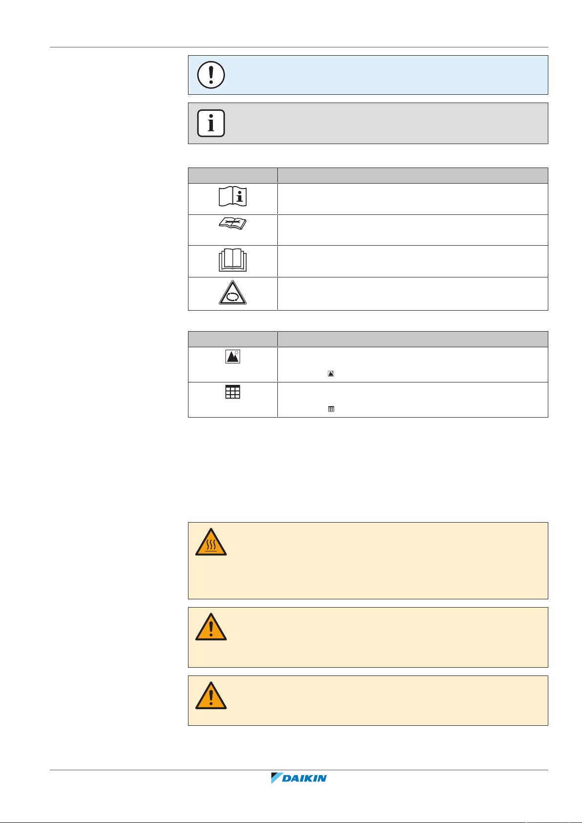
NOTICE
Indicates a situation that could result in equipment or property damage.
INFORMATION
Indicates useful tips or additional information.
Symbols used on the unit:
Symbol Explanation
Before installation, read the installation and operation
manual, and the wiring instruction sheet.
Before performing maintenance and service tasks, read the
service manual.
For more information, see the installer and user reference
guide.
The unit contains rotating parts. Be careful when servicing or
inspecting the unit.
1 | General safety precautions
Symbols used in the documentation:
1.2 For the installer
1.2.1 General
If you are NOT sure how to install or operate the unit, contact your dealer.
Symbol Explanation
Indicates a figure title or a reference to it.
Example: " 1–3 Figure title" means "Figure 3 in chapter 1".
Indicates a table title or a reference to it.
Example: " 1–3 Table title" means "Table 3 in chapter 1".
DANGER: RISK OF BURNING/SCALDING
▪ Do NOT touch the refrigerant piping, water piping or internal parts during and
immediately after operation. It could be too hot or too cold. Give it time to return
to normal temperature. If you must touch it, wear protective gloves.
▪ Do NOT touch any accidental leaking refrigerant.
ERGA04~08EAV3(A) + EHVH/X04+08S18+23EA/EJ3V+6V+9W
Daikin Altherma 3 R F
4P629086-1 – 2020.08
WARNING
Improper installation or attachment of equipment or accessories could result in
electrical shock, short-circuit, leaks, fire or other damage to the equipment. Only use
accessories, optional equipment and spare parts made or approved by Daikin.
WARNING
Make sure installation, testing and applied materials comply with applicable
legislation (on top of the instructions described in the Daikin documentation).
Installer reference guide
7
1 | General safety precautions
CAUTION
Wear adequate personal protective equipment (protective gloves, safety glasses,…)
when installing, maintaining or servicing the system.
WARNING
Tear apart and throw away plastic packaging bags so that nobody, especially
children, can play with them. Possible risk: suffocation.
WARNING
Provide adequate measures to prevent that the unit can be used as a shelter by small
animals. Small animals that make contact with electrical parts can cause
malfunctions, smoke or fire.
CAUTION
Do NOT touch the air inlet or aluminium fins of the unit.
CAUTION
▪ Do NOT place any objects or equipment on top of the unit.
▪ Do NOT sit, climb or stand on the unit.
1.2.2 Installation site
NOTICE
Works executed on the outdoor unit are best done under dry weather conditions to
avoid water ingress.
In accordance with the applicable legislation, it might be necessary to provide a
logbook with the product containing at least: information on maintenance, repair
work, results of tests, stand-by periods,…
Also, at least, following information MUST be provided at an accessible place at the
product:
▪ Instructions for shutting down the system in case of an emergency
▪ Name and address of fire department, police and hospital
▪ Name, address and day and night telephone numbers for obtaining service
In Europe, EN378 provides the necessary guidance for this logbook.
▪ Provide sufficient space around the unit for servicing and air circulation.
▪ Make sure the installation site withstands the weight and vibration of the unit.
▪ Make sure the area is well ventilated. Do NOT block any ventilation openings.
▪ Make sure the unit is level.
Installer reference guide
8
Do NOT install the unit in the following places:
▪ In potentially explosive atmospheres.
▪ In places where there is machinery that emits electromagnetic waves.
Electromagnetic waves may disturb the control system, and cause malfunction of
the equipment.
▪ In places where there is a risk of fire due to the leakage of flammable gases
(example: thinner or gasoline), carbon fibre, ignitable dust.
ERGA04~08EAV3(A) + EHVH/X04+08S18+23EA/EJ3V+6V+9W
Daikin Altherma 3 R F
4P629086-1 – 2020.08
▪ In places where corrosive gas (example: sulphurous acid gas) is produced.
Corrosion of copper pipes or soldered parts may cause the refrigerant to leak.
1.2.3 Refrigerant — in case of R410A or R32
If applicable. See the installation manual or installer reference guide of your
application for more information.
NOTICE
Make sure refrigerant piping installation complies with applicable legislation. In
Europe, EN378 is the applicable standard.
NOTICE
Make sure the field piping and connections are NOT subjected to stress.
WARNING
During tests, NEVER pressurize the product with a pressure higher than the
maximum allowable pressure (as indicated on the nameplate of the unit).
1 | General safety precautions
WARNING
Take sufficient precautions in case of refrigerant leakage. If refrigerant gas leaks,
ventilate the area immediately. Possible risks:
▪ Excessive refrigerant concentrations in a closed room can lead to oxygen
deficiency.
▪ Toxic gas might be produced if refrigerant gas comes into contact with fire.
DANGER: RISK OF EXPLOSION
Pump down – Refrigerant leakage. If you want to pump down the system, and there
is a leak in the refrigerant circuit:
▪ Do NOT use the unit's automatic pump down function, with which you can collect
all refrigerant from the system into the outdoor unit. Possible consequence: Selfcombustion and explosion of the compressor because of air going into the
operating compressor.
▪ Use a separate recovery system so that the unit's compressor does NOT have to
operate.
WARNING
ALWAYS recover the refrigerant. Do NOT release them directly into the environment.
Use a vacuum pump to evacuate the installation.
ERGA04~08EAV3(A) + EHVH/X04+08S18+23EA/EJ3V+6V+9W
Daikin Altherma 3 R F
4P629086-1 – 2020.08
NOTICE
After all the piping has been connected, make sure there is no gas leak. Use nitrogen
to perform a gas leak detection.
NOTICE
▪ To avoid compressor breakdown, do NOT charge more than the specified amount
of refrigerant.
▪ When the refrigerant system is to be opened, refrigerant MUST be treated
according to the applicable legislation.
Installer reference guide
9
1 | General safety precautions
▪ In case recharge is required, see the nameplate of the unit. It states the type of
refrigerant and necessary amount.
▪ The unit is factory charged with refrigerant and depending on pipe sizes and pipe
lengths some systems require additional charging of refrigerant.
▪ Only use tools exclusively for the refrigerant type used in the system, this to
ensure pressure resistance and prevent foreign materials from entering into the
system.
▪ Charge the liquid refrigerant as follows:
WARNING
Make sure there is no oxygen in the system. Refrigerant may only be charged after
performing the leak test and the vacuum drying.
Possible consequence: Self-combustion and explosion of the compressor because of
oxygen going into the operating compressor.
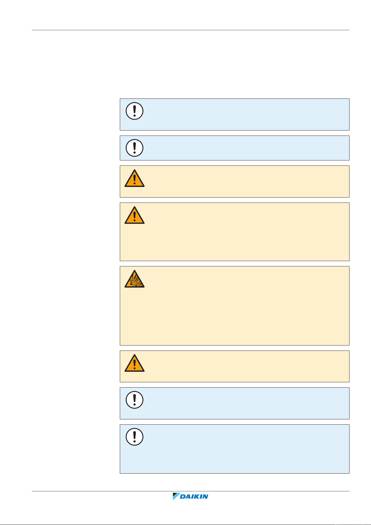
If Then
A siphon tube is present
Charge with the cylinder upright.
(i.e., the cylinder is marked with "Liquid
filling siphon attached")
A siphon tube is NOT present Charge with the cylinder upside down.
▪ Open refrigerant cylinders slowly.
▪ Charge the refrigerant in liquid form. Adding it in gas form may prevent normal
operation.
CAUTION
When the refrigerant charging procedure is done or when pausing, close the valve of
the refrigerant tank immediately. If the valve is NOT closed immediately, remaining
pressure might charge additional refrigerant. Possible consequence: Incorrect
refrigerant amount.
1.2.4 Water
Installer reference guide
10
If applicable. See the installation manual or installer reference guide of your
application for more information.
NOTICE
Make sure water quality complies with EU directive 98/83EC.
ERGA04~08EAV3(A) + EHVH/X04+08S18+23EA/EJ3V+6V+9W
Daikin Altherma 3 R F
4P629086-1 – 2020.08
1.2.5 Electrical
1 | General safety precautions
DANGER: RISK OF ELECTROCUTION
▪ Turn OFF all power supply before removing the switch box cover, connecting
electrical wiring or touching electrical parts.
▪ Disconnect the power supply for more than 10minutes, and measure the voltage
at the terminals of main circuit capacitors or electrical components before
servicing. The voltage MUST be less than 50VDC before you can touch electrical
components. For the location of the terminals, see the wiring diagram.
▪ Do NOT touch electrical components with wet hands.
▪ Do NOT leave the unit unattended when the service cover is removed.
WARNING
If NOT factory installed, a main switch or other means for disconnection, having a
contact separation in all poles providing full disconnection under overvoltage
categoryIII condition, MUST be installed in the fixed wiring.
WARNING
▪ ONLY use copper wires.
▪ Make sure the field wiring complies with the applicable legislation.
▪ All field wiring MUST be performed in accordance with the wiring diagram
supplied with the product.
▪ NEVER squeeze bundled cables and make sure they do NOT come in contact with
the piping and sharp edges. Make sure no external pressure is applied to the
terminal connections.
▪ Make sure to install earth wiring. Do NOT earth the unit to a utility pipe, surge
absorber, or telephone earth. Incomplete earth may cause electrical shock.
▪ Make sure to use a dedicated power circuit. NEVER use a power supply shared by
another appliance.
▪ Make sure to install the required fuses or circuit breakers.
▪ Make sure to install an earth leakage protector. Failure to do so may cause
electrical shock or fire.
▪ When installing the earth leakage protector, make sure it is compatible with the
inverter (resistant to high frequency electric noise) to avoid unnecessary opening
of the earth leakage protector.
ERGA04~08EAV3(A) + EHVH/X04+08S18+23EA/EJ3V+6V+9W
Daikin Altherma 3 R F
4P629086-1 – 2020.08
CAUTION
▪ When connecting the power supply: connect the earth cable first, before making
the current-carrying connections.
▪ When disconnecting the power supply: disconnect the current-carrying cables
first, before separating the earth connection.
▪ The length of the conductors between the power supply stress relief and the
terminal block itself must be as such that the current-carrying wires are tautened
before the earth wire is in case the power supply is pulled loose from the stress
relief.
Installer reference guide
11
1 | General safety precautions
Install power cables at least 1 m away from televisions or radios to prevent
interference. Depending on the radio waves, a distance of 1 m may not be
sufficient.
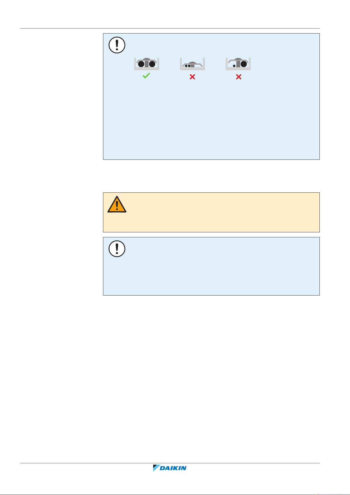
NOTICE
Precautions when laying power wiring:
▪ Do NOT connect wiring of different thicknesses to the power terminal block (slack
in the power wiring may cause abnormal heat).
▪ When connecting wiring which is the same thickness, do as shown in the figure
above.
▪ For wiring, use the designated power wire and connect firmly, then secure to
prevent outside pressure being exerted on the terminal board.
▪ Use an appropriate screwdriver for tightening the terminal screws. A screwdriver
with a small head will damage the head and make proper tightening impossible.
▪ Over-tightening the terminal screws may break them.
WARNING
▪ After finishing the electrical work, confirm that each electrical component and
terminal inside the electrical components box is connected securely.
▪ Make sure all covers are closed before starting up the unit.
NOTICE
Only applicable if the power supply is three‑phase, and the compressor has an ON/
OFF starting method.
If there exists the possibility of reversed phase after a momentary black out and the
power goes on and off while the product is operating, attach a reversed phase
protection circuit locally. Running the product in reversed phase can break the
compressor and other parts.
Installer reference guide
12
ERGA04~08EAV3(A) + EHVH/X04+08S18+23EA/EJ3V+6V+9W
Daikin Altherma 3 R F
4P629086-1 – 2020.08

2 About the documentation
In this chapter
2.1 About this document.............................................................................................................................................................. 13
2.2 Installer reference guide at a glance...................................................................................................................................... 14
2.1 About this document
Target audience
Authorised installers
Documentation set
This document is part of a documentation set. The complete set consists of:
▪ General safety precautions:
- Safety instructions that you must read before installing
- Format: Paper (in the box of the indoor unit)
2 | About the documentation
▪ Indoor unit installation manual:
- Installation instructions
- Format: Paper (in the box of the indoor unit)
▪ Outdoor unit installation manual:
- Installation instructions
- Format: Paper (in the box of the outdoor unit)
▪ Installer reference guide:
- Preparation of the installation, good practices, reference data,…
- Format: Digital files on http://www.daikineurope.com/support-and-manuals/
product-information/
▪ Addendum book for optional equipment:
- Additional info about how to install optional equipment
- Format: Paper (in the box of the indoor unit) + Digital files on http://
www.daikineurope.com/support-and-manuals/product-information/
Latest revisions of the supplied documentation may be available on the regional
Daikin website or via your dealer.
The original documentation is written in English. All other languages are
translations.
Technical engineering data
▪ A subset of the latest technical data is available on the regional Daikin website
(publicly accessible).
▪ The full set of latest technical data is available on the Daikin Business Portal
(authentication required).
ERGA04~08EAV3(A) + EHVH/X04+08S18+23EA/EJ3V+6V+9W
Daikin Altherma 3 R F
4P629086-1 – 2020.08
Installer reference guide
13
2 | About the documentation
2.2 Installer reference guide at a glance
General safety precautions Safety instructions that you must read before
About the documentation What documentation exists for the installer
About the box How to unpack the units and remove their
About the units and options ▪ How to identify the units
Application guidelines Various installation setups of the system
Preparation What to do and know before going on‑site
Installation What to do and know to install the system
Configuration What to do and know to configure the system
Commissioning What to do and know to commission the system
Chapter Description
installing
accessories
▪ Possible combinations of units and options
after it is installed
after it is configured
Hand‑over to the user What to give and explain to the user
Maintenance and service How to maintain and service the units
Troubleshooting What to do in case of problems
Disposal How to dispose of the system
Technical data Specifications of the system
Glossary Definition of terms
Field settings table Table to be filled in by the installer, and kept for
future reference
Note: There is also an installer settings table in
the user reference guide. This table has to be
filled in by the installer and handed over to the
user.
Installer reference guide
14
ERGA04~08EAV3(A) + EHVH/X04+08S18+23EA/EJ3V+6V+9W
Daikin Altherma 3 R F
4P629086-1 – 2020.08
3 | Specific installer safety instructions
3 Specific installer safety instructions
Always observe the following safety instructions and regulations.
Application guidelines (see
CAUTION
If there is more than one leaving water zone, ALWAYS install a mixing valve station in
the main zone to decrease (in heating)/increase (in cooling) the leaving water
temperature when the additional zone has demand.
Installation site (see
"7.1Preparing the installation site"[454]
WARNING
The appliance shall be stored in a room without continuously operating ignition
sources (example: open flames, an operating gas appliance or an operating electric
heater).
WARNING
DO NOT reuse refrigerant piping that has been used with any other refrigerant.
Replace the refrigerant pipes or clean thoroughly.
WARNING
▪ Do NOT pierce or burn.
▪ Do NOT use means to accelerate the defrosting process or to clean the
equipment, other than those recommended by the manufacturer.
▪ Be aware that R32 refrigerant does NOT contain an odour.
"6Application guidelines"[429]
)
)
WARNING
The appliance shall be stored so as to prevent mechanical damage and in a wellventilated room without continuously operating ignition sources (example: open
flames, an operating gas appliance or an operating electric heater) and have a room
size as specified below.
Charging refrigerant (see
WARNING
If the total refrigerant charge in the system is ≥1.84 kg (i.e. if the piping length is
≥27 m), you need to comply with the minimum floor area requirements for the
indoor unit. For more information, see "7.1.3Installation site requirements of the
indoor unit"[458].
CAUTION
To avoid compressor breakdown, do NOT charge more than the specified amount of
refrigerant.
WARNING
▪ Only use R32 as refrigerant. Other substances may cause explosions and
accidents.
▪ R32 contains fluorinated greenhouse gases. Its global warming potential (GWP)
value is 675. Do NOT vent these gases into the atmosphere.
▪ When charging refrigerant, ALWAYS use protective gloves and safety glasses.
"8.5Charging refrigerant"[490]
)
ERGA04~08EAV3(A) + EHVH/X04+08S18+23EA/EJ3V+6V+9W
Daikin Altherma 3 R F
4P629086-1 – 2020.08
Installer reference guide
15
3 | Specific installer safety instructions
a
Electrical installation (see
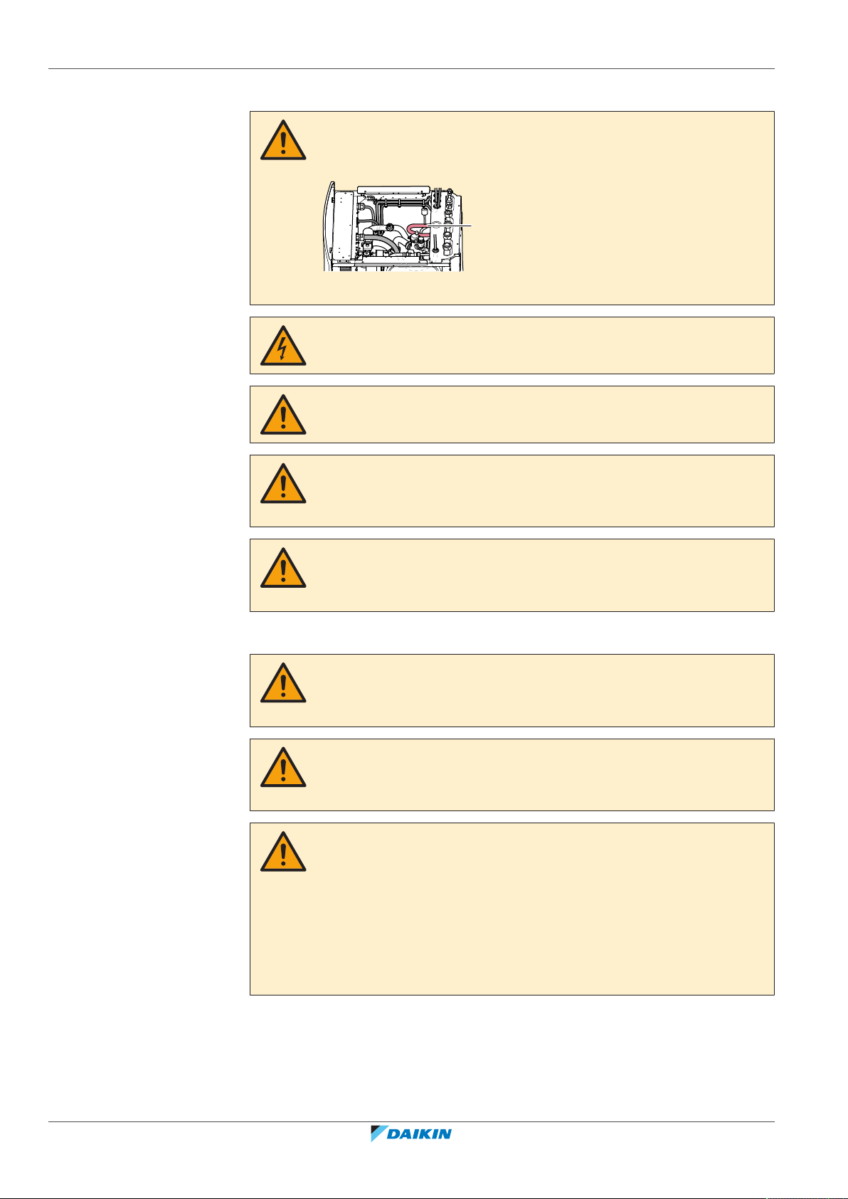
WARNING
Make sure that the electrical wiring does NOT touch the refrigerant gas pipe, which
can be very hot.
a Refrigerant gas pipe
DANGER: RISK OF ELECTROCUTION
WARNING
ALWAYS use multicore cable for power supply cables.
CAUTION
To guarantee the unit is completely earthed, always connect the backup heater
power supply and the earth cable.
"9Electrical installation"[497]
)
WARNING
The backup heater MUST have a dedicated power supply and MUST be protected by
the safety devices required by the applicable legislation.
Configuration (see
CAUTION
The disinfection function settings MUST be configured by the installer according to
the applicable legislation.
CAUTION
Be sure that the disinfection function start time [5.7.3] with defined duration [5.7.5]
is NOT interrupted by possible domestic hot water demand.
WARNING
Be aware that the domestic hot water temperature at the hot water tap will be equal
to the value selected in field setting [2-03] after a disinfection operation.
When the high domestic hot water temperature can be a potential risk for human
injuries, a mixing valve (field supply) shall be installed at the hot water outlet
connection of the domestic hot water tank. This mixing valve shall secure that the
hot water temperature at the hot water tap never rise above a set maximum value.
This maximum allowable hot water temperature shall be selected according to the
applicable legislation.
"10Configuration"[4126]
)
Installer reference guide
16
ERGA04~08EAV3(A) + EHVH/X04+08S18+23EA/EJ3V+6V+9W
Daikin Altherma 3 R F
4P629086-1 – 2020.08
3 | Specific installer safety instructions
CAUTION
Make sure to observe all rules mentioned in application guideline 5 when bivalent
operation function is enabled.
Daikin shall NOT be held liable for any damage resulting from failure to observe this
rule.
Maintenance and service (see
CAUTION
Water coming out of the valve may be very hot.
WARNING
If the internal wiring is damaged, it has to be replaced by the manufacturer, its
service agent or similarly qualified persons.
CAUTION
Although the water circuit is drained, some water may be spilled when removing the
magnetic filter/dirt separator from the filter housing. ALWAYS clean up spilled water.
CAUTION
To protect the piping connected to the magnetic filter/dirt separator from damage it
is recommended to perform this procedure with the magnetic filter/dirt separator
removed from the unit.
CAUTION
Opening the magnetic filter/dirt separator is ONLY required in case of severe issues.
Preferably this action is never to be done during the complete lifetime of the
magnetic filter/dirt separator.
"13Maintenance and service"[4218]
)
CAUTION
Check the condition of the O-rings and replace if needed. Apply water to the O-rings
before installation.
CAUTION
Make sure to open the valve (if equipped) towards the expansion vessel, otherwise
the overpressure will be generated.
Troubleshooting (see
WARNING
Prevent hazards due to inadvertent resetting of the thermal cut-out: power to this
appliance MUST NOT be supplied through an external switching device, such as a
timer, or connected to a circuit that is regularly turned ON and OFF by the utility.
"14Troubleshooting"[4225]
)
ERGA04~08EAV3(A) + EHVH/X04+08S18+23EA/EJ3V+6V+9W
Daikin Altherma 3 R F
4P629086-1 – 2020.08
Installer reference guide
17
3 | Specific installer safety instructions
WARNING
▪ When carrying out an inspection on the switch box of the unit, ALWAYS make
sure that the unit is disconnected from the mains. Turn off the respective circuit
breaker.
▪ When a safety device was activated, stop the unit and find out why the safety
device was activated before resetting it. NEVER shunt safety devices or change
their values to a value other than the factory default setting. If you are unable to
find the cause of the problem, call your dealer.
WARNING
Air purging heat emitters or collectors. Before you purge air from heat emitters or
collectors, check if or is displayed on the home screen of the user interface.
▪ If not, you can purge air immediately.
▪ If yes, make sure that the room where you want to purge air is sufficiently
ventilated. Reason: Refrigerant might leak into the water circuit, and
subsequently into the room when you purge air from the heat emitters or
collectors.
Disposal (see
"15Disposal"[4236]
)
DANGER: RISK OF EXPLOSION
Pump down – Refrigerant leakage. If you want to pump down the system, and there
is a leak in the refrigerant circuit:
▪ Do NOT use the unit's automatic pump down function, with which you can collect
all refrigerant from the system into the outdoor unit. Possible consequence: Selfcombustion and explosion of the compressor because of air going into the
operating compressor.
▪ Use a separate recovery system so that the unit's compressor does NOT have to
operate.
3.1 Instructions for equipment using R32 refrigerant
WARNING: FLAMMABLE MATERIAL
The refrigerant inside this unit is mildly flammable.
WARNING
▪ Do NOT pierce or burn.
▪ Do NOT use means to accelerate the defrosting process or to clean the
equipment, other than those recommended by the manufacturer.
▪ Be aware that R32 refrigerant does NOT contain an odour.
Installer reference guide
18
WARNING
The appliance shall be stored so as to prevent mechanical damage and in a wellventilated room without continuously operating ignition sources (example: open
flames, an operating gas appliance or an operating electric heater) and have a room
size as specified below.
ERGA04~08EAV3(A) + EHVH/X04+08S18+23EA/EJ3V+6V+9W
Daikin Altherma 3 R F
4P629086-1 – 2020.08
3 | Specific installer safety instructions
WARNING
Make sure installation, servicing, maintenance and repair comply with instructions
from Daikin and with applicable legislation (for example national gas regulation) and
are executed only by authorised persons.
WARNING
If one or more rooms are connected to the unit using a duct system, make sure:
▪ there are no operating ignition sources (example: open flames, an operating gas
appliance or an operating electric heater) in case the floor area is less than the
minimum floor area A (m²).
▪ no auxiliary devices, which may be a potential ignition source, are installed in the
duct work (example: hot surfaces with a temperature exceeding 700°C and
electric switching device);
▪ only auxiliary devices approved by the manufacturer are used in the duct work;
▪ air inlet AND outlet are connected directly to the same room by ducting. Do NOT
use spaces such as a false ceiling as a duct for the air inlet or outlet.
NOTICE
▪ Precautions shall be taken to avoid excessive vibration or pulsation to
refrigeration piping.
▪ Protection devices, piping and fittings shall be protected as far as possible against
adverse environmental effects.
▪ Provision shall be made for expansion and contraction of long runs of piping.
▪ Piping in refrigerating systems shall be designed and installed such as to minimise
the likelihood of hydraulic shock damaging the system.
▪ The indoor equipment and pipes shall be securely mounted and guarded such
that accidental rupture of equipment or pipes cannot occur from events such as
moving furniture or reconstruction activities.
CAUTION
Do NOT use potential sources of ignition in searching for or detection of refrigerant
leaks.
NOTICE
▪ Do NOT re-use joints and copper gaskets which have been used already.
▪ Joints made in installation between parts of refrigerant system shall be accessible
for maintenance purposes.
ERGA04~08EAV3(A) + EHVH/X04+08S18+23EA/EJ3V+6V+9W
Daikin Altherma 3 R F
4P629086-1 – 2020.08
Installer reference guide
19
4 | About the box
1 2
4 About the box
In this chapter
4.1 Overview: About the box
4.1 Overview: About the box........................................................................................................................................................ 20
4.2 Outdoor unit ........................................................................................................................................................................... 20
4.2.1 To unpack the outdoor unit ................................................................................................................................... 20
4.2.2 To handle the outdoor unit.................................................................................................................................... 21
4.2.3 To remove the accessories from the outdoor unit ............................................................................................... 21
4.3 Indoor unit .............................................................................................................................................................................. 22
4.3.1 To unpack the indoor unit...................................................................................................................................... 22
4.3.2 To remove the accessories from the indoor unit .................................................................................................. 22
4.3.3 To handle the indoor unit ...................................................................................................................................... 22
This chapter describes what you have to do after the boxes with the outdoor and
indoor unit are delivered on-site.
Keep the following in mind:
▪ At delivery, the unit MUST be checked for damage. Any damage MUST be
reported immediately to the claims agent of the carrier.
4.2 Outdoor unit
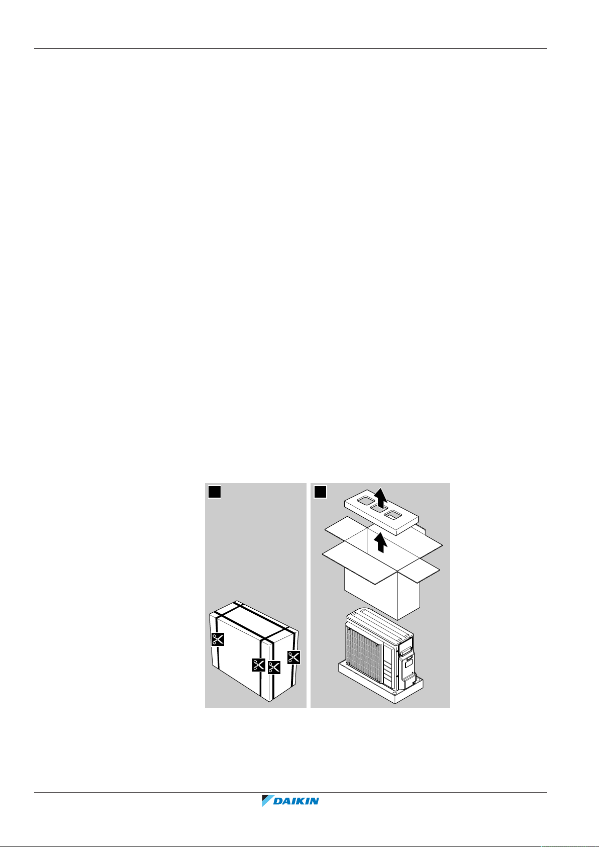
4.2.1 To unpack the outdoor unit
▪ Bring the packed unit as close as possible to its final installation position to
prevent damage during transport.
▪ Prepare the path along which you want to bring the unit inside in advance.
Installer reference guide
20
ERGA04~08EAV3(A) + EHVH/X04+08S18+23EA/EJ3V+6V+9W
Daikin Altherma 3 R F
4P629086-1 – 2020.08
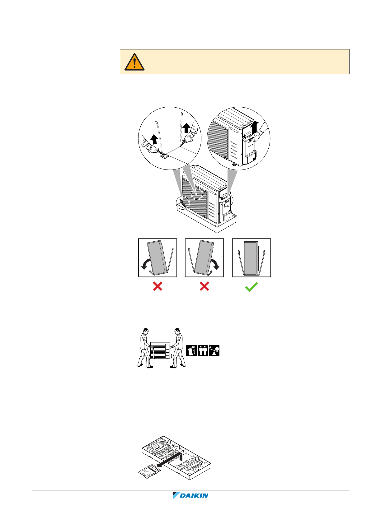
4.2.2 To handle the outdoor unit
2
1
1
CAUTION
To avoid injury, do NOT touch the air inlet or aluminium fins of the unit.
1 Handle the unit using the sling to the left and the handle to the right. Pull up
both sides of the sling at the same time to prevent disconnection of the sling
from the unit.
4 | About the box
2 While handling the unit:
▪ Keep both sides of the sling level.
▪ Keep your back straight.
3 After mounting the unit, remove the sling from the unit by pulling 1 side of the
sling.
4.2.3 To remove the accessories from the outdoor unit
1 Lift the outdoor unit. See "4.2.2To handle the outdoor unit"[421].
2 Remove the accessories at the bottom of the package.
ERGA04~08EAV3(A) + EHVH/X04+08S18+23EA/EJ3V+6V+9W
Daikin Altherma 3 R F
4P629086-1 – 2020.08
Installer reference guide
21
4 | About the box
ENERG
IJAY
IAIE
ENERG
IJAY
IAIE
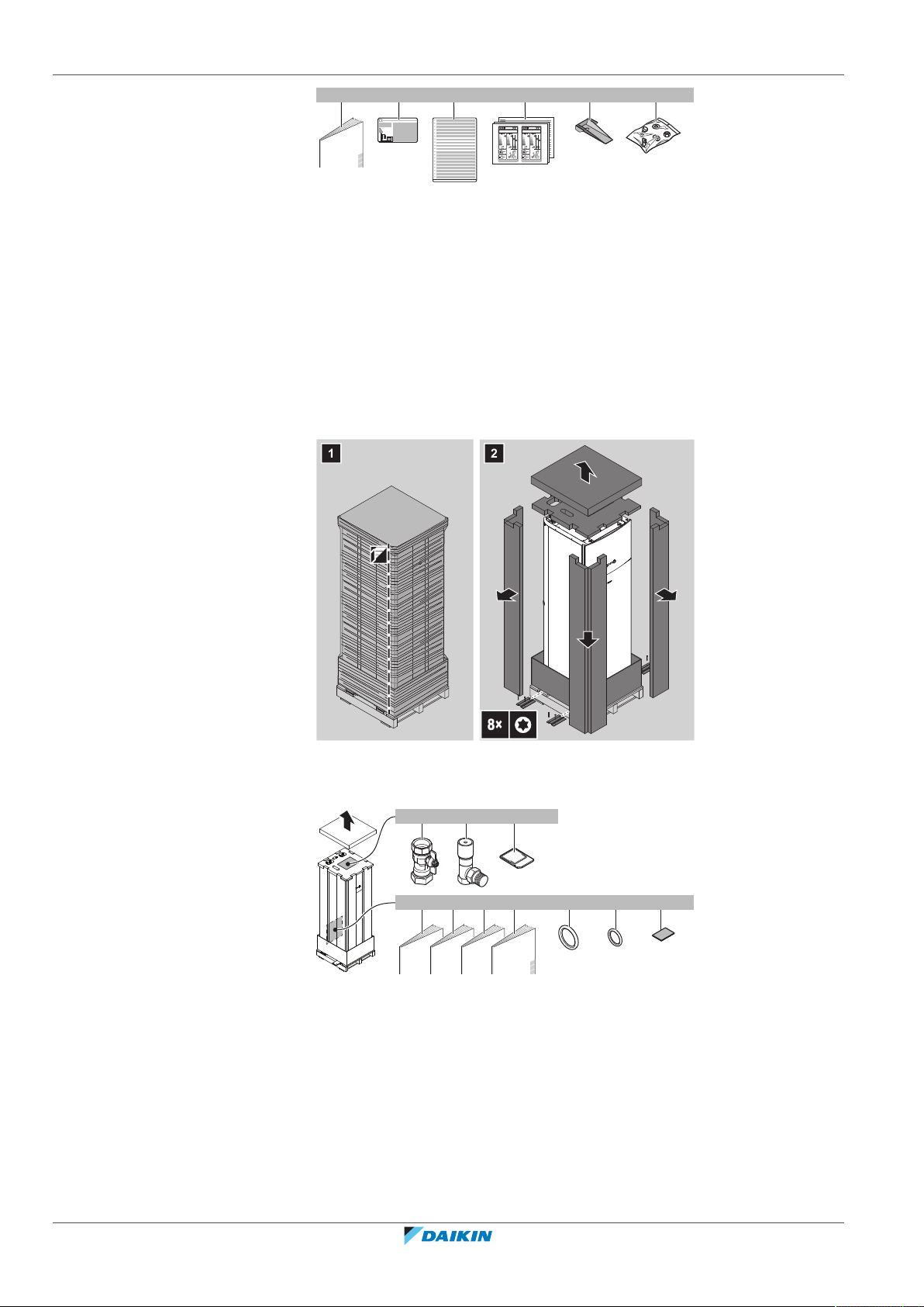
1×1× 1× 1× 2× 1×
da b c e f
1 2
8×
1×2×
4×
1×
4× 1×
1× 1× 1× 1×
a b c
h i jd e f g
4.3 Indoor unit
4.3.1 To unpack the indoor unit
a Outdoor unit installation manual
b Fluorinated greenhouse gases label
c Multilingual fluorinated greenhouse gases label
d Energy label
e Unit mounting plate
f Bolts, nuts, washers, spring washers and wire clamp
4.3.2 To remove the accessories from the indoor unit
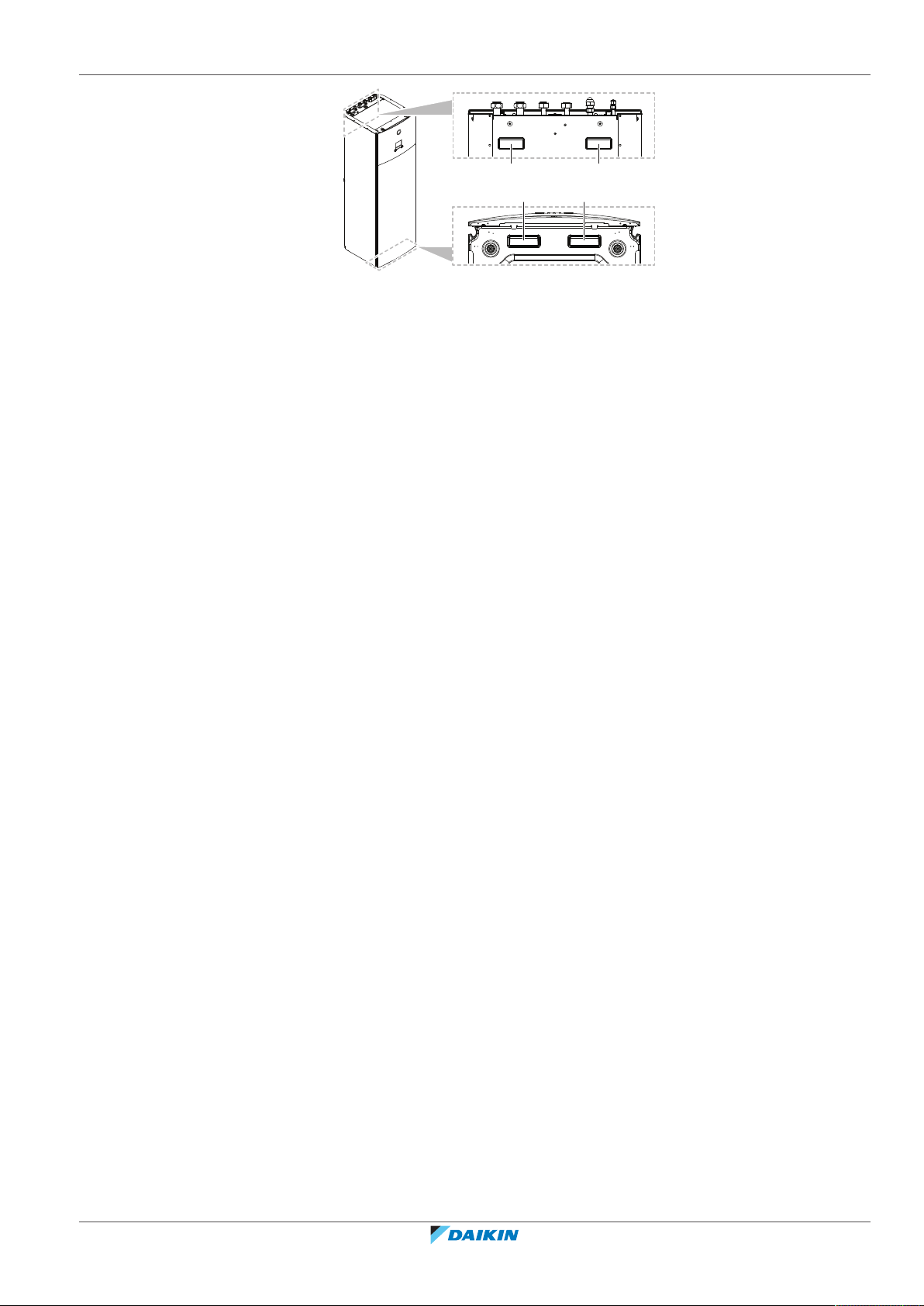
4.3.3 To handle the indoor unit
Installer reference guide
22
Use the handles at the back and at the bottom to carry the unit.
a Shut-off valves for water circuit
b Overpressure bypass valve
c WLAN cartridge
d General safety precautions
e Addendum book for optional equipment
f Indoor unit installation manual
g Operation manual
h Sealing rings for shut-off valves (space heating water circuit)
i Sealing rings for field-supplied shut-off valves (domestic hot water circuit)
j Sealing tape for low voltage wiring intake
ERGA04~08EAV3(A) + EHVH/X04+08S18+23EA/EJ3V+6V+9W
Daikin Altherma 3 R F
4P629086-1 – 2020.08
4 | About the box
b
a a
b
a Handles at the back of the unit
b Handles at the bottom of the unit. Carefully tilt the unit to the back so that the handles become visible.
ERGA04~08EAV3(A) + EHVH/X04+08S18+23EA/EJ3V+6V+9W
Daikin Altherma 3 R F
4P629086-1 – 2020.08
Installer reference guide
23
5 | About the units and options
5 About the units and options
In this chapter
5.1 Overview: About the units and options ................................................................................................................................. 24
5.2 Identification........................................................................................................................................................................... 24
5.2.1 Identification label: Outdoor unit .......................................................................................................................... 24
5.2.2 Identification label: Indoor unit ............................................................................................................................. 25
5.3 Combining units and options.................................................................................................................................................. 25
5.3.1 Possible options for the outdoor unit.................................................................................................................... 25
5.3.2 Possible options for the indoor unit ...................................................................................................................... 26
5.3.3 Possible combinations of indoor unit and outdoor unit ....................................................................................... 28
5.1 Overview: About the units and options
This chapter contains information about:
▪ Identifying the outdoor unit
▪ Identifying the indoor unit
▪ Combining the outdoor unit with options
▪ Combining the indoor unit with options
5.2 Identification
NOTICE
When installing or servicing several units at the same time, make sure NOT to switch
the service panels between different models.
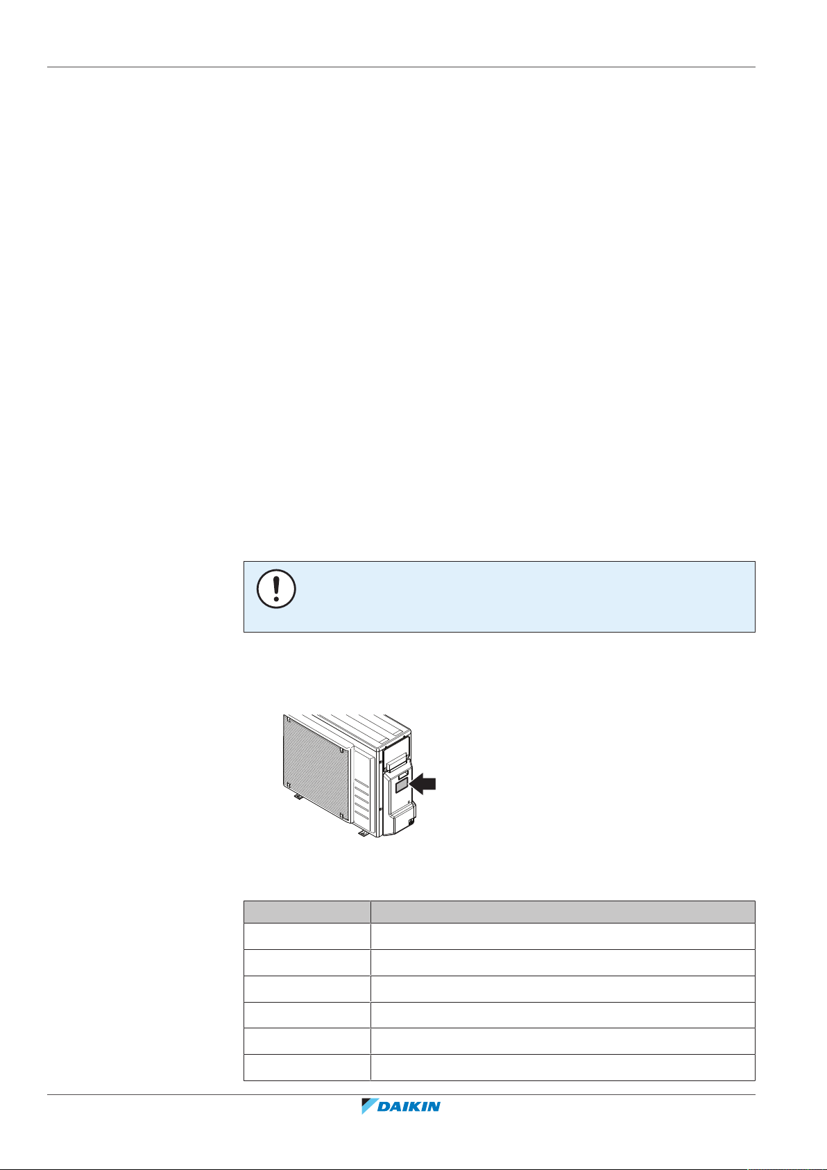
5.2.1 Identification label: Outdoor unit
Location
Model identification
Installer reference guide
24
Example: ERGA06DAV3 A
Code Explanation
ER European split outdoor pair heat pump
G Medium water temperature – ambient zone: −10~−20°C
A Refrigerant R32
06 Capacity class
DA Model series
V3 Power supply
ERGA04~08EAV3(A) + EHVH/X04+08S18+23EA/EJ3V+6V+9W
Daikin Altherma 3 R F
4P629086-1 – 2020.08
Code Explanation
A A=Austrian model
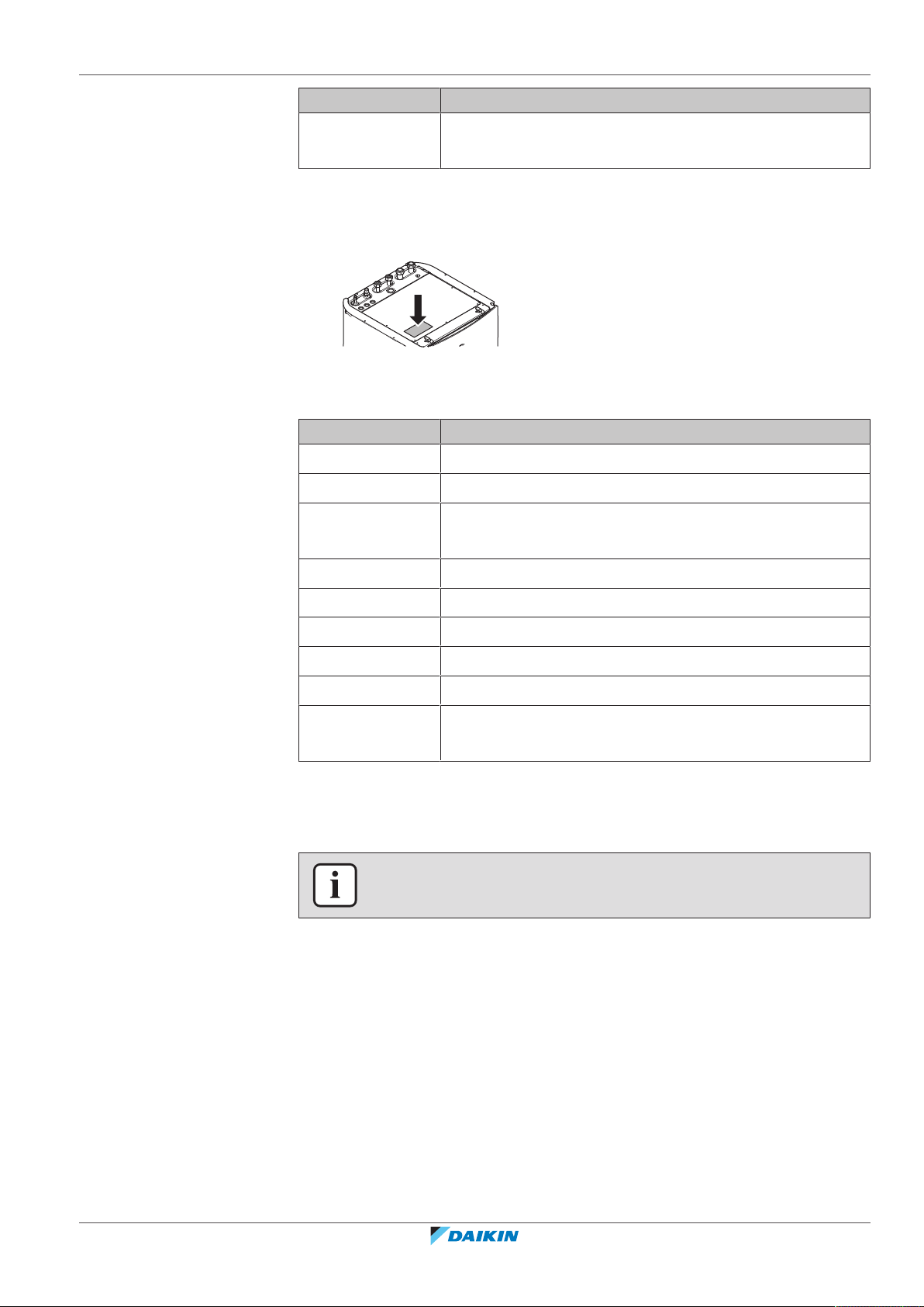
5.2.2 Identification label: Indoor unit
Location
Model identification
Example: EHVX04S18EA6VG
Code Description
E European model
HV Floor-standing indoor unit with integrated tank
5 | About the units and options
[—]=Non-Austrian model
X H=Heating only
X=Heating/cooling
04 Capacity class
S Integrated tank material: Stainless steel
18 Integrated tank volume
EA Model series
6V Backup heater model
G G=Grey model
[—]=White model
5.3 Combining units and options
INFORMATION
Certain options might not be available in your country.
5.3.1 Possible options for the outdoor unit
Drain pan kit (EKDP008D)
The drain pan kit is required to gather the drain from the outdoor unit. The drain
pan kit consists of:
▪ Drain pan
▪ Installation brackets
For installation instructions, see the installation manual of the drain pan.
Drain pan heater (EKDPH008CA)
The drain pan heater is required to avoid freezing-up of the drain pan.
ERGA04~08EAV3(A) + EHVH/X04+08S18+23EA/EJ3V+6V+9W
Daikin Altherma 3 R F
4P629086-1 – 2020.08
Installer reference guide
25

5 | About the units and options
It is recommended to install this option in colder regions with possible low ambient
temperatures or heavy snowfall.
For installation instructions, see the installation manual of the drain pan heater.
U-beams (EKFT008D)
The U-beams are installation brackets on which the outdoor unit can be installed.
It is recommended to install this option in colder regions with possible low ambient
temperatures or heavy snowfall.
For installation instructions, see the installation manual of the outdoor unit.
Low sound cover (EKLN08A1)
In sound sensitive areas (e.g. near a bedroom), you can install the low sound cover
to decrease the operation noise of the outdoor unit.
You can install the low sound cover:
▪ On mounting feet to the ground. This must withstand 200kg.
▪ On brackets to the wall. This must withstand 200kg.
If you install the low sound cover, you also need to install one of the following
options:
▪ Recommended: Drain pan kit (with or without drain pan heater)
▪ U-beams
For installation instructions, see the installation manual of the low sound cover.
5.3.2 Possible options for the indoor unit
User interface used as room thermostat (BRC1HHDA)
▪ The user interface used as room thermostat can only be used in combination
with the user interface connected to the indoor unit.
▪ The user interface used as room thermostat needs to be installed in the room
that you want to control.
For installation instructions, see the installation and operation manual of the user
interface used as room thermostat.
Room thermostat (EKRTWA, EKRTR1)
You can connect an optional room thermostat to the indoor unit. This thermostat
can either be wired (EKRTWA) or wireless (EKRTR1).
For installation instructions, see the installation manual of the room thermostat
and addendum book for optional equipment.
Remote sensor for wireless thermostat (EKRTETS)
Installer reference guide
26
You can use the remote indoor temperature sensor (EKRTETS) only in combination
with the wireless thermostat (EKRTR1).
For installation instructions, see the installation manual of the room thermostat
and the addendum book for optional equipment.
Digital I/O PCB (EKRP1HBAA)
The digital I/O PCB is required to provide following signals:
▪ Alarm output
▪ Space heating/cooling On/OFF output
▪ Changeover to external heat source
ERGA04~08EAV3(A) + EHVH/X04+08S18+23EA/EJ3V+6V+9W
Daikin Altherma 3 R F
4P629086-1 – 2020.08
5 | About the units and options
For installation instructions, see the installation manual of the digital I/O PCB and
addendum book for optional equipment.
Demand PCB (EKRP1AHTA)
To enable the power saving consumption control by digital inputs you must install
the demand PCB.
For installation instructions, see the installation manual of the demand PCB and
addendum book for optional equipment.
Remote indoor sensor (KRCS01-1)
By default the internal user interface sensor will be used as room temperature
sensor.
As an option the remote indoor sensor can be installed to measure the room
temperature on another location.
For installation instructions, see the installation manual of the remote indoor
sensor and addendum book for optional equipment.
INFORMATION
▪ The remote indoor sensor can only be used in case the user interface is
configured with room thermostat functionality.
▪ You can only connect either the remote indoor sensor or the remote outdoor
sensor.
Remote outdoor sensor (EKRSCA1)
By default the sensor inside the outdoor unit will be used to measure the outdoor
temperature.
As an option the remote outdoor sensor can be installed to measure the outdoor
temperature on another location (e.g. to avoid direct sunlight) to have an
improved system behaviour.
For installation instructions, see the installation manual of the remote outdoor
sensor and the addendum book for optional equipment.
INFORMATION
You can only connect either the remote indoor sensor or the remote outdoor sensor.
PC cable (EKPCCAB4)
The PC cable makes a connection between the switch box of the indoor unit and a
PC. It gives the possibility to update the software of the indoor unit.
For installation instructions, see the installation manual of the PC cable.
Pipe bend kit (EKHVTC)
When the indoor unit is installed in a place with limited space, a pipe bend kit can
be installed to facilitate the connection to the refrigerant liquid and gas
connections of the indoor unit.
For installation instructions, see the instruction sheet of the pipe bend kit.
Heat pump convector (FWXV)
For providing space heating/cooling, it is possible to use heat pump convectors
(FWXV).
For installation instructions, see the installation manual of the heat pump
convectors, and the addendum book for optional equipment.
ERGA04~08EAV3(A) + EHVH/X04+08S18+23EA/EJ3V+6V+9W
Daikin Altherma 3 R F
4P629086-1 – 2020.08
Installer reference guide
27
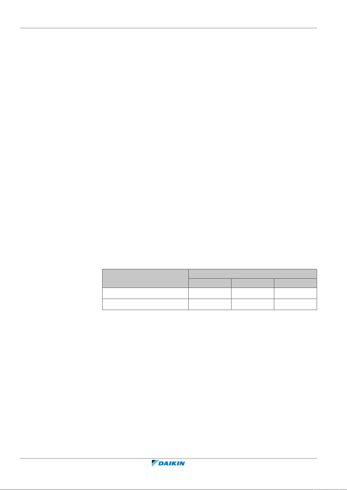
5 | About the units and options
LAN adapter for smartphone control + Smart Grid applications (BRP069A61)
You can install this LAN adapter to:
▪ Control the system via a smartphone app.
▪ Use the system in various Smart Grid applications.
For installation instructions, see the installation manual of the LAN adapter.
LAN adapter for smartphone control (BRP069A62)
You can install this LAN adapter to control the system via a smartphone app.
For installation instructions, see the installation manual of the LAN adapter.
Conversion kit (EKHVCONV4)
Use the connection kit to convert a heating only model to a reversible model.
For installation instructions, see the installation manual of the conversion kit.
WLAN adapter module (BRP069A71)
A WLAN cartridge (to be plugged into the MMI) is delivered as indoor unit
accessory. Alternatively (e.g. in case of weak signal strength), you can install the
optional wireless LAN adapter module BRP069A71.
For installation instructions, see the installation manual of the WLAN adapter
module and the addendum book for optional equipment.
Smart grid relay kit (EKRELSG)
The installation of the optional Smart grid relay kit is required in case of high
voltage Smart grid contacts (EKRELSG).
For installation instructions, see "9.3.11To connect a Smart Grid"[4120].
5.3.3 Possible combinations of indoor unit and outdoor unit
Indoor unit Outdoor unit
ERGA04 ERGA06 ERGA08
EHVH/X04 O — —
EHVH/X08 — O O
Installer reference guide
28
ERGA04~08EAV3(A) + EHVH/X04+08S18+23EA/EJ3V+6V+9W
Daikin Altherma 3 R F
4P629086-1 – 2020.08
6 Application guidelines
In this chapter
6.1 Overview: Application guidelines........................................................................................................................................... 29
6.2 Setting up the space heating/cooling system ........................................................................................................................ 29
6.2.1 Single room............................................................................................................................................................. 30
6.2.2 Multiple rooms – OneLWT zone ........................................................................................................................... 34
6.2.3 Multiple rooms – TwoLWT zones ......................................................................................................................... 38
6.3 Setting up an auxiliary heat source for space heating........................................................................................................... 40
6.4 Setting up the domestic hot water tank ................................................................................................................................ 43
6.4.1 System layout – Integrated DHW tank .................................................................................................................. 43
6.4.2 Selecting the volume and desired temperature for the DHW tank ...................................................................... 43
6.4.3 Setup and configuration – DHW tank .................................................................................................................... 45
6.4.4 DHW pump for instant hot water .......................................................................................................................... 45
6.4.5 DHW pump for disinfection ................................................................................................................................... 45
6.5 Setting up the energy metering ............................................................................................................................................. 46
6.5.1 Produced heat ........................................................................................................................................................ 46
6.5.2 Consumed energy .................................................................................................................................................. 47
6.5.3 Normal kWh rate power supply............................................................................................................................. 47
6.5.4 Preferential kWh rate power supply...................................................................................................................... 49
6.6 Setting up the power consumption control........................................................................................................................... 49
6.6.1 Permanent power limitation.................................................................................................................................. 50
6.6.2 Power limitation activated by digital inputs .......................................................................................................... 50
6.6.3 Power limitation process ....................................................................................................................................... 52
6.7 Setting up an external temperature sensor........................................................................................................................... 52
6 | Application guidelines
6.1 Overview: Application guidelines
The purpose of the application guidelines is to give a glance of the possibilities of
the heatpump system.
NOTICE
▪ The illustrations in the application guidelines are meant for reference only, and
are NOT to be used as detailed hydraulic diagrams. The detailed hydraulic
dimensioning and balancing are NOT shown, and are the responsibility of the
installer.
▪ For more information about the configuration settings to optimize heat pump
operation, see "10Configuration"[4126].
This chapter contains application guidelines for:
▪ Setting up the space heating/cooling system
▪ Setting up an auxiliary heat source for space heating
▪ Setting up the domestic hot water tank
▪ Setting up the energy metering
▪ Setting up the power consumption control
▪ Setting up an external temperature sensor
6.2 Setting up the space heating/cooling system
The heat pump system supplies leaving water to heat emitters in one or more
rooms.
ERGA04~08EAV3(A) + EHVH/X04+08S18+23EA/EJ3V+6V+9W
Daikin Altherma 3 R F
4P629086-1 – 2020.08
Installer reference guide
29
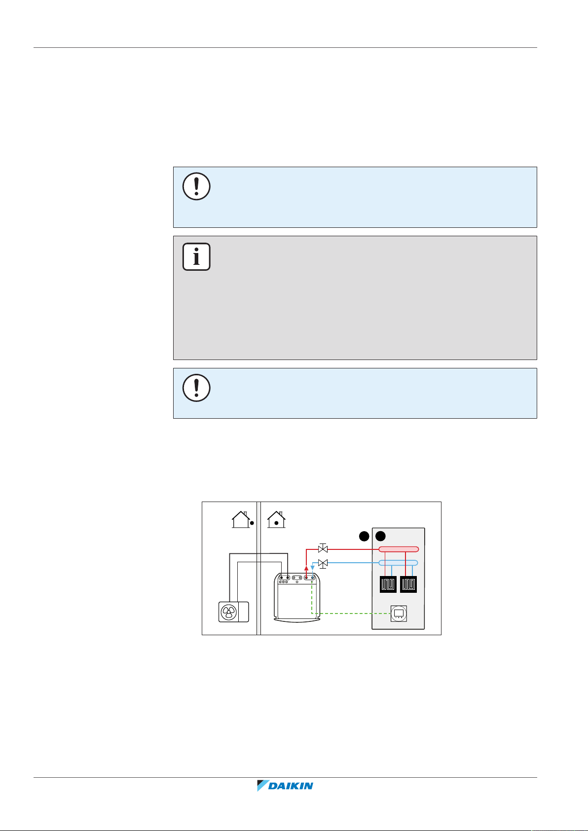
6 | Application guidelines
A
B
a
Because the system offers a wide flexibility to control the temperature in each
room, you need to answer the following questions first:
▪ How many rooms are heated or cooled by the heatpump system?
▪ Which heat emitter types are used in each room and what is their design leaving
water temperature?
Once the space heating/cooling requirements are clear, we recommend to follow
the setup guidelines below.
NOTICE
If an external room thermostat is used, the external room thermostat will control the
room frost protection. However, the room frost protection is only possible if [C.2]
Space heating/cooling=On.
INFORMATION
In case an external room thermostat is used and room frost protection needs to be
guaranteed in all conditions, then you have to set Emergency [9.5.1] to one of the
following:
▪ Automatic
▪ auto SH reduced/DHW on
▪ auto SH reduced/DHW off
▪ auto SH normal/DHW off
6.2.1 Single room
Underfloor heating or radiators – Wired room thermostat
NOTICE
An overpressure bypass valve can be integrated in the system. Keep in mind that this
valve might not be shown on the illustrations.
Setup
A Main leaving water temperature zone
B One single room
a Dedicated Human Comfort Interface (BRC1HHDA used as room thermostat)
▪ The underfloor heating or radiators are directly connected to the indoor unit.
Installer reference guide
30
▪ The room temperature is controlled by the dedicated Human Comfort Interface
(BRC1HHDA used as room thermostat).
ERGA04~08EAV3(A) + EHVH/X04+08S18+23EA/EJ3V+6V+9W
Daikin Altherma 3 R F
4P629086-1 – 2020.08
 Loading...