

Daikin ERLQ004-006-008CA, EHVH04SU18CB6W, EHVH08SU18CB6W, EHVH08SU26CB6W Installer reference guide
+
Installer reference guide
Daikin Altherma – Low temperature split
ERLQ004-006-008CA
EHVH04SU18CB6W
EHVH08SU18CB6W
EHVH08SU26CB6W
Installer reference guide
Daikin Altherma – Low temperature split
English

Table of contents
Table of contents
1 General safety precautions 3
1.1 About the documentation .......................................................... 3
1.1.1 Meaning of warnings and symbols.............................. 3
1.2 For the installer.......................................................................... 4
1.2.1 General ....................................................................... 4
1.2.2 Installation site ............................................................ 4
1.2.3 Refrigerant .................................................................. 4
1.2.4 Brine............................................................................ 5
1.2.5 Water .......................................................................... 5
1.2.6 Electrical ..................................................................... 6
2 About the documentation 6
2.1 About this document.................................................................. 6
2.2 Installer reference guide at a glance ......................................... 7
3 About the box 7
3.1 Overview: About the box ........................................................... 7
3.2 Outdoor unit............................................................................... 7
3.2.1 To unpack the outdoor unit ......................................... 7
3.2.2 To remove the accessories from the outdoor unit....... 8
3.3 Indoor unit ................................................................................. 8
3.3.1 To unpack the indoor unit ........................................... 8
3.3.2 To remove the accessories from the indoor unit......... 8
3.4 Domestic hot water tank kit ....................................................... 9
3.4.1 To unpack the domestic hot water tank kit.................. 9
3.4.2 To remove the accessories from the domestic hot
water tank kit............................................................... 9
4 About the units and options 9
4.1 Overview: About the units and options...................................... 9
4.2 Identification .............................................................................. 10
4.2.1 Identification label: Outdoor unit ................................. 10
4.2.2 Identification label: Indoor unit .................................... 10
4.3 Combining units and options ..................................................... 10
4.3.1 Possible options for the outdoor unit........................... 10
4.3.2 Possible options for the indoor unit............................. 10
4.3.3 Possible combinations of indoor unit and outdoor
unit .............................................................................. 12
5 Application guidelines 12
5.1 Overview: Application guidelines............................................... 12
5.2 Setting up the space heating system ........................................ 12
5.2.1 Single room................................................................. 12
5.2.2 Multiple rooms – OneLWT zone ................................ 14
5.2.3 Multiple rooms – TwoLWT zones............................... 16
5.3 Setting up an auxiliary heat source for space heating............... 17
5.4 Setting up the domestic hot water tank ..................................... 18
5.4.1 System layout – Integrated DHW tank........................ 18
5.4.2 Selecting the volume and desired temperature for
the DHW tank.............................................................. 18
5.4.3 Setup and configuration – DHW tank.......................... 19
5.4.4 DHW pump for instant hot water................................. 19
5.4.5 DHW pump for disinfection ......................................... 19
5.5 Setting up the energy metering ................................................. 19
5.5.1 Produced heat............................................................. 19
5.5.2 Consumed energy....................................................... 20
5.5.3 Normal kWh rate power supply................................... 20
5.5.4 Preferential kWh rate power supply............................ 20
5.6 Setting up the power consumption control ................................ 21
5.6.1 Permanent power limitation ........................................ 21
5.6.2 Power limitation activated by digital inputs ................. 21
5.6.3 Power limitation process ............................................. 22
5.7 Setting up an external temperature sensor ............................... 22
6 Preparation 23
6.1 Overview: Preparation............................................................... 23
6.2 Preparing installation site .......................................................... 23
6.2.1 Installation site requirements of the outdoor unit ......... 23
6.2.2 Additional installation site requirements of the
outdoor unit in cold climates ........................................ 24
6.2.3 Installation site requirements of the indoor unit ........... 24
6.2.4 Installation site requirements of the domestic hot
water tank kit................................................................ 24
6.3 Preparing refrigerant piping........................................................ 24
6.3.1 Refrigerant piping requirements................................... 24
6.3.2 Refrigerant piping insulation ........................................ 25
6.4 Preparing water piping ............................................................... 25
6.4.1 Water circuit requirements ........................................... 25
6.4.2 Formula to calculate the expansion vessel pre-
pressure ....................................................................... 26
6.4.3 To check the water volume and flow rate .................... 26
6.4.4 Changing the pre-pressure of the expansion vessel.... 27
6.4.5 To check the water volume: Examples ........................ 28
6.5 Preparing electrical wiring .......................................................... 28
6.5.1 About preparing electrical wiring.................................. 28
6.5.2 About preferential kWh rate power supply ................... 28
6.5.3 Overview of electrical connections except external
actuators ...................................................................... 28
6.5.4 Overview of electrical connections for external and
internal actuators ......................................................... 29
7 Installation 29
7.1 Overview: Installation ................................................................. 29
7.2 Opening the units ....................................................................... 29
7.2.1 About opening the units ............................................... 29
7.2.2 To open the outdoor unit.............................................. 30
7.2.3 To open the indoor unit ................................................ 30
7.2.4 To open the switch box cover of the indoor unit .......... 30
7.3 Mounting the outdoor unit........................................................... 30
7.3.1 About mounting the outdoor unit.................................. 30
7.3.2 Precautions when mounting the outdoor unit............... 31
7.3.3 To provide the installation structure ............................. 31
7.3.4 To install the outdoor unit............................................. 32
7.3.5 To provide drainage ..................................................... 32
7.3.6 To prevent the outdoor unit from falling over ............... 33
7.4 Mounting the indoor unit............................................................. 33
7.4.1 About mounting the indoor unit.................................... 33
7.4.2 Precautions when mounting the indoor unit................. 33
7.4.3 To install the indoor unit............................................... 33
7.5 Connecting the refrigerant piping ............................................... 33
7.5.1 About connecting the refrigerant piping ....................... 33
7.5.2 Precautions when connecting the refrigerant piping.... 34
7.5.3 Guidelines when connecting the refrigerant piping...... 34
7.5.4 Pipe bending guidelines............................................... 34
7.5.5 To flare the pipe end .................................................... 34
7.5.6 To braze the pipe end .................................................. 35
7.5.7 Using the stop valve and service port .......................... 35
7.5.8 To connect the refrigerant piping to the outdoor unit ... 36
7.5.9 To connect the refrigerant piping to the indoor unit ..... 36
7.6 Checking the refrigerant piping .................................................. 36
7.6.1 About checking the refrigerant piping .......................... 36
7.6.2 Precautions when checking the refrigerant piping ....... 36
7.6.3 To check for leaks........................................................ 36
7.6.4 To perform vacuum drying ........................................... 37
7.7 Charging refrigerant ................................................................... 37
7.7.1 About charging refrigerant ........................................... 37
7.7.2 Precautions when charging refrigerant ........................ 37
7.7.3 To determine the additional refrigerant amount........... 37
7.7.4 To determine the complete recharge amount.............. 38
7.7.5 To charge refrigerant ................................................... 38
7.7.6 To fix the fluorinated greenhouse gases label ............. 38
7.8 Connecting the water piping....................................................... 38
7.8.1 About connecting the water piping............................... 38
7.8.2 Precautions when connecting the water piping............ 38
7.8.3 To connect the recirculation piping .............................. 38
7.8.4 To connect the water piping......................................... 39
7.8.5 To connect the pressure relief valve to the drain......... 41
Installer reference guide
2
ERLQ004~008CA + EHVH04+08SU18+26CB6W
Daikin Altherma – Low temperature split
4P449978-1 – 2016.06

1 General safety precautions
7.8.6 To fill the water circuit ................................................. 41
7.8.7 To fill the domestic hot water tank .............................. 41
7.8.8 To insulate the water piping........................................ 41
7.9 Connecting the electrical wiring................................................. 41
7.9.1 About connecting the electrical wiring......................... 41
7.9.2 About electrical compliance ........................................ 41
7.9.3 Precautions when connecting the electrical wiring ..... 42
7.9.4 Guidelines when connecting the electrical wiring ....... 42
7.9.5 To connect the electrical wiring on the outdoor unit.... 42
7.9.6 To connect the electrical wiring on the indoor unit...... 42
7.9.7 To connect the main power supply ............................. 43
7.9.8 To connect the backup heater power supply .............. 44
7.9.9 To connect the user interface ..................................... 45
7.9.10 To connect the shut-off valve ...................................... 46
7.9.11 To connect the electrical meters ................................. 46
7.9.12 To connect the domestic hot water pump ................... 46
7.9.13 To connect the alarm output ....................................... 46
7.9.14 To connect the space heating ON/OFF output ........... 46
7.9.15 To connect the changeover to external heat source ... 47
7.9.16 To connect the power consumption digital inputs ....... 47
7.9.17 To connect the safety thermostat (normal closed
contact) ....................................................................... 47
7.9.18 To connect the booster heater power supply .............. 47
7.10 Finishing the outdoor unit installation ........................................ 48
7.10.1 To finish the outdoor unit installation .......................... 48
7.10.2 To close the outdoor unit ............................................ 48
7.11 Finishing the indoor unit installation .......................................... 48
7.11.1 To fix the user interface cover to the indoor unit ......... 48
7.11.2 To close the indoor unit............................................... 48
8 Configuration 48
8.1 Overview: Configuration ............................................................ 48
8.1.1 To connect the PC cable to the switch box................. 48
8.1.2 To access the most used commands ......................... 49
8.1.3 To copy the system settings from the first to the
second user interface.................................................. 49
8.1.4 To copy the language set from the first to the second
user interface .............................................................. 50
8.1.5 Quick wizard: Set the system layout after first power
ON............................................................................... 50
8.2 Basic configuration .................................................................... 50
8.2.1 Quick wizard: Language / time and date..................... 50
8.2.2 Quick wizard: Standard............................................... 51
8.2.3 Quick wizard: Options ................................................. 52
8.2.4 Quick wizard: Capacities (energy metering) ............... 55
8.2.5 Space heating control ................................................. 55
8.2.6 Domestic hot water control ......................................... 58
8.2.7 Contact/helpdesk number........................................... 58
8.3 Advanced configuration/optimization......................................... 58
8.3.1 Space heating operation: advanced ........................... 58
8.3.2 Domestic hot water control: advanced........................ 61
8.3.3 Heat source settings ................................................... 66
8.3.4 System settings........................................................... 68
8.4 Menu structure: Overview user settings .................................... 72
8.5 Menu structure: Overview installer settings............................... 73
9 Commissioning 74
9.1 Overview: Commissioning......................................................... 74
9.2 Precautions when commissioning ............................................. 74
9.3 Checklist before commissioning................................................ 74
9.4 Checklist during commissioning ................................................ 74
9.4.1 To check the minimum flow rate ................................. 75
9.4.2 Air purge function........................................................ 75
9.4.3 To perform a test run .................................................. 76
9.4.4 To perform an actuator test run .................................. 76
9.4.5 Underfloor heating screed dryout................................ 76
10 Hand-over to the user 78
11 Maintenance and service 78
11.1 Overview: Maintenance and service ......................................... 78
11.2 Maintenance safety precautions................................................. 78
11.2.1 Opening the indoor unit................................................ 78
11.3 Checklist for yearly maintenance of the outdoor unit ................. 78
11.4 Checklist for yearly maintenance of the indoor unit.................... 78
11.4.1 To drain the domestic hot water tank ........................... 79
12 Troubleshooting 80
12.1 Overview: Troubleshooting......................................................... 80
12.2 Precautions when troubleshooting ............................................. 80
12.3 Solving problems based on symptoms....................................... 80
12.3.1 Symptom: The unit is NOT heating as expected ......... 80
12.3.2 Symptom: The compressor does NOT start (space
heating or domestic water heating).............................. 80
12.3.3 Symptom: The pump is making noise (cavitation) ....... 81
12.3.4 Symptom: The pressure relief valve opens.................. 81
12.3.5 Symptom: The water pressure relief valve leaks ......... 81
12.3.6 Symptom: The space is NOT sufficiently heated at
low outdoor temperatures ............................................ 81
12.3.7 Symptom: The pressure at the tapping point is
temporarily unusually high ........................................... 81
12.3.8 Symptom: Decoration panels are pushed away due
to a swollen tank .......................................................... 82
12.3.9 Symptom: Tank disinfection function is NOT
completed correctly (AH-error)..................................... 82
12.3.10 Symptom: There is NO water flow from the hot taps ... 82
12.3.11 Symptom: The water from the hot taps is cold............. 82
12.3.12 Symptom: The water discharge is intermittent ............. 82
12.3.13 Symptom: The water flow from the taps does not
stop .............................................................................. 82
12.4 Solving problems based on error codes ..................................... 82
12.4.1 Error codes: Overview ................................................. 82
13 Disposal 85
13.1 Overview: Disposal..................................................................... 85
13.2 To pump down............................................................................ 85
13.3 To start and stop forced cooling ................................................. 85
14 Technical data 86
14.1 Components and dimensions: Indoor unit .................................. 86
14.2 Piping diagram: Outdoor unit...................................................... 88
14.3 Piping diagram: Indoor unit ........................................................ 89
14.4 Wiring diagram: Outdoor unit ..................................................... 90
14.5 Wiring diagram: Indoor unit ........................................................ 91
14.6 Technical specifications: Indoor unit .......................................... 94
14.7 ESP curve: Indoor unit ............................................................... 95
15 Glossary 96
16 Field settings table 97
1 General safety precautions
1.1 About the documentation
▪ The original documentation is written in English. All other
languages are translations.
▪ The precautions described in this document cover very important
topics, follow them carefully.
▪ The installation of the system, and all activities described in the
installation manual and the installer reference guide must be
performed by an authorized installer.
1.1.1 Meaning of warnings and symbols
DANGER
Indicates a situation that results in death or serious injury.
ERLQ004~008CA + EHVH04+08SU18+26CB6W
Daikin Altherma – Low temperature split
4P449978-1 – 2016.06
Installer reference guide
3
1 General safety precautions
DANGER: RISK OF ELECTROCUTION
Indicates a situation that could result in electrocution.
DANGER: RISK OF BURNING
Indicates a situation that could result in burning because of
extreme hot or cold temperatures.
DANGER: RISK OF EXPLOSION
Indicates a situation that could result in explosion.
WARNING
Indicates a situation that could result in death or serious
injury.
WARNING: FLAMMABLE MATERIAL
CAUTION
Indicates a situation that could result in minor or moderate
injury.
NOTICE
Indicates a situation that could result in equipment or
property damage.
INFORMATION
Indicates useful tips or additional information.
Symbol Explanation
Before installation, read the installation and
operation manual, and the wiring instruction sheet.
Before performing maintenance and service tasks,
read the service manual.
For more information, see the installer and user
reference guide.
1.2 For the installer
1.2.1 General
If you are not sure how to install or operate the unit, contact your
dealer.
NOTICE
Improper installation or attachment of equipment or
accessories could result in electric shock, short-circuit,
leaks, fire or other damage to the equipment. Only use
accessories, optional equipment and spare parts made or
approved by Daikin.
WARNING
Make sure installation, testing and applied materials
comply with applicable legislation (on top of the
instructions described in the Daikin documentation).
CAUTION
Wear adequate personal protective equipment (protective
gloves, safety glasses,…) when installing, maintaining or
servicing the system.
WARNING
Tear apart and throw away plastic packaging bags so that
nobody, especially children, can play with them. Possible
risk: suffocation.
DANGER: RISK OF BURNING
▪ Do NOT touch the refrigerant piping, water piping or
internal parts during and immediately after operation. It
could be too hot or too cold. Give it time to return to
normal temperature. If you must touch it, wear
protective gloves.
▪ Do NOT touch any accidental leaking refrigerant.
WARNING
Provide adequate measures to prevent that the unit can be
used as a shelter by small animals. Small animals that
make contact with electrical parts can cause malfunctions,
smoke or fire.
CAUTION
Do NOT touch the air inlet or aluminium fins of the unit.
NOTICE
▪ Do NOT place any objects or equipment on top of the
unit.
▪ Do NOT sit, climb or stand on the unit.
NOTICE
Works executed on the outdoor unit are best done under
dry weather conditions to avoid water ingress.
In accordance with the applicable legislation, it might be necessary
to provide a logbook with the product containing at least: information
on maintenance, repair work, results of tests, stand-by periods,…
Also, at least, following information must be provided at an
accessible place at the product:
▪ Instructions for shutting down the system in case of an emergency
▪ Name and address of fire department, police and hospital
▪ Name, address and day and night telephone numbers for
obtaining service
In Europe, EN378 provides the necessary guidance for this logbook.
1.2.2 Installation site
▪ Provide sufficient space around the unit for servicing and air
circulation.
▪ Make sure the installation site withstands the unit's weight and
vibration.
▪ Make sure the area is well ventilated. Do NOT block any
ventilation openings.
▪ Make sure the unit is level.
Do NOT install the unit in the following places:
▪ In potentially explosive atmospheres.
▪ In places where there is machinery that emits electromagnetic
waves. Electromagnetic waves may disturb the control system,
and cause malfunction of the equipment.
▪ In places where there is a risk of fire due to the leakage of
flammable gases (example: thinner or gasoline), carbon fibre,
ignitable dust.
▪ In places where corrosive gas (example: sulphurous acid gas) is
produced. Corrosion of copper pipes or soldered parts may cause
the refrigerant to leak.
1.2.3 Refrigerant
If applicable. See the installation manual or installer reference guide
of your application for more information.
Installer reference guide
4
ERLQ004~008CA + EHVH04+08SU18+26CB6W
Daikin Altherma – Low temperature split
4P449978-1 – 2016.06

1 General safety precautions
NOTICE
Make sure refrigerant piping installation complies with
applicable legislation. In Europe, EN378 is the applicable
standard.
NOTICE
Make sure the field piping and connections are not
subjected to stress.
WARNING
During tests, NEVER pressurize the product with a
pressure higher than the maximum allowable pressure (as
indicated on the nameplate of the unit).
WARNING
Take sufficient precautions in case of refrigerant leakage. If
refrigerant gas leaks, ventilate the area immediately.
Possible risks:
▪ Excessive refrigerant concentrations in a closed room
can lead to oxygen deficiency.
▪ Toxic gas may be produced if refrigerant gas comes
into contact with fire.
DANGER: RISK OF EXPLOSION
Pump down – Refrigerant leakage. If you want to pump
down the system, and there is a leakage in the refrigerant
circuit:
▪ Do NOT use the unit's automatic pump down function,
with which you can collect all refrigerant from the
system into the outdoor unit. Possible consequence:
Self-combustion and explosion of the compressor
because of air going into the operating compressor.
▪ Use a separate recovery system so that the unit's
compressor does NOT have to operate.
WARNING
Always recover the refrigerant. Do NOT release them
directly into the environment. Use a vacuum pump to
evacuate the installation.
NOTICE
After all the piping has been connected, make sure there is
no gas leak. Use nitrogen to perform a gas leak detection.
NOTICE
▪ To avoid compressor breakdown, do NOT charge more
than the specified amount of refrigerant.
▪ When the refrigerant system is to be opened,
refrigerant must be treated according to the applicable
legislation.
WARNING
Make sure there is no oxygen in the system. Refrigerant
may only be charged after performing the leak test and the
vacuum drying.
▪ In case re-charge is required, refer to the nameplate of the unit. It
states the type of refrigerant and necessary amount.
▪ The unit is factory charged with refrigerant and depending on pipe
sizes and pipe lengths some systems require additional charging
of refrigerant.
▪ Only use tools exclusively for the refrigerant type used in the
system, this to ensure pressure resistance and prevent foreign
materials from entering into the system.
▪ Charge the liquid refrigerant as follows:
If Then
A siphon tube is present
(i.e., the cylinder is marked with
"Liquid filling siphon attached")
A siphon tube is NOT present Charge with the cylinder upside
▪ Open refrigerant cylinders slowly.
▪ Charge the refrigerant in liquid form. Adding it in gas form may
prevent normal operation.
CAUTION
When the refrigerant charging procedure is done or when
pausing, close the valve of the refrigerant tank
immediately. If the valve is not closed immediately,
remaining pressure might charge additional refrigerant.
Possible consequence: Incorrect refrigerant amount.
Charge with the cylinder upright.
down.
1.2.4 Brine
If applicable. See the installation manual or installer reference guide
of your application for more information.
WARNING
The selection of the brine MUST be in accordance with the
applicable legislation.
WARNING
Take sufficient precautions in case of brine leakage. If
brine leaks, ventilate the area immediately and contact
your local dealer.
WARNING
The ambient temperature inside the unit can get much
higher than that of the room, e.g. 70°C. In case of a brine
leak, hot parts inside the unit can create a hazardous
situation.
WARNING
The use and installation of the application MUST comply
with the safety and environmental precautions specified in
the applicable legislation.
1.2.5 Water
If applicable. See the installation manual or installer reference guide
of your application for more information.
NOTICE
Make sure water quality complies with EU directive
98/83EC.
ERLQ004~008CA + EHVH04+08SU18+26CB6W
Daikin Altherma – Low temperature split
4P449978-1 – 2016.06
Installer reference guide
5
2 About the documentation
1.2.6 Electrical
DANGER: RISK OF ELECTROCUTION
▪ Turn OFF all power supply before removing the
switch box cover, connecting electrical wiring or
touching electrical parts.
▪ Disconnect the power supply for more than 1 minute,
and measure the voltage at the terminals of main circuit
capacitors or electrical components before servicing.
The voltage MUST be less than 50 V DC before you
can touch electrical components. For the location of the
terminals, see the wiring diagram.
▪ Do NOT touch electrical components with wet hands.
▪ Do NOT leave the unit unattended when the service
cover is removed.
WARNING
If NOT factory installed, a main switch or other means for
disconnection, having a contact separation in all poles
providing full disconnection under overvoltage category III
condition, shall be installed in the fixed wiring.
WARNING
▪ ONLY use copper wires.
▪ Make sure the field wiring complies with the applicable
legislation.
▪ All field wiring must be performed in accordance with
the wiring diagram supplied with the product.
▪ NEVER squeeze bundled cables and make sure they
do not come in contact with the piping and sharp
edges. Make sure no external pressure is applied to the
terminal connections.
▪ Make sure to install earth wiring. Do NOT earth the unit
to a utility pipe, surge absorber, or telephone earth.
Incomplete earth may cause electrical shock.
▪ Make sure to use a dedicated power circuit. NEVER
use a power supply shared by another appliance.
▪ Make sure to install the required fuses or circuit
breakers.
▪ Make sure to install an earth leakage protector. Failure
to do so may cause electric shock or fire.
▪ When installing the earth leakage protector, make sure
it is compatible with the inverter (resistant to high
frequency electric noise) to avoid unnecessary opening
of the earth leakage protector.
NOTICE
Precautions when laying power wiring:
▪ Do not connect wiring of different thicknesses to the
power terminal block (slack in the power wiring may
cause abnormal heat).
▪ When connecting wiring which is the same thickness,
do as shown in the figure below.
▪ For wiring, use the designated power wire and connect
firmly, then secure to prevent outside pressure being
exerted on the terminal board.
▪ Use an appropriate screwdriver for tightening the
terminal screws. A screwdriver with a small head will
damage the head and make proper tightening
impossible.
▪ Over-tightening the terminal screws may break them.
Install power cables at least 1 metre away from televisions or radios
to prevent interference. Depending on the radio waves, a distance of
1metre may not be sufficient.
WARNING
▪ After finishing the electrical work, confirm that each
electrical component and terminal inside the electrical
components box is connected securely.
▪ Make sure all covers are closed before starting up the
unit.
NOTICE
Only applicable if the power supply is three‑phase, and the
compressor has an ON/OFF starting method.
If there exists the possibility of reversed phase after a
momentary black out and the power goes on and off while
the product is operating, attach a reversed phase
protection circuit locally. Running the product in reversed
phase can break the compressor and other parts.
2 About the documentation
2.1 About this document
INFORMATION
Make sure that the user has the printed documentation and
ask him/her to keep it for future reference.
Installer reference guide
6
Target audience
Authorised installers
Documentation set
This document is part of a documentation set. The complete set
consists of:
▪ General safety precautions:
▪ Safety instructions that you must read before installing
▪ Format: Paper (in the box of the indoor unit)
▪ Indoor unit installation manual:
▪ Installation instructions
▪ Format: Paper (in the box of the indoor unit)
ERLQ004~008CA + EHVH04+08SU18+26CB6W
Daikin Altherma – Low temperature split
4P449978-1 – 2016.06
3 About the box
▪ Outdoor unit installation manual:
▪ Installation instructions
▪ Format: Paper (in the box of the outdoor unit)
▪ Domestic hot water tank kit installation manual
▪ Installation instructions
▪ Format: Paper (in the box of the domestic hot water tank kit)
▪ Installer reference guide:
▪ Preparation of the installation, good practices, reference data,…
▪ Format: Digital files on http://www.daikineurope.com/support-
and-manuals/product-information/
▪ Addendum book for optional equipment:
▪ Additional info about how to install optional equipment
▪ Format: Paper (in the box of the indoor unit) + Digital files on
http://www.daikineurope.com/support-and-manuals/productinformation/
Latest revisions of the supplied documentation may be available on
the regional Daikin website or via your dealer.
The original documentation is written in English. All other languages
are translations.
Technical engineering data
▪ A subset of the latest technical data is available on the regional
Daikin website (publicly accessible).
▪ The full set of latest technical data is available on the Daikin
extranet (authentication required).
Chapter Description
Field settings table Table to be filled in by the installer, and
kept for future reference
Note: There is also an installer settings
table in the user reference guide. This
table has to be filled in by the installer
and handed over to the user.
3 About the box
3.1 Overview: About the box
This chapter describes what you have to do after the boxes with the
outdoor and indoor unit are delivered on-site.
It contains information about:
▪ Unpacking and handling the units
▪ Removing the accessories from the units
Keep the following in mind:
▪ At delivery, the unit must be checked for damage. Any damage
must be reported immediately to the carrier's claims agent.
▪ Bring the packed unit as close as possible to its final installation
position to prevent damage during transport.
3.2 Outdoor unit
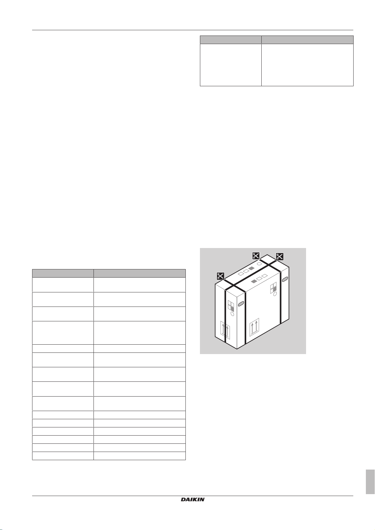
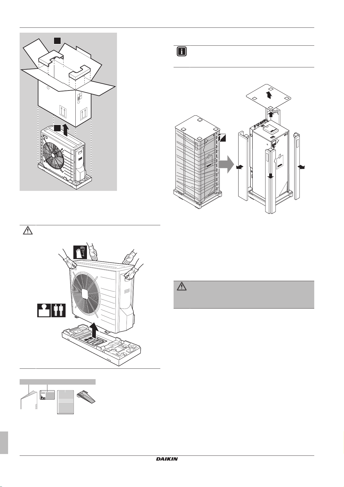
3.2.1 To unpack the outdoor unit
2.2 Installer reference guide at a glance
Chapter Description
General safety
precautions
About the documentation What documentation exists for the
About the box How to unpack the units and remove
About the units and
options
Application guidelines Various installation setups of the system
Preparation What to do and know before going
Installation What to do and know to install the
Configuration What to do and know to configure the
Commissioning What to do and know to commission the
Hand‑over to the user What to give and explain to the user
Maintenance and service How to maintain and service the units
Troubleshooting What to do in case of problems
Disposal How to dispose of the system
Technical data Specifications of the system
Glossary Definition of terms
Safety instructions that you must read
before installing
installer
their accessories
▪ How to identify the units
▪ Possible combinations of units and
options
on‑site
system
system after it is installed
system after it is configured
ERLQ004~008CA + EHVH04+08SU18+26CB6W
Daikin Altherma – Low temperature split
4P449978-1 – 2016.06
Installer reference guide
7
3 About the box
1
2
57kg
a db c
1× 1× 1× 2×
3.3 Indoor unit
INFORMATION
This unit has been tested and approved according to
BSEN12897:2006
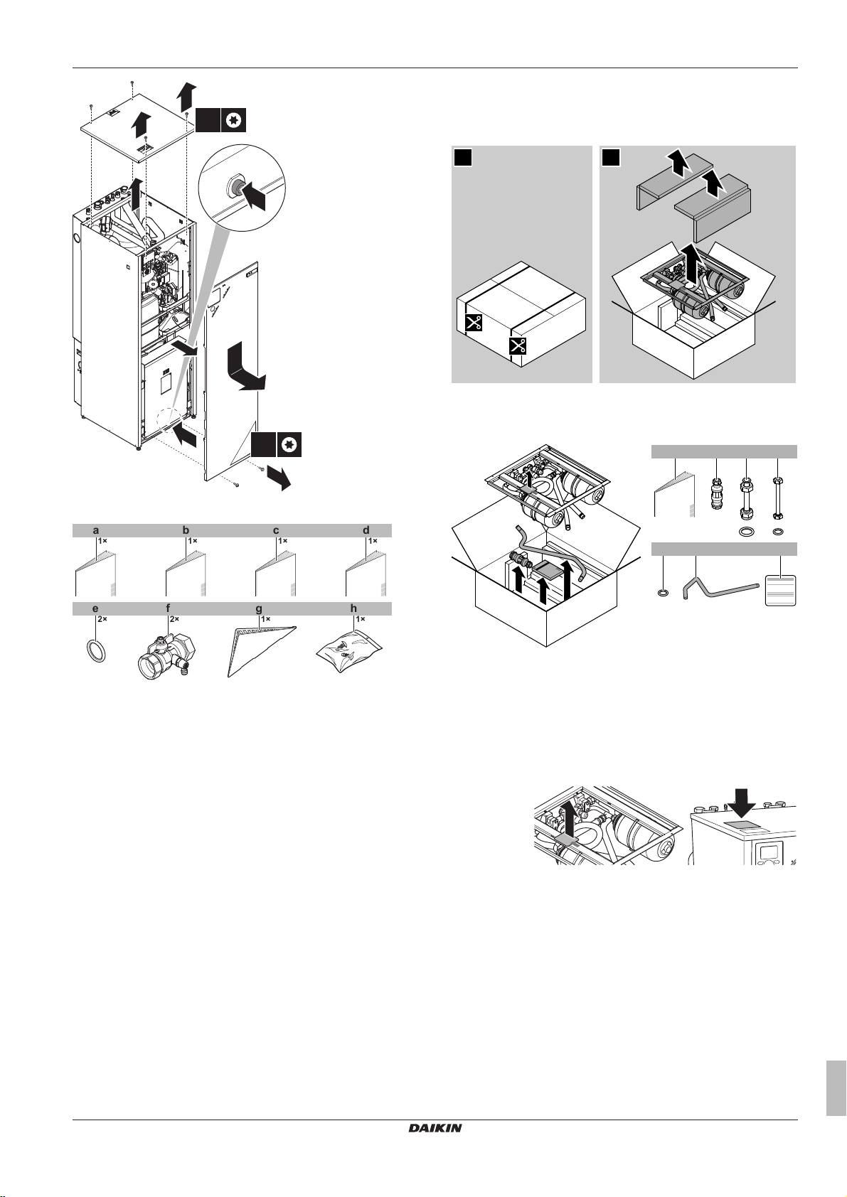
3.3.1 To unpack the indoor unit
3.2.2 To remove the accessories from the outdoor unit
1 Lift the outdoor unit.
CAUTION
Only handle the outdoor unit as follows:
3.3.2 To remove the accessories from the indoor unit
1 Remove the screws at the top of the unit.
2 Remove the top panel.
3 Remove the screws at the front of the unit.
4 Push on the button on the bottom of the front plate.
5 Remove the front plate.
WARNING: Sharp edges
Take the front plate on the upper part instead of the lower
part. Watch your fingers, there are sharp edges on the
lower part of the front plate.
2 Remove the accessories at the bottom of the package.
a Outdoor unit installation manual
b Fluorinated greenhouse gases label
c Multilingual fluorinated greenhouse gases label
Installer reference guide
d Unit mounting plate
8
ERLQ004~008CA + EHVH04+08SU18+26CB6W
Daikin Altherma – Low temperature split
4P449978-1 – 2016.06
4 About the units and options
a~e+h
g
f
5
4
1
2
3
4
4×
2×
1×
1× 1× 1× 1×
2× 1×2×
a b c d
f ge
h
21
1× 1× 2×
1×
a b c1×d
2× 1×
fe g
+ +
1
2
3.4 Domestic hot water tank kit
3.4.1 To unpack the domestic hot water tank kit
3.4.2 To remove the accessories from the domestic hot water tank kit
6 Remove the accessories.
a General safety precautions
b Addendum book for optional equipment
c Indoor unit installation manual
d Operation manual
e Sealing ring for shut-off valve
f Shut-off valve
g User interface cover
h 2 screws for fixing the user interface.
7 Reinstall the top panel and the front plate.
a Installation manual
b Tundish
c Water piping extension pieces for space heating IN and
OUT + sealings (38×27×2mm) (EKVSU260A only)
d Water piping extension piece for domestic hot water OUT +
sealing (24×17×2mm) (EKVSU260A only)
e Sealings for the flexible hoses of the domestic hot water
tank kit (24×17×2mm)
f Discharge pipe
g Identification label of the domestic hot water tank kit. Fix it
near the identification label of the indoor unit.
4 About the units and options
ERLQ004~008CA + EHVH04+08SU18+26CB6W
Daikin Altherma – Low temperature split
4P449978-1 – 2016.06
4.1 Overview: About the units and options
This chapter contains information about:
▪ Identifying the outdoor unit
▪ Identifying the indoor unit
▪ Combining outdoor and indoor units
▪ Combining the outdoor unit with options
▪ Combining the indoor unit with options
Installer reference guide
9
4 About the units and options
4.2 Identification
NOTICE
When installing or servicing several units at the same time,
make sure NOT to switch the service panels between
different models.
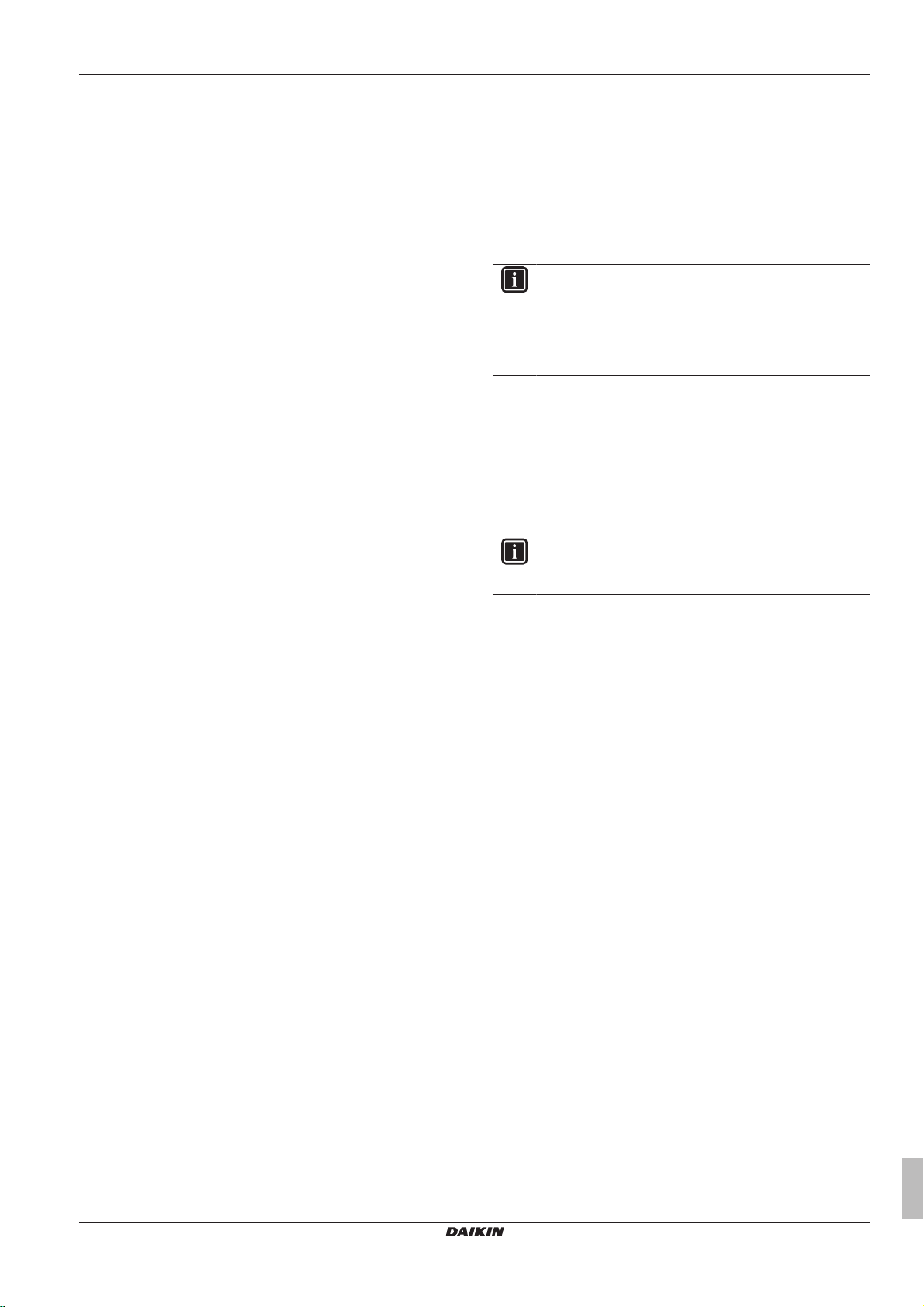
4.2.1 Identification label: Outdoor unit
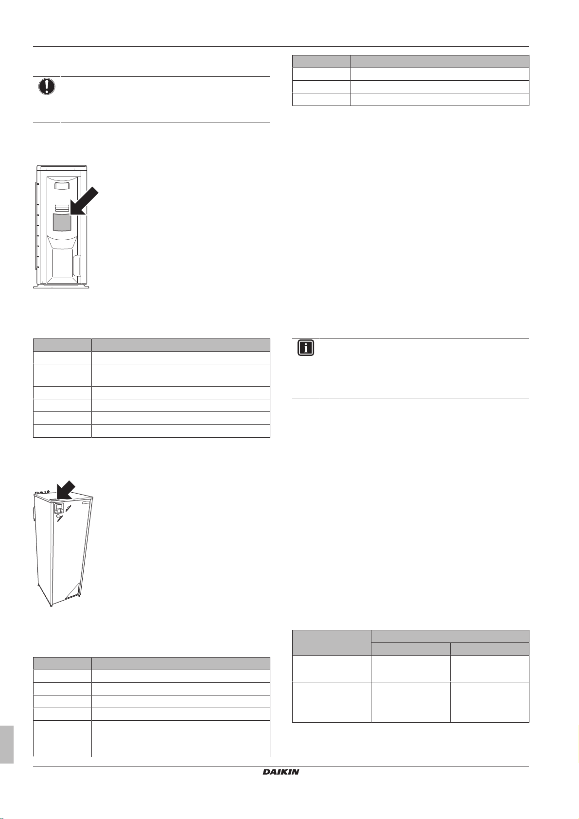
Location
Model identification
Example: ERLQ006CAV3
Code Explanation
ER European split outdoor pair heat pump
L Low water temperature – ambient zone: −10~
−20°C
Q Refrigerant R410A
006 Capacity class
CA Model series
V3 Power supply
4.2.2 Identification label: Indoor unit
Location
Code Description
18 Integrated tank volume
CB Model series
6W Backup heater model
4.3 Combining units and options
4.3.1 Possible options for the outdoor unit
Drain pan (EKDP008CA)
The drain pan is required to gather the drain from the outdoor unit.
The drain pan kit consists of:
▪ Drain pan
▪ Installation brackets
For installation instructions, see the installation manual of the drain
pan.
Drain pan heater (EKDPH008CA)
The drain pan heater is required to avoid freezing-up of the drain
pan.
It is recommended to install this option in colder regions with
possible low ambient temperatures or heavy snowfall.
For installation instructions, see the installation manual of the drain
pan heater.
INFORMATION
In case the drain pan heater is used, the jumper JP_DP on
the service PCB on the outdoor unit MUST be cut.
After cutting the jumper, you MUST reset the outdoor unit
to activate this function.
U-beams (EKFT008CA)
The U-beams are installation brackets on which the outdoor unit can
be installed.
It is recommended to install this option in colder regions with
possible low ambient temperatures or heavy snowfall.
For installation instructions, see the installation manual of the
outdoor unit.
Model identification
Example: EHVH04SU18CB6W
Code Description
E European model
HV Floor-standing indoor unit with integrated tank
H Heating only
04 Capacity class
SU Integrated tank material: Stainless steel
Model compatible with the G3 Building
Regulations in the UK.
Installer reference guide
10
4.3.2 Possible options for the indoor unit
Domestic hot water tank kit (EKVSU180+260A)
The domestic hot water tank kit makes it easier to comply with
section G3 of the Building Regulations in the UK. It contains the
following components:
▪ Pressure relief valve
▪ Pressure reducing valve
▪ Expansion vessels (1 and 2)
▪ Tundishes
Possible combinations of indoor unit and domestic hot water kit:
Indoor unit Domestic hot water kit
EKVSU180A EKVSU260A
EHVH04SU18CB6W
EHVH08SU18CB6W
EHVH08SU26CB6W
EHVH11SU26CB6W
EHVH16SU26CB6W
For installation instructions, see the installation manual of the
domestic hot water tank kit, or this installer reference guide.
O —
— O
ERLQ004~008CA + EHVH04+08SU18+26CB6W
Daikin Altherma – Low temperature split
4P449978-1 – 2016.06
4 About the units and options
User interface (EKRUCBL*)
The user interface and a possible additional user interface are
available as an option.
The additional user interface can be connected:
▪ To have both:
▪ control close to the indoor unit,
▪ room thermostat functionality in the principal space to be
heated.
▪ To have an interface containing other languages.
Following user interfaces are available:
▪ EKRUCBL1 contains following languages: German, French,
Dutch, Italian.
▪ EKRUCBL2 contains following languages: English, Swedish,
Norwegian, Finnish.
▪ EKRUCBL3 contains following languages: English, Spanish,
Greek, Portuguese.
▪ EKRUCBL4 contains following languages: English, Turkish,
Polish, Romanian.
▪ EKRUCBL5 contains following languages: German, Czech,
Slovenian, Slovakian.
▪ EKRUCBL6 contains following languages: English, Croatian,
Hungarian, Estonian.
▪ EKRUCBL7 contains following languages: English, German,
Russian, Danish.
Languages on the user interface can be uploaded by PC software or
copied from an user interface to the other.
For installation instructions, see "7.9.9 To connect the user
interface"on page45.
Simplified user interface (EKRUCBS)
▪ The simplified user interface can only be used in combination with
the main user interface.
▪ The simplified user interface acts as room thermostat and needs
to be installed in the room that you want it to control.
For installation instructions, see the installation and operation
manual of the simplified user interface.
Room thermostat (EKRTWA, EKRTR1, RTRNETA)
You can connect an optional room thermostat to the indoor unit. This
thermostat can either be wired (EKRTWA) or wireless (EKRTR1 and
RTRNETA). Thermostat RTRNETA can only be used in heating-only
systems.
For installation instructions, see the installation manual of the room
thermostat and addendum book for optional equipment.
Remote sensor for wireless thermostat (EKRTETS)
You can use a wireless indoor temperature sensor (EKRTETS) only
in combination with the wireless thermostat (EKRTR1).
For installation intructions, see the installation manual of the room
thermostat and addendum book for optional equipment.
Digital I/O PCB (EKRP1HB)
The digital I/O PCB is required to provide following signals:
▪ Alarm output
▪ Space heating On/OFF output
▪ Changeover to external heat source
For installation instructions, see the installation manual of the digital
I/O PCB and addendum book for optional equipment.
Demand PCB (EKRP1AHTA)
To enable the power saving consumption control by digital inputs
you must install the demand PCB.
For installation instructions, see the installation manual of the
demand PCB and addendum book for optional equipment.
Remote indoor sensor (KRCS01-1)
By default the internal user interface sensor will be used as room
temperature sensor.
As an option the remote indoor sensor can be installed to measure
the room temperature on another location.
For installation instructions, see the installation manual of the remote
indoor sensor and addendum book for optional equipment.
INFORMATION
▪ The remote indoor sensor can only be used in case the
user interface is configured with room thermostat
functionality.
▪ You can only connect either the remote indoor sensor
or the remote outdoor sensor.
Remote outdoor sensor (EKRSCA1)
By default the sensor inside the outdoor unit will be used to measure
the outdoor temperature.
As an option the remote outdoor sensor can be installed to measure
the outdoor temperature on another location (e.g. to avoid direct
sunlight) to have an improved system behaviour.
For installation instructions, see the installation manual of the remote
outdoor sensor.
INFORMATION
You can only connect either the remote indoor sensor or
the remote outdoor sensor.
PC configurator (EKPCCAB)
The PC cable makes a connection between the switch box of the
indoor unit and a PC. It gives the possibility to upload different
language files to the user interface and indoor parameters to the
indoor unit. For the available language files, contact your local
dealer.
The software and corresponding operating instructions are available
on http://www.daikineurope.com/support-and-manuals/software-
downloads/.
For installation instructions, see the installation manual of the PC
cable and "8Configuration"on page48.
Heat pump convector (FWXV)
For providing space heating, it is possible to use heat pump
convectors (FWXV).
For installation instructions, refer to the installation manual of the
heat pump convectors, and the addendum book for optional
equipment.
LAN adapter for smartphone control + Smart Grid applications
(BRP069A61)
You can install this LAN adapter to:
▪ Control the system via a smartphone app.
▪ Use the system in various Smart Grid applications.
For installation instructions, see the installation manual of the LAN
adapter.
LAN adapter for smartphone control (BRP069A62)
You can install this LAN adapter to control the system via a
smartphone app.
For installation instructions, see the installation manual of the LAN
adapter.
ERLQ004~008CA + EHVH04+08SU18+26CB6W
Daikin Altherma – Low temperature split
4P449978-1 – 2016.06
Installer reference guide
11
5 Application guidelines
B
A
a
4.3.3 Possible combinations of indoor unit and outdoor unit
Indoor unit Outdoor unit
ERLQ004CAV3 ERLQ006CAV3 ERLQ008CAV3
EHVH04SU18CB6W O — —
EHVH08SU18CB6W — O O
EHVH08SU26CB6W — O O
5 Application guidelines
5.1 Overview: Application guidelines
The purpose of the application guidelines is to give a glance of the
possibilities of the Daikin heatpump system.
NOTICE
▪ The illustrations in the application guidelines are meant
for reference only, and are NOT to be used as detailed
hydraulic diagrams. The detailed hydraulic
dimensioning and balancing are NOT shown, and are
the responsibility of the installer.
▪ For more information about the configuration settings to
optimize heatpump operation, see "8Configuration"on
page48.
This chapter contains application guidelines for:
▪ Setting up the space heating system
▪ Setting up an auxiliary heat source for space heating
▪ Setting up the domestic hot water tank
▪ Setting up the energy metering
▪ Setting up the power consumption
▪ Setting up an external temperature sensor
5.2 Setting up the space heating system
The Daikin heat pump system supplies leaving water to heat
emitters in one or more rooms.
Because the system offers a wide flexibility to control the
temperature in each room, you need to answer the following
questions first:
▪ How many rooms are heated by the Daikin heatpump system?
▪ Which heat emitter types are used in each room and what is their
design leaving water temperature?
Once the space heating requirements are clear, Daikin recommends
to follow the setup guidelines below.
NOTICE
If an external room thermostat is used, the external room
thermostat will control the room frost protection. However,
the room frost protection is only possible if the leaving
water temperature control on the unit's user interface is
turned ON.
INFORMATION
In case an external room thermostat is used and room frost
protection needs to be guaranteed in all conditions, then
you have to set auto emergency [A.6.C] to 1.
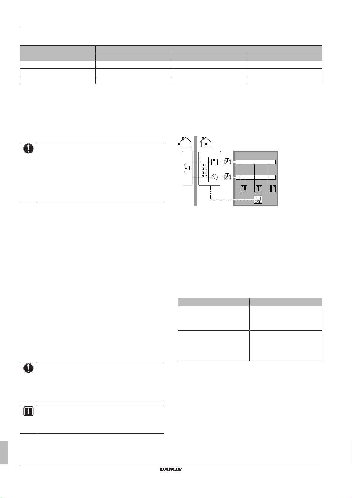
5.2.1 Single room
Underfloor heating or radiators – Wired room
thermostat
Setup
A Main leaving water temperature zone
B One single room
a User interface used as room thermostat
▪ The underfloor heating or radiators are directly connected to the
indoor unit.
▪ The room temperature is controlled by the user interface, which is
used as room thermostat. Possible installations:
▪ User interface installed in the room and used as room
thermostat
▪ User interface installed at the indoor unit and used for control
close to the indoor unit + user interface installed in the room
and used as room thermostat
Configuration
Setting Value
Unit temperature control:
▪ #: [A.2.1.7]
▪ Code: [C-07]
Number of water temperature
zones:
▪ #: [A.2.1.8]
▪ Code: [7-02]
Benefits
▪ Cost effective. You do NOT need an additional external room
thermostat.
▪ Highest comfort and efficiency. The smart room thermostat
functionality can decrease or increase the desired leaving water
temperature based on the actual room temperature (modulation).
This results in:
▪ Stable room temperature matching the desired temperature
(higher comfort)
▪ Less ON/OFF cycles (more quiet, higher comfort and higher
efficiency)
▪ Lowest possible leaving water temperature (higher efficiency)
2 (RT control): Unit operation is
decided based on the ambient
temperature of the user interface.
0 (1 LWT zone): Main
Installer reference guide
12
ERLQ004~008CA + EHVH04+08SU18+26CB6W
Daikin Altherma – Low temperature split
4P449978-1 – 2016.06
5 Application guidelines
B
A
b
a
B
A
a
▪ Easy. You can easily set the desired room temperature via the
user interface:
▪ For your daily needs, you can use preset values and schedules.
▪ To deviate from your daily needs, you can temporarily overrule
the preset values and schedules, use the holiday mode…
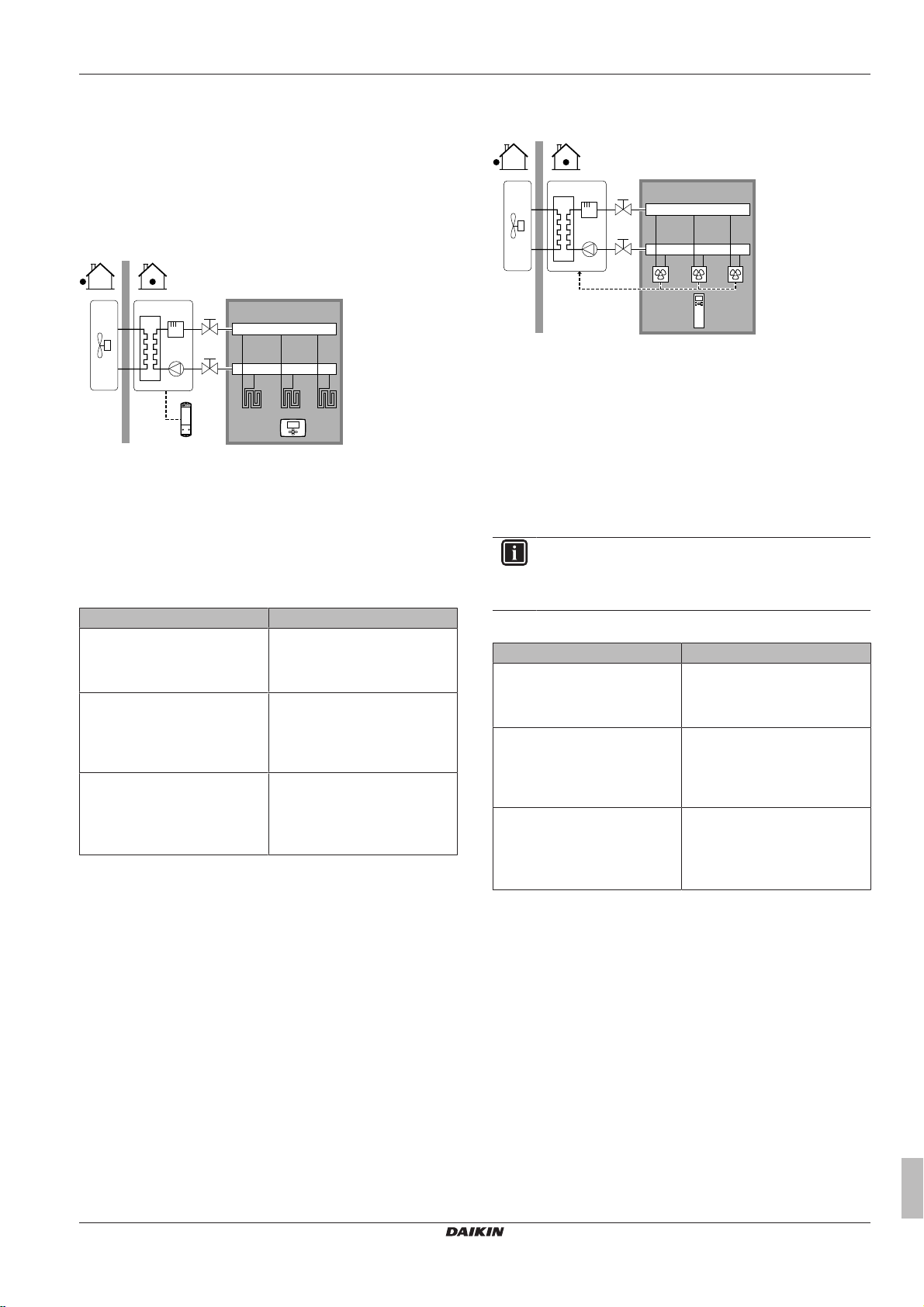
Underfloor heating or radiators – Wireless room
thermostat
Setup
A Main leaving water temperature zone
B One single room
a Receiver for wireless external room thermostat
b Wireless external room thermostat
▪ The underfloor heating or radiators are directly connected to the
indoor unit.
▪ The room temperature is controlled by the wireless external room
thermostat (optional equipment EKRTR1).
Configuration
Setting Value
Unit temperature control:
▪ #: [A.2.1.7]
▪ Code: [C-07]
Number of water temperature
zones:
▪ #: [A.2.1.8]
▪ Code: [7-02]
External room thermostat for the
main zone:
▪ #: [A.2.2.4]
▪ Code: [C-05]
Benefits
▪ Wireless. The Daikin external room thermostat is available in a
wireless version.
▪ Efficiency. Although the external room thermostat only sends ON/
OFF signals, it is specifically designed for the heatpump system.
1 (Ext RT control): Unit operation
is decided by the external
thermostat.
0 (1 LWT zone): Main
1 (Thermo ON/OFF): When the
used external room thermostat or
heatpump convector can only
send a thermo ON/OFF
condition.
Heatpump convectors
Setup
A Main leaving water temperature zone
B One single room
a Remote controller of the heatpump convectors
▪ The underfloor heating or radiators are directly connected to the
indoor unit.
▪ The desired room temperature is set via the remote controller of
the heatpump convectors.
▪ The space heating demand signal is sent to one digital input on
the indoor unit (X2M/1 and X2M/4).
▪ The space operation mode is sent to the heatpump convectors by
one digital output on the indoor unit (X2M/32 and X2M/33).
INFORMATION
When using multiple heat pump convectors, make sure
each one receives the infrared signal from the remote
controller of the heatpump convectors.
Configuration
Setting Value
Unit temperature control:
▪ #: [A.2.1.7]
▪ Code: [C-07]
Number of water temperature
zones:
▪ #: [A.2.1.8]
▪ Code: [7-02]
External room thermostat for the
main zone:
▪ #: [A.2.2.4]
▪ Code: [C-05]
Benefits
▪ Efficiency. Optimal energy efficiency because of the interlink
function.
▪ Stylish.
1 (Ext RT control): Unit operation
is decided by the external
thermostat.
0 (1 LWT zone): Main
1 (Thermo ON/OFF): When the
used external room thermostat or
heatpump convector can only
send a thermo ON/OFF
condition.
ERLQ004~008CA + EHVH04+08SU18+26CB6W
Daikin Altherma – Low temperature split
4P449978-1 – 2016.06
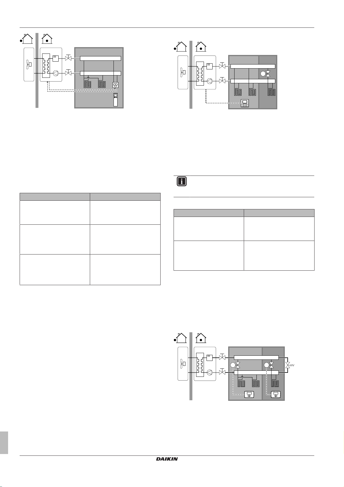
Combination: Underfloor heating + Heatpump
convectors
▪ Space heating is provided by:
▪ The underfloor heating
▪ The heatpump convectors
Setup
Installer reference guide
13
5 Application guidelines
B
A
a
T
B C
A
a
M2M1
B C
A
a a
b
Setup
A Main leaving water temperature zone
B One single room
a Remote controller of the heatpump convectors
▪ The heat pump convectors are directly connected to the indoor
unit.
▪ The desired room temperature is set via the remote controller of
the heatpump convectors.
▪ The space heating demand signal is sent to one digital input on
the indoor unit (X2M/1 and X2M/4)
▪ The space operation mode is sent to the heat pump convectors by
one digital output (X2M/32 and X2M/33) on the indoor unit.
Configuration
Setting Value
Unit temperature control:
▪ #: [A.2.1.7]
▪ Code: [C-07]
Number of water temperature
zones:
▪ #: [A.2.1.8]
▪ Code: [7-02]
External room thermostat for the
main zone:
▪ #: [A.2.2.4]
▪ Code: [C-05]
Benefits
▪ Efficiency. Under floor heating has the best performance with
Altherma LT.
▪ Comfort. The combination of the two heat emitter types provides
excellent heating comfort of the underfloor heating.
1 (Ext RT control): Unit operation
is decided by the external
thermostat.
0 (1 LWT zone): Main
1 (Thermo ON/OFF): When the
used external room thermostat or
heatpump convector can only
send a thermo ON/OFF
condition.
5.2.2 Multiple rooms – OneLWT zone
If only one leaving water temperature zone is needed because the
design leaving water temperature of all heat emitters is the same,
you do NOT need a mixing valve station (cost effective).
Example: If the heat pump system is used to heat up one floor
where all the rooms have the same heat emitters.
A Main leaving water temperature zone
B Room 1
C Room 2
a User interface
▪ The underfloor heating of the main room is directly connected to
the indoor unit.
▪ The room temperature of the main room is controlled by the user
interface used as thermostat.
▪ A thermostatic valve is installed before the underfloor heating in
each of the other rooms.
INFORMATION
Mind situations where the main room can be heated by
another heating source. Example: Fireplaces.
Configuration
Setting Value
Unit temperature control:
▪ #: [A.2.1.7]
▪ Code: [C-07]
Number of water temperature
zones:
▪ #: [A.2.1.8]
▪ Code: [7-02]
Benefits
▪ Cost effective.
▪ Easy. Same installation as for one room, but with thermostatic
valves.
2 (RT control): Unit operation is
decided based on the ambient
temperature of the user interface.
0 (1 LWT zone): Main
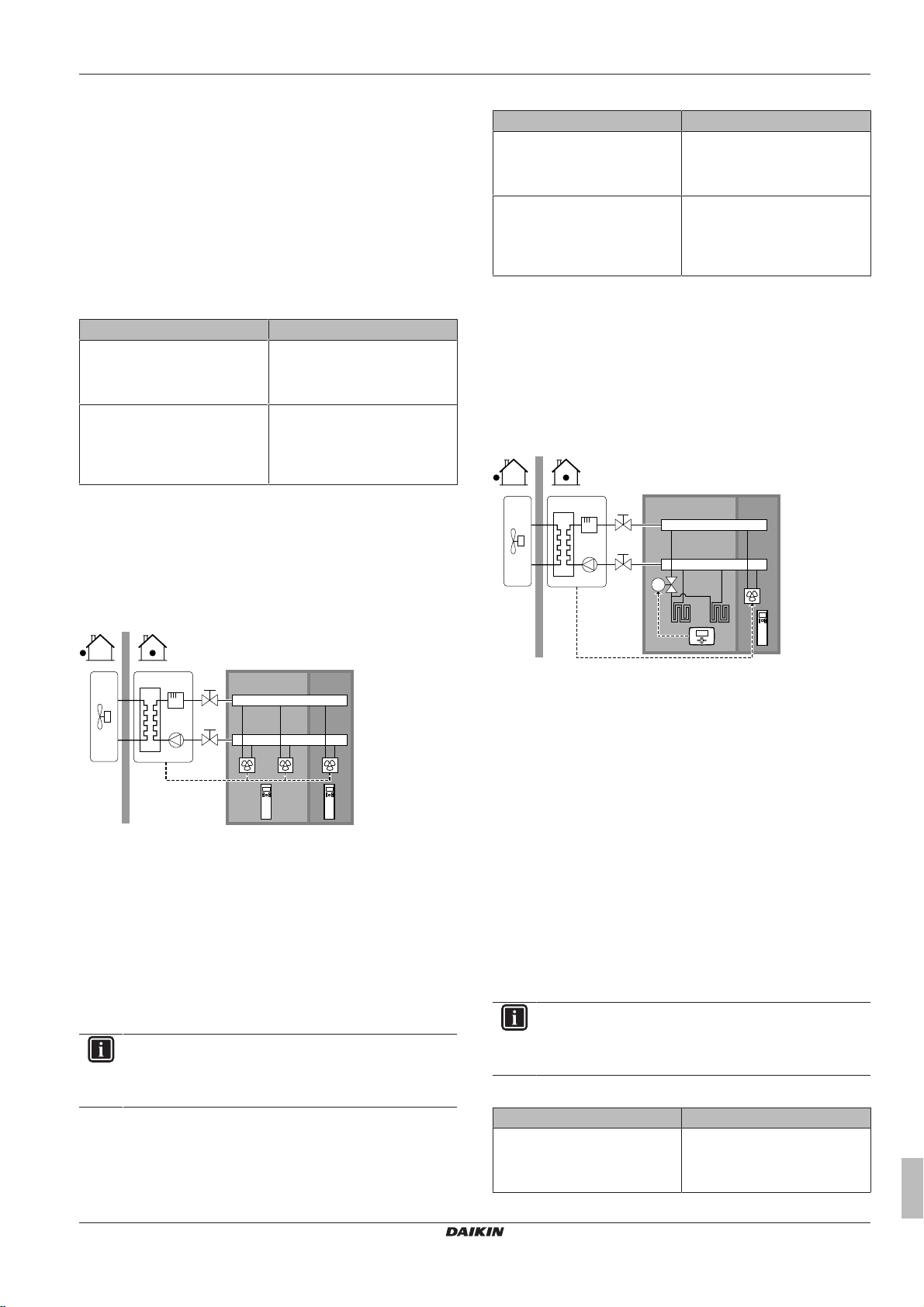
Underfloor heating or radiators – Multiple external
room thermostats
Setup
Underfloor heating or radiators – Thermostatic
valves
If you are heating up rooms with under floor heating or radiators, a
very common way is to control the temperature of the main room by
using a thermostat (this can either be the user interface or an
external room thermostat), while the other rooms are controlled by
so-called thermostatic valves, which open or close depending on the
room temperature.
Installer reference guide
14
A Main leaving water temperature zone
B Room 1
C Room 2
a External room thermostat
b Bypass valve
▪ For each room, a shut-off valve (field supplied) is installed to avoid
leaving water supply when there is no heating demand.
ERLQ004~008CA + EHVH04+08SU18+26CB6W
Daikin Altherma – Low temperature split
4P449978-1 – 2016.06
5 Application guidelines
B
A
a a
C
b
B C
A
a
M1
▪ A bypass valve must be installed to make water recirculation
possible when all shut-off valves are closed. To guarantee reliable
operation, provide a minimum water flow as described in table "To
check the water volume and flow rate" in "6.4 Preparing water
piping"on page25.
▪ The user interface connected to the indoor unit decides the space
operation mode. Mind that the operation mode on each room
thermostat must be set to match the indoor unit.
▪ The room thermostats are connected to the shut-off valves, but do
NOT have to be connected to the indoor unit. The indoor unit will
supply leaving water all the time, with the possibility to program a
leaving water schedule.
Configuration
Setting Value
Unit temperature control:
▪ #: [A.2.1.7]
▪ Code: [C-07]
Number of water temperature
zones:
▪ #: [A.2.1.8]
▪ Code: [7-02]
Benefits
Compared with underfloor heating or radiators for one room:
▪ Comfort. You can set the desired room temperature, including
schedules, for each room via the room thermostats.
0 (LWT control): Unit operation is
decided based on the leaving
water temperature.
0 (1 LWT zone): Main
Configuration
Setting Value
Unit temperature control:
▪ #: [A.2.1.7]
▪ Code: [C-07]
Number of water temperature
zones:
▪ #: [A.2.1.8]
▪ Code: [7-02]
Benefits
Compared with heatpump convectors for one room:
▪ Comfort. You can set the desired room temperature, including
schedules, for each room via the remote controller of the
heatpump convectors.
1 (Ext RT control): Unit operation
is decided by the external
thermostat.
0 (1 LWT zone): Main
Combination: Underfloor heating + Heatpump
convectors
Setup
Heatpump convectors
Setup
A Main leaving water temperature zone
B Room 1
C Room 2
a Remote controller of the heatpump convectors
▪ The desired room temperature is set via the remote controller of
the heatpump convectors.
▪ The user interface connected to the indoor unit decides the space
operation mode.
▪ The heating demand signals of each heat pump convector are
connected in parallel to the digital input on the indoor unit (X2M/1
and X2M/4). The indoor unit will only supply leaving water
temperature when there is an actual demand.
INFORMATION
To increase comfort and performance, Daikin recommends
to install the valve kit option EKVKHPC on each heatpump
convector.
A Main leaving water temperature zone
B Room 1
C Room 2
a External room thermostat
b Remote controller of the heatpump convectors
▪ For each room with heat pump convectors: The heat pump
convectors are directly connected to the indoor unit.
▪ For each room with under floor heating: A shut-off valve (field
supply) is installed before the underfloor heating. It prevents hot
water supply when the room has no heating demand.
▪ For each room with heat pump convectors: The desired room
temperature is set via the remote controller of the heat pump
convectors.
▪ For each room with under floor heating: The desired room
temperature is set via the external room thermostat (wired or
wireless).
▪ The user interface connected to the indoor unit decides the space
operation mode. Mind that the operation mode on each external
room thermostat and remote controller of the heat pump
convectors must be set to match the indoor unit.
INFORMATION
To increase comfort and performance, Daikin recommends
to install the valve kit option EKVKHPC on each heatpump
convector.
Configuration
Setting Value
Unit temperature control:
▪ #: [A.2.1.7]
▪ Code: [C-07]
0 (LWT control): Unit operation is
decided based on the leaving
water temperature.
ERLQ004~008CA + EHVH04+08SU18+26CB6W
Daikin Altherma – Low temperature split
4P449978-1 – 2016.06
Installer reference guide
15
5 Application guidelines
B
A
a a
C
E
D
b
c
d
Setting Value
Number of water temperature
0 (1 LWT zone): Main
zones:
▪ #: [A.2.1.8]
▪ Code: [7-02]
5.2.3 Multiple rooms – TwoLWT zones
If the heat emitters selected for each room are designed for different
leaving water temperatures, you can use different leaving water
temperature zones (maximum 2).
In this document:
▪ Main zone = Zone with the lowest design temperature
▪ Additional zone = The other zone
CAUTION
When there is more than one leaving water zone, you must
ALWAYS install a mixing valve station in the main zone to
decrease (in heating) the leaving water temperature when
the additional zone has demand.
Typical example:
Room (zone) Heat emitters: Design
Living room (main zone) Underfloor heating: 35°C
Bed rooms (additional zone) Heatpump convectors: 45°C
Setup
A Additional leaving water temperature zone
B Room 1
C Room 2
D Main leaving water temperature zone
E Room 3
a Remote controller of the heatpump convectors
b User interface
c Mixing valve station
d Pressure regulating valve
INFORMATION
A pressure regulating valve should be implemented before
the mixing valve station. This is to guarantee the correct
water flow balance between the main leaving water
temperature zone and the additional leaving water
temperature zone in relation to the required capacity of
both water temperature zones.
temperature
▪ For the main zone:
▪ A mixing valve station is installed before the underfloor heating.
▪ The pump of the mixing valve station is controlled by the ON/
OFF signal on the indoor unit (X2M/5 and X2M/7; normal closed
shut-off valve output).
▪ The room temperature is controlled by the user interface, which
is used as room thermostat.
▪ For the additional zone:
▪ The heatpump convectors are directly connected to the indoor
unit.
▪ The desired room temperature is set via the remote controller of
the heatpump convectors for each room.
▪ The heating demand signals of each heatpump convector are
connected in parallel to the digital input on the indoor unit
(X2M/1 and X2M/4). The indoor unit will only supply the desired
additional leaving water temperature when there is an actual
demand.
▪ The user interface connected to the indoor unit decides the space
operation mode. Mind that the operation mode on each remote
controller of the heatpump convectors must be set to match the
indoor unit.
Configuration
Setting Value
Unit temperature control:
▪ #: [A.2.1.7]
▪ Code: [C-07]
2 (RT control): Unit operation is
decided based on the ambient
temperature of the user interface.
Note:
▪ Main room = user interface
used as room thermostat
functionality
▪ Other rooms = external room
thermostat functionality
Number of water temperature
zones:
1 (2 LWT zones): Main +
additional
▪ #: [A.2.1.8]
▪ Code: [7-02]
In case of heatpump convectors:
External room thermostat for the
additional zone:
▪ #: [A.2.2.5]
1 (Thermo ON/OFF): When the
used external room thermostat or
heatpump convector can only
send a thermo ON/OFF
condition.
▪ Code: [C-06]
Shut-off valve output Set to follow the thermo demand
of the main zone.
At the mixing valve station Set the desired main leaving
water temperature.
Benefits
▪ Comfort.
▪ The smart room thermostat functionality can decrease or
increase the desired leaving water temperature based on the
actual room temperature (modulation).
▪ The combination of the two heat emitter systems provides the
excellent heating comfort of the under floor heating, and the
rapid air heat up of the heat pump convectors (e.g., living
room=under floor heating and the bedroom=convector (no
continuous heating)).
Installer reference guide
16
ERLQ004~008CA + EHVH04+08SU18+26CB6W
Daikin Altherma – Low temperature split
4P449978-1 – 2016.06
5 Application guidelines
a b c d e f
f
g h j
FHL1
FHL2
FHL3
M
h
i
il
k
m
n
o
L
N
H
Com
A
K2AK1A
X2M
B
TI
K2AK1A
Indoor/Auto/Boiler
1 2 3 4 X Y
Indoor
▪ Efficiency.
▪ Depending on the demand, the indoor unit supplies different
leaving water temperature matching the design temperature of
the different heat emitters.
▪ Underfloor heating has the best performance with Altherma LT.
5.3 Setting up an auxiliary heat source for space heating
▪ Space heating can be done by:
▪ The indoor unit
▪ An auxiliary boiler (field supply) connected to the system
▪ When the room thermostat requests heating, the indoor unit or the
auxiliary boiler starts operating depending on the outdoor
temperature (status of the changeover to external heat source).
When the permission is given to the auxiliary boiler, the space
heating by the indoor unit is turned OFF.
▪ Bivalent operation is only possible for space heating, NOT for
domestic hot water production. Domestic hot water is always
produced by the DHW tank connected to the indoor unit.
INFORMATION
▪ During heating operation of the heat pump, the
heat pump operates to achieve the desired
temperature set via the user interface. When weatherdependent operation is active, the water temperature is
determined automatically depending on the outdoor
temperature.
▪ During heating operation of the auxiliary boiler, the
auxiliary boiler operates to achieve the desired water
temperature set via the auxiliary boiler controller.
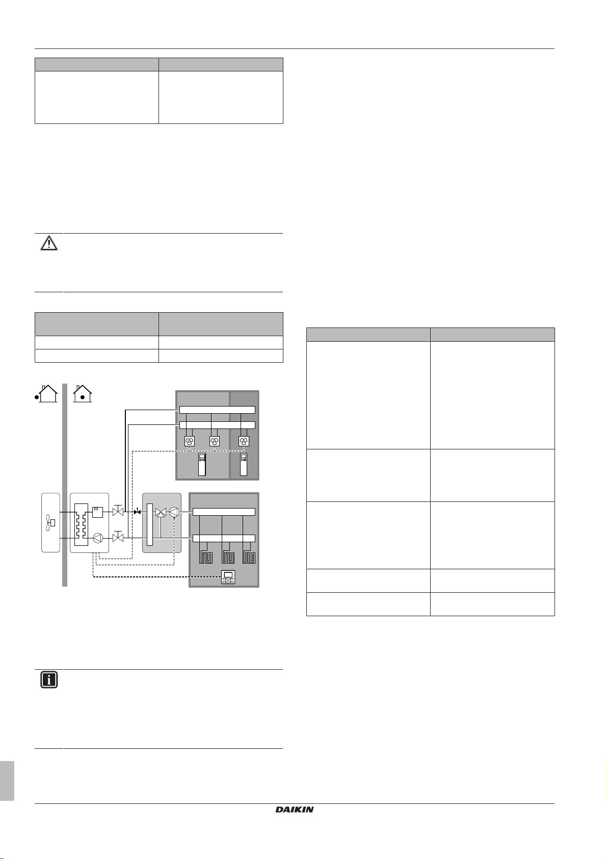
Setup
▪ Integrate the auxiliary boiler as follows:
n Heat exchanger coil
o Booster heater
FHL1...3 Underfloor heating
NOTICE
▪ Make sure the auxiliary boiler and its integration in the
system complies with applicable legislation.
▪ Daikin is NOT responsible for incorrect or unsafe
situations in the auxiliary boiler system.
▪ Make sure the return water to the heatpump does NOT exceed
55°C. To do so:
▪ Set the desired water temperature via the auxiliary boiler
controller to maximum 55°C.
▪ Install an aquastat valve in the return water flow of the
heatpump.
▪ Set the aquastat valve to close above 55°C and to open below
55°C.
▪ Install non-return valves.
▪ Make sure to only have one expansion vessel in the water circuit.
An expansion vessel is already premounted in the indoor unit.
▪ Install the digital I/O PCB (option EKRP1HB).
▪ Connect X1 and X2 (changeover to external heat source) on the
PCB to the auxiliary boiler thermostat.
▪ To setup the heat emitters, see "5.2Setting up the space heating
system"on page12.
Configuration
Via the user interface (quick wizard):
▪ Set the use of a bivalent system as external heat source.
▪ Set the bivalent temperature and hysteresis.
NOTICE
▪ Make sure the bivalent hysteresis has enough
differential to prevent frequent changeover between
indoor unit and auxiliary boiler.
▪ Because the outdoor temperature is measured by the
outdoor unit air thermistor, install the outdoor unit in the
shadow so that it is NOT influenced or turned ON/OFF
by direct sunlight.
▪ Frequent changeover may cause corrosion of the
auxiliary boiler. Contact the manufacturer of the
auxiliary boiler for more information.
ERLQ004~008CA + EHVH04+08SU18+26CB6W
Daikin Altherma – Low temperature split
4P449978-1 – 2016.06
a Outdoor unit
b Indoor unit
c Heat exchanger
d Backup heater
e Pump
f Shut-off valve
g Motorised 3‑way valve (delivered with DHW tank)
h Non-return valve (field supply)
i Shut-off valve (field supply)
j Collector (field supply)
k Auxiliary boiler (field supply)
l Aquastat valve (field supply)
m DHW tank
Changeover to external heat source decided by an auxiliary
contact
▪ Only possible in external room thermostat control AND one
leaving water temperature zone (see "5.2 Setting up the space
heating system"on page12).
▪ The auxiliary contact can be:
▪ An outdoor temperature thermostat
▪ An electricity tariff contact
▪ A manually operated contact
▪ …
▪ Setup: Connect the following field wiring:
Installer reference guide
17
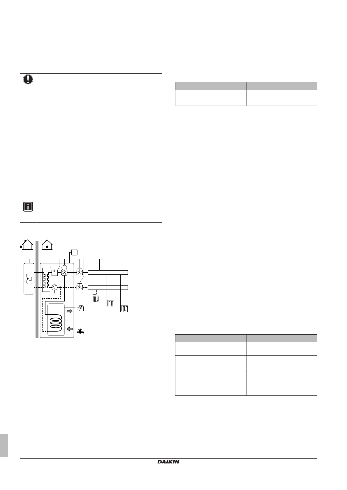
5 Application guidelines
FHL1
FHL2
FHL3
M
UI
a b c d hh if
e
g
j
BTIBoiler thermostat input
A Auxiliary contact (normal closed)
H Heating demand room thermostat (optional)
K1A Auxiliary relay for activation of indoor unit (field supply)
K2A Auxiliary relay for activation of boiler (field supply)
Indoor Indoor unit
Auto Automatic
Boiler Boiler
NOTICE
▪ Make sure the auxiliary contact has enough differential
or time delay to prevent frequent changeover between
indoor unit and auxiliary boiler.
▪ If the auxiliary contact is an outdoor temperature
thermostat, install the thermostat in the shadow so that
it is NOT influenced or turned ON/OFF by direct
sunlight.
▪ Frequent changeover may cause corrosion of the
auxiliary boiler. Contact the manufacturer of the
auxiliary boiler for more information.
5.4 Setting up the domestic hot water tank
The DHW tank is integrated in the indoor unit, and contains a 2.4kW
booster heater. The booster heater contains 2 safeties: a thermal
cut-out and a thermal fuse. If a certain temperature is exceeded, the
safeties deactivate the booster heater.
INFORMATION
The non-self-resetting thermal cut-out of the booster heater
is set below 89°C.
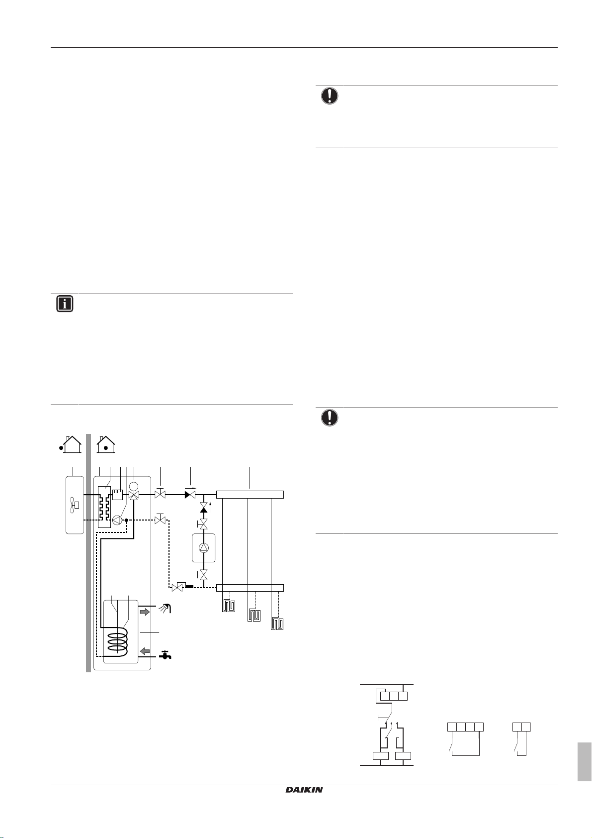
5.4.1 System layout – Integrated DHW tank
Selecting the volume and desired temperature for the DHW tank
consists of:
1 Determining the DHW consumption (equivalent hot water
volume at 40°C).
2 Determining the volume and desired temperature for the DHW
tank.
Possible DHW tank volumes
Type Possible volumes
Integrated DHW tank ▪ 180l
▪ 260l
Energy saving tips
▪ If the DHW consumption differs from day to day, you can program
a weekly schedule with different desired DHW tank temperatures
for each day.
▪ The lower the desired DHW tank temperature, the more cost
effective. By selecting a larger DHW tank, you can lower the
desired DHW tank temperature.
▪ The heatpump itself can produce domestic hot water of maximum
55°C (50°C if outdoor temperature is low). The electrical
resistance integrated in the DHW tank (booster heater) can
increase this temperature. However, this consumes more energy.
Daikin recommends to set the desired DHW tank temperature
below 55°C to avoid using the electrical resistance.
The booster heater:
▪ Is used as emergency heater.
▪ Is used when the disinfection function for the DHW tank is
active.
▪ Can assist during defrost operation for the outdoor unit.
▪ The higher the outdoor temperature, the better the performance of
the heatpump.
▪ If energy prices are the same during the day and the night,
Daikin recommends to heat up the DHW tank during the day.
▪ If energy prices are lower during the night, Daikin recommends
to heat up the DHW tank during the night.
▪ When the heatpump produces domestic hot water, it cannot heat
up a space. When you need domestic hot water and space
heating at the same, Daikin recommends to produce the domestic
hot water during the night when there is lower space heating
demand.
Determining the DHW consumption
Answer the following questions and calculate the DHW consumption
(equivalent hot water volume at 40°C) using the typical water
volumes:
a Outdoor unit
b Indoor unit
c Heat exchanger
d Backup heater
e Pump
f Motorised 3‑way valve
g DHW tank
h Shut-off valve
i Collector (field supply)
j Booster heater
FHL1...3 Underfloor heating
UI User interface
5.4.2 Selecting the volume and desired temperature for the DHW tank
People experience water as hot when its temperature is 40°C.
Therefore, the DHW consumption is always expressed as equivalent
hot water volume at 40°C. However, you can set the DHW tank
temperature at a higher temperature (example: 53°C), which is then
mixed with cold water (example: 15°C).
Installer reference guide
18
Question Typical water volume
How many showers are needed
per day?
How many baths are needed per
1shower = 10min×10l/min =
100l
1bath = 150l
day?
How much water is needed at the
1sink = 2min×5l/min = 10l
kitchen sink per day?
Are there any other domestic hot
—
water needs?
Example: If the DHW consumption of a family (4 persons) per day is
as follows:
▪ 3 showers
▪ 1 bath
▪ 3 sink volumes
Then the DHW consumption = (3×100l)+(1×150l)+(3×10l)=480l
ERLQ004~008CA + EHVH04+08SU18+26CB6W
Daikin Altherma – Low temperature split
4P449978-1 – 2016.06
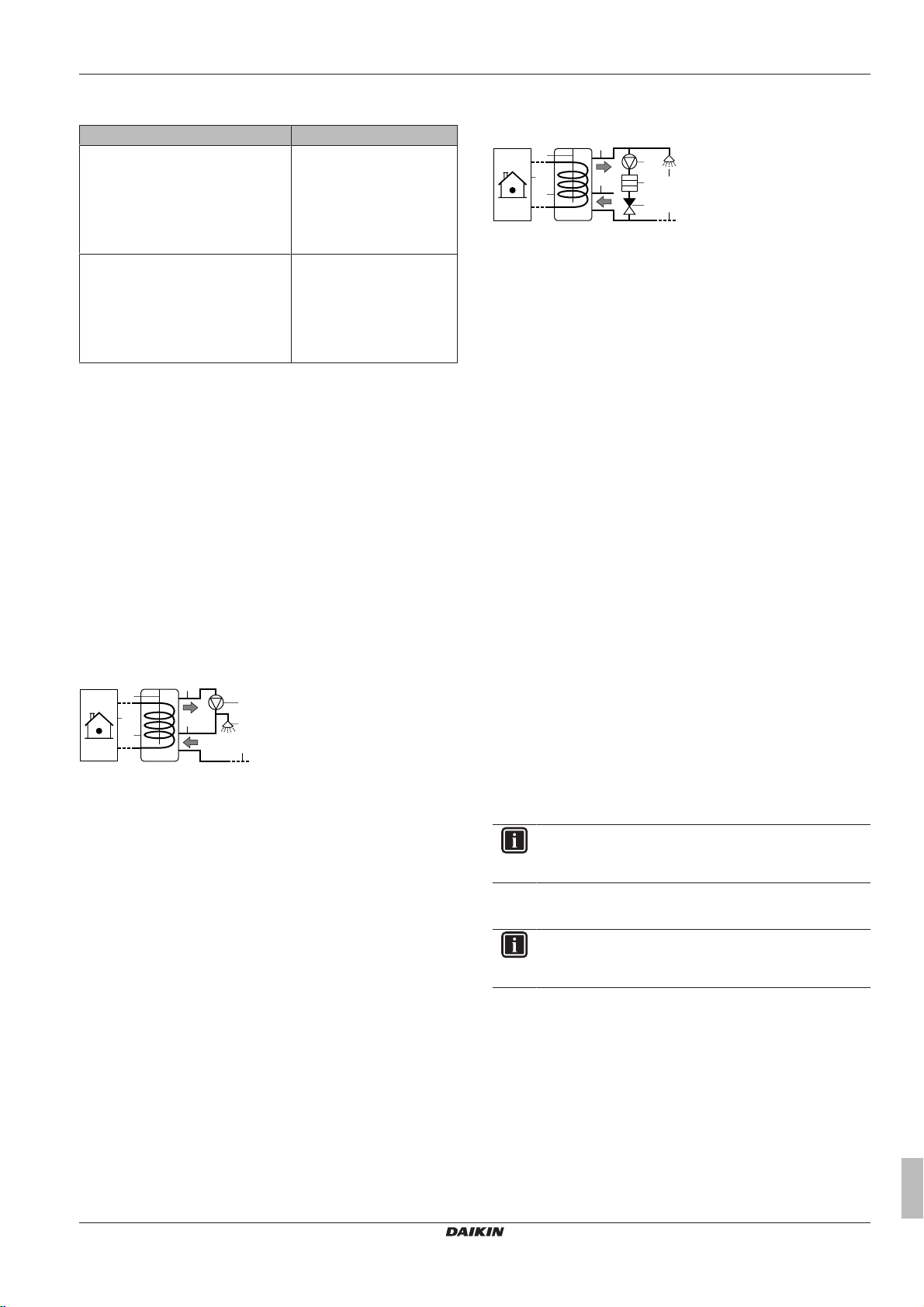
5 Application guidelines
c
f
a
b
j
g
h
i
c
a
d f
e g
h
i
b
j
Determining the volume and desired temperature for the DHW
tank
Formula Example
V1=V2+V2×(T2−40)/(40−T1) If:
▪ V2=180l
▪ T2=54°C
▪ T1=15°C
Then V1=280l
V2=V1×(40−T1)/(T2−T1) If:
▪ V1=480l
▪ T2=54°C
▪ T1=15°C
Then V2=307l
V1DHW consumption (equivalent hot water volume at 40°C)
V2Required DHW tank volume if only heated once
T2DHW tank temperature
T1Cold water temperature
5.4.3 Setup and configuration – DHW tank
▪ For large DHW consumptions, you can heat up the DHW tank
several times during the day.
▪ To heat up the DHW tank to the desired DHW tank temperature,
you can use the following energy sources:
▪ Thermodynamic cycle of the heatpump
▪ Booster heater
▪ For more information about optimizing the energy consumption for
producing domestic hot water, see "8Configuration"on page48.
5.4.4 DHW pump for instant hot water
Setup
a Indoor unit
b DHW tank
c DHW pump (field supply)
f Shower (field supply)
g Cold water
h Domestic hot water OUT
i Recirculation connection
j Booster heater
▪ By connecting a DHW pump, instant hot water can be available at
the tap.
▪ The DHW pump and the installation are field supply and the
responsibility of the installer.
▪ For more information about connecting the recirculation
connection: see "7Installation"on page29.
Configuration
▪ For more information, see "8Configuration"on page48.
▪ You can program a schedule to control the DHW pump via the
user interface. For more information, see the user reference
guide.
5.4.5 DHW pump for disinfection
Setup
a Indoor unit
b DHW tank
c DHW pump (field supply)
d Heater element (field supply)
e Non‑return valve (field supply)
f Shower (field supply)
g Cold water
h Domestic hot water OUT
i Recirculation connection
j Booster heater
▪ The DHW pump is field-supplied and its installation is the
responsibility of the installer.
▪ The temperature of the DHW tank can be set to maximum 65°C. If
applicable legislation requires higher temperature for disinfection,
you can connect a DHW pump and heater element as shown
above.
▪ If applicable legislation requires disinfection of the water piping
until the tapping point, you can connect a DHW pump and heater
element (if needed) as shown above.
Configuration
The indoor unit can control DHW pump operation. For more
information, see "8Configuration"on page48.
5.5 Setting up the energy metering
▪ Via the user interface, you can read out the following energy data:
▪ Produced heat
▪ Consumed energy
▪ You can read out the energy data:
▪ For space heating
▪ For domestic hot water production
▪ You can read out the energy data:
▪ Per month
▪ Per year
INFORMATION
The calculated produced heat and consumed energy are
an estimation, the accuracy cannot be guaranteed.
5.5.1 Produced heat
INFORMATION
The sensors used to calculate the produced heat are
calibrated automatically.
▪ Applicable for all models.
▪ The produced heat is calculated internally based on:
▪ The leaving and entering water temperature
▪ The flow rate
▪ The power consumption of the booster heater in the domestic
hot water tank
Daikin Altherma – Low temperature split
4P449978-1 – 2016.06
ERLQ004~008CA + EHVH04+08SU18+26CB6W
Installer reference guide
19
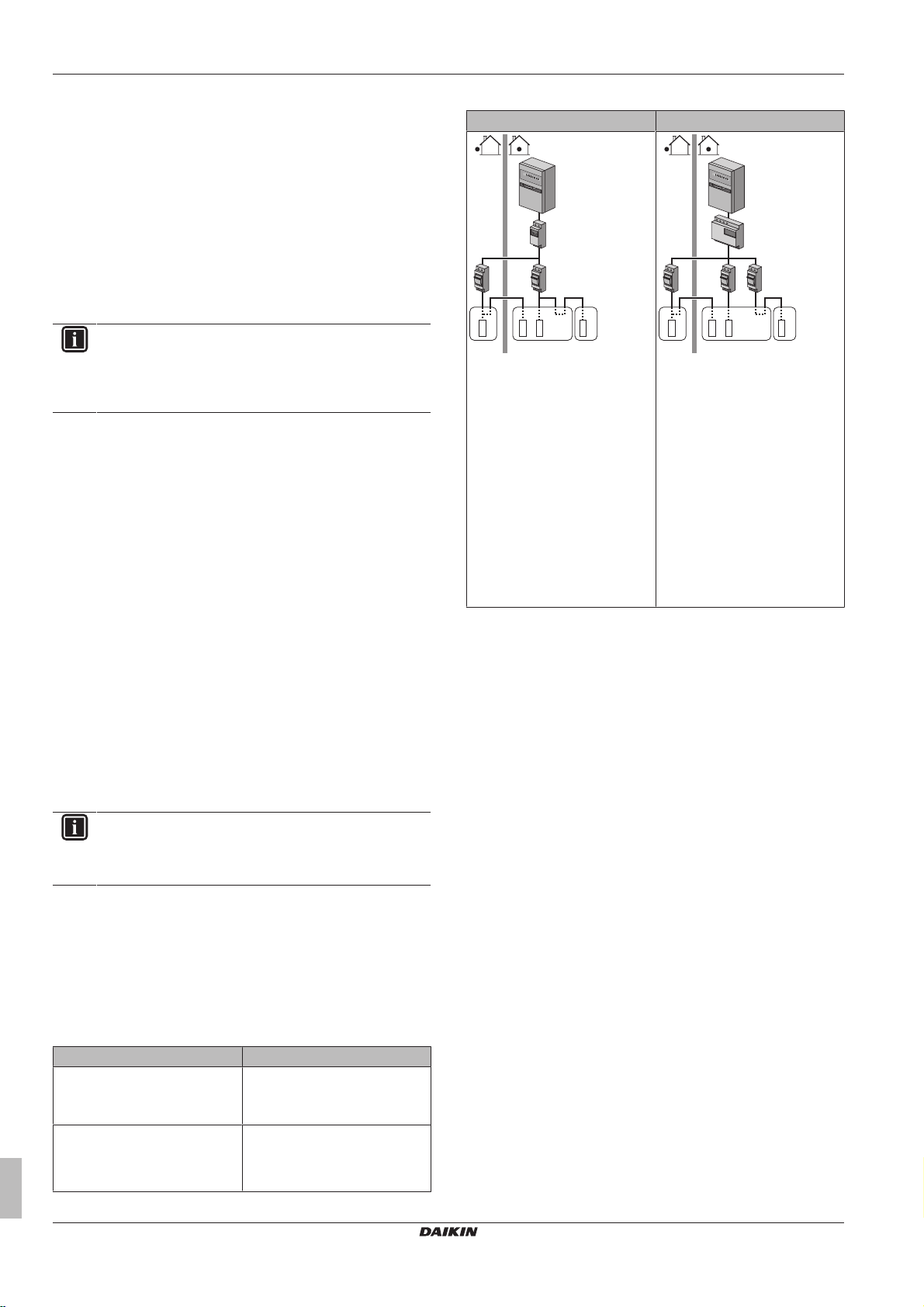
5 Application guidelines
b
5
8
0
1
5
0
0
0
c c
fed
g
A B C
a
b
5
8
0
1
5
0
0
0
gfe
h
A B C
c c d
a
▪ Setup and configuration:
▪ No additional equipment needed.
▪ Measure the capacity (resistance measurement) of the booster
heater and set the capacity via the user interface. Example: If
you measure a booster heater resistance of 24Ω, the capacity
of the heater at 230V is 2200W.
5.5.2 Consumed energy
You can use the following methods to determine the consumed
energy:
▪ Calculating
▪ Measuring
INFORMATION
You cannot combine calculating the consumed energy
(example: for backup heater) and measuring the
consumed energy (example: for outdoor unit). If you do so,
the energy data will be invalid.
Calculating the consumed energy
▪ Only applicable for EHVH04+08.
▪ The consumed energy is calculated internally based on:
▪ The actual power input of the outdoor unit
▪ The set capacity of the backup heater and booster heater
▪ The voltage
▪ Setup and configuration: To get accurate energy data, measure
the capacity (resistance measurement) and set the capacity via
the user interface for:
▪ The backup heater (step1 and step2)
▪ The booster heater
Measuring the consumed energy
▪ Applicable for all models.
▪ Preferred method because of higher accuracy.
▪ Requires external power meters.
▪ Setup and configuration: When using electrical power meters, set
the number of pulses/kWh for each power meter via the user
interface. Consumed energy data for EHVH11+16 models will only
be available if this setting is configured.
INFORMATION
When measuring the electrical power consumption, make
sure ALL power input of the system is covered by the
electrical power meters.
5.5.3 Normal kWh rate power supply
General rule
One power meter that covers the entire system is sufficient.
Setup
Connect the power meter to X5M/7 and X5M/8.
Power meter type
In case of… Use a… power meter
▪ Single-phase outdoor unit
▪ Backup heater supplied from a
single-phase grid
In other cases (i.e. a three-phase
outdoor unit and/or a backup
heater connected to a threephase grid)
Single-phase
Three-phase
Example
Single-phase power meter Three-phase power meter
A Outdoor unit
B Indoor unit
C DHW tank
a Electrical cabinet (L1/N)
b Power meter (L1/N)
c Fuse (L1/N)
d Outdoor unit (L1/N)
e Indoor unit (L1/N)
f Backup heater (L1/N)
g Booster heater (L1/N)
A Outdoor unit
B Indoor unit
C DHW tank
a Electrical cabinet (L1/L2/L3/N)
b Power meter (L1/L2/L3/N)
c Fuse (L1/L2/L3/N)
d Fuse (L1/N)
e Outdoor unit (L1/L2/L3/N)
f Indoor unit (L1/L2/L3/N)
g Backup heater (L1/L2/L3/N)
h Booster heater (L1/N)
Exception
▪ You can use a second power meter if:
▪ The power range of one meter is insufficient.
▪ The electrical meter cannot easily be installed in the electrical
cabinet.
▪ 230 V and 400 V three-phase grids are combined (very
uncommon), because of technical limitations of power meters.
▪ Connection and setup:
▪ Connect the second power meter to X5M/9 and X5M/10.
▪ In the software the power consumption data of both meters is
added so you do NOT have to set which meter covers which
power consumption. You only need to set the number of pulses
of each power meter.
▪ See "5.5.4 Preferential kWh rate power supply" on page20 for
an example with two power meters.
5.5.4 Preferential kWh rate power supply
General rule
▪ Power meter1: Measures the outdoor unit.
▪ Power meter2: Measures the rest (i.e. indoor unit, backup heater,
and booster heater).
Setup
▪ Connect power meter1 to X5M/7 and X5M/8.
▪ Connect power meter2 to X5M/9 and X5M/10.
Power meter types
▪ Power meter1: Single- or three-phase power meter according to
the power supply of the outdoor unit.
Installer reference guide
20
ERLQ004~008CA + EHVH04+08SU18+26CB6W
Daikin Altherma – Low temperature split
4P449978-1 – 2016.06

▪ Power meter2:
e efe
ihg
j
A B C
b
a
d
c
5
8
0
1
5
0
0
0
5
8
0
1
5
0
0
0
P
i
t
DI
a
b
a
b
c
A B C
D
1
2
3
4
5
A8P
▪ In case of a single-phase backup heater configuration, use a
single-phase power meter.
▪ In other cases, use a three-phase power meter.
Example
Single-phase outdoor unit with a three-phase backup heater:
A Outdoor unit
B Indoor unit
C DHW tank
a Electrical cabinet (L1/N): Preferential kWh rate power
supply
b Electrical cabinet (L1/L2/L3/N): Normal kWh rate power
supply
c Power meter (L1/N)
d Power meter (L1/L2/L3/N)
e Fuse (L1/N)
f Fuse (L1/L2/L3/N)
g Outdoor unit (L1/N)
h Indoor unit (L1/N)
i Backup heater (L1/L2/L3/N)
j Booster heater (L1/N)
5.6 Setting up the power consumption control
▪ The power consumption control:
▪ Is only applicable for EHVH04+08.
▪ Allows you to limit the power consumption of the entire system
(sum of outdoor unit, indoor unit, booster heater, and backup
heater).
▪ Configuration: Set the power limitation level and how it has to
be achieved via the user interface.
▪ The power limitation level can be expressed as:
▪ Maximum running current (inA)
▪ Maximum power input (inkW)
▪ The power limitation level can be activated:
▪ Permanently
▪ By digital inputs
5 Application guidelines
PiPower input
t Time
DI Digital input (power limitation level)
a Power limitation active
b Actual power input
Setup and configuration
▪ No additional equipment needed.
▪ Set the power consumption control settings in [A.6.3.1] via the
user interface (for the description of all settings, see
"8Configuration"on page48):
▪ Select full time limitation mode
▪ Select the type of limitation (power in kW or current in A)
▪ Set the desired power limitation level
NOTICE
Mind the following guidelines when selecting the desired
power limitation level:
▪ Set a minimum power consumption of ±3.6 kW to
guarantee defrost operation. Otherwise, if defrosting is
interrupted several times, the heat exchanger will
freeze up.
▪ Set a minimum power consumption of ±3 kW to
guarantee space heating and DHW production by
allowing at least one electrical heater (backup heater
step1 or booster heater).
5.6.2 Power limitation activated by digital inputs
Power limitation is also useful in combination with an energy
management system.
The power or current of the entire Daikin system is limited
dynamically by digital inputs (maximum four steps). Each power
limitation level is set via the user interface by limiting one of the
following:
▪ Current (in A)
▪ Power input (in kW)
The energy management system (field supply) decides the activation
of a certain power limitation level. Example: To limit the maximum
power of the entire house (lighting, domestic appliances, space
heating…).
5.6.1 Permanent power limitation
Permanent power limitation is useful to assure a maximum power or
current input of the system. In some countries, legislation limits the
maximum power consumption for space heating and DHW
production.
ERLQ004~008CA + EHVH04+08SU18+26CB6W
Daikin Altherma – Low temperature split
4P449978-1 – 2016.06
A Outdoor unit
B Indoor unit
C DHW tank
D Energy management system
a Power limitation activation (4 digital inputs)
b Backup heater
c Booster heater
Installer reference guide
21
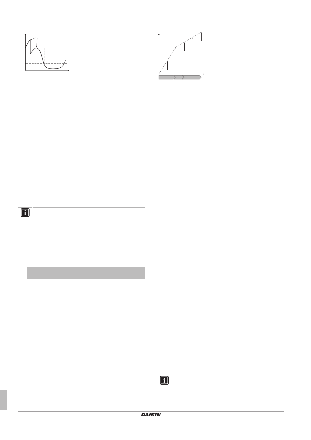
P
i
t
DI4
DI3
DI1
a
b
P
h
C
e
a
b
c
d
e
A B C
5 Application guidelines
PiPower input
t Time
DI Digital inputs (power limitation levels)
a Power limitation active
b Actual power input
Setup
▪ Demand PCB (option EKRP1AHTA) needed.
▪ Maximum four digital inputs are used to activate the
corresponding power limitation level:
▪ DI1 = weakest limitation (highest energy consumption)
▪ DI4 = strongest limitation (lowest energy consumption)
▪ For the specifications of the digital inputs, and for where to
connect them, refer to the wiring diagram.
Configuration
Set the power consumption control settings in [A.6.3.1] via the user
interface (for the description of all settings, see "8Configuration"on
page48):
▪ Select activation by digital inputs.
▪ Select the type of limitation (power in kW or current in A).
▪ Set the desired power limitation level corresponding to each digital
input.
INFORMATION
In case more than 1 digital input is closed (at the same
time), the digital input priority is fixed: DI4 priority>…>DI1.
5.6.3 Power limitation process
The outdoor unit has better efficiency than the electrical heaters.
Therefore, the electrical heaters are limited and turned OFF first.
The system limits power consumption in the following order:
1 Limits certain electrical heaters.
If… has priority Then set the heater priority
Domestic hot water production Booster heater.
Space heating Backup heater.
2 Turns OFF all electrical heaters.
3 Limits the outdoor unit.
4 Turns OFF the outdoor unit.
Example
If the configuration is as follows:
▪ Power limitation level does NOT allow operation of both booster
heater and backup heater (step1 and step2).
▪ Heater priority = Booster heater.
Then power consumption is limited as follows:
Installer reference guide
22
via the user interface to…
Result: The backup heater will
be turned OFF first.
Result: The booster heater will
be turned OFF first.
PhProduced heat
CeConsumed energy
A Outdoor unit
B Booster heater
C Backup heater
a Limited outdoor unit operation
b Full outdoor unit operation
c Booster heater turned ON
d Backup heater step1 turned ON
e Backup heater step2 turned ON
5.7 Setting up an external temperature sensor
You can connect one external temperature sensor. It can measure
the indoor or outdoor ambient temperature. Daikin recommends to
use an external temperature sensor in the following cases:
Indoor ambient temperature
▪ In room thermostat control, the user interface is used as room
thermostat and it measures the indoor ambient temperature.
Therefore, the user interface must be installed on a location:
▪ Where the average temperature in the room can be detected
▪ That is NOT exposed to direct sunlight
▪ That is NOT near a heat source
▪ That is NOT affected by outside air or air draught because of,
for example, door opening/closing
▪ If this is NOT possible, Daikin recommends to connect a remote
indoor sensor (option KRCS01-1).
▪ Setup: For installation instructions, see the installation manual of
the remote indoor sensor.
▪ Configuration: Select room sensor [A.2.2.B].
Outdoor ambient temperature
▪ In the outdoor unit, the outdoor ambient temperature is measured.
Therefore, the outdoor unit must be installed on a location:
▪ At the north side of the house or at the side of the house where
the most heat emitters are located
▪ That is NOT exposed to direct sunlight
▪ If this is NOT possible, Daikin recommends to connect a remote
outdoor sensor (option EKRSCA1).
▪ Setup: For installation instructions, see the installation manual of
the remote outdoor sensor.
▪ Configuration: Select outdoor sensor [A.2.2.B].
▪ During suspend (see "8Configuration"on page48), the outdoor
unit is turned down to reduce the standby energy losses. As a
result, the outdoor ambient temperature is NOT read out.
▪ If the desired leaving water temperature is weather dependent, the
full time outdoor temperature measurement is important. This is
another reason to install the optional outdoor ambient temperature
sensor.
INFORMATION
The external outdoor ambient sensor data (either averaged
or instantaneous) is used in the weather-dependent control
curves. To protect the outdoor unit, the internal sensor of
the outdoor unit is always used.
ERLQ004~008CA + EHVH04+08SU18+26CB6W
Daikin Altherma – Low temperature split
4P449978-1 – 2016.06
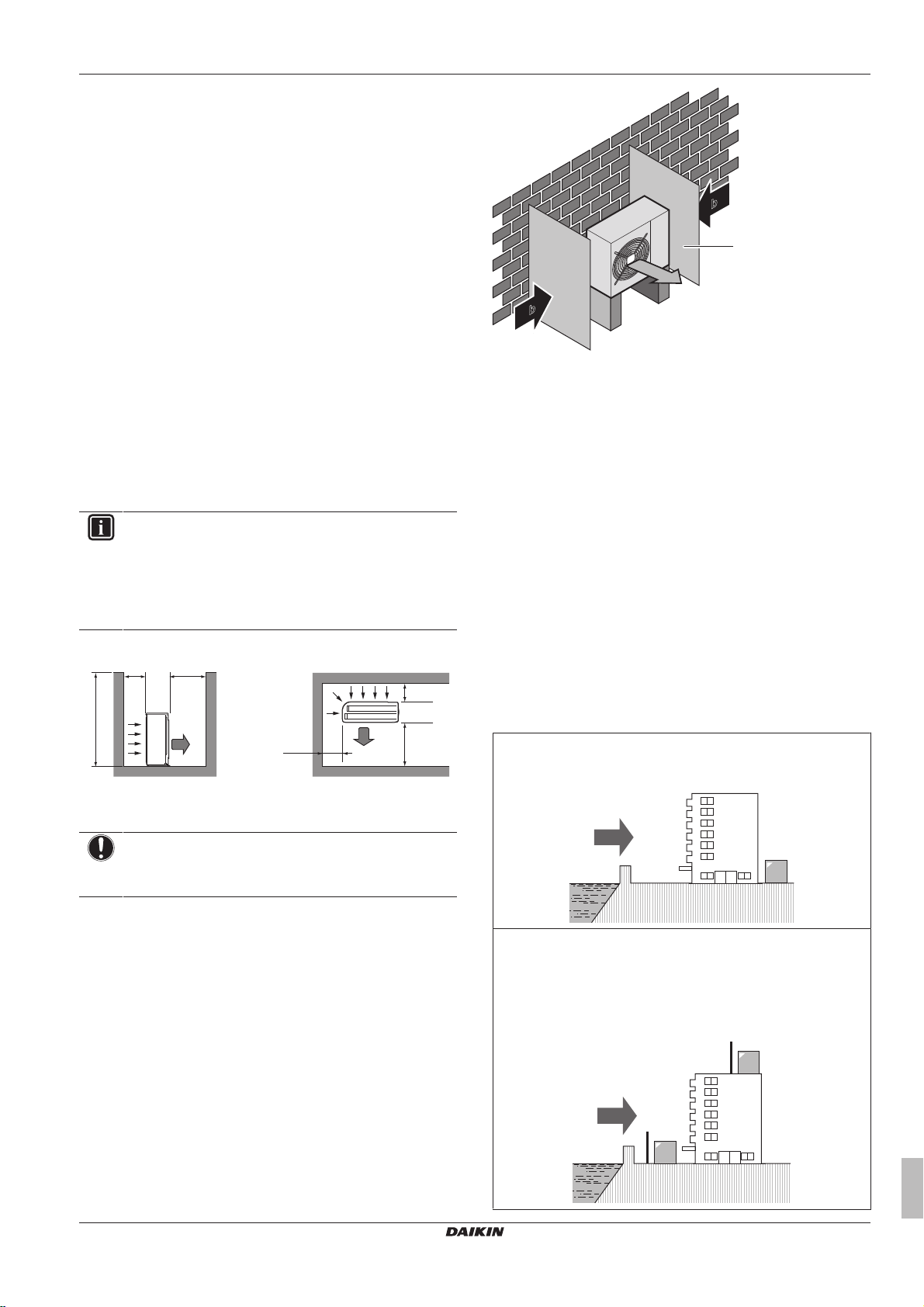
6 Preparation
≤1200
>250
>250
>250
>350
>350
(mm)(mm)
a
b
b
a
b
a
b
c
b
c
a
a
b
c
d
c
d
6.1 Overview: Preparation
This chapter describes what you have to do and know before going
on-site.
It contains information about:
▪ Preparing the installation site
▪ Preparing the refrigerant piping
▪ Preparing the water piping
▪ Preparing the electrical wiring
6 Preparation
6.2 Preparing installation site
Do NOT install the unit in places often used as work place. In case
of construction works (e.g. grinding works) where a lot of dust is
created, the unit must be covered.
Choose the installation location with sufficient place for carrying the
unit in and out of the site.
6.2.1 Installation site requirements of the outdoor unit
INFORMATION
Also read the following requirements:
▪ General installation site requirements. See the
"General safety precautions" chapter.
▪ Refrigerant piping requirements (length, height
difference). See further in this "Preparation" chapter.
Mind the following spacing guidelines:
a Baffle plate
b Prevailing wind direction
c Air outlet
Do NOT install the unit in the following places:
▪ Sound sensitive areas (e.g. near a bedroom), so that the
operation noise will cause no trouble.
Note: If the sound is measured under actual installation
conditions, the measured value might be higher than the sound
pressure level mentioned in Sound spectrum in the data book due
to environmental noise and sound reflections.
▪ In places where a mineral oil mist, spray or vapour may be
present in the atmosphere. Plastic parts may deteriorate and fall
off or cause water leakage.
It is NOT recommended to install the unit in the following places
because it may shorten the life of the unit:
▪ Where the voltage fluctuates a lot
▪ In vehicles or vessels
▪ Where acidic or alkaline vapour is present
Seaside installation. Make sure the outdoor unit is NOT directly
exposed to sea winds. This is to prevent corrosion caused by high
levels of salt in the air, which might shorten the life of the unit.
Install the outdoor unit away from direct sea winds.
Example: Behind the building.
a Air outlet
b Air inlet
NOTICE
▪ Do NOT stack the units on each other.
▪ Do NOT hang the unit on a ceiling.
Strong winds (≥18 km/h) blowing against the outdoor unit’s air outlet
causes short circuit (suction of discharge air). This may result in:
▪ deterioration of the operational capacity;
▪ frequent frost acceleration in heating operation;
▪ disruption of operation due to decrease of low pressure or
increase of high pressure;
▪ a broken fan (if a strong wind blows continuously on the fan, it
may start rotating very fast, until it breaks).
It is recommended to install a baffle plate when the air outlet is
exposed to wind.
It is recommended to install the outdoor unit with the air inlet facing
the wall and NOT directly exposed to the wind.
ERLQ004~008CA + EHVH04+08SU18+26CB6W
Daikin Altherma – Low temperature split
4P449978-1 – 2016.06
If the outdoor unit is exposed to direct sea winds, install a
windbreaker.
▪ Height of windbreaker≥1.5×height of outdoor unit
▪ Mind the service space requirements when installing the
windbreaker.
Installer reference guide
23
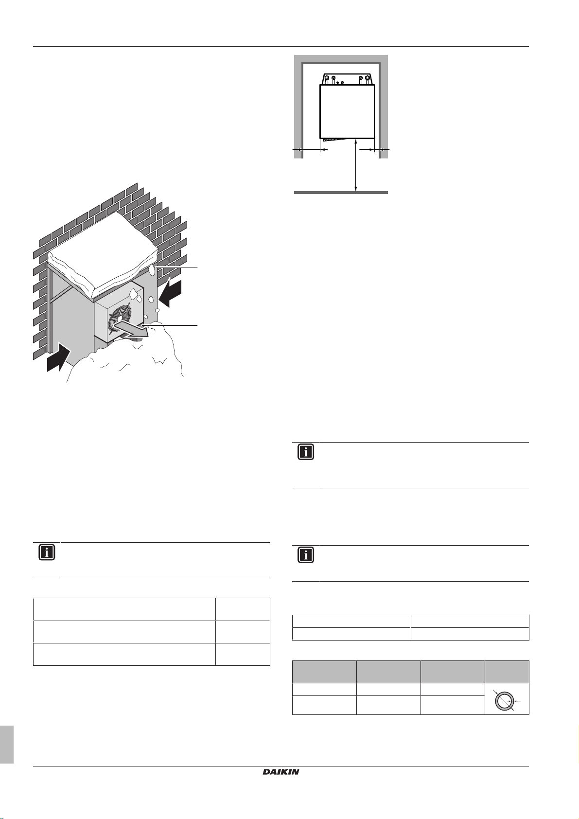
6 Preparation
a
b
c
c
d
>500
>10>150
(mm)
t
Ø
a Sea wind
b Building
c Outdoor unit
d Windbreaker
The outdoor unit is designed for outdoor installation only, and for
ambient temperatures ranging 10~43°C in cooling mode and –
25~25°C in heating mode.
6.2.2 Additional installation site requirements of the outdoor unit in cold climates
Protect the outdoor unit against direct snowfall and take care that the
outdoor unit is NEVER snowed up.
a Snow cover or shed
b Pedestal
c Prevailing wind direction
d Air outlet
▪ In any case, provide at least 300mm of free space below the unit.
Additionally, make sure the unit is positioned at least 100 mm
above the maximum expected level of snow. See "7.3 Mounting
the outdoor unit"on page30 for more details.
In heavy snowfall areas it is very important to select an installation
site where the snow will NOT affect the unit. If lateral snowfall is
possible, make sure that the heat exchanger coil is NOT affected by
the snow. If necessary, install a snow cover or shed and a pedestal.
6.2.3 Installation site requirements of the indoor unit
INFORMATION
Also read the precautions and requirements in the
"General safety precautions" chapter.
▪ Mind the following measurements guidelines:
Maximum refrigerant piping length between indoor
unit and outdoor unit
Minimum refrigerant piping length between indoor
unit and outdoor unit
Maximum height difference between indoor unit and
outdoor unit
▪ Mind the following spacing installation guidelines:
30m
3m
20m
Do NOT install the unit in places such as:
▪ In places where a mineral oil mist, spray or vapour may be
present in the atmosphere. Plastic parts may deteriorate and fall
off or cause water leakage.
▪ Sound sensitive areas (e.g. near a bedroom), so that the
operation noise will cause no trouble.
▪ The foundation must be strong enough to bear the weight of the
unit. Take the weight of the unit with a domestic hot water tank full
of water into account.
Make sure, in the event of a water leak, water cannot cause any
damage to the installation space and surroundings.
▪ In places with high humidity (max. RH=85%), for example a
bathroom.
▪ In places where frost is possible. Ambient temperature around the
indoor unit should be >5°C.
▪ The indoor unit is designed for indoor installation only and for
ambient temperatures ranging from 5~35°C.
6.2.4 Installation site requirements of the domestic hot water tank kit
INFORMATION
The domestic hot water tank kit is mounted into the indoor
unit. The use of tank kit EKVSU260A extends the height of
the indoor unit by 190mm.
6.3 Preparing refrigerant piping
6.3.1 Refrigerant piping requirements
INFORMATION
Also read the precautions and requirements in the
"General safety precautions" chapter.
▪ Piping material: Phosphoric acid deoxidised seamless copper.
▪ Piping diameter:
Liquid piping Ø6.4mm (1/4")
Gas piping Ø15.9mm (5/8")
▪ Piping temper grade and thickness:
Outer diameter
(Ø)
6.4mm (1/4") Annealed (O) ≥0.8mm
15.9mm (5/8") Annealed (O) ≥1.0mm
Temper grade Thickness (t)
(a)
Installer reference guide
24
(a) Depending on the applicable legislation and the unit's
maximum working pressure (see "PS High" on the unit
name plate), larger piping thickness might be required.
ERLQ004~008CA + EHVH04+08SU18+26CB6W
Daikin Altherma – Low temperature split
4P449978-1 – 2016.06
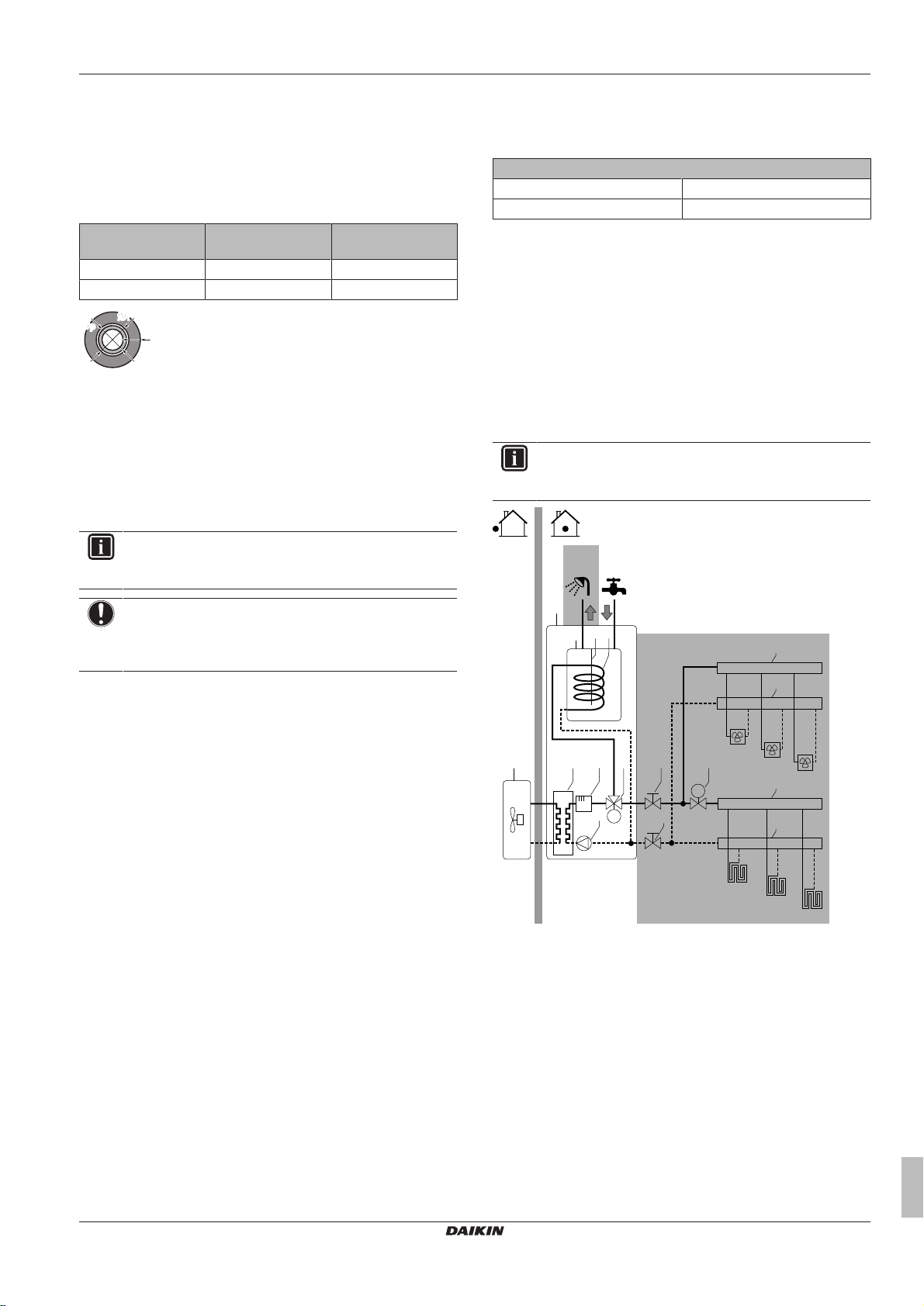
6 Preparation
ØiØ
i
t
ØpØ
p
M
M
FCU1
FCU2
FCU3
FHL1
FHL2
FHL3
a
b
c d
e f
g f h
i
i
i
i
j k
l
89°C
75°C
6.3.2 Refrigerant piping insulation
▪ Use polyethylene foam as insulation material:
▪ with a heat transfer rate between 0.041 and 0.052W/mK (0.035
and 0.045kcal/mh°C)
▪ with a heat resistance of at least 120°C
▪ Insulation thickness
Pipe outer diameter
(Øp)
Insulation inner
diameter (Øi)
Insulation thickness
(t)
6.4mm (1/4") 8~10mm 10mm
15.9mm (5/8") 16~20mm 13mm
If the temperature is higher than 30°C and the humidity is higher
than RH 80%, the thickness of the insulation materials should be at
least 20 mm to prevent condensation on the surface of the
insulation.
6.4 Preparing water piping
6.4.1 Water circuit requirements
INFORMATION
Also read the precautions and requirements in the
"General safety precautions" chapter.
▪ Water flow. You can find the minimum required water flow for
indoor unit operation in the following table. In all cases, this flow
needs to be guaranteed. When the flow is lower, the indoor unit
will stop operation and display error 7H.
Minimum required flow rate
04+08 models 12l/min
11+16 models 15l/min
▪ Field supply components – Water. Only use materials that are
compatible with water used in the system and with the materials
used in the indoor unit.
▪ Field supply components – Water pressure and temperature.
Check that all components in the field piping can withstand the
water pressure and water temperature.
▪ Water pressure. The maximum water pressure is 4 bar. Provide
adequate safeguards in the water circuit to ensure that the
maximum pressure is NOT exceeded.
▪ Water temperature. All installed piping and piping accessories
(valve, connections,…) MUST withstand the following
temperatures:
INFORMATION
The following illustration is an example and might NOT
match your system layout.
NOTICE
In case of plastic pipes, make sure they are fully oxygen
diffusion tight according to DIN 4726. The diffusion of
oxygen into the piping can lead to excessive corrosion.
▪ Connecting piping – Legislation. Make all piping connections in
accordance with the applicable legislation and the instructions in
the "Installation" chapter, respecting the water inlet and outlet.
▪ Connecting piping – Force. Do NOT use excessive force when
connecting the piping. Deformation of the piping can cause
malfunctioning of the unit.
▪ Connecting piping – Tools. Only use appropriate tooling to
handle brass, which is a soft material. If NOT, pipes will get
damaged.
▪ Connecting piping – Air, moisture, dust. If air, moisture or dust
gets into the circuit, problems may occur. To prevent this:
▪ Only use clean pipes
▪ Hold the pipe end downwards when removing burrs.
▪ Cover the pipe end when inserting it through a wall, to prevent
dust and/or particles entering the pipe.
▪ Use a decent thread sealant to seal connections.
▪ Closed circuit. Use the indoor unit ONLY in a closed water
system. Using the system in an open water system will lead to
excessive corrosion.
▪ Glycol. For safety reasons, it is NOT allowed to add any kind of
glycol to the water circuit.
▪ Piping length. It is recommended to avoid long runs of piping
between the domestic hot water tank and the hot water end point
(shower, bath,…) and to avoid dead ends.
▪ Piping diameter. Select the water piping diameter in relation to
the required water flow and the available external static pressure
of the pump. See "14 Technical data"on page86 for the external
static pressure curves of the indoor unit.
▪ Drainage – Low points. Provide drain taps at all low points of the
system in order to allow complete drainage of the water circuit.
▪ Drainage – Pressure relief valves. Provide a proper drain for the
pressure relief valves (of both the domestic hot water tank and the
domestic hot water tank kit) to avoid water dripping out of the unit.
For the discharge piping connected to these valves, respect the
a Outdoor unit
b Indoor unit
c Heat exchanger
d Backup heater
e Pump
f Stop valve
g Motorised 3-way valve
h Motorised 2-way valve (field supply)
i Collector
j Domestic hot water tank
k Heat exchanger coil
l Booster heater
FCU1...3 Fan coil unit (optional) (field supply)
FHL1...3 Floor heating loop (field supply)
ERLQ004~008CA + EHVH04+08SU18+26CB6W
Daikin Altherma – Low temperature split
4P449978-1 – 2016.06
Installer reference guide
25
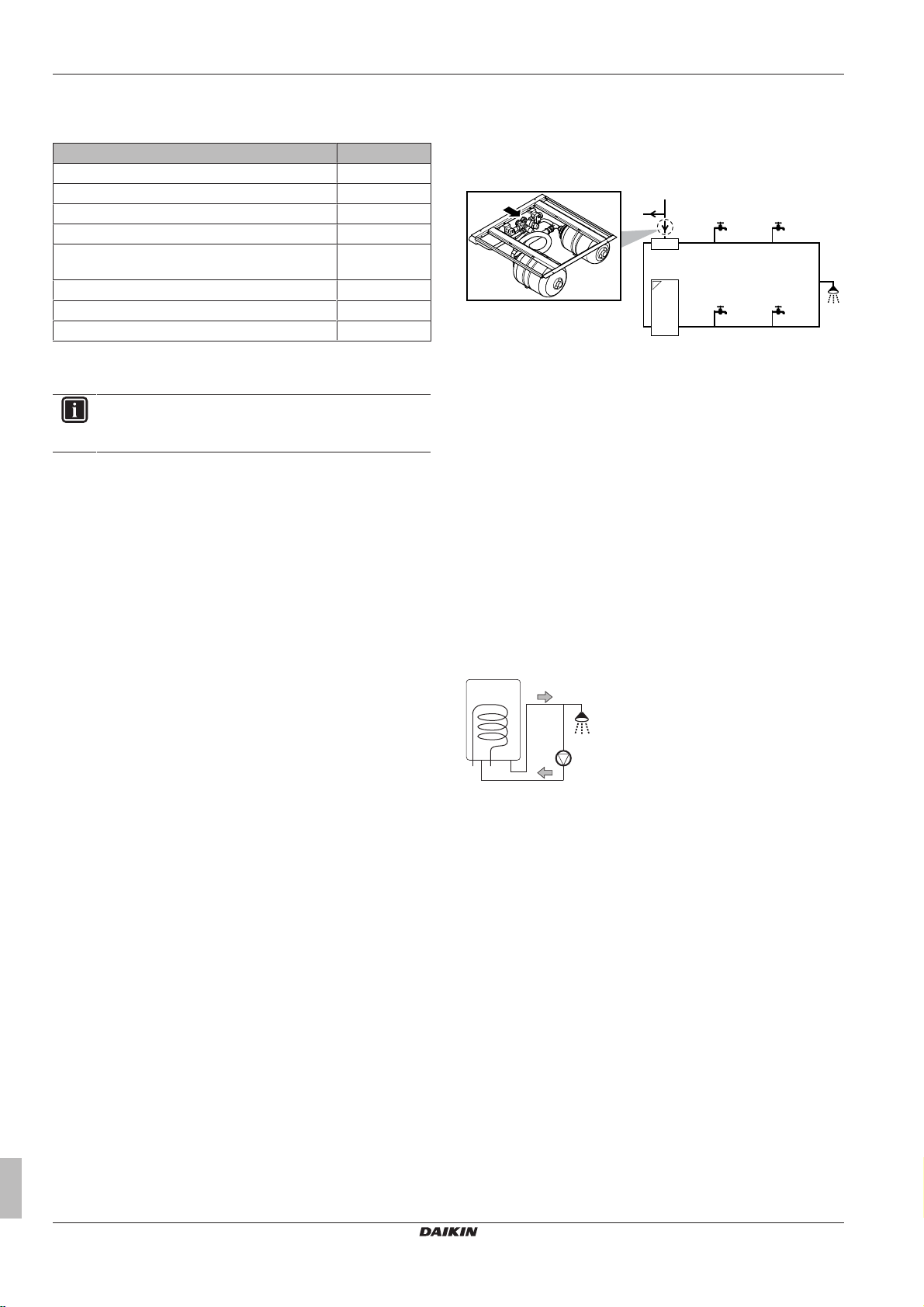
6 Preparation
a
b
e
c
d
e
h
f f
g g
e
c
d
a b
requirements from the table below. For more information, see
"7.8.4 To connect the water piping" on page 39 and "7.8.5 To
connect the pressure relief valve to the drain"on page41.
Item Requirement
Pressure relief valve diameter 15mm
Discharge pipe diameter (to pressure relief valve) 15mm
Discharge piping diameter (from tundish) 22mm
Discharge piping material (from tundish) Metal
Vertical length below tundish, before first elbow or
bend
Continuous fall after first elbow or bend ≥1:200
Maximum resistance
(a)
Resistance created by each elbow or bend 0.8m
(a) The maximum allowed resistance (i.e. equivalent length) is
expressed as a length of straight pipe (i.e. no elbows or
bends).
INFORMATION
All piping MUST be installed according to section G3 of the
Building Regulations.
▪ Air vents. Provide air vents at all high points of the system, which
must also be easily accessible for servicing. An automatic air
purge is provided in the indoor unit. Check that the air purge is
NOT tightened too much, so that automatic release of air in the
water circuit is possible.
▪ Zn-coated parts. Never use Zn-coated parts in the water circuit.
Because the unit's internal water circuit uses copper piping,
excessive corrosion may occur.
▪ Non-brass metallic piping. When using non-brass metallic
piping, insulate the brass and non-brass properly so that they do
NOT make contact with each other. This to prevent galvanic
corrosion.
▪ Valve – Separating circuits. When using a 3-way valve in the
water circuit make sure that the domestic hot water circuit and the
floor heating circuit is fully separated.
▪ Valve – Change‑over time. When using a 2-way valve or a 3-way
valve in the water circuit, the maximum change-over time of the
valve must be 60seconds.
▪ Filter. It is strongly recommended to install an additional filter on
the heating water circuit. Especially to remove metallic particles
from foul heating piping, it is recommended to use a magnetic or
cyclone filter, which can remove small particles. Small particles
may damage the unit and will NOT be removed by the standard
filter of the heat pump system.
▪ Domestic hot water tank – Capacity. To avoid stagnation of
water, it is important that the storage capacity of the domestic hot
water tank meets the daily consumption of domestic hot water.
▪ Domestic hot water tank – After installation. Immediately after
installation, the domestic hot water tank must be flushed with fresh
water. This procedure must be repeated at least once a day the
first 5 consecutive days after installation.
▪ Domestic hot water tank – Standstills. In cases where during
longer periods of time there is no consumption of hot water, the
equipment MUST be flushed with fresh water before usage.
▪ Domestic hot water tank – Disinfection. For the disinfection
function of the domestic hot water tank, see "8.3.2Domestic hot
water control: advanced"on page61.
▪ Domestic hot water tank kit – Clean pipes. Before installing the
domestic hot water tank kit, all piping and fittings must be flushed
free of flux and debris. Failure to do this may cause irreparable
damage to the tank kit control valves. Flush the system by
opening the hot water tap.
Installer reference guide
26
≥300mm
≤9m
▪ Domestic hot water tank kit – Pressure balancing. To prevent
large pressure differences at the taps and damage to the shower
valve due to high‑pressure cold water (5bar), provide a dedicated
2‑bar feed to both cold water and hot water taps. To do this, also
connect the cold water supply for the cold water taps to the
pressure reducing valve of the domestic hot water tank kit.
a Cold water supply into house at 5bar
b To 5-bar taps
c Pressure reducing valve (part of the domestic hot water
tank kit)
d Indoor unit
e Dedicated 2‑bar feed
f Cold water taps
g Hot water taps
▪ Domestic hot water tank kit – Secondary return. Where the
secondary return circuits are used, an additional expansion vessel
may be required.
▪ Thermostatic mixing valves. In accordance with the applicable
legislation, it may be necessary to install thermostatic mixing
valves.
▪ Hygienic measures. The installation must be in compliance with
the applicable legislation and may require additional hygienic
installation measures.
▪ Recirculation pump. In accordance with the applicable
legislation, it may be required to connect a recirculation pump in
between the hot water end point and the recirculation connection
of the domestic hot water tank.
a Recirculation connection
b Hot water connection
c Shower
d Recirculation pump
6.4.2 Formula to calculate the expansion vessel pre-pressure
The pre-pressure (Pg) of the vessel depends on the installation
height difference (H):
Pg=0.3+(H/10) (bar)
6.4.3 To check the water volume and flow rate
The indoor unit has an expansion vessel of 10litre with a factory-set
pre-pressure of 1bar.
To make sure that the unit operates properly:
▪ You must check the minimum and maximum water volume.
▪ You might need to adjust the pre-pressure of the expansion
vessel.
Minimum water volume
Check that the total water volume in the installation is minimum
10litre, the internal water volume of the indoor unit NOT included.
ERLQ004~008CA + EHVH04+08SU18+26CB6W
Daikin Altherma – Low temperature split
4P449978-1 – 2016.06
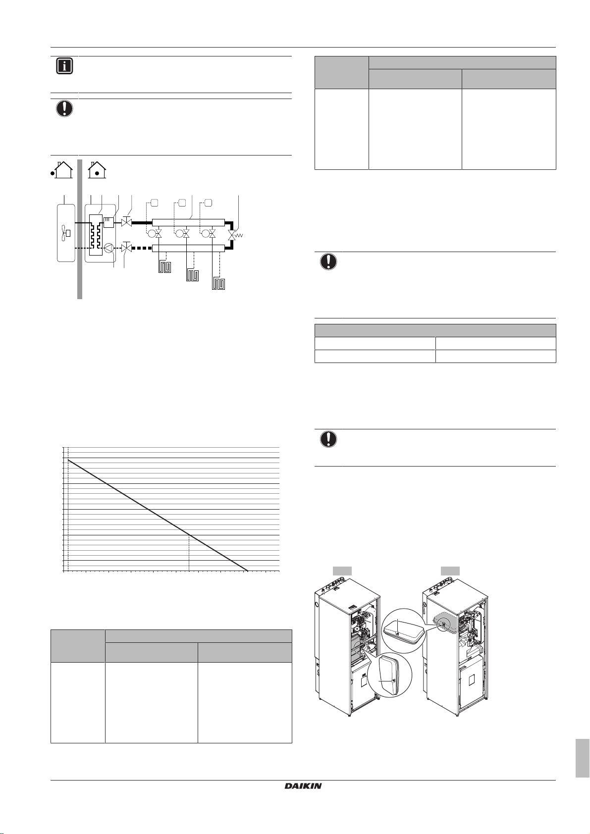
6 Preparation
FHL1
FHL2
FHL3
M1
T1
M2T2M3
T3
fdcba
f
g h
e
0.3
0.5
1
1.5
2
2.5
100500
10
150 200 250 300 350 400 450
a
b
180 l
260 l
a
a
INFORMATION
In critical processes, or in rooms with a high heat load,
extra water might be required.
NOTICE
When circulation in each space heating loop is controlled
by remotely controlled valves, it is important that the
minimum water volume is guaranteed, even if all of the
valves are closed.
a Outdoor unit
b Indoor unit
c Heat exchanger
d Backup heater
e Pump
f Shut-off valve
g Collector (field supply)
h By-pass valve (field supply)
FHL1...3 Floor heating loop (field supply)
T1...3 Individual room thermostat (optional)
M1...3 Individual motorised valve to control loop FHL1...3 (field
supply)
Maximum water volume
Use the following graph to determine the maximum water volume for
the calculated pre-pressure.
Installation
height
difference
(a)
≤280l >280l
>7m Do the following:
▪ Increase the pre-
pressure.
▪ Check if the water
volume does NOT
exceed the maximum
Water volume
The expansion vessel of
the indoor unit is too
small for the installation.
In this case, it is
recommended to install
an extra vessel outside
the unit.
allowed water volume.
(a) This is the height difference (m) between the highest point
of the water circuit and the indoor unit. If the indoor unit is
at the highest point of the installation, the installation height
is 0m.
Minimum flow rate
Check that the minimum flow rate (required during defrost/backup
heater operation) in the installation is guaranteed in all conditions.
NOTICE
When circulation in each or certain space heating loops is
controlled by remotely controlled valves, it is important that
the minimum flow rate is guaranteed, even if all valves are
closed. In case the minimum flow rate cannot be reached,
a flow error 7H will be generated (no heating/operation).
Minimum required flow rate
04+08 models 12l/min
11+16 models 15l/min
See the recommended procedure as described in "9.4 Checklist
during commissioning"on page74.
6.4.4 Changing the pre-pressure of the expansion vessel
NOTICE
Only a licensed installer may adjust the pre-pressure of the
expansion vessel.
When changing the default pre-pressure of the expansion vessel
(1bar) is required, take following guidelines into account:
▪ Only use dry nitrogen to set the expansion vessel pre-pressure.
▪ Inappropriate setting of the expansion vessel pre-pressure will
lead to malfunction of the system.
Changing the pre-pressure of the expansion vessel should be done
by releasing or increasing nitrogen pressure through the Schrader
valve of the expansion vessel.
a Pre-pressure (bar)
b Maximum water volume (l)
Example: Maximum water volume and expansion vessel prepressure
Installation
height
difference
(a)
≤280l >280l
≤7m No pre-pressure
adjustment is required.
Water volume
Do the following:
▪ Decrease the pre-
pressure.
▪ Check if the water
ERLQ004~008CA + EHVH04+08SU18+26CB6W
Daikin Altherma – Low temperature split
4P449978-1 – 2016.06
volume does NOT
exceed the maximum
allowed water volume.
a Schrader valve
Installer reference guide
27
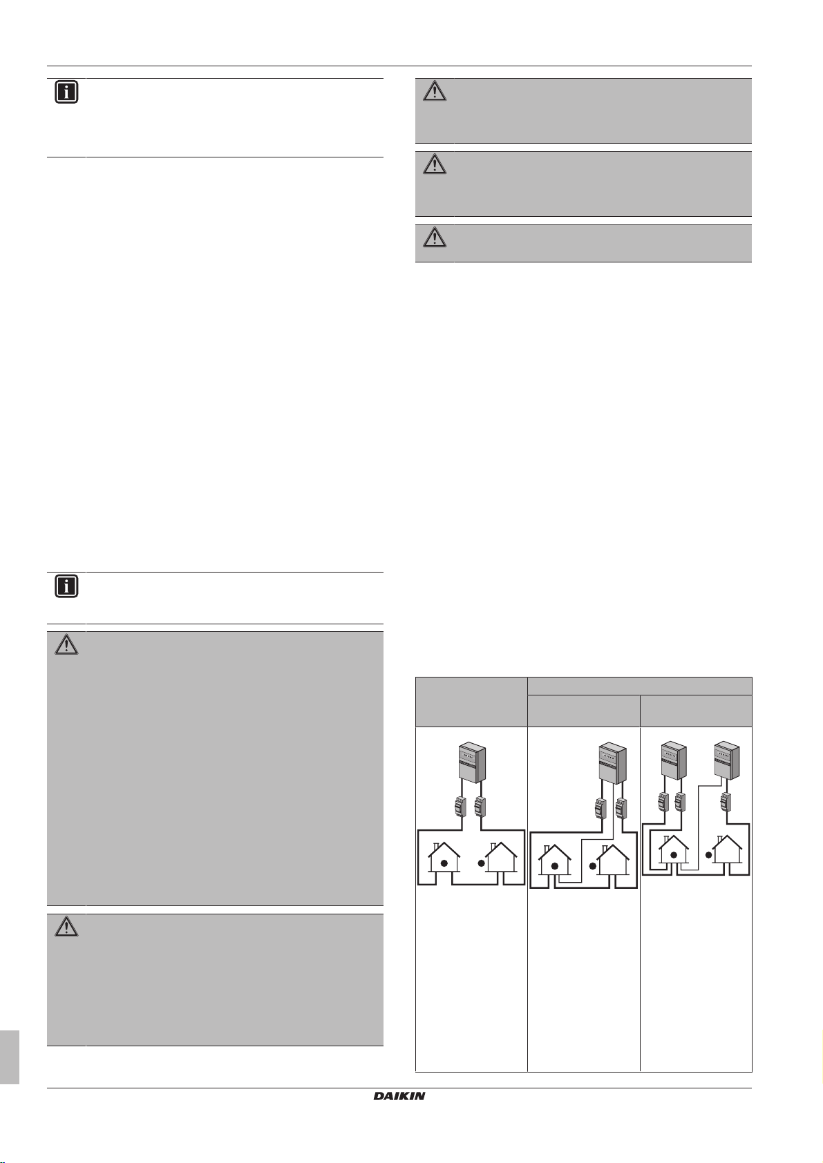
6 Preparation
1
5
8
0
1
5
0
0
0
2
a
3
1
4
5
8
0
1
5
0
0
0
2
b
3
5 3
a
b
14
5
8
0
1
5
0
0
0
5
8
0
1
5
0
0
0
2
INFORMATION
Domestic hot water tank kit (EKVSU180+260A). The
domestic hot water kit also contains 2 expansion vessels.
Check that they are pressurised by pushing their Schrader
valves (purging air).
6.4.5 To check the water volume: Examples
Example 1
The indoor unit is installed 5 m below the highest point in the water
circuit. The total water volume in the water circuit is 100l.
No actions or adjustments are required.
Example 2
The indoor unit is installed at the highest point in the water circuit.
The total water volume in the water circuit is 350l.
Actions:
▪ Because the total water volume (350 l) is more than the default
water volume (280l), the pre-pressure must be decreased.
▪ The required pre-pressure is:
Pg = (0.3+(H/10))bar = (0.3+(0/10))bar=0.3bar.
▪ The corresponding maximum water volume at 0.3 bar is 410 l.
(See the graph in the chapter above).
▪ Because 350 l is lower than 410 l, the expansion vessel is
appropriate for the installation.
6.5 Preparing electrical wiring
6.5.1 About preparing electrical wiring
INFORMATION
Also read the precautions and requirements in the
"General safety precautions" chapter.
WARNING
The backup heater MUST have a dedicated power supply
and MUST be protected by the safety devices required by
the applicable legislation.
WARNING
The booster heater MUST have a dedicated power supply
and MUST be protected by the safety devices required by
the applicable legislation.
WARNING
ALWAYS use multicore cable for power supply cables.
6.5.2 About preferential kWh rate power supply
Electricity companies throughout the world work hard to provide
reliable electric service at competitive prices and are often
authorized to bill clients at benefit rates. E.g. time-of-use rates,
seasonal rates, Wärmepumpentarif in Germany and Austria, ...
This equipment allows for connection to such preferential kWh rate
power supply delivery systems.
Consult with the electricity company acting as provider at the site
where this equipment is to be installed to know whether it is
appropriate to connect the equipment in one of the preferential kWh
rate power supply delivery systems available, if any.
When the equipment is connected to such preferential kWh rate
power supply, the electricity company is allowed to:
▪ interrupt power supply to the equipment for certain periods of time;
▪ demand that the equipment only consumes a limited amount of
electricity during certain periods of time.
The indoor unit is designed to receive an input signal by which the
unit switches into forced off mode. At that moment, the outdoor unit
compressor will not operate.
Whether the power supply is interrupted or not, the wiring to the unit
is different.
WARNING
▪ If the power supply has a missing or wrong N-phase,
6.5.3 Overview of electrical connections except external actuators
equipment might break down.
▪ Establish proper earthing. Do NOT earth the unit to a
utility pipe, surge absorber, or telephone earth.
Incomplete earthing may cause electrical shock.
Normal power
supply
Preferential kWh rate power supply
Power supply is
NOT interrupted
Power supply is
interrupted
▪ Install the required fuses or circuit breakers.
▪ Secure the electrical wiring with cable ties so that the
cables do NOT come in contact with sharp edges or
piping, particularly on the high-pressure side.
▪ Do NOT use taped wires, stranded conductor wires,
extension cords, or connections from a star system.
They can cause overheating, electrical shock or fire.
▪ Do NOT install a phase advancing capacitor, because
this unit is equipped with an inverter. A phase
advancing capacitor will reduce performance and may
cause accidents.
WARNING
▪ All wiring must be performed by an authorized
electrician and must comply with the applicable
legislation.
▪ Make electrical connections to the fixed wiring.
▪ All components procured on the site and all electrical
construction must comply with the applicable
legislation.
During preferential
kWh rate power
supply activation,
power supply is NOT
interrupted. The
outdoor unit is turned
off by the control.
Remark: The
electricity company
must always allow the
power consumption
of the indoor unit.
During preferential
kWh rate power
supply activation,
power supply is
interrupted
immediately or after
some time by the
electricity company.
In this case, the
indoor unit must be
powered by a
separate normal
power supply.
Installer reference guide
28
ERLQ004~008CA + EHVH04+08SU18+26CB6W
Daikin Altherma – Low temperature split
4P449978-1 – 2016.06
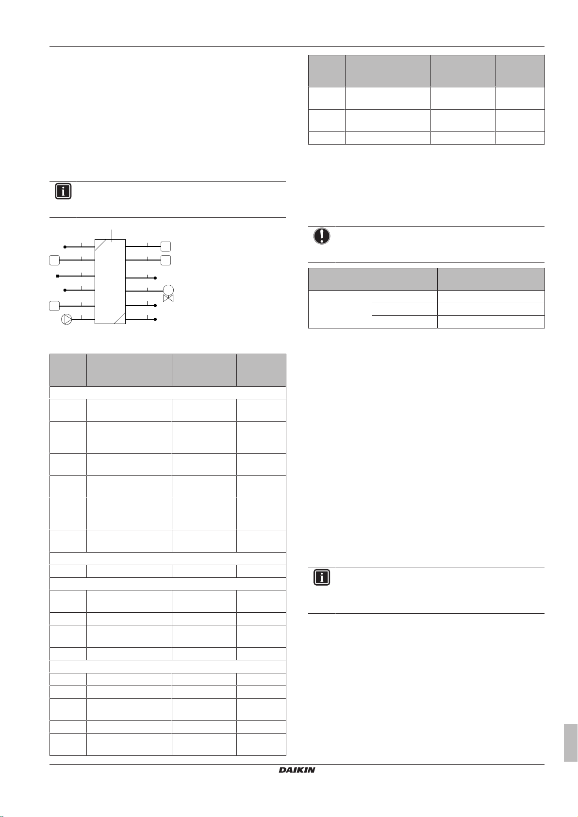
7 Installation
M
a
16
21
22
19
15
20
23
12
6
13
17
18
a Normal power supply
b Preferential kWh rate power supply
1 Power supply for outdoor unit
2 Power supply and interconnection cable to indoor unit
3 Power supply for backup heater
4 Preferential kWh rate power supply (voltage free contact)
5 Normal kWh rate power supply (to power the indoor unit
PCB in the event of power supply interruption of the
preferential kWh rate power supply)
6.5.4 Overview of electrical connections for external and internal actuators
The following illustration shows the required field wiring.
INFORMATION
The following illustration is an example and might NOT
match your system layout.
Item Description Wires Maximum
running
current
21 Space heating
2
(b)
operation control
22 Power consumption
digital inputs
23 Safety thermostat 2
(a) Refer to name plate on outdoor unit.
(b) Minimum cable section 0.75mm².
(c) Cable section 2.5mm².
(d) Cable section 0.75mm² till 1.25mm²; maximum length:
50m. Voltage-free contact shall ensure the minimum
applicable load of 15VDC, 10mA.
(e) Cable section 0.75mm² till 1.25mm²; maximum length:
500m. Applicable for both single user interface and dual
user interface connection.
2 (per input
signal)
(b)
(d)
NOTICE
More technical specifications of the different connections
are indicated on the inside of the indoor unit.
Backup heater
type
Power supply Required number of
conductors
*6W 1× 230V 2+GND + 2 bridges
3× 230V 3+GND + 1 bridge
3× 400V 4+GND
a Indoor unit
Item Description Wires Maximum
Outdoor unit and indoor unit power supply
1 Power supply for
outdoor unit
2 Power supply and
2+GND or
3+GND
3
interconnection cable to
indoor unit
3 Power supply for
See table below. —
backup heater
3a Power supply for
2+GND
booster heater
4 Preferential kWh rate
2
power supply (voltage
free contact)
5 Normal kWh rate power
2 6.3A
supply
User interface
6 User interface 2
Optional equipment
11 Power supply for
2
bottom plate heater
12 Room thermostat 3 or 4 100mA
13 Outdoor ambient
2
temperature sensor
15 Heat pump convector 4 100mA
Field supplied components
16 Shut-off valve 2 100mA
17 Electricity meter 2 (per meter)
18 Domestic hot water
pump
19 Alarm output 2
20 Changeover to external
ERLQ004~008CA + EHVH04+08SU18+26CB6W
Daikin Altherma – Low temperature split
4P449978-1 – 2016.06
heat source control
2
2
running
current
(a)
(c)
(c)
(d)
(e)
(b)
(b)
(b)
(b)
(b)
(b)
7 Installation
7.1 Overview: Installation
This chapter describes what you have to do and know on-site to
install the system.
Typical workflow
Installation typically consists of the following stages:
1 Mounting the outdoor unit.
2 Mounting the indoor unit.
3 Connecting the refrigerant piping.
4 Checking the refrigerant piping.
5 Charging refrigerant.
6 Connecting the water piping (including the installation of the
domestic hot water tank kit).
7 Connecting the electrical wiring.
8 Finishing the outdoor installation.
9 Finishing the indoor installation.
INFORMATION
Depending on the units and/or the installation conditions, it
might be necessary to connect electrical wiring before you
(b)
(b)
(b)
can charge refrigerant.
7.2 Opening the units
7.2.1 About opening the units
At certain times, you have to open the unit. Example:
▪ When connecting the refrigerant piping
▪ When connecting the electrical wiring
▪ When maintaining or servicing the unit
Installer reference guide
29
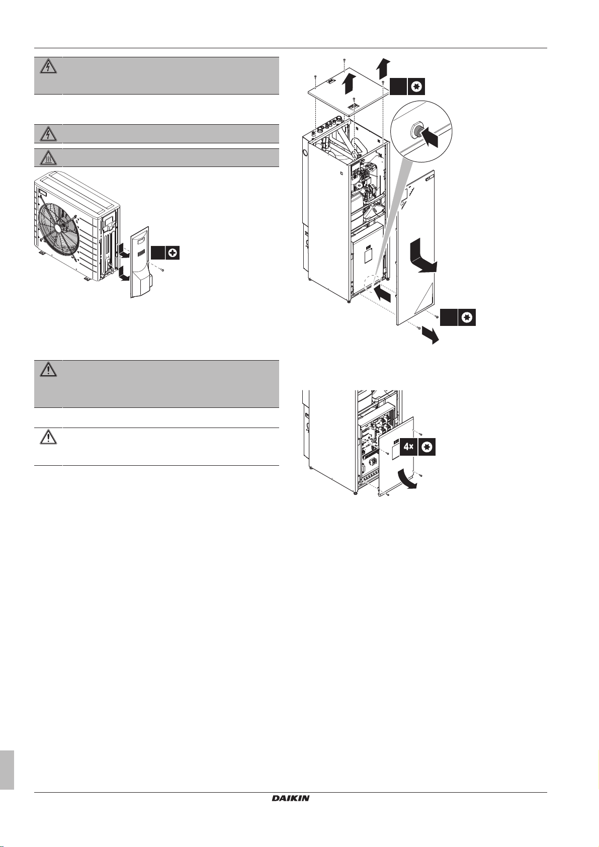
7 Installation
1×
1
2
2
2
3
4
5
1
2
4×
2×
4×
DANGER: RISK OF ELECTROCUTION
Do NOT leave the unit unattended when the service cover
is removed.
7.2.2 To open the outdoor unit
DANGER: RISK OF ELECTROCUTION
DANGER: RISK OF BURNING
7.2.3 To open the indoor unit
1 Loosen and remove the screws at the bottom of the unit.
2 Push on the button at the bottom of the front plate.
WARNING: Sharp edges
Take the front plate on the upper part instead of the lower
part. Watch your fingers, there are sharp edges on the
lower part of the front plate.
3 Slide the front panel of the unit downwards and remove it.
CAUTION
The front panel is heavy. Be careful NOT to jam your
fingers when opening or closing the unit.
4 Loosen and remove the 4 screws that fix the top panel.
5 Remove the top panel from the unit.
7.2.4 To open the switch box cover of the indoor unit
7.3 Mounting the outdoor unit
7.3.1 About mounting the outdoor unit
When
You have to mount the outdoor and indoor unit before you can
connect the refrigerant and water piping.
Typical workflow
Mounting the outdoor unit typically consists of the following stages:
1 Providing the installation structure.
2 Installing the outdoor unit.
3 Providing drainage.
4 Preventing the outdoor unit from falling over.
5 Protecting the unit against snow and wind by installing a snow
cover and baffle plates. See "Preparing installation site" in
"6Preparation"on page23.
Installer reference guide
30
ERLQ004~008CA + EHVH04+08SU18+26CB6W
Daikin Altherma – Low temperature split
4P449978-1 – 2016.06
 Loading...