

Page 1
EHOBG12ABV1
EHOBG18ABV1
Daikin Europe NV
Installation instructions
Installationsanleitung
Instructions d'installation
Installatievoorschrift
Istruzioni d'installazione
Instrukcje instalacji
English
Deutsch
Français
Nederlands
Italiano
Polski
Page 2

TABLE OF CONTENTS
1 Safety instructions 5
2 Unit description 6
2.1 General ............................................................................................................................................................................................ 6
2.2 Functioning ...................................................................................................................................................................................... 6
2.3 Operating modes ............................................................................................................................................................................. 6
2.4 PC Interface .................................................................................................................................................................................... 8
2.5 Test programs ................................................................................................................................................................................. 8
3 Main components 9
3.1 Accessories ................................................................................................................................................................................... 10
4 Installation 11
4.1 Installation measurements ............................................................................................................................................................ 11
4.2 Installation space ........................................................................................................................................................................... 13
4.3 Assembly ....................................................................................................................................................................................... 14
5 Connecting 16
5.1 Connecting CH installation ............................................................................................................................................................ 16
5.2 Connecting electronically .............................................................................................................................................................. 18
5.3 Connect room thermostat .............................................................................................................................................................. 19
5.4 Connecting gas ............................................................................................................................................................................. 20
5.5 Flue and air supply duct ................................................................................................................................................................ 21
5.6 Outlet systems ............................................................................................................................................................................... 22
5.7 Flue material .................................................................................................................................................................................. 23
5.8 Connection to a flue system without air inlet (B23, B33) .............................................................................................................. 25
5.9 Connection to a sealed flue system. ............................................................................................................................................. 26
6 Commissioning the unit and the Installation 34
6.1 Filling and air purge of unit and installation ................................................................................................................................... 34
6.2 Commissioning the unit ................................................................................................................................................................. 35
6.3 Switching off the unit ..................................................................................................................................................................... 36
7 Setting and adjustment 37
7.1 Direct via operating panel .............................................................................................................................................................. 37
7.2 Parameter settings via the service code ....................................................................................................................................... 38
7.3 Setting maximum CH power .......................................................................................................................................................... 40
7.4 Setting pump setting ...................................................................................................................................................................... 40
7.5 Weather dependent regulation ...................................................................................................................................................... 40
7.6 Conversion to different type of gas................................................................................................................................................ 41
7.7 Gas/air regulation .......................................................................................................................................................................... 41
7.8 Setting gas/air regulation ............................................................................................................................................................... 42
8 Malfunctions 44
8.1 Show last malfunction ................................................................................................................................................................... 44
8.2 Malfunction codes ......................................................................................................................................................................... 44
8.3 Other faults .................................................................................................................................................................................... 45
9 Maintenance 48
10 Technical specifications 50
10.1 NTC resistances ............................................................................................................................................................................ 50
10.2 Technical Product Fiche in accordance to CELEX-32013R0811 .................................................................................................. 51
10.3 Electrical diagram .......................................................................................................................................................................... 52
11 Warranty conditions 53
© 2019 Daikin Europe NV
All rights reserved.
The information provided applies to the product in its standard version. Daikin Europe NV can therefore not be held liable for any damages arising from any
specifications of the product which deviate from the standard version. The available information has been compiled with the greatest possible care, but Daikin Europe
NV can not be held liable for any mistakes in the information, or for any consequences thereof. Daikin Europe NV cannot be held liable for any damage arising from
work carried out by third parties.
Subject to change.
Daikin Europe NV 3
Page 3
These installation instructions
With these installation instructions, you can safely assemble, install and maintain the
unit. Carefully follow the instructions.
In case of any doubt, please contact the manufacturer.
Keep the installation instructions near the unit.
Abbreviations and terms used
Description To be referred to as
Daikin EHOBG12ABV1, EHOBG18ABV1 Unit
Unit with piping for central heating CH installation
System with pipes for domestic hot water DHW installation
Symbols
The following symbols are used in this manual:
CAUTION
Procedures which - if they are not carried out with the
necessary care - may cause damage to the product, the
surroundings, the environment or injury.
IMPORTANT
Procedures and/or instructions which, if they are not
followed, will have a negative effect on the functioning of the
unit.
Daikin Europe NV
4
Page 4
Service and technical support for the installer
For information about specific settings, installation, maintenance and repair work, as an
installer, please contact your local Daikin dealer.
Identification of the product
You will find the unit details on the type plate on the bottom of the unit.
The data plate contains, beside the supplier information and the boiler specification (boiler
type and model name) the following information:
******-yymm****** Product code-Serial No.
YY= year of production, mm = month of production
PIN Product Identification Number
Data related to Central Heating
Information regarding electrical power supply
Voltage, mains frequency, elmax, IP-class)
PMS Permissible overpressure in CH circuit in bar
Qn HS Input related to gross caloric value in kilowatts
Qn Hi Input related to net caloric value in kilowatts
Pn Output in kilowatts
BE, DE, FR, IT, PL Countries of Destination (EN 437)
I2E(s), I2H, IIELL3P,
II2H3P,
II2Esi3P
G20-20 mbar
G25-25 mbar
B23, …. C93(x) Approved flue gas category (EN 15502)
Tmax Max. flow temperature in °C
IPX4D Electrical protection class
Approved unit categories (EN 437)
Gas group and gas connection pressure as set at the factory
(EN 437)
1 SAFETY INSTRUCTIONS
The manufacturer Daikin Europe NV accepts no liability for damage or injury caused by the
failure to (strictly) observe the safety instructions, or negligence during the installation of the
Daikin EHOBG*ABV1 wall-mounted gas boiler and any associated accessories.
This device is not intended for use by people (including children) with reduced physical,
sensory or mental abilities, or lack of experience and knowledge, unless they are given
supervision or instructions on the use of the device by a person who is responsible for their
safety.
The entire installation must meet the applicable local technical and (safety) instructions, for the
gas installation, the electrical installation, smoke extraction installation, drinking water
installation, and central heating installation.
IMPORTANT
This product is intended for domestic use only.
Daikin Europe NV
5
Page 5
2 UNIT DESCRIPTION
2.1 General
The Daikin EHOBG*ABV1 wall-mounted gas boiler is a closed unit. The unit is intended
to provide heat to the water of a CH-installation and the domestic hot water installation.
The air supply and combustible gas outlet can be connected to the unit by means of
two separate pipes. A concentric connection can be supplied upon demand. The unit
was tested in combination with the combi feedthrough, but the unit may also be
connected to combi feedthroughs which meet the universal test standards for combi
feedthroughs.
The unit can be connected to an assembly bracket if required, a frame with top
connection, and various installation sets. These are provided separately.
The Daikin EHOBG*ABV1 wall-mounted gas boilers have the CE marking and electrical
protection class IP44.
The unit is delivered for natural gas (G20) as a standard. On request, the unit can also
be provided for propane (G31).
2.2 Functioning
The Daikin EHOBG*ABV1 wall-mounted gas boiler is a modulating high-efficiency
boiler. This means that the power is modulated to suit the required heat demand.
A copper CH circuit is integrated in the aluminum heat exchanger.
The water of the DHW installation can be heated by connecting the unit to an indirectly
heated tank using a three-way valve and tank sensor (see par.5.1 and 5.2). The built in
tank regulation of the unit ensures the domestic hot water provision takes precedence
over the heating. Both cannot work at the same time.
The unit is fitted with an electronic boiler controller, which operates the fan at every
heat requirement of the heating or the warm water supply, opens the gas valve, ignites
the boiler controller, and continuously monitors and regulates the flame, depending on
the requested power.
2.3 Operating modes
The operating mode of the unit is indicated by means of a code on the service display
of the operating panel.
-
Off
The unit is not in operation, but is connected to the electricity supply. No response is
given to requests for domestic hot water or CH water. The unit frost protection is active.
This means that the pump will start running and the exchanger will be heated up if the
temperature of the water in the system drops too far.
If the frost protection intervenes, the code
The pressure in the CH installation can also be read from the temperature display in
this operating mode (in bar).
Standby
The LED at the key is lit and possibly one of the LEDs of the tap comfort function.
The unit is ready to respond to a request for CH or tap water.
0
Post-running CH
After the end of the CH-operation, the pump will run for a specified time. The postpumping time is set to the value in par. 7.2 in its factory settings. This setting can be
changed. In addition to this, the pump will run automatically 1 time per 24 hours, for 10
seconds, in order to prevent it from getting stuck. This automatic switching on of the
pump takes place at the time of the last heating request. In order to change this, the
room thermostat needs to be set higher for a moment, at the required time of day.
7
will be displayed (heating up exchanger).
1
Requested temperature reached
The boiler controller may temporarily block the heat request. The boiler controller will
then be stopped. The block occurs because the required temperature has been
reached. When the temperature has sufficiently decreased, the block will be lifted.
2
Selftest
Once every 24 hours, the boiler controller tests the connected sensors. During the test,
the relay will not carry out any other tasks.
3
Ventilating
When the unit is started, the fan is first brought up to its correct start rpm. When the
start rpm is reached, the boiler controller will be ignited. Code 3 is also visible when
there is post-fanning after the boiler controller is stopped.
Daikin Europe NV
6
Page 6

4
Igniting
When the fan has reached the start rpm, the burner relay will be ignited by means of
electrical sparks. During the ignition, code
not ignite, a new attempt will be made after approximately 15 seconds. If after 4 ignition
attempts, the boiler controller has still not been ignited, the controller will go into downtime.
5
CH operation
An on/off thermostat, an OpenTherm thermostat, an outdoor sensor or a combination
thereof can be connected to the controller (see par. 10.3)
When there is a heat request from a thermostat, after the fan has started running (code
3
), the ignition will take place (code
During CH operation, the rpm of the fan and therefore the power of the unit can be
adjusted so the temperature of the CH water to the required CH supply temperature can
be controlled. If an on/off thermostat has been connected, this will be the CH supply
temperature set on the display. In case of an OpenTherm thermostat, the required CH
supply temperature is determined by the thermostat. In case of an outdoor sensor, the
required CH supply temperature is determined by the fuel line programmed in the boiler
controller. For the last two situations, the temperature set on the display is the
maximum.
During CH operation, the requested CH supply temperature will be displayed on the
operating panel.
The CH supply temperature can be set between 30 and 90°C (see par. 7.1). Caution:
for a low temperature system, a lower maximum setting may be required than the
standard setting of 80°C.
You can press the service button during CH operation to read the actual CH supply
temperature.
4
is displayed. If the boiler controller does
4
) followed by the CH operating mode (code 5 ).
If the tap comfort function is switched on (see code
of less than 40 degrees will be generated.
7
), an OpenTherm heatingrequest
Daikin Europe NV
7
Page 7
6
•
freezing. If the temperature of the heat exchanger drops too low, the
Domestic hot water operation
EHOBG*ABV1 in combination with indirectly fired tank
The hot water supply takes precedence over the heating. When a tank sensor is used,
any CH request will be interrupted when the tank sensor detects a temperature of
5 degrees lower than the set value. After the fan has switched on (code
has been an ignition (code 4 ), the boiler controller will switch to domestic water
operation (code
the thermostat is opened, and it will end when the thermostat closes again. The fan
speed , and therefore the power of the unit, is in that case controlled by the boiler
controller on the basis of a fixed leaving water temperature. The domestic hot water
temperature can be set between 40°C and 65°C. The set tank temperature is displayed
on the operating panel during domestic hot water operation. You can press the service
button during tap water operation to read the actual tank temperature.
6
). When a tank thermostat is used, the heat request will start when
3
) and there
2.4 PC Interface
The boiler controller is provided with an interface for a PC. A PC can be connected by
means of a dongle, and the associated software. This facility enables you to follow the
behavior of the boiler controller, the unit and the heat installation over a long period.
2.5 Test programs
There is an option in the burner relay, to bring the unit into a test status.
Activating a test program, will switch on the unit with a set fan rotations per minute,
without the control functions intervening.
The safety functions do remain active.
The test program is ended by pressing and simultaneously.
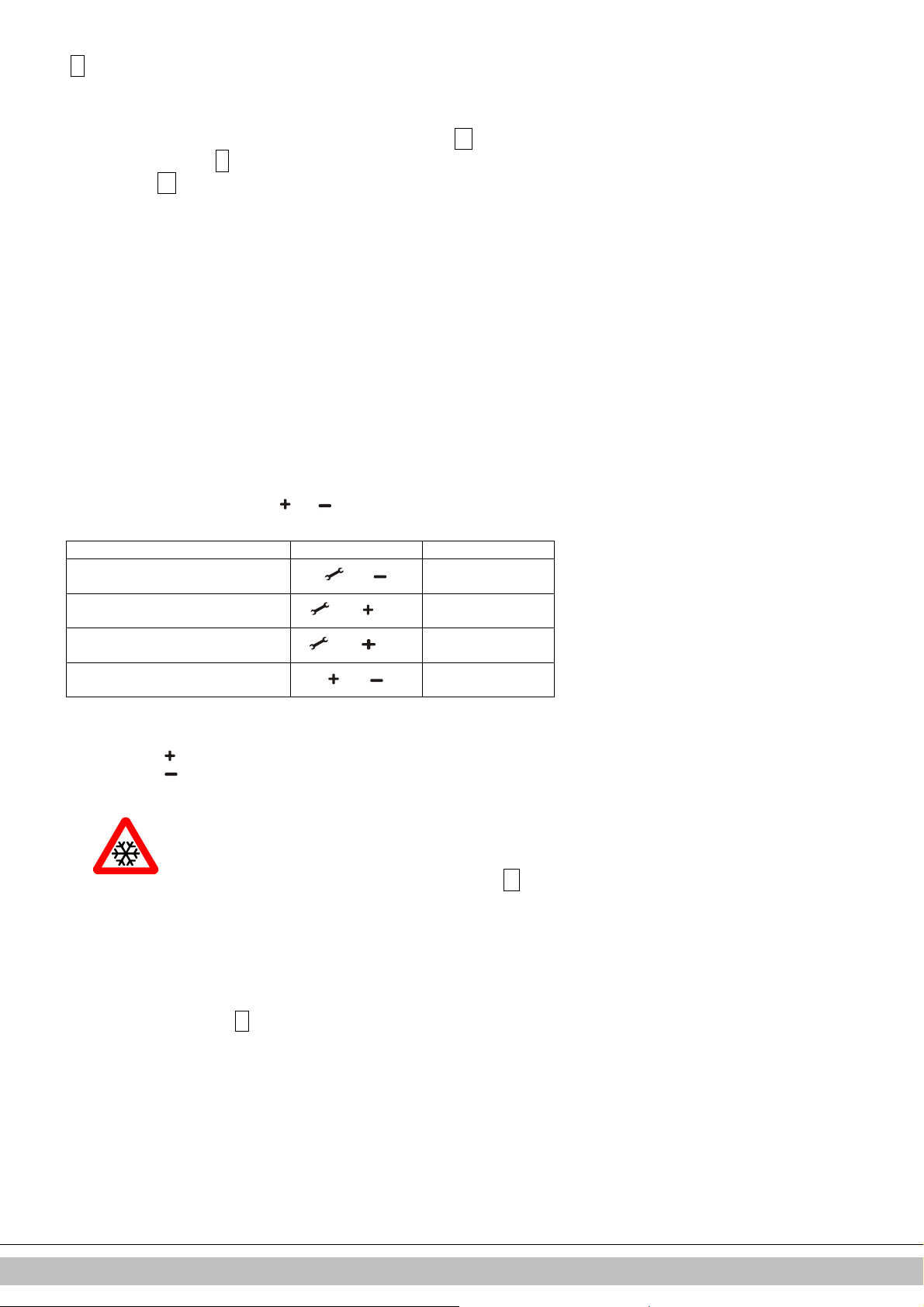
Test programs
Description of program Button combination Display reading
Burner on with minimum DHW
capacity (see parameter d par. 7.2)
Burner on with set maximum CH
power (see parameter 3 par. 7.2)
Burner on with maximum DHW power
(see parameter 3 par. 7.2)
Switching off test program and
During test mode the following data can be read :
• By pressing the button continuously in the display the CH water pressure is shown.
• By pressing the button continuously in the display the ionisation current is shown.
and “L”
and (1x)
and (2x)
Current operation
“h”
“H”
situation
2.5.1 Frost protection
The unit is fitted with frost protection in order to prevent it from
pump will start running until the temperature of the heat exchanger
is sufficiently high. If the frost protection intervenes, the code
be displayed (heating up exchanger).
• If the installation (or a part thereof) can freeze, the coldest place
should be fitted with an (external) frost thermostat on the return
pipe. This must be connected in accordance with the electrical
diagram (see par. 10.3).
Note
When the unit is switched off (
remain active, however a heating request from an (external) frost thermostat will be
ignored.
-
on the service display), the unit frost protection will
7
will
Daikin Europe NV
8
Page 8
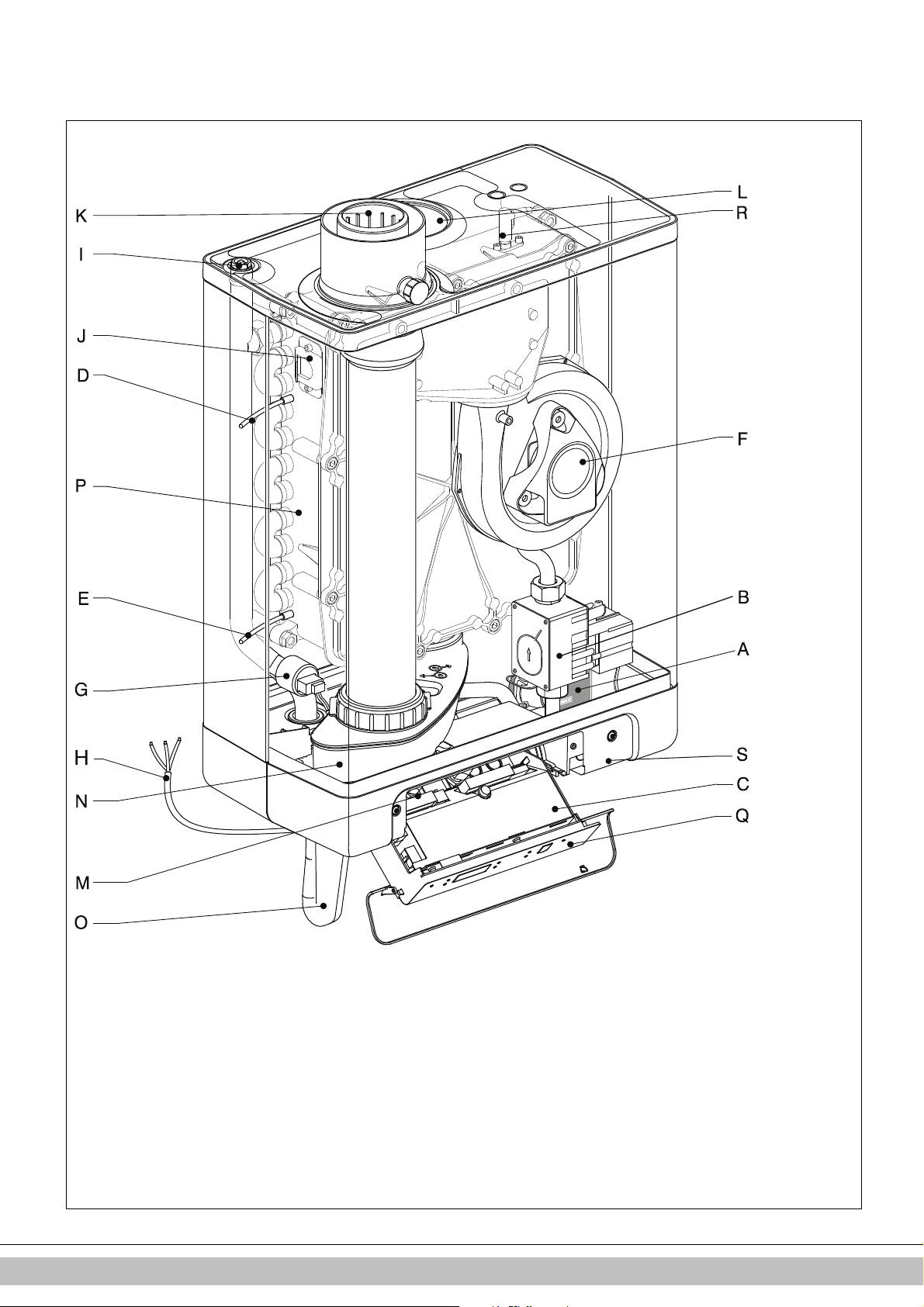
3 MAIN COMPONENTS
Ignition/ionization pin
0207010009
A. Modulating CH pump K. Flue gas/air inlet concentric adapter
B. Gas valve L. Air supply (only when using twin pipe flue system)
C. Burner controller (incl. operating panel) M. Connection block / terminal strip X4
D. Sensor S1 (flow) N. Condensate collector
E. Sensor S2 (return) O. Siphon
F. Fan P. Heat exchanger
G. Pressure sensor central heating Q. Operating panel and display
H. Connection wire 230 V ~ with earthed plug R.
I. Manual air bleed S. Position of data plate
J. Inspection glass
Daikin Europe NV
9
Page 9
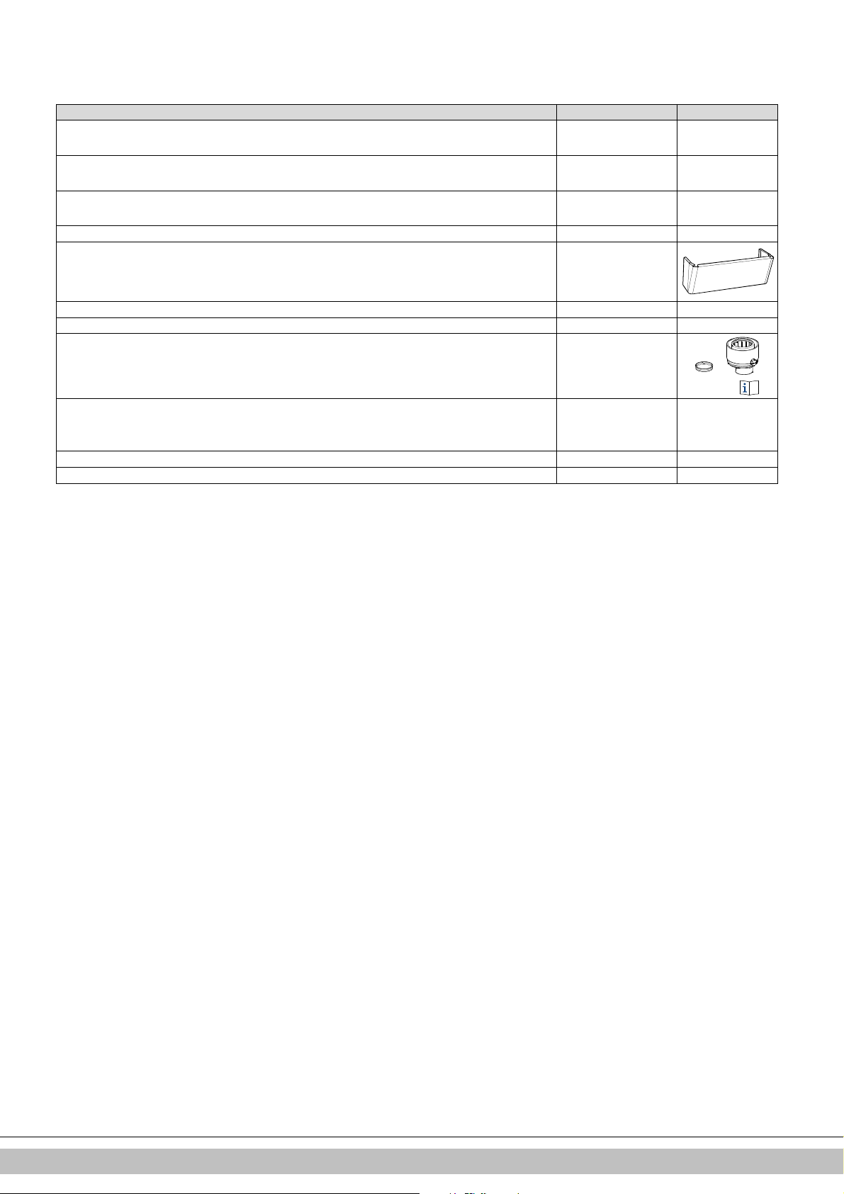
3.1 Accessories
Description Article numbers
B-pack small EKFJS*AA
B-pack middle EKFJM*AA
B-pack large EKFJL*AA
Valve kit EKVK4AA
Cover plate EKCP1AA
Outdoor sensor EKOSK1AA
3-way valve set EK3WV1AA
Flue gas adapter Concentric Ø80x125 EKHY090717
Flue gas adapter Parallel 80 mm
EKHY090707
Propane conversion set EHOBG12ABV1 EKPS075917
Propane conversion set EHOBG18ABV1 EKPS075877
Daikin Europe NV
10
Page 10
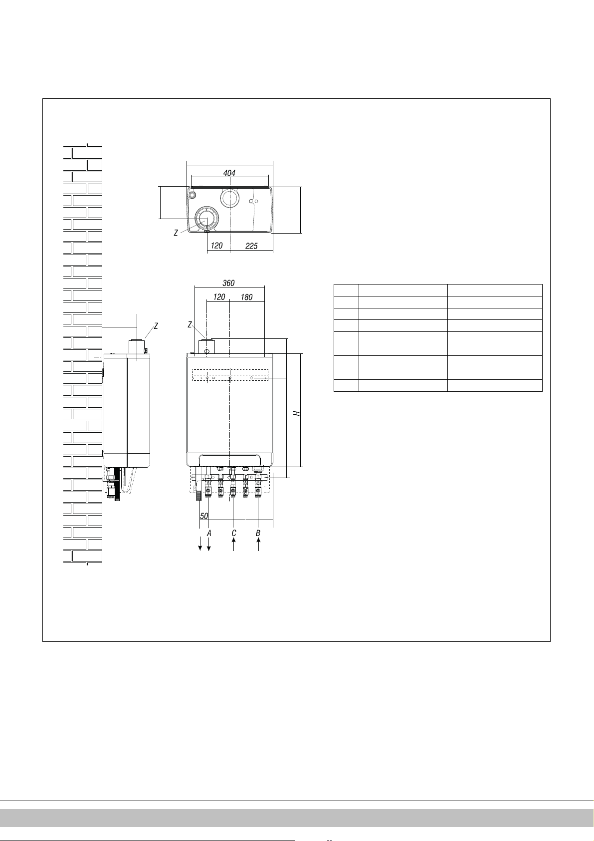
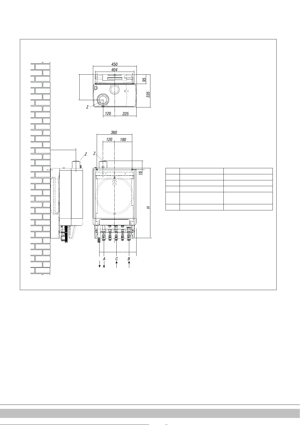
4 INSTALLATION
A = Supply CH
G ¾” (ext)
B = Return CH
G ¾” (ext)
C = Gas G ½” (int)
D = Condense outlet
Ø dn25 (flexible)
h =
517mm
EHOBG
12
ABV1
H =
590mm
EHOBG
12
ABV1
Z = Flue gas outlet/air inlet
Ø60/100 (concentric)
020601005
161
161
450
240
77
135
h
D
130 130
77
4.1 Installation measurements
Boiler mounted directly to the wall:
Unit + mounting bracket
EHOBG18ABV1
EHOBG18ABV1
Daikin Europe NV
11
Page 11
A = Supply CH
G ¾” (ext)
B = Return CH
G ¾” (ext)
C = Gas G ½” (int)
D = Condense outlet
Ø dn25 (flexible)
H = 770mm
EHOBG
12
ABV1
Z = Flue gas outlet/air inlet
Ø60/100 (concentric)
020601006
265
265
77
77
D
50
130 130
Unit connected to B-pack:
Unit + B-pack
EHOBG18ABV1
Daikin Europe NV
12
Page 12
4.2 Installation space
The unit must be installed against a wall with sufficient load bearing capacity.
In case of light wall constructions, there is a risk of resonance noises.
Within 1 meter of the unit, there must be an earthed wall plug.
In order to prevent the condense outlet from freezing, the unit must be installed in a
frost-free room. Preferably ensure there is a space of at least 2 cm next to the boiler.
No free space is required due to danger of singeing.
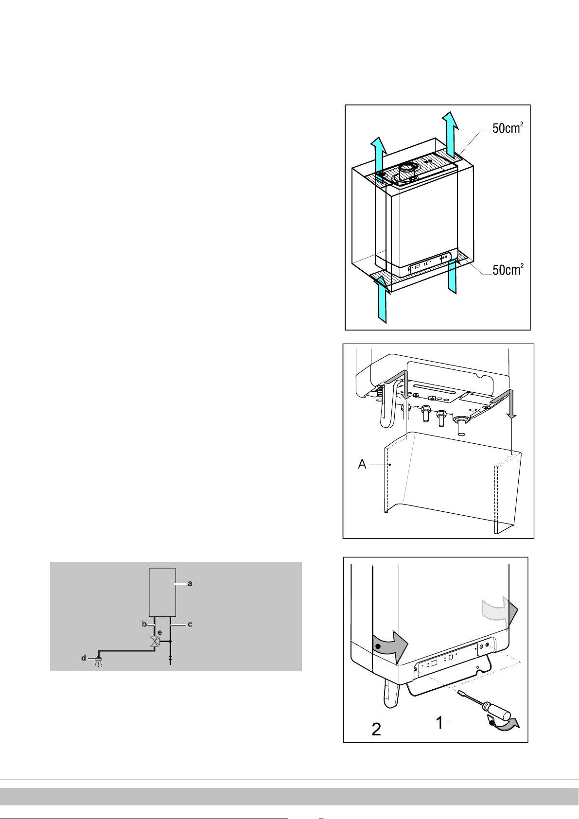
4.2.1 Installing in kitchen cabinet
The unit can be placed between two kitchen cabinets, or inside a kitchen cabinet.
Make sure there is sufficient ventilation at the bottom and the top.
If the unit is installed inside a cabinet, ventilation openings of at least 50 cm2 are
required.
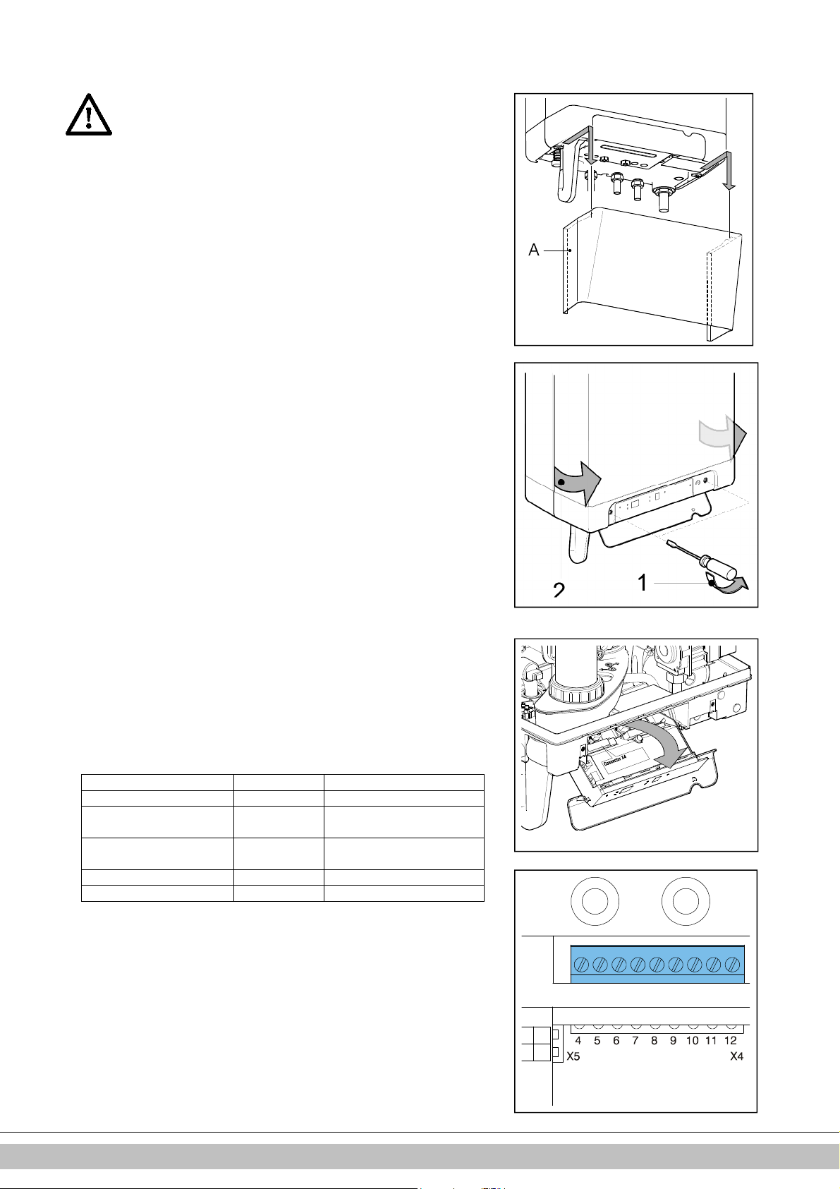
4.2.2 Removing cover plate and front panel
For various activities on the unit, the cover plate and front panel have to be removed
from the unit, if they were installed. Do this as follows:
• If you are using the cover plate (A), remove it to the front.
• Unscrew both screws (1) behind the display window.
• Pull the bottom of the front panel (2) forwards.
Danger: risk of burning
In case of high leaving water set ponts for space heating (eighter a high fixed set point
or a high weather-dependent set point at low ambient temperatures), the heat
exchanger of the boiler can be very hot, for example 70°C.
Beware that in case of a tapping demand, the water can initially have a higher water
temperature than requested.
In this case, it is recommended to install a thermostatic valve to prevent scalding.
This can be done according to the schematics below.
a=boiler, b=DHW from boiler, c= cold water inlet,
d=shower, e=thermostatic valve (field supply)
Daikin Europe NV
13
Page 13
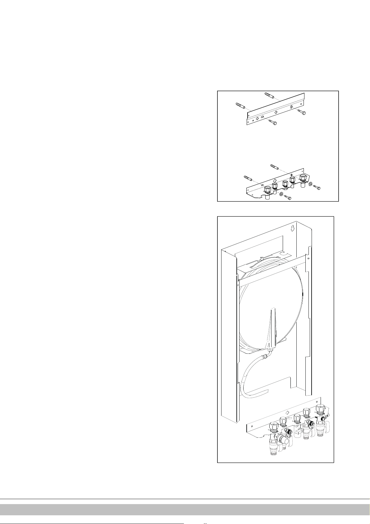
4.3 Assembly
020601020
The boiler can be hung to the wall using :
• the wall suspension strip and a the connection kit EKVK4AA
• a B-pack including an expension vessel and a connection kit.
4.3.1 Assembling suspension strip and assembly bracket
• Make sure the construction of the wall is suitable for hanging the boiler.
• Drill the holes for the suspension strip and the connection kit in the wall
using the template delivered with the boiler.
• Mount the suspension strip and the assembly bracket horizontally on the
wall, using the associated attachment materials.
• The boiler can now be placed on the suspension strip simultaniously sliding
the pipes of the boiler into the valves in the assembly bracket.
4.3.2 Assembling B-pack
• Make sure the construction of the wall is suitable for hanging the boiler and
B-pack.
• Drill the holes for the B-pack kit in the wall using the template delivered
with the boiler.
• Mount the B-pack on the wall using the associated attachment materials.
• Place the assembly bracket in the frame as described in the manual
inclued in the B-pack.
• Connect the flexible hose on the expension vessel and the conenction on
the return valve. Make sure the seal rings are placed !
• The boiler can now be placed on B-pack simultaniously sliding the pipes of
the boiler into the valves in the assembly bracket.
Daikin Europe NV
14
Page 14

4.3.3 Assembling the unit
1. Unpack the unit.
2. Check the content of the packaging, which consists of:
• Unit (A)
• Suspension strip (B)
• Siphon + flexible hose (C)
• Installation instructions
• Operating instructions
• Warranty card
3. Check the unit for any damage: immediately report damages to the supplier.
4. Install the suspension strip.
5. Check whether the compression rings are positioned straight in the couplings of
the assembly bracket.
6. Position the unit: slide it from top to bottom over the suspension strip (B).
Make sure the pipes slide into the compression fittings simultaneously.
7. Tighten the compression fittings onto the assembly bracket.
The nipples and pipes must not rotate with it!
8. Open the display valve and loosen the two screws on the left and right of the
display, and remove the front panel.
9. Assemble the flexible tube (D) onto the outlet of the siphon.
Fill the siphon with water, and slide it as far as possible on top of the condense
output connector (E) under the unit.
10. Seal flexible tube (D) of the siphon, if possible together with the overflow pipe of
the inlet combination and the overflow valve, to the sewage via open connection
(F).
11. Assemble the air supply and the burning gas outlet (see par.5.5).
12. Assemble the cover and tighten the two screws to the left and the right of the
display, and close the display cover.
4.3.4 Apply cover plate (optional)
Suspend the converted top edge of the cover plate from the washers underneath the
bottom of the unit, and slide the cover plate as far back as possible.
Please note: When installing the boiler in combination with a cover plate, the siphon
will extend underneath the cover plate.
Daikin Europe NV
15
Page 15
5 CONNECTING
A
B
020601009
B
A
020601010
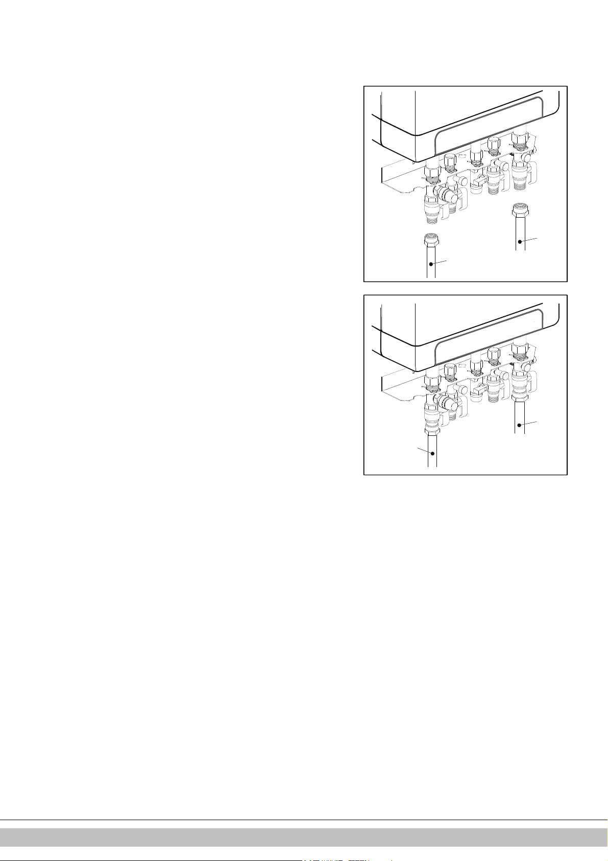
5.1 Connecting CH installation
1. Rinse the CH installation carefully.
2. Fit the supply pipe (A) and return pipe (B) to the connection set.
3. All pipes must be assembled with no electrical current, in order to prevent shocks
from the pipes.
4. Existing connections may not be rotated, in order to prevent leakages.
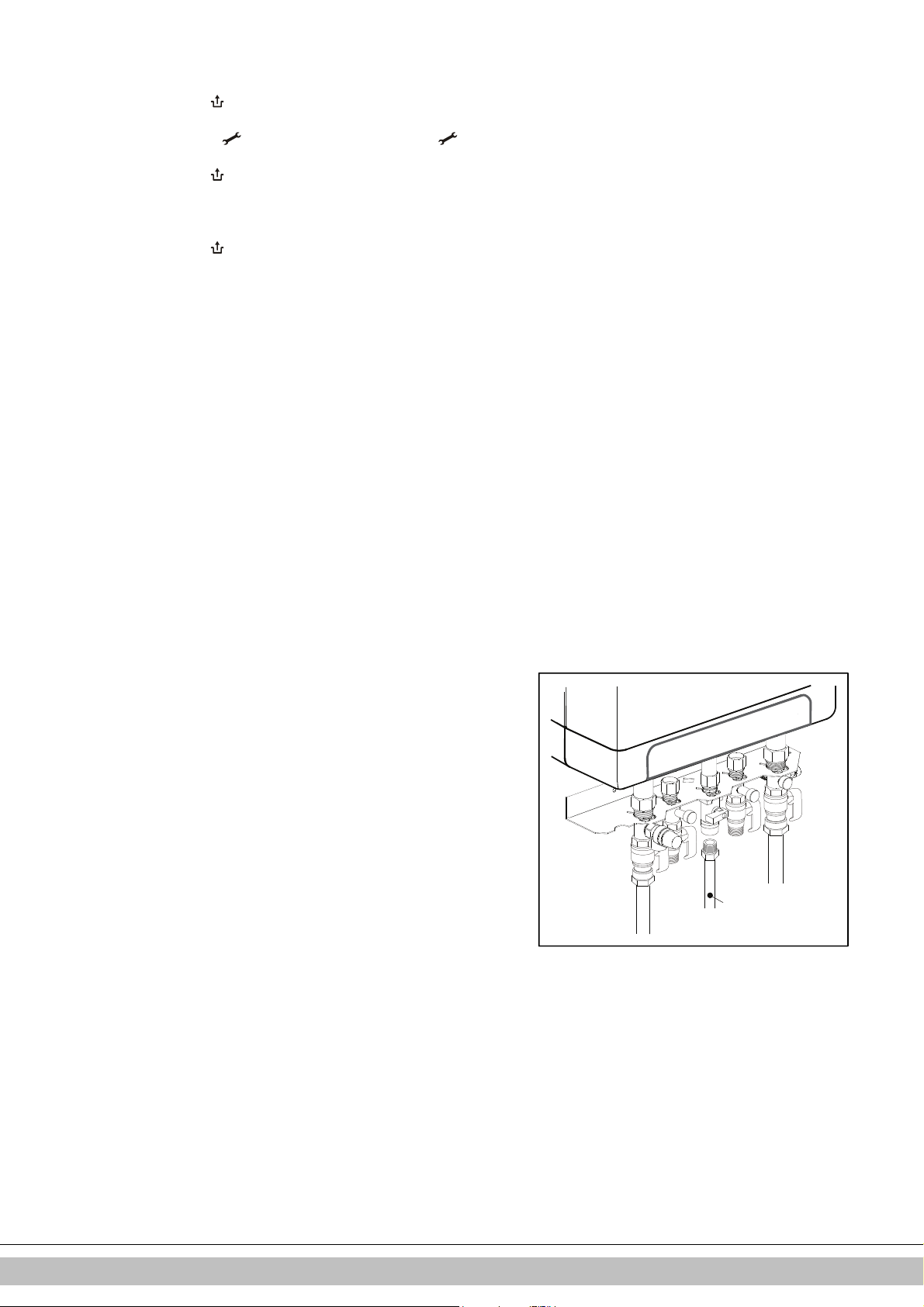
The CH installation must be fitted with:
• A filling/draining tap (A) in the return pipe, immediately underneath the unit.
• A draining tap at the lowest point of the installation.
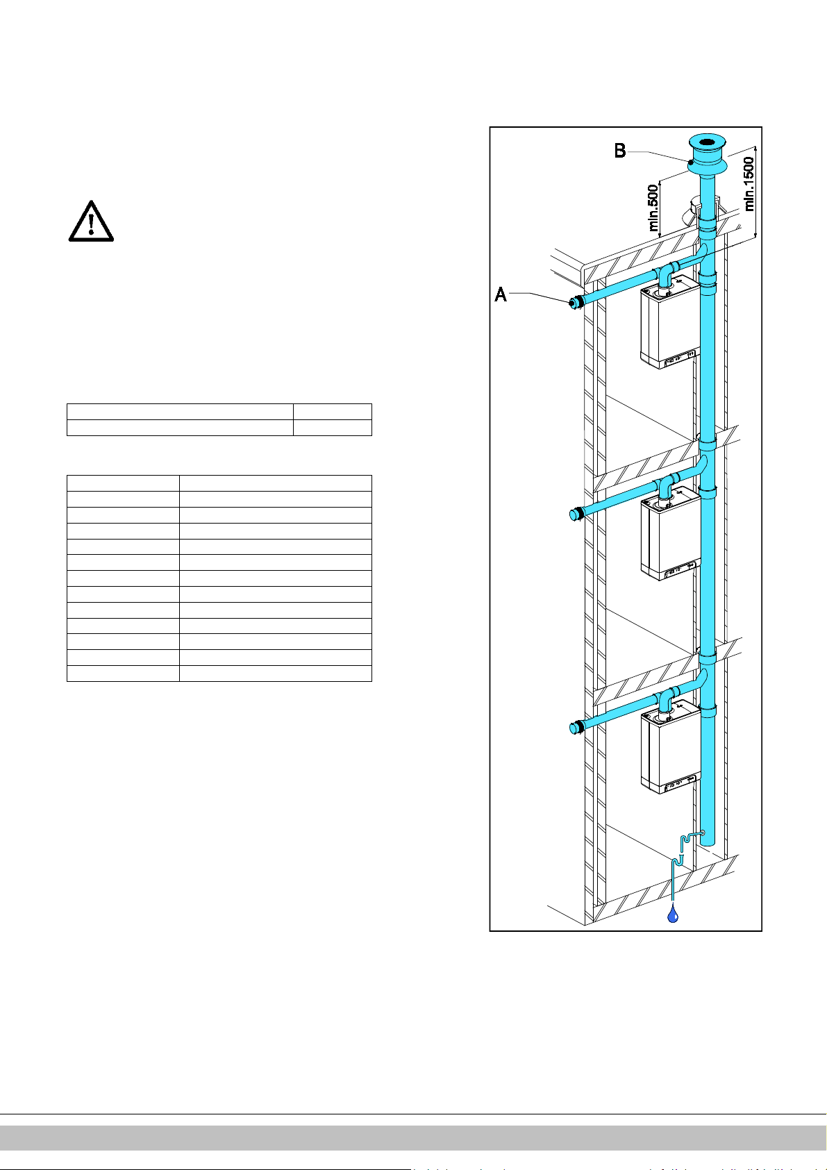
• An overflow valve (B) of 3 bar in the input pipe at a distance of no more than 500 mm
from the unit.
Between the unit and the overflow valve there may be no valve or constriction.
• An expansion vessel in the return pipe (in the B-pack or in the installation).
• A check valve, if there are pipes running up, within close distance of the unit. This
prevents a thermosiphon effect from occurring during tap water operation (a non
spring-operated return valve, must be assembled vertically).
5.1.1 Thermostatic radiator taps
If all radiators are fitted with thermostatic or cable radiator taps, a minimum water
circulation must be safeguarded. See par. 7.4.
Daikin Europe NV
16
Page 16

5.1.2 Dividing CH installation in groups in case of additional heat
sources
Operating principle
If the room thermostat switches off the boiler because another heat source (wood heater,
open fire etc.) heats the room, the other rooms may cool down. This can be resolved by
splitting the CH installation into two zones. The zone with the external heat source (Z2)
can be shut off from the main circuit by means of an electrical shut-off valve. Both zones
are fitted with their own room thermostat.
Please note: This “external heat source” regulation may only be applied if no extra
external tank has to be heated up (installation type 1).
Installation instructions
1. Install the valve in accordance with the connection diagram.
2. Connect the room thermostat of zone 1 to X4 – 6/7.
3. Connect the room thermostat of zone 2 to X4 – 11/12.
4. Change parameter A (see Parameter settings via the service code par. 7.2).
Please note: The room thermostat in zone
thermostat in zone 2 may be an OpenTherm thermostat or an on/off thermostat.
Connection diagram “external heat source” regulation
A. Boiler
B. Electrical shut-off valve 230 V ~
C. Radiators
T1. Room thermostat zone 1
T2. Room thermostat zone 2
Z1. Zone 1
Z2. Zone 2
1 MUST
be an on/off thermostat. The room
Connecting external tank
For the connection of the EHOBG*ABV1 to an indirectly fired tank, a set is available.
This set, EK3WV1AA contains the folowing parst and is delivered upon order:
• Tank sensor
• Locking clip for tank sensor
• Three-way valve set 230V
Connect the tank and three-way valve to the boiler in accordance with the diagram.
Remove the through connection between 9 and 10 to connector X4. Connect the threeway valve to connector X2 and connect the tank sensor or thermostat to connector X4
in accordance with the wiring diagram (see par. 10.2).
Connection diagram indirectly fired tank
C. Unit
D. Tanks
E. CH installation
F. Expansion vessel
G. Safety valve 3 Bar
H. Three-way valve
I. Tank sensor or thermostat
Note
When an on/off tank thermostat is used, the heat request will start when the thermostat is
opened, and it will end when the thermostat closes again.
In case of old installations or domestic hot water circuits which can contain small
particles, install a filter in the domestic hot water circuit.
This pollution could cause a fault during domestic hot water operation.
Daikin Europe NV
17
Page 17
5.2 Connecting electronically
CAUTION
A socket with safety ground must be no further than 1 meter
from the unit.
The socket must be easily accessible.
When installing the unit in a damp space, a fixed connection is
obligatory, by means of an all-pole main switch with a
minimum contact gap of 3 mm.
If the mains cable is damaged or requires replacement for any
other reason, the replacement mains cable must be ordered
from the manufacturer or its representative. In case of any
doubt, contact the manufacturer or its representative.
1. Remove the plug from the socket, when working on the electrical circuit.
2. If there is a cover plate (A), remove it to the front.
3. Unscrew both screws (1) behind the display window.
4. Slide the bottom of the front panel (2) forwards, and remove it.
5. Pull the boiler controller forward. The boiler controller will tip downwards in the
process.
6. Consult par. 10.3 to make the connections.
7. After the required connections have been made, slide the boiler controller back into
the unit and return the cover plate, if you are using one.
8. After making the required connections, connect the unit to the socket with safety
ground.
5.2.1 Electrical connections
Temperature regulation Connector X4 Comments
Room thermostat on/off 6 - 7 Modulating thermostat with
comfort function in use
Outdoor temperature
sensor
DHW tank sensor 9 - 10 Remove yellow wire link
Frost thermostat 6 - 7 Parallel over room thermostat
Daikin Europe NV
11 - 12
8 - 9 -
18
Page 18
5.3
Connect room thermostat
5.3.1 Room thermostat on/off
1. Connect the room thermostat (see par. 10.2).
2. If necessary, set the feedback resistance of the room thermostat to 0.1 A. If unsure,
measure the electrical current and set it accordingly.
The maximum resistance of the thermostat pipe and the room thermostat amounts to a
total of 15 Ohm.
5.3.2 Modulating thermostat, Open Therm
The unit is suitable for connecting a modulating room thermostat, in accordance with
the OpenTherm communication protocol.
The most important function of the modulating room thermostat is to calculate the input
temperature at a required room temperature, in order to make optimal use of the
modulating. At every heating request, the required input temperature is shown on the
display of the unit.
Connect the modulating thermostat (see par.10.2).
If you want to use the tap water on/off switch function of the OpenTherm thermostat, the
tap water comfort function must be set to eco or on.
For more information, consult the manual of the room thermostat.
5.3.3 Modulating room thermostat, wireless
The EHOBG*ABV1 CH boiler is suitable to communicate wireless without
sending/receiving module with the Honeywell room thermostats T87RF1003 Round RF,
DTS92 and CMS927. The CH boiler and the room thermostat must be appointed to each
other:
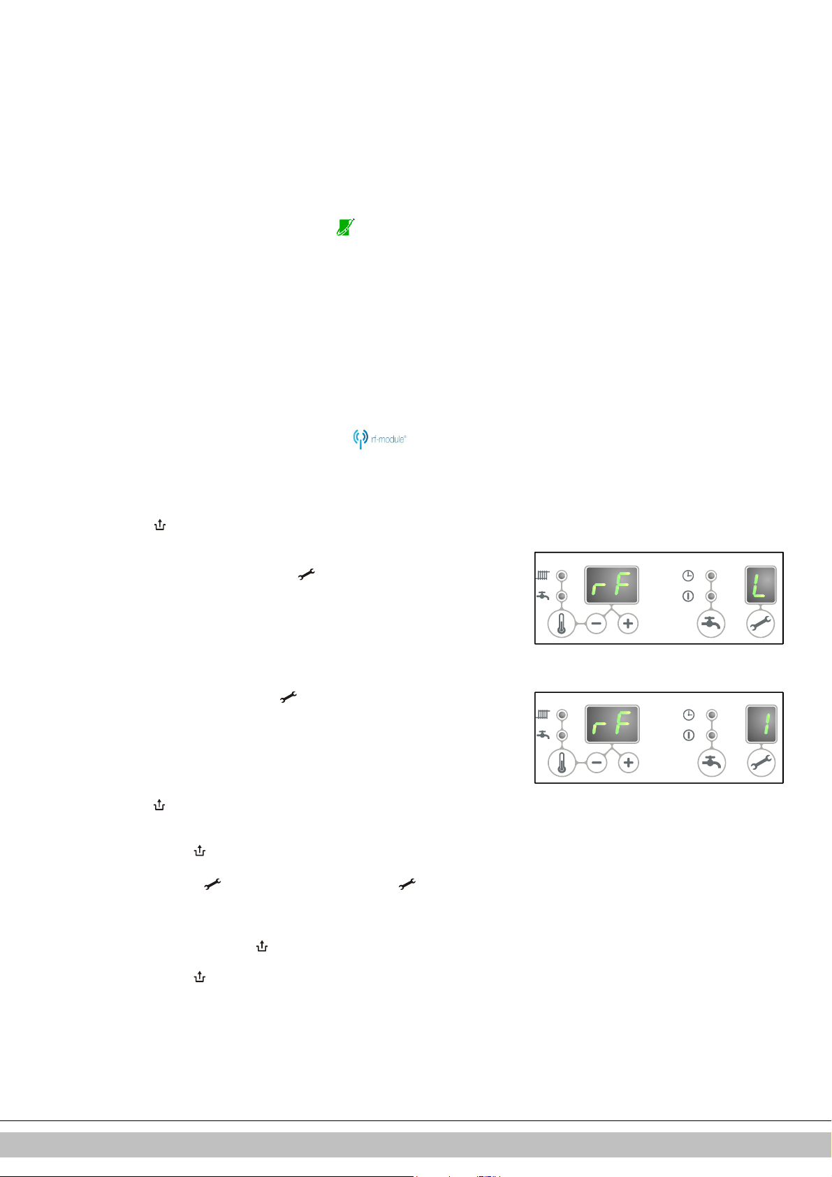
• Press the reset button of the unit for approximately 5 seconds in order to get to the RF-
room thermostat menu.
• One of the following codes will be shown on the display of the unit:
1. rF and L / - : the display above the button shows an L alternated by a –
red led : flashing
The CH boiler has not been appointed. A unit in this operating status, can be linked
by using the method of the appropriate room thermostat.
The method of appointment depends on the type of room thermostat and is
described in the installation and operating instructions of the wireless
room thermostat.
2. rF and L / 1 : the display above button shows an L alternated by a 1
red led : off
The CH boiler has already been appointed. There is already an existing link with
an RF room thermostat. In order to allow a new link to be made, the existing link
will have to be removed.
See: Undo the appointment of an RF room thermostat to the CH boiler.
• Press the reset button to exit the RF room thermostat menu or wait for 1 minute.
Testing the connection between the unit and the RF room thermostat
1. Press the reset button of the unit for approximately 5 seconds to access
the RF room thermostat menu of the boiler controller.
2. Press the service button 1x. On the display above the button, a
will be shown.
3. Set the room thermostat to the test mode (see the installation and operating
instructions of the room thermostat).
4. The red led above the reset button will flash if the appointment has
been carried out correctly.
5. Press the reset button of the unit to exit the RF room thermostat menu of
the boiler controller. You will automatically exit the test mode 1 minute after
the last test message of the RF room thermostat has been received.
t
Daikin Europe NV
19
Page 19
Undo the appointment of an RF room thermostat to the CH boiler.
020601011
E
• Press the reset button of the unit for approximately 5 seconds to
access the RF room thermostat menu of the CH boiler.
• Press the service button 2x. On the display above the button, a C
will be shown.
• Press the reset button of the unit again to remove the existing
appointments. The display of the unit will show rF again, with a flashing
L / - . If required, an RF room thermostat can be appointed to the unit
again.
• Press the reset button of the unit to exit the RF room thermostat menu
or wait for 1 minute.
5.3.4 Outdoor temperature sensor
The unit is provided with a connection for an outdoor temperature sensor. The
outdoor temperature sensor should be used in combination with an on/off room
thermostat.
In principle, any on/off room thermostat can be combined with an outdoor sensor.
Upon request of the room thermostat, the boiler will provide heat until the maximum
set temperature in the boiler has been reached. This maximum set temperature is
automatically regulated via the outdoor sensor, in accordance with the set fuel line in
the boiler.
Connect the room outdoor sensor (see par. 10.2).
For the fuel line setting, see the weather dependent regulation (see par. 7.5).
5.4 Connecting gas
1. Fit the gas valve directly on the 1/2" gas connection of the connection set using
appropriate seal.
2. .Place a gas sieve in the connection for the unit if the gas may be
contaminated.
3. Connect the gas pipe in the gas valve using appropriate seal.
4. Check the gas carrying parts for leakages at a pressure of up to 50 mbar.
5. The gas pipe should be fitted pressure free.
Daikin Europe NV
20
Page 20
5.5 Flue and air supply duct
Don not use screws or parkers to mount the flue system as leakage can
Use water instead. The sealing rubbers can be negatively affected when
5.5.1 Concentric connection 60/100
The boiler is fitted with a flue gas adapter suitable for connecting to a concentric flue gas extractor
system with a diameter of 60/100.
Fit the concentric pipe thoughtfully in the adapter. The built in gaskets ensure there is an air tight
seal.
For the installation of the flue and air supply duct material, see the
manual included with the materials. Contact the
manufacturer of the relevant flue and air supply duct materials for
extensive technical information and specific
assembly instructions.
Make sure that the socket connections of the flue and air supply duct
materials are correctly sealed.
Improper fastening of the flue and the air supply duct
can lead to hazardous situations or result in personal injury.
Check all flue components for tightness.
occur.
Do not use any sort of grease when mounting the pipe system.
grease is applied.
Do not mix any components, materials or ways of coupling from
different manufacturers.
5.5.2 Concentric connection 80/125
If required, the flue gas adapter 60/100 can be replaced by a version for a flue gas extractor
system with a 80/125 diameter.
1. Carefully follow the instruction as provided with the adapter set 80/125.
2. Fit the concentric pipe thoughtfully in the adapter. The built in gaskets ensure there is an air
tight seal.
5.5.3 Parallel connection 80/80
If required, the flue gas adapter 60/100 can be replaced by a version for a parallel flue system (2
pipes) with a 80 mm diameter.
1. Carefully follow the instruction as provided with the adapter set 80.
2. Fit the pipes for the air supply and flue gas thoughtfully in the air inlet opening and flue gas
adapter of the unit. The built in gaskets ensure there is an air tight seal. Make sure that the
connections are not mixed.
Daikin Europe NV
21
Page 21
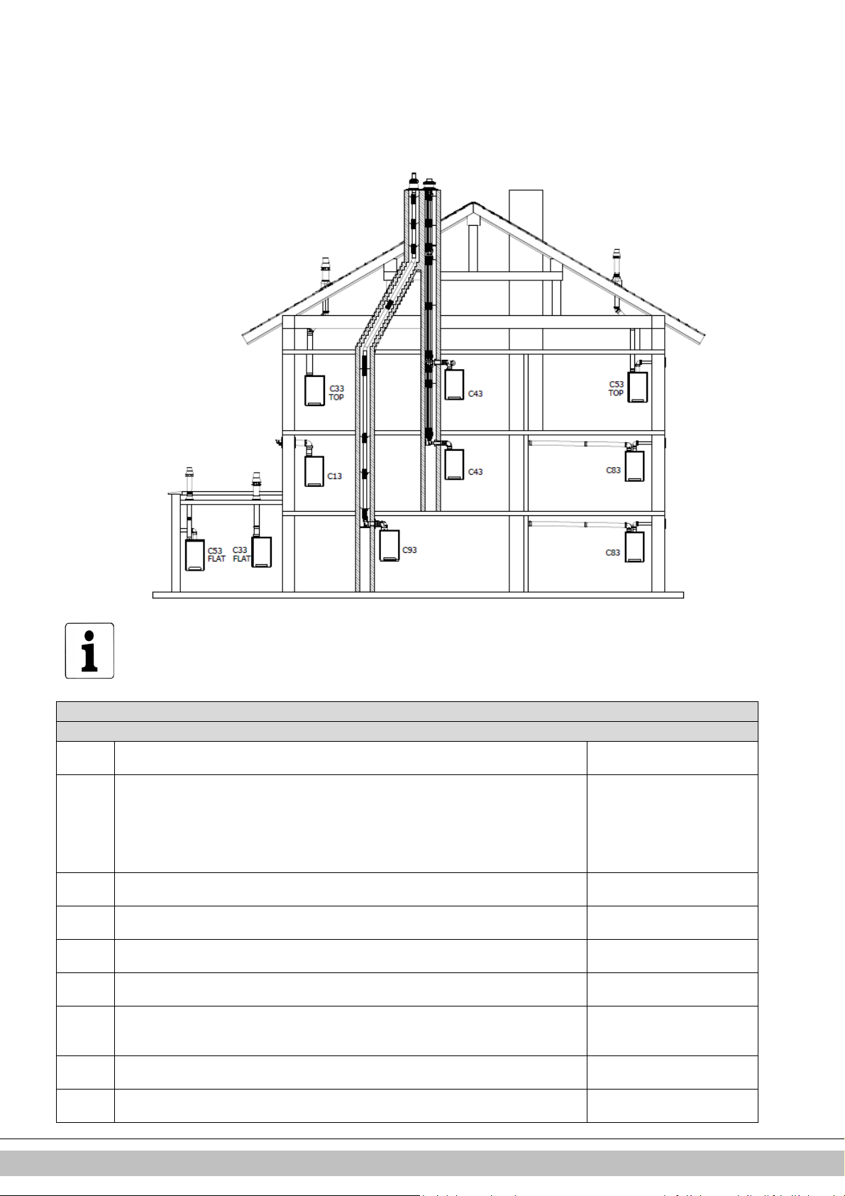
5.6 Outlet systems
Explanation
flue systems
Category in accordance to CE
B23 A flue that evacuates the products of combustion to the
outside of
Make sure the air inlet is open
B33 A flue system which is connected to a common duct system. This common duct system
Make sure the air inlet is open
C13 Horizontal flue system. Discharge in the outside wall.
For example : a wall terminal
C33 Vertical flue system. Flue gas discharge via the roof.
For example : a vertical roof
C43 Joint air supply and flue gas discharge duct (CLV system)
C53 Separate air supply and separate flue gas discharge duct.
C63 Free in the ma
rket available flue material with CE approval
Do not mix flue materials from
C83 Joint air supply and flue gas discharge duct (CLV system)
Only as twin pipe system
C93 Air supply and flue gas discharge duct in shaft or ducted: Concentric. Air supply from
Concentric flue system
Please note that not all flue gas configurations described below are permitted in all
countries. Therefore observe local regulations prior to installation.
The drawings above are a sample and can differ on details.
the room containing the appliance. The combustion air is drawn directly from the room.
consists of a single natural draught flue. All pressurized parts of the appliance containing
products of combustion are completely enclosed by parts of the appliance supplying
combustion air. Combustion air is drawn into the appliance from the room by means of a
concentric duct, which encloses the flue. The air enters through defined orifices situated
in the surface of the duct.
Inlet opening for the air supply is in the same pressure zone as the discharge
Inlet opening for the air supply is in the same pressure zone as the discharge
Twin-pipe or concentric
Discharging into different pressure zones
and complies to the demands
and complies to the demands
through the facede.
terminal.
Discharging into different pressure zones
existing duct. Flue gas discharge via the roof. Air supply and flue gas discharge are in
Daikin Europe NV
different suppliers.
between the boiler and the
22
Page 22
the same pressure zone.
duct.
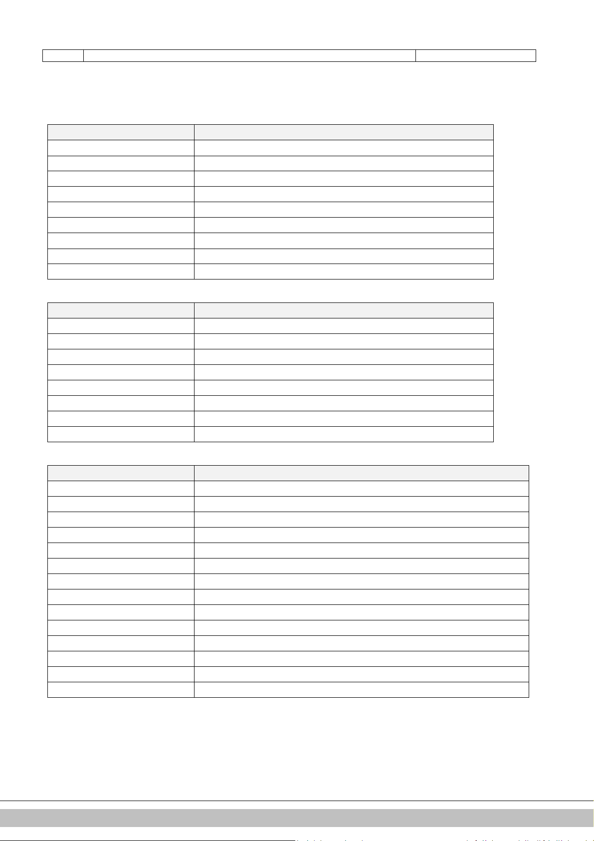
5.7 Flue material
The following flue materials can be ordered at Daikin.
Also visit the website: fluegas.daikin.eu
C13
Art.no. Description
EKFGP2978
EKFGP4651
EKFGP4652
EKFGP4660
EKFGP4661
EKFGP2977
EKFGP4664
EKFGP4631
EKFGP4667
Wall Terminal Kit PP/GLV 60/100
Extension PP/GLV 60/100 x 500mm
Extension PP/GLV 60/100 x 1000mm
Elbow PP/GLV 60/100 90°
Elbow PP/GLV 60/100 45°
Wall Terminal Kit low profile PP/GLV 60/100
Elbow PP/GLV 60/100 30°
Wall Bracket Dn.100
Measurement Tee with Inspection Panel PP/GLV 60/100
C33
Art.no. Description
EKFGP4631 Wall Bracket Dn.100
EKFGP4651 Extension PP/GLV 60/100 x 500mm
EKFGP4652 Extension PP/GLV 60/100 x 1000mm
EKFGP4660 Elbow PP/GLV 60/100 90°
EKFGP4661 Elbow PP/GLV 60/100 45°
EKFGP4664 Elbow PP/GLV 60/100 30°
EKFGP4667 Measurement Tee with Inspection Panel PP/GLV 60/100
EKFGP6837 Roof Terminal PP/GLV 60/100 AR460
C53
Art.no. Description
EKFGP4651 Extension PP/GLV 60/100 x 500mm
EKFGP4652 Extension PP/GLV 60/100 x 1000mm
EKFGP6837 Roof Terminal PP/GLV 60/100 AR460
EKFGW4085 Elbow PP 80 90°
EKFGW4086 Elbow PP 80 45°
EKFGV1102 Chimney Conection Set 60/100 Air Intake Dn.80 C53
EKFGP4660 Elbow PP/GLV 60/100 90°
EKFGP4661 Elbow PP/GLV 60/100 45°
EKFGP4664 Elbow PP/GLV 60/100 30°
EKFGP4667 Measurement Tee with Inspection Panel PP/GLV 60/100
EKFGP4631 Wall Bracket Dn.100
EKFGW4001 Extension PP 80x500
EKFGW4002 Extension PP 80x1000
EKFGW4004 Extension PP 80x2000
Daikin Europe NV
23
Page 23

C93
Art.no. Description
EKFGP4678 Chimney Connection 60/100
EKFGP1856 Flex Kit PP Dn.60-80
EKFGP6340 Extension Flex PP 80 L=10 M
EKFGP6344 Extension Flex PP 80 L=15 M
EKFGP6341 Extension Flex PP 80 L=25 M
EKFGP6342 Extension Flex PP 80 L=50 M
EKFGP6324 Connector Flex-Flex PP 80
EKFGP4664 Elbow PP/GLV 60/100 30°
EKFGP4661 Elbow PP/GLV 60/100 45°
EKFGP4660 Elbow PP/GLV 60/100 90°
EKFGP6333 Spacer PP 80-100
EKFGP4667 Measurement Tee with Inspection Panel PP/GLV 60/100
EKFGP4631 Wall Bracket Dn.100
EKFGP4651 Extension PP/GLV 60/100 x 500mm
Daikin Europe NV
24
Page 24
5.8 Connection to a flue system without air inlet (B23, B33)
CAUTION
• Make sure the boiler room complies to the regulatory
requirements for connecting to a flue system in
accordance to B23 or B33
• When connection the boiler to a flue system in
accordance to B23 or B33 the electrical protection
class is IP20 instead of IP44
General assembly
1. Slide the combustion gas outlet pipes into each other.
From the unit, every pipe has to be slid into the previous one.
Mount a non-vertical combustion gas outlet pipe on a slope towards the unit (min. 5mm/m).
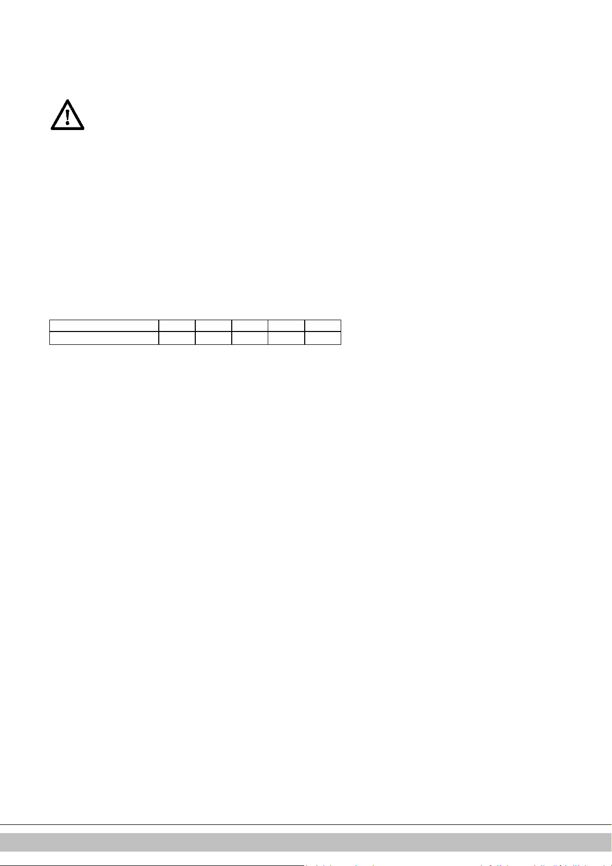
5.8.1 Permitted pipe lengths at parallel air supply and flue tube systems
Permitted pipe lengths B23 and B33 when applying Ø80 mm
C13 C33 C43 C53 C83
EHOBG12 & 18ABV1
100 m 100 m 100 m 100 m 100 m
Daikin Europe NV
25
Page 25
5.9 Connection to a sealed flue system.
5.9.1 Pipe lengths
As the resistance of the flue tube and air supply pipes increases, the power of the unit will
decrease. The maximum permitted power reduction is 5%.
The resistance of the air supply and the combustible gas outlet depends on the length, diameter
and all components of the pipe system. Per unit category, the total permitted pipe length has been
indicated for the air supply and the combustible gas outlet.
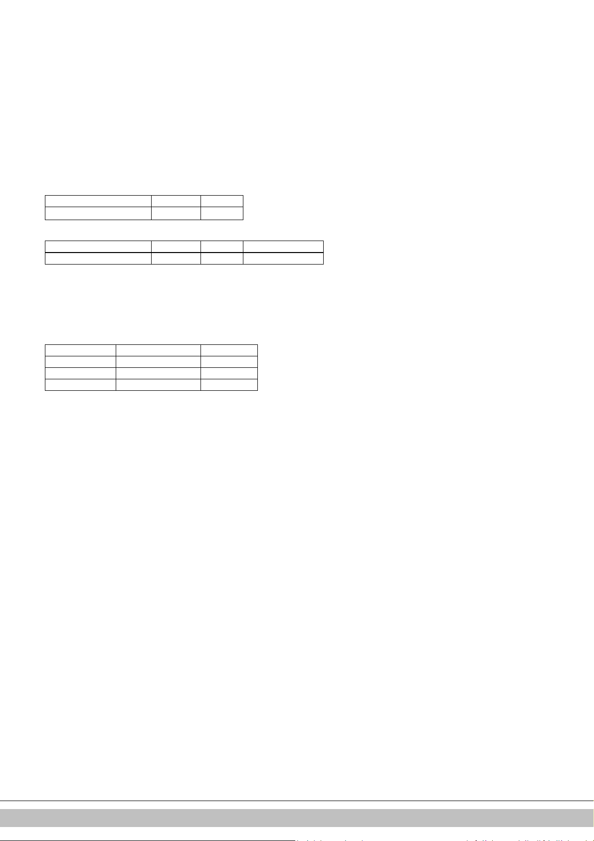
5.9.2 Permitted pipe lengths in concentric flue tube systems
Permitted pipe lengths when applying concentric 60/100
C13 C33
EHOBG12 & 18ABV1
Permitted pipe lengths when applying concentric 80/125
C13 C33 C93
EHOBG12 & 18ABV1 29 m 29 m See par 5.9.8
Contact the manufacturer for test calculations for the resistance of the air supply and
combustible gas outlet pipe and the wall temperature at the end of the combustible gas
outlet pipe.
Replacement lengths
Bend 90° R/D=1 2 m
Bend 45° R/D=1 1 m
Knee 90° R/D=0.5 4 m
Knee 45° R/D=0.5 2 m
General assembly:
For all outlets, the following assembly applies:
1. Slide the concentric combustion gas outlet pipe and air supply pipe.
2. Slide the concentric pipes into each other.
From the unit, every pipe has to be slid into the previous one.
3. Mount a non-vertical combustion gas outlet pipe on a slope towards the unit
(min. 5mm/m).
4. Fit the assembly brackets in accordance with the assembly instructions of the supplier of
the air supply/flue tube system.
10 m 11 m
Daikin Europe NV
26
Page 26
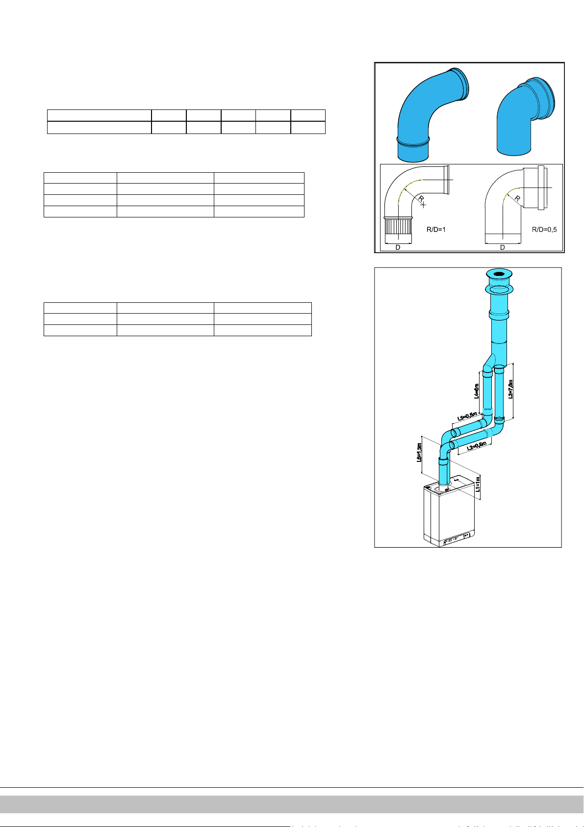
5.9.3 Permitted pipe lengths at parallel air supply and flue tube systems
Permitted pipe lengths when applying Ø80 mm (total of flue pipe and air intake pipe
together).
C13 C33 C43 C53 C83
EHOBG12 & 18ABV1
Replacement lengths
Bend 90° R/D=1 2 m
Bend 45° R/D=1 1 m
Knee 90° R/D=0.5 4 m
Knee 45° R/D=0.5 2 m
Calculation example
Pipe Pipe lengths Pipe length total
Flue gas outlet L1 + L2 + L3 + 2x2 m 13 m
Air supply L4 + L5 + L6 + 2x2m 12 m
Note:
The total pipe length is: sum of the straight pipe lengths + sum of the replacement pipe
lengths of bends/knees amounts to a total of 25 meters. If this value is less than the
maximum permitted pipe length, the flue gas outlet meets the requirements on this point.
100 m 100 m 100 m 100 m 100 m
Daikin Europe NV
27
Page 27
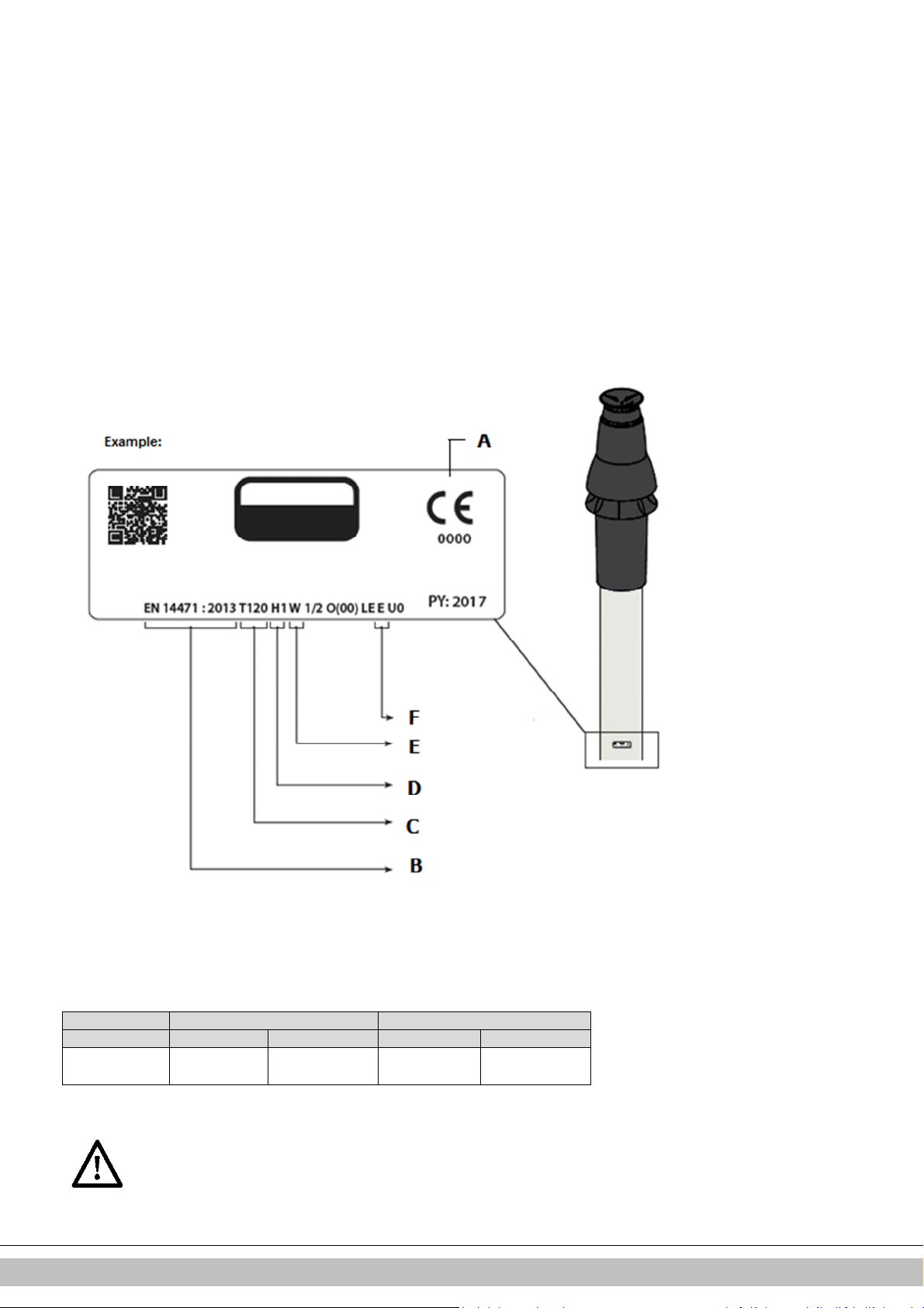
5.9.4 Free in the market available flue gas materials (C63).
+0,3
- 0,7
+0,3
- 0,7
+ 2
- 0
+0,3
- 0,7
+ 2
- 0
The properties of the combustion determine the choices for the flue material.
The standards EN 1443 and EN 1856-1 provide the necessary information for choosing the
flow material by means of a sticker including an identification string.
The Identification string contains the following information:
A CE marking
B The standard to comply to: Metal, EN 1856-2
Plastic, EN 14471
The ID string needs to contain the following information:
C Temperature class : T120
D Pressure class : Pressure (P) or High Pressure (Hi)
E Resistance class : W (Wet)
F Resistance class in case of fire : E
Dimensions C63 Flue system (external dimensions in mm)
Parallel Concentric 80/125 Concentric 60/100
Flue pipe Air inlet Flue pipe Air inlet
ø 80
ø 80
ø 125
ø 60
ø 100
Flue materials of different markings must not be combined !
Daikin Europe NV
28
Page 28
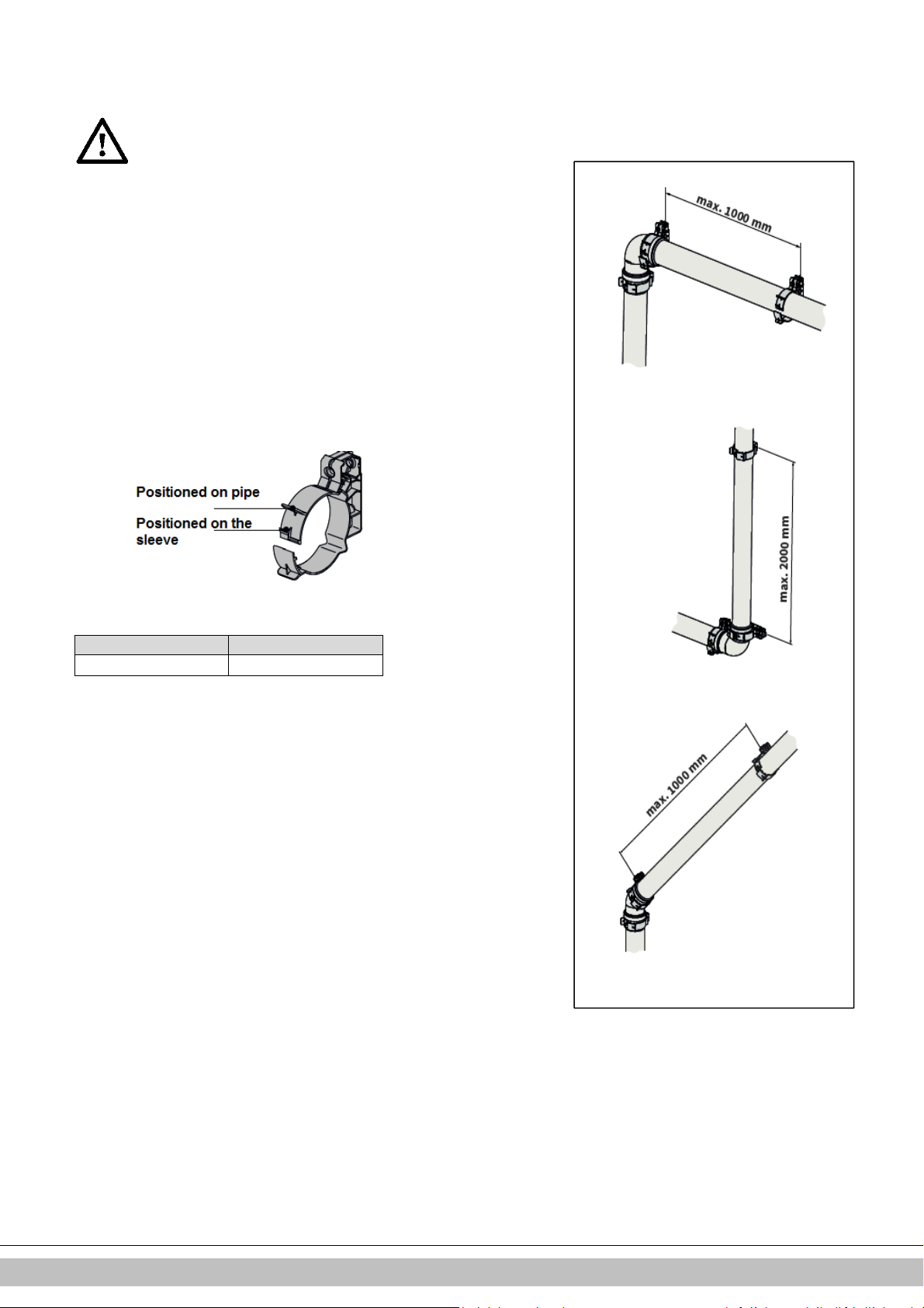
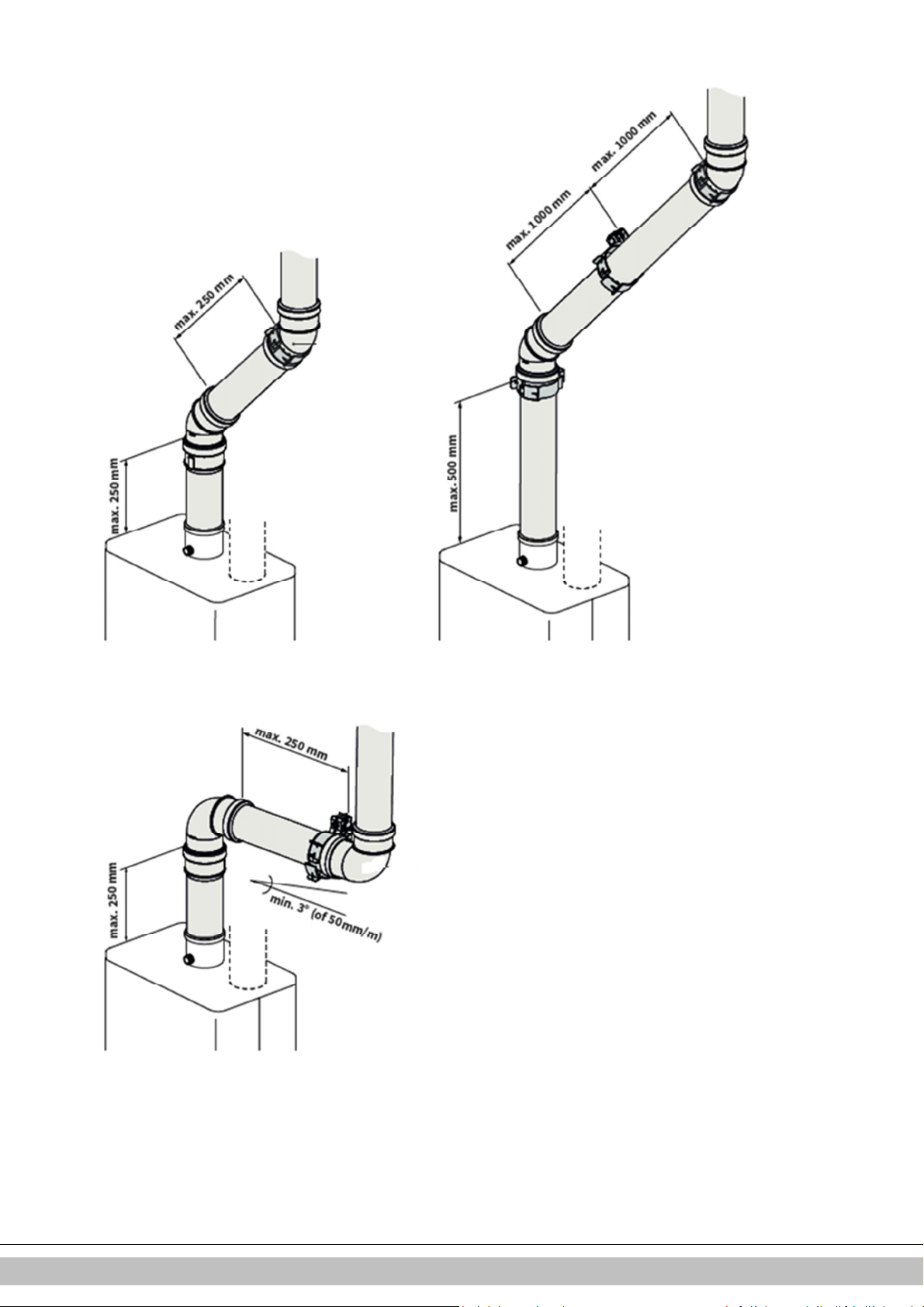
5.9.5 Securing the flue system
oiler:If the lenght of the pipes before and after
IMPORTANT
• These regulations are typical for both concentric and parallel flue
systems.
• The flue system must be secured to a solid structure.
• The flue system should have a continuous fall back to the boiler (1.5° to
3°). N.B. Wall terminals must be installed leveled..
• Only use accompanying brackets.
• Every elbow must be secured by using the bracket.
Exception at connecting on b
the first elbow, are no more than 250 mm, the second element after the
first elbow has to contain a bracket.
Note: The bracket must be positioned on the elbow!
• Every extension must be secured per metre with a bracket.
This bracket must not be clamped around the pipe ensuring free
movement of the pipe..
• Make sure bracket is locked into the correct position depending on the
position of the bracket on the pipe or elbow:
• Do not mix flue parts or clamps of different suppliers.
Max. distance between clamps
Vertical Others
2000 mm 1000 mm
• Divide the lengths between the brackets evenly.
• Every system must contain at least 1 bracket.
• Position the first clam at a maximum of 500 mm from the boiler.
Daikin Europe NV
29
Page 29
Daikin Europe NV
30
Page 30
5.9.6 Air supply from the facade and a roof outlet with communal
•
exhaust system
Unit category: C83
An air supply from the facade and a roof outlet with communal exhaust system is
permitted.
IMPORTANT
The air supply in the facade must be fitted with an inlet
roster (A).
• The communal output system must be fitted with a traction
extractor hood (B).
• If the communal output system is situated in the outdoors,
the output pipe must be double-walled or insulated.
Permitted pipe length
Combustion gas outlet pipe between the unit and the communal output system and
air supply pipe between the unit and the inlet roster together:
EHOBG12ABV1 100 m
EHOBG18ABV1 100 m
The minimum diameters of the communal output system based on vacuum
Flue tube diameter
Number of units EHOBG12ABV1 & EHOBG18ABV1
2 130
3 150
4 180
5 200
6 220
7 230
8 250
9 270
10 280
11 290
12 300
Communal combustible gas outlet
The output of the combustion gas outlet can be made in any location on the sloping
roof surface, providing the outlet in the roof surface has the same orientation as the
air supply in the facade. On a flat roof, the outlet of the combustion gas outlet must be
made in the “free” outlet area.
Fit a condense output.
Note
The communal outlet is certified in combination with the unit.
Daikin Europe NV
31
Page 31

5.9.7 Combined flue outlet/air inlet system
Unit category : C43
IMPORTANT
• A roof outlet through a Combination Air Supply-combustion gas
outlet system is permitted.
• For the communal combustion gas outlet hood and air supply
hood, a declaration of no objection or a Gas certificate from the
Gastec Gas institute is required.
• The passage of the pressure balancing opening at the bottom of
the communal air supply and flue gas outlet system is equal to
0.44 times the flue gas outlet surface.
The communal air supply and the communal output of the combustion gases may be
carried out concentrically or separately.
Permitted pipe length
For parallel: Air supply and combustion gas outlet together, excluding the length of the
combi feedthrough.
For concentric: total pipe length, excluding the length of the combi feedthrough.
EHOBG12ABV1 100 m 10 m 29 m
EHOBG18ABV1 100 m 10 m 29 m
The minimum diameters of the communal air supply and flue tube system based
on the continuation sheet 2001-02 inspection requirements no, 138 of Gastec.
EHOBG12ABV1 & EHOBG18ABV1
Number
of units Concentric Parallel
Flue gas Air supply Flue gas Air supply
2 135 253 135 214
3 157 295 157 249
4 166 311 166 263
5 175 328 175 278
6 184 345 184 292
7 193 362 193 306
8 201 376 201 318
9 210 393 210 332
10 219 410 219 347
11 228 427 228 361
12 237 444 237 375
13 246 461 246 389
14 255 478 255 404
15 264 494 264 418
16 272 509 272 431
17 281 526 281 445
18 290 543 290 459
19 299 560 299 473
20 308 577 308 488
Parallel Concentric
60/100
Concentric
80/125
Daikin Europe NV
32
Page 32

5.9.8 Concentric horizontal flue gas outlet, vertical part airsurrounded by shaft
Unit category : C93
A flue tube system according to C93 (C33) is permitted when using CE approved
flue material or the flue material provided by Daikin.
The ponts below have to be considered.
General
• Flue outlet in shaft with 60 or 80 mm diameter (rigid or flexible).
• When using plastic flue pipe materials, a minimum temperature class of T120
applies.
• The transfer bend between concentric and vertical flue connection in the shaft
must be supported in accordance with supplier instructions. The assembly
instruction of the manufacturer for the flue system must always be followed in full.
• In existing installations, the shaft must be inspected and if necessary cleaned
before the new installation is commissioned.
• The tightness of the shaft towards living spaces must be ensured.
Permitted pipe length and system requirements
When a shaft (e.g.a brickwork chimney) has the purpose of air intake the following
requirements are applicable.
Flue gas pipe
Diameter (mm)
(rigid or flexible)
DN 60 115 x 115 135 11
Dimension shaft [mm] Max. length [mtr]
Square Round
DN 80 135 x 135 155 29
.
Daikin Europe NV
33
Page 33

6 COMMISSIONING THE UNIT AND THE INSTALLATION
6.1 Filling and air purge of unit and installation
6.1.1 CH system
1. Insert the unit's plug into a socket.
The unit may carry out a self-check:
The unit will then go into the off setting:
pressure is shown on the temperature display.
2. Connect the filling hose to the fill/drain tap and fill the installation with clean drinking
water, up to a pressure between 1 and 2 bar if the installation is cold (to be read
from the temperature display).
3. Aerate the system with the manual aerator (A).
Upon request, an automatic aerator can be fitted onto the unit instead of the manual
aerator.
4. Aerate the installation with the manual aerators on the radiators.
5. Top up the CH installation if the pressure has dipped too low due to the aeration.
6. Check all couplings for leaks.
7. Check whether the siphon is filled with water.
In case of a CH pressure lower than 0.5 bar, the CH
pressure will be displayed flashing on the display.
In the off setting, the CH pressure will be displayed.
WARNING
If the siphon is not filled with water, combustion gases
may be released into the room.
WARNING
If an additive is added to the CH water, it must be
suitable for the materials used in the unit, such as
copper, brass, stainless steel, steel, plastic and rubber.
The additive should preferably have a KIWA/ATA/Atest
certification.
6.1.2 DHW supply (only applicable in indirectly fired tank)
1. Open the main tap to bring the warm water section up to pressure.
2. Aerate the tank and the pipe system by opening a warm water tap. Leave the tap
open until all air has flowed out of the system.
3. Check all couplings for leaks.
2
(on service display).
-
(on service display) and the CH
6.1.3 Gas supply
1. Aerate the gas pipe with the initial pressure measuring nipple (D) on the gas block.
2. Check all couplings for leaks.
3. Check the initial pressure and offset pressure (see par. 7.7).
34
Daikin Europe NV
Page 34
6.2 Commissioning the unit
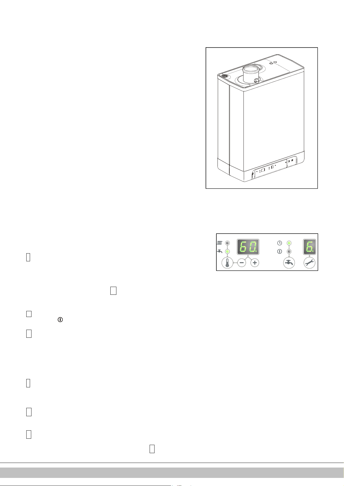
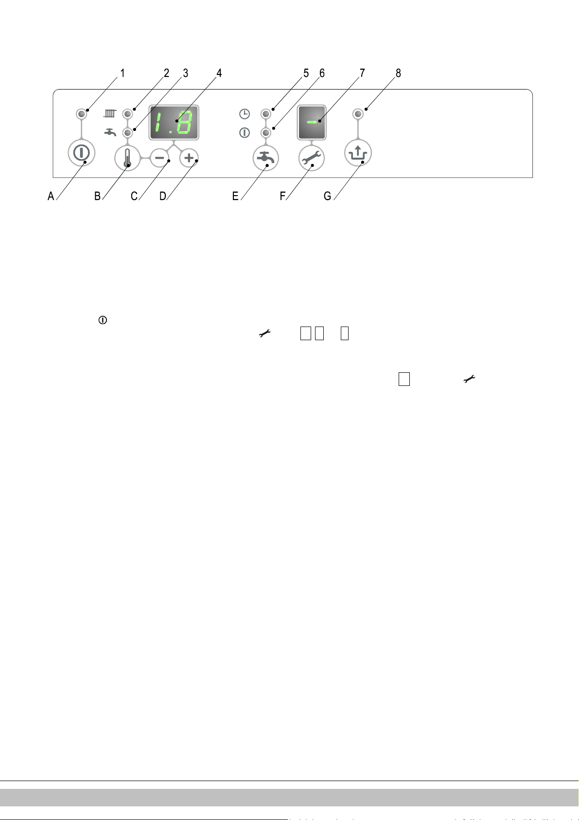
Reading
Operating
1
On/off A
On/off button
2
CH operation or setting maximum CH temperature
B Tap/CH button to set the required temperature
3
Tap
operation or setting tap temperature
C - button
4
Required temperature CH or tap water in °C / pressure CH water in bar / malfunction code
D + button
5
Tap comfort function eco (n/a for
EHOBG
*
ABV1 units) E
Tap comfort function off / eco / on (n/a for
EHOBG
*
ABV1 units)
6
Tap comfort function on (n/a for
EHOBG
*
ABV1 units) F
Service button / actual temperature during heat request
7
Operating
code G
Reset button
8
Blinking
in case of a malfunction
After the following actions have been completed, the unit may be commissioned.
1. Press the button to commission the unit.
The heat exchanger will be heated up, and on the service display,
and/or OpenTherm regulation).
2. Set the pump setting depending on the set maximum power and the water side resistance of the installation. For the water head of the
pump and the loss of pressure of the unit: (see par. 7.4).
3. Set the room thermostat higher than the room temperature. The unit will now go into CH operation:
4. Fire up the installation.
5. Check the temperature difference between the input and return of the unit and the radiators.
This should be approximately 20°C. Set the maximum power on the service panel for this purpose (see par. 7.3). If necessary, set the
pump setting and/or radiator shut-off valves. The standard setting of the pump is setting 3. The minimum feed-through amounts to:
155 l/h at a set power of 5.4 kW
510 l/h at a set power of 17.8 kW
6. Switch the unit off.
7. Purge the air from the unit and the installation after cooling down (top up if necessary).
8. Check the heating and the hot water provision for the correct functioning.
9. Instruct the user on the filling, air purging and functioning of the heating and the hot water provision.
Comments
• The unit is fitted with an electronic boiler controller which ignites the burner relay and
continuously monitors the flame, at every heat request from the heating or from the
hot water provision.
• The circulation pump will run at every heat request for the heating. The pump has a
post-running time of 1 minute. The post-running time can be changed upon request
(see par. 7.3).
• The pump will run automatically 1 time per 24 hours, for 10 seconds, in order to
prevent it from getting stuck. This automatic switching on of the pump takes place 24
hours after the last heating request. To change the time, the room thermostat must
be turned up for a moment at the requested time.
• For the hot water provision, the pump will not run.
3., 4
and 7 appear (Depending on status of external eco switch
5
on the service display.
Daikin Europe NV
35
Page 35
6.3 Switching off the unit
CAUTION
Drain the unit and the installation, if the mains
electricity supply is interrupted and there is a risk of
freezing.
1. Remove the plug from the socket.
2. Drain the unit with the filling/draining tap.
3. Drain the installation at the lowest point.
4. Shut the main tap for the water supply from the hot water section.
5. Drain the unit by loosening the domestic hot water couplings under the unit.
6. Empty the siphon.
6.3.1 Frost protection
• In order to prevent the condense outlet from freezing, the unit must be installed in a
frost-free room.
• The unit is fitted with frost protection in order to prevent it from freezing. If the
temperature of the heat exchanger drops too low, the pump will start running until
the heat exchanger has warmed up sufficiently. If there is a risk of the installation
(or a part thereof) freezing, the coldest place should be fitted with an (external)
frost thermostat on the return pipe. This must be connected in accordance with the
wiring diagram (see par. 10.3).
Note
If an (external) frost thermostat has been fitted on the installation and has been
connected to the unit, it will not be active if the unit on the operating panel is switched
off (
-
on service display).
Daikin Europe NV
36
Page 36

7 SETTING AND ADJUSTMENT
The functioning of the unit can be influenced by means of the (parameter) settings in the boiler
controller. Part of this can be configured directly via the operating panel, another part can only
be adjusted by means of the installers code.
7.1 Direct via operating panel
The following functions can be operated directly.
Unit on/off
The button activates the unit.
When the unit is active, the green LED above the button will be lit. When the unit is
off, one bar will be lit on the service display (
electricity supply. In this operation setting, the temperature display will also show the
pressure in the CH installation (in bar).
Summer mode.
When parameter q is set to a value unlike 0 summer mode can be activated pressing the
button. In Summer mode the central heating has been shut off while DHW remains
active.Summer mode can be activated by pressing the button. again after activating the
boiler.On the display [So], [Su] or [Et] appears (the code on the display depends on the setting
of parameter q).
Summer mode can be deactivated by pressing the button twice. The boiler will then be in
normal functional mode again.
Change settings of the various functions:
Pressing the button for 2 seconds, will take you to the users setting menu (LED at and the
number display will start to flash). If you press the button repeatedly, a different function LED
will flash each time. When the LED flashes, the appropriate function can be set with the and
button. The set value is displayed on the display.
The on/off button closes the settings menu and the changes are not saved.
The reset button closes the settings menu and saves the changes.
When no button is pressed for 30 seconds, the settings menu will automatically be closed and
the changes are saved.
• Maximum CH supply temperature
Press the button until the LED at starts flashing.
Use the and button to enter the temperature between 30°C and 90°C
(default value 80°C).
• DHW Tank temperature
Press the button until the LED at starts flashing.
Use the and button to enter the temperature between 40°C and 65°C
(default value 60°C).
Control of external DHW tank
• On: ( LED on), The external DHW tank will by heated continuously .
• Eco: ( LED on) . The boiler will be heated / not heated depending on the
information send by the Open Therm thermostat (provided that the thermostat
supports this function). When using an on/off room thermostat or an Open
Therm thermostat which does not support this function the DHW tank will be
heated continuousely..
• Off: (Both LED’s off.) The boiler will not be heated.
Legionella prevention
When the boiler is connected to an indirect heated external DHW tank with a sensor connected
to the boiler is is possible to heat up the water stored in the tank up to a minimum temperature
of 65°C. This procedure can be executed on a daily or on a weekly basis (depending on the
setting of parameter L. See § 7.2.
-
) to show the unit is connected to the
Daikin Europe NV
37
Page 37

Resetting
Check the nature of the malfunction on the basis of the malfunction codes under par. 8.1 and if
possible, resolve the cause of the malfunction before resetting the unit.
If a locking malfunction is indicated by means of a flashing LED above the button and a
number on the display, the unit can be restarted by pressing the reset button.
7.2 Parameter settings via the service code
The parameters of the burner relay have been configured in the factory in accordance with the
following table.
These parameters can only be changed with the service code. Take the following actions to
activate the program memory:
1. Press the and the button simultaneously, until a
2. Use the button to enter
3. Use the button to set the parameter you wish to configure, on the service display.
4. Use the and button to set the parameter to the required value (visible) on the temperature display.
5. After all the required changes have been entered, press the button until P appears on the service display.
The burner relay has now been reprogrammed.
Note
Pressing the button will take you out of the menu without saving the parameter changes.
Example: Changing boiler from combi to 'hot domestic water only'
1. Press the and the button simultaneously.
2. Use the button to go to
3. Press the button 1 x. A 0 and a 1 will appear on the display.
4. Use the button to change the 0 to 2.
5. Press the button until P appears.
6. The change has now been implemented. The unit will only respond to a hot water request.
Para EHOBG*ABV1
meter Setting 12 18 Description
0 Service code [15] - - Access to installers settings, the service code must be entered
1 Installation type 1 1 0= combi
2 CH pump continuous
3 Set maximum CH power 99 85 Setting range value parameter c up to 85%
3. Max. capacity modulating CH pump 80 80 Setting range value parameter c. up to 100%
4 Set maximum hot water power 80 80 Setting reach set value parameter d up to 100% (=99 + 1x )
5 Min. flow temperature of the heat line 25 25 Setting reach 10°C to set value parameter 5
5. Max setting value supply water temperature
via operating panel
6 Min.outdoor temperature of the heat line -7 -7 Setting reach -30 to 10°C
7 Max. outdoor temperature of the heat line 25 25 Setting reach 15°C to 30°C
8 CH pump post-running time after CH
operation
9 CH pump post-running time after heating an
external DHW tank
A Setting three-way valve 0 0 0= powered during CH operation
b Booster 0 0 No active
C Step modulation 1 1 0= step-by-step modulation off during CH operation
c Minimum rpm CH 30 30 Settings reach 20 – 50%
c. Minimum capacity modulating CH pump /
Activation external power saving switch
15
(service code) on the temperature display.
15
.
0
appears on the service display and a
(=15)
1= heating and domestic hot water via external storage tank
2= domestic hot water only
3 = heating only
0 0 0= post-running pump only
1= pump continuously active
2-3-5= not active
90 90 Setting reach 30°C to 90°C
1 1 Setting reach 0 to 15 minutes
0 0 Setting reach 0 to 15 minutes
(n/a for Combi unit)
1= powered during hot water operation and rest
2= three-way valve in CH setting if device not in rest
3= zone regulation
4 and higher = Not active
1= step-by-step modulation on during CH operation
40 40 Setting range 0,15 – (value parameter c. )
0 = external power saving switch activated
0
on the temperature display.
Daikin Europe NV
38
Page 38

input Other values : Min. capacity modulating pump.
d Minimum rpm hot water 30 30 Settings reach 20 – 50%
E Min. flow temperature at OT (OpenTherm)
or RF thermostat
E. Reaction OT and RF room thermostat 1 1 0= do not respond to CH request if requested temperature is
F
Start rpm CH 70 70 Settings reach 40 - 99% of the set maximum rpm
F. Start rpm hot water 70 70 Settings reach 40 - 99% of the set maximum rpm
h
Max. rpm fan (* 100 rpm) 45 46 Setting reach 40 – 50
L Legionella prevention 0 0 0 = not active
n Regulated flow temperature during boiler
operation (Ta)
n. Keep hot water temperature at Comfort/Eco 0 0 Setting reach: 0 or 40°C – 60°C
O. Delay time CH request response 0 0 Settings reach 0 – 15 minutes
o Delay time CH operation after hot water
operation
o. Number of eco days 3 3 Settings reach 0, 1 to 10.
P Anti-recycling time during CH operation 5 5 Minimum switch off time on CH operation
P. Reference value hot water 0 0 Setting reach : 0, 24, 30, 36
q Summer mode 0 0 0 = Summer mode deactivated
r Heating curve coefficient 0 0 Not active
40 40 Settings reach 10 – 60°C
lower than the set value par. E
1= respond to CH request with minimum flow water
temperature limited to set value par. E
2= respond to CH request with maximum flow temperature as
set in the display (on/off function)
This parameter can be used to set the maximum rpm
1 = legionella prevention once per week
2 = legionella prevention day to day
80 80 Setting reach 60°C - 90°C
0= reheating temperature is equal to hot water temperature
Not applicable for heating only boilers
0 0 Settings reach 0 – 15 minutes
Not applicable for heating only boilers.
Can be set to 0 - 15 minutes
Not applicable for heating only boilers.
1 = Summer mode to be activated by button
(code in display : Su)
2 = Summer mode to be activated by button
(code in display : So)
3 = Summer mode to be activated by button
(code in display : Et)
Daikin Europe NV
39
Page 39

7.3 Setting maximum CH power
6
7
100 %
75 %
50 %
25 %
The maximum CH power is set to 70% in the factory. If more power is required for the
CH installation, the maximum CH power can be changed by adjusting the rpm of the
fan. See table: Setting CH power.
This table shows the relation between the rpm of the fan and the unit power.
Desired CH power in kW (approx.) Settings on service display
EHOBG*ABV1
12 18
12.5 - 100
10.4 18.7 85
9.2 16.8 80
8.1 14.8 70
6.9 12.7 60
5.8 10.6 50
4.6 8.3 40
3.4 6.4 30
- 5.4 25
Caution:
The power is slowly increased when the fire is lit and is lowered when the set leaving
water temperature is reached (modulation on Ta).
(in % maximum rpm)
7.4 Setting pump setting
The EHOBG**ABV1 CH boilers are fitted with a modulating A-class pump which modulates on
the basis fo the CH power provided. The minimum and maximum capacity of the pump can be
adjusted with the parameters 3 and c. Also see par. 7.2.
The set value of parameter 3. (max. pump setting) is the percentage of the maximum pump
capacity and is linked to the set maximum CH power as set with parameter 3
The set value of parameter c. (min. pump setting) is linked to the minimum CH-power as set
with parameter c
If the CH load modulates between the minimum and maximum value, the pump capacity will
modulate along proportionately.
Pressure loss graph unti CH side
A EHOBG12ABV1 & EHOBG18ABV1
X Flow over CH circuit in l/h
Y Pressure loss / water head in mH2O
The minimum feedthrough amount
155 l/h 5.4 kW
240 l/h 8.5 kW
510 l/h 17.8 kW
7.5 Weather dependent regulation
When connecting an outdoor sensor, the leaving water temperature is automatically
regulated dependent on the outdoor temperature, in accordance with the set fuel line.
The maximum leaving water temperature (T max) is set via the display. If so desired, the fuel
line can be changed by using the service code (see par.7.3).
Fuel line graph
X. T outside in °C
Y. T leaving water in °C
A. Factory setting
(Tmax CH = 80°C, Tmin CH = 25°C, Tmin ex = -7°C, Tmax ex = 25°C)
B. Example
(Tmax CH = 60°C, Tmin CH = 25°C, Tmin ex = -7°C, Tmax ex = 25°C)
Daikin Europe NV
40
Page 40

7.6 Conversion to different type of gas
CAUTION
Work on gas carrying parts may only be carried out by
a certified installer.
If a unit is connected to a different type of gas than the one it has been set to by the
manufacturer, the gas dosing ring must be replaced. Conversion sets for other types of gas are
available to order.
Converting the dosing ring
1. Switch off the boiler and remove the plug from the socket.
2. Shut the gas valve.
3. Remove the front panel from the unit.
4. Loosen the coupling (A) above the gas block and turn the gas mixing tube (B) backwards.
5. Replace the O-ring (C) and the gas dosing ring (D) by the rings in the conversion set.
6. Reassemble it in reverse order.
7. Open the gas valve.
8. Check whether the gas couplings before the gas block are sealed.
9. Enter the plug in the socket and switch on the boiler.
10. Check whether the gas couplings after the gas block are sealed (during operation).
11. Now check the setting of the gas/air ratio (see par. 0).
12. Put a sticker of the configured gas type on top of the existing sticker at the gas block.
13. Put a sticker of the configured gas type at the type plate.
14. Return the front panel onto the unit.
7.7 Gas/air regulation
The gas/air regulation has been set at the factory and does not require any adjustments, in
principle.
The setting can be checked by measuring the CO2 percentage in the combustion gases or by
measuring the pressure difference.
In case of any disturbance, replacement of the gas block or conversion to a different type of
gas, the regulation must be checked and set in accordance with the following table.
Gas type Natural gas H Propane P
Gas category
CO2% on Low setting (L) ( and )
With open cover
CO2% at High setting (H) ( and 2x)
With open cover
Initial gas pressure (mbar) 20 50
Gas dosing ring Natural gas H Propane P
EHOBG12ABV1 460 315
EHOBG18ABV1 505 410
CAUTION
CO2 check must be carried out with open cover. If the cover is
shut, the CO2% may be higher than the values stated in the above
table.
2E/H G20
See par. 7.8
See par. 7.8
3P / G31
30 / 37 / 50
Daikin Europe NV
41
Page 41

7.8 Setting gas/air regulation
Wait for the gas boiler to run stable. Faulty measurements may occur if
The CO2 setting has been set at the factory and does not require any adjustments, in principle. The
setting can be checked by measuring the CO2 percentage in the combustion gases. In case of any
disturbance of the setting, the replacement of the gas valve or the conversion to a different type of
gas must be checked, and if necessary set in accordance with the following instructions. Always
check the CO2 percentage when the lid is open.
Checking the carbon dioxide setting
1 Switch off the heat pump module with the user interface.
2 Switch off the gas boiler with the button.
3 Remove the front panel from the gas boiler.
4 Remove the cover from the sample point (X) and enter an appropriate chimney analysis probe.
IMPORTANT
Ensure the start-up procedure of the analysis machine has been
completed before inserting the probe in the sample point.
IMPORTANT
the measuring probe is connected before the boiler is running stable.
We recommend you wait for at least 30 minutes.
-
appears on the service display.
5 Switch on the gas boiler with the button and create a request for space heating.
6 Select the High setting by twice pressing the and buttons simultaneously. A capital letter
“H” will appear on the service display. The user display will show a Busy symbol. Do NOT carry
out a test when a small letter “h” is shown. If this is the case, press and again.
7 Allow the display values to stabilize. Wait at least 3 minutes and compare the CO2 percentage
to the values in the following table.
CO2 value at
maximum power
Maximum value 9.6 8.3 10.8
Minimum value 8.4 7.3 9.8
8 Note the CO2 percentage at maximum power. This is important in relation to the following steps.
9 Select the High setting by once pressing the and buttons simultaneously. “L” appears on
the service display. The user display will show a Busy symbol.
10 Allow the display values to stabilize. Wait at least 3 minutes and compare the CO2 percentage to
the values in the following table.
CO2 value at
minimum power
Maximum value (a)
Minimum value 8.4 7.4 9.4 9.4
IMPORTANT
It is NOT possible to adjust the CO2 percentage when the test program is being
carried out. If the CO2 percentage deviates from the values in the above table,
contact your local service department.
(a) CO2 value at maximum power registered at setting High.
Natural gas
G20
Natural gas
G20
Natural gas G25 Propane G31
(30/50 mbar)
Natural gas G25 Propane G31
(30/50 mbar)
Propane G31
(37 mbar)
Propane G31
(37 mbar)
Daikin Europe NV
42
Page 42

11 If the CO2 percentage at maximum and minimum power is within the reach stated in the
03010102
A
B
above tables, the CO2 setting of the boiler is correct. If NOT, adjust the CO2 setting in
accordance with the instruction in the following chapter.
12 Switch off the unit by pressing the button and return the sample point to its position.
Make sure it is gas tight.
13 Return the front panel to its place.
CAUTION
Work on gas carrying parts may ONLY be carried out by
qualified, competent individuals.
Adjusting the carbon dioxide setting
IMPORTANT
Only adjust the CO2 setting when you have first checked it and you have made
sure the adjustment is necessary. No adjustments may be made to the gas
valve without prior permission from your
local Daikin distributor. In Belgium, the gas valve may NOT be adjusted and/or
the seal may NOT be removed or broken. Contact your distributor.
1 Remove the cap (A) which covers the adjuster screw.
2 Turn the screw (B) to the right to increase the CO2 percentage, and to the left to
decrease it. See the following table for the desired value.
Measured value at
maximum power
10.8 - 10.5±0.1
10.6 10.3±0.1
10.4 10.1±0.1
10.2 9.9±0.1
10 9.8±0.1
9.8 9.6±0.1
9.6 9.0±0.1 -
9.4 8.9±0.1
9.2 8.8±0.1
9.0 8.7±0.1
8.8 8.6±0.1
8.6 8.5±0.1
3 After measuring the CO2 percentage and adjusting the setting, replace the cover
cap and the cap of the sample point. Make sure they are gas tight.
4 Select the High setting by twice pressing the and buttons simultaneously.
A capital letter will appear on the service display.
5 Measure the CO2 percentage. If the CO2 percentage still deviates from the
values in the table which indicates the CO2 percentage at maximum power,
contact your local distributor.
6 Press + and - simultaneously to leave the test program.
7 Return the front panel to its place.
Set values CO2 (%) at minimum power (front lid open)
Natural gas 2H
(G20, 20 mbar)
Propane 3P
(G31,30/50/37 mbar)
Daikin Europe NV
43
Page 43

8 MALFUNCTIONS
•
•
•
•
•
•
•
•
•
•
•
•
8.1 Show last malfunction
Use the key to switch the unit off, and press the button.
The red malfunction LED is lit continuously, and the latest fault code is shown flashing on the temperature display.
If the unit has never detected a locking malfunction, no code will be displayed.
The last locking malfunction can be deleted by briefly pressing the button while pressing the button.
8.2 Malfunction codes
If the malfunction LED is flashing, the boiler controller detects a fault. A malfunction code will be shown on the temperature display.
When the malfunction is rectified, the boiler controller can be restarted by pressing the reset button.
The following faults can be distinguished:
Temperature display Description Possible cause/solution
10, 11, 12, 13, 14 Sensor fault S1
20, 21, 22, 23, 24 Sensor fault S2
0 Sensor fault after self-check
1 Temperature too high
2 Switch S1 and S2
4 No flame signal
5 Poor flame signal
6 Flame detection error
8 Fan rpm is not correct
27 Short circuit outdoor sensor
29, 30 Gas valve controller fault
Only replace faulty parts with the original Daikin parts.
Failing to fit or incorrectly fitting the sensors S1 and/or S2 may lead to serious damage.
Unit is off.
Air in the installation. Purge the air from the boiler and CH installation.
• Check wiring for break.
• Replace S1.
Check wiring for break.
• Replace S2.
Replace S1 and/or S2.
Air in installation. Purge the air from the boiler and CH installation.
• Pump is not running. Check the wiring between the pump and the boiler
controller.
• Too little flow in installation, closed radiators, pump setting too low.
Check cable harness.
• Replace S1 or S2.
Maingas valve not opened.
• Gas supply pressure too low, or disappears.
• Condense output blocked.
• Check ignition unit and ignition cable.
• No or incorrect ignition distance.
• Gas block or ignition unit is not receiving electrical current.
• Check earthing.
Condense output blocked.
• Gas supply pressure too low, or disappears.
• Check ignition unit and ignition cable.
• Check setting of gas block.
• Check earthing.
• Check air supply and gas output for possible recirculation of flue gases.
Replace ignition cable + spark plug.
• Replace ignition unit.
• Replace boiler controller.
Fan is coming up against cover insulation.
• Wiring between fan and cover.
• Check the wiring for faulty contact wire.
• Check and/or replace fan.
• Replace boiler controller.
Check the wiring of the outdoor sensor.
• Replace outdoor sensor.
• Boiler controller is not suitable for this application.
• Replace boiler controller for the appropriate version.
Replace boiler controller.
Daikin Europe NV
44
Page 44

8.3 Other faults
8.3.1 Boiler controller is noisy when igniting
Possible causes: Solution:
Gas supply pressure too high. Yes The home pressure controller may be faulty. Contact the energy company.
No
Incorrect ignition distance. Yes
No
Gas/air regulation not correctly configured. Yes Check the setting, see gas/air regulation.
No
Weak spark.
Checking ignition pin position
Yes
Check the ignition pin distance.
Replace the ignition pin.
Check the ignition distance.
Check and/or replace ignition cable.
Replace the ignition unit on the gas block. Replace the ignition pin.
Pin must touch test tool Pin must not touch test tool
8.3.2 Boiler controller resonates
Possible causes: Solution:
Gas supply pressure too low. Yes The home pressure controller may be faulty. Contact the gas company.
No
Recirculation combustion gases. Yes Check the combustion gas outlet and air supply.
No
Gas/air regulation not configured correctly. Yes Check the setting, see gas/air regulation.
No
Boiler controller gasket faulty. Yes Replace the boiler controller gasket.
No
Boiler controller faulty. Yes Replace the boiler controller.
8.3.3 No heating (CH)
Possible causes: Solution:
The service display shows a hyphen (
The boiler is off.
-
).
Yes
No
Room thermostat/weather dependent regulation
not closed or faulty.
Yes
No
Pump is not running. Display shows 80 and 1. Yes
No
No electrical supply (24 V). Yes
Switch on the boiler with the button.
Check the wiring.
Check OpenTherm and On/off connection of the unit.
Replace the thermostat.
Replace the weather-dependent regulation.
Check the electricity supply.
Check connector X2.
Insert a screwdriver into the slot of the pump shaft and turn the shaft.
Replace faulty pump.
Replace the faulty controller. Check the wiring in accordance with the diagram.
Check the connector X4.
Replace the faulty controller.
Daikin Europe NV
45
Page 45

8.3.4 The power is reduced
Possible causes: Solution:
At a high level of rpm, the power has decreased
by more than 5%.
Yes
Check the unit, siphon and output system for contamination.
Clean unit, siphon and output system.
8.3.5 CH is not reaching correct temperature
Possible causes: Solution:
Water pressure in installation is too low Yes Fill up the installation.
No
Setting of room thermostat is not correct. Yes Check the setting and adjust if required: Set to 0.1 A.
No
Temperature is set too low. Yes
No
Pump does not run properly. Pump setting is
too low.
No
No flow through the installation. Yes
No
The boiler power is not set for the installation. Yes Adjust the power. See Setting maximum CH power.
No
No heat transfer due to contamination in the
exchanger/installation.
Yes Increase the pump setting or replace the pump.
Yes Rinse the exchanger/installation on the side of the CH.
Increase the CH temperature. See Operation CH. If there is an outdoor sensor:
Check the outdoor sensor for short circuit: rectify this.
Check whether there is a flow through the installation: at least 2 or 3 radiators must
be open.
8.3.6 No hot water (only applicable in indirectly fired tank)
Possible causes: Solution:
The service display shows a hyphen (
The unit is off.
No
No electricity supply on the three-way valve. Yes Check the wiring in accordance with the diagram.
No
Three-way valve does not switch. Yes Replace three-way valve.
No
No electricity supply on tank sensor/thermostat
(5V DC).
No
Boiler controller does not come in on DHW:
boiler sensor/thermostat faulty.
No
Boiler controller does not ignite. Yes See boiler controller does not ignite.
-
).
Yes
Yes Check the wiring in accordance with the diagram.
Yes Replace the tank sensor/thermostat.
Switch on the unit with the button.
8.3.7 DHW does not reach desired temperature (only applicable for indirectly fired tank)
Possible causes: Solution:
Tank temperature is set too low. Yes Set tank temperature. See Setting and adjustment
8.3.8 CH installation stays warm unwanted
Possible causes: Solution/cause:
Check the wiring.
Room thermostat/weather dependent regulation
faulty or short circuited.
Daikin Europe NV
Yes
Check OpenTherm and On/off connection of the unit.
Replace the thermostat.
Replace the weather-dependent regulation.
46
Page 46

8.3.9 A-label pump LED flashes intermittently red/green
Possible causes: Solution:
Too high or too low mains voltage. Yes Check the mains voltage.
No
Pump temperature is too high. Yes Check the water and ambient temperature.
8.3.10 A-label pump LED flashes red
Possible causes: Solution:
Reset the pump by switching off the unit by pressing the on/off button for at least 20
Pump stopped. Yes
seconds (attention: if the pump has been set to continuous, the pump can only
be reset by pulling the plug from the socket).
Replace the pump.
Daikin Europe NV
47
Page 47
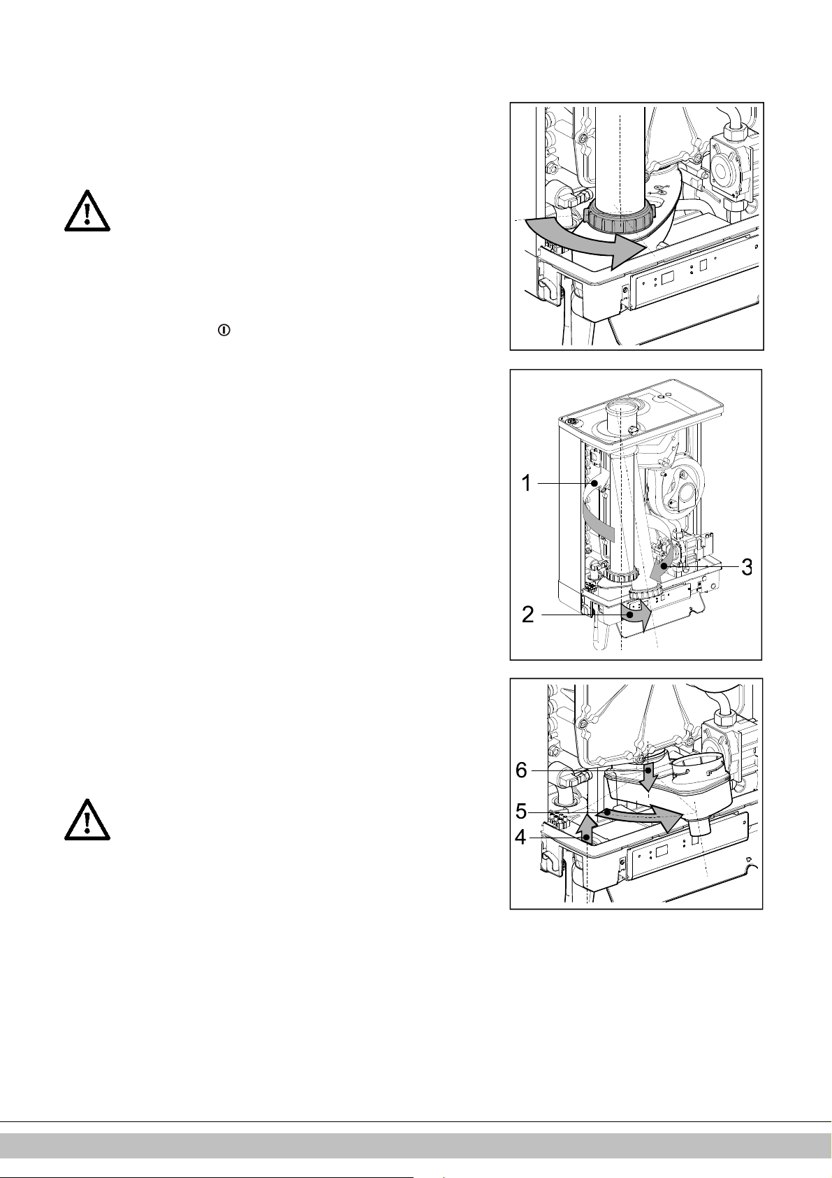
9 MAINTENANCE
The unit and the installation must be checked by a certified installer, and cleaned if
necessary.
CAUTION
Work on gas carrying parts may only be carried out by a
certified installer.
After work, check the flue gas carrying parts for air tightness.
If the unit has just been operational, some parts may be hot.
9.1.1 Disassembly
1. Switch the unit off with the button.
2. Remove the plug from the socket.
3. Shut the gas valve.
4. Open the display valve and loosen the two screws on the left and right of the display,
and remove the front panel.
5. Wait until the unit has cooled down.
6. Unscrew the coupling nut at the bottom of the flue tube to the left.
7. Slide the flue gas pipe upwards (1) with a turn to the left until the bottom of the pipe
reaches above the coupling of the condense outlet container. Pull the bottom of the
pipe forward (2) and remove the pipe by rotating it to the left and down (3)..
8. Lift the condense outlet tray from the connection of the siphon (4) on the left, and
turn it to the right with the siphon connection over the edge of the bottom tray (5).
Push down the condense outlet tray at the back from the connection to the heat
exchanger (6) and remove it from the unit.
9. Take the connector from the fan and the ignition unit from the gas block.
10. Disconnect the coupling under the gas block.
11. Unscrew the shouldered bolts (hex key) of the front lid and remove it to the front,
complete with gas block and fan (be careful not to damage the boiler controller,
insulation plate, gas block, gas pipe and fan). Lay the removed front lid with the foot
rests horizontally on a flat surface.
12. The boiler controller and the integrated insulation plate do not require any
maintenance (do not need cleaning). Therefore never use a brush or compressed air
to clean these parts, in order to avoid dust developing.
13.
9.1.2 Cleaning
1. Clean the bottom of the heat exchanger.
2. Clean the condense outlet tray with water.
3. Clean the siphon with water.
4. Only clean the bottom of the front plate.
CAUTION
The integrated insulation plate and boiler controller gasket
contain ceramic fibers.
Daikin Europe NV
48
Page 48
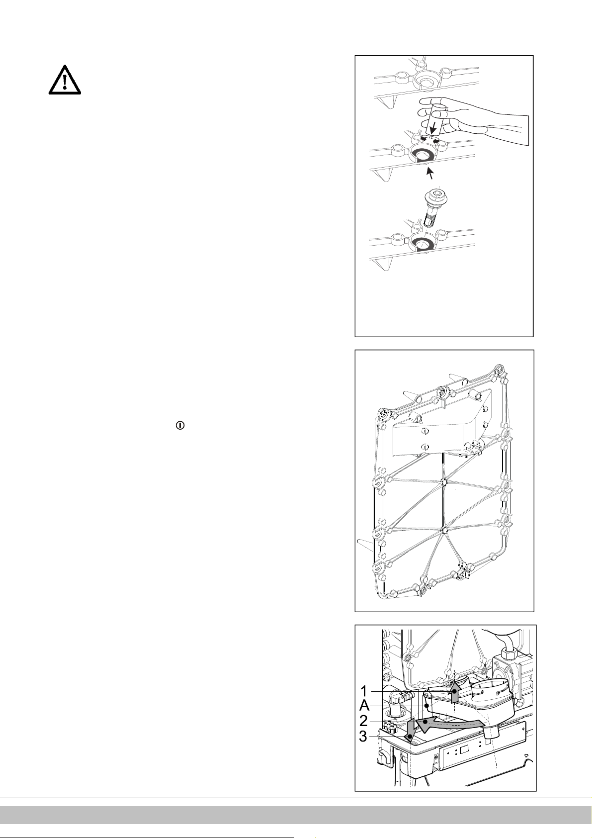
9.1.3 Fitting
03010078
03010083
1
2
3
4
5
6
7
8
9
10
11
During maintenance the seal front plate needs to be replaced.
When assembling, check the other seals for damages,
hardening, (hairline) fractures and/or discoloration. Where
necessary, place a new seal. Also check the correct positioning.
1. Check that between the flange of the shoulder bolt and the front plate,
there is a thin layer of ceramic grease.
If there is no or insufficient grease, it must be applied (see image).
2. Check whether the seal around the front plate has been fitted correctly.
Place the front plate on the heat exchanger and secure it with the special
shoulder bolts (Allen bolts). Evenly tighten the shoulder bolts crosswise
manually (10 – 12 Nm). For the sequence of tightening, see image.
Please note: The front plate in the image has 11 shoulder bolts
The front plate of the EHOBG12ABV1 and EHOBG18ABV1 has 9 shoulder
bolts.
3. Evenly manually tighten the boiler controller bolts crosswise.
4. Fit the gas coupling under the gas block.
5. Fit the connector onto the fan and the ignition unit onto the gas block.
6. Fit the condense outlet tray by sliding it into the outlet stump of the switcher
(1), with the siphon connection, before the bottom tray. Then turn the
condense outlet tray to the left (2) and push it down into the siphon
connection (3). Make sure that the rear of the condense outlet tray ends up
resting on the cam at the back of the bottom container (A).
7. Fill the siphon with water and fit it onto the connection under the condense
outlet tray.
8. Slide the flue gas pipe, while turning it to the left, with its top around the flue
gas adapter in the top lid.. Insert the bottom into the condense outlet tray,
drag the gasket down and tighten the swivel head to the right.
9. Open the gas valve and check the gas couplings under the gas block and on
the assembly bracket for leakage.
10. Check the CH and the water pipes for leakage.
11. Insert the plug into the socket.
12. Switch the unit on with the button.
13. Check the front lid, the connection of the fan to the front lid and the flue tube
parts for leaks.
14. Check the gas-air regulation (see par. 7.7 ) and check the gas coupling on
the gas block for gas tightness.
15. Assemble the cover and tighten the two screws to the left and the right of the
display, and close the display cover.
16. Check the heating and the hot water provision for correct functioning.
49
Daikin Europe NV
Page 49

10 TECHNICAL SPECIFICATIONS
Model name EHOBG12ABV1 EHOBG18ABV1
Condensing boiler Yes Yes
Low temperature boiler No No
B1 boiler No No
Combination heater No No
CH
Nom. load upper value, Qn (Hs) kW 4,2 – 13,9 6,2 – 20,8
Nom. load lower value, Qn (Hi) kW 3,8 – 12,5 5,6 – 18,7
Nom. Power, Pn kW 4,1 –12,2 6,1 – 18,2
Max. CH water pressure, PMS bar 3
Max. CH water temperature °C 90
Other data
Gas consumption G25
Gas consumption G20
Gas consumption G31
Pressure loss of the unit (CH) mH20 See par. 7.4
Max. Flue gas temperature °C 70 70
Mass.flow flue gas (max) g/s 5,8 8,7
Available fan pressure Pa 75 75
NOx class 6 6
NOx mg/kWh 19 38
P1 at 30% of rated input (30/37) kW 4,1 6,1
P4 at rated output (80/60) kW 12,2 18,2
ɳ 1, Efficiency at P1
ɳ 4, Efficiency at P4
Standby heat loss (Pstby)
Electrical data
Mains voltage V 230
Safety class IP IPX4D (B23, B33 = IP20)
Absorbed power: full load W 80
Absorbed power: standby W 2
Auxiliary electricity consumption at full load (elmax) kW 0,040 0,035
Auxiliary electricity consumption at part load (elmin) kW 0,015 0,015
Auxiliary electricity consumption in stand by mode (Pstby) kW 0,002 0,002
Installation measurements and weight
Height mm 590
Width mm 450
Depth mm 240
Weight kg 30
Gas category
Destionation country Boiler categorie (EN437) Gas type and gas inlet pressure (EN 437)
IT II2H3P G20, 20 mbar, G31: 37 mbar
FR II2Esi3P G20, 20 mbar, G31: 37 mbar
BE I2E(S) G20, 20 mbar, G25: 25 mbar
PL II2E3P G20, 20 mbar, G31: 37 mbar
DE II2ELL3P G20, 20 mbar, G25: 20 mbar, G31: 50 mbar
(1)
G20 – Natural gas E/H
G25 – Natural gas LL/L
G31 – Liquefied Propane gas
(1)
m3/h 0.42 – 1.50 0.67 – 2.25
(1)
m3/h 0.36 – 1.30 0.58 – 1.94
(1)
m3/h 0.14 – 0.49 0.22 – 0.74
% 98,1 97.3
% 87,9 87,7
kW 0,037 0,037
(1)
(EN 15502) B23; B33; C13x; C33x; C43x; C53x; C63x; C83x: C93x
Daikin Europe NV
50
Page 50
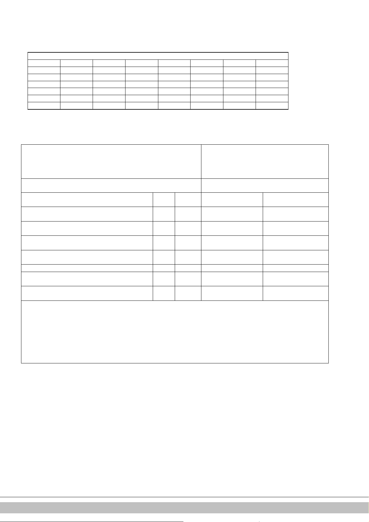
10.1 NTC resistances
NTC 12k Ohm
T [°C] R [ohm] T [°C] R [ohm] T [°C] R [ohm] T [°C] R [ohm]
-15 76020 15 18300 45 5522 75 1994
-10 58880 20 14770 50 4609 80 1717
-5 45950 25 12000 55 3863 85 1467
0 36130 30 9805 60 3253 90 1266
5 28600 35 8055 65 2752 95 1096
10 22800 40 6653 70 2337 100 952
10.2 Technical Product Fiche in accordance to CELEX-32013R0811
Product datasheet
Supplier
Type designation
Seasonal space heating energy efficiency class - - A A
Daikin Europe NV
Zandvoordestraat 300
8400 Oostende
Belgium
EHOBG12ABV1 EHOBG18ABV1
Heat rated output
Seasonal space heating energy efficiency ηS % 92 92
Annual energy consumption QHE GJ 25 37
Sound power level LWA dB 50 45
Efficiency class integrated controller II II
Contribution to yearly efficiency % 2,0 2,0
IMPORTANT
• Please read all instructions before fitting this appliance.
• This appliance is not intended for use of persons (including children) with diminished physical, sensory or mental ability, or lack of
experience and knowledge, unless supervised by, or instruction about the use of the appliance by a person who is responsible for their
safety.
• The appliance and installation should every year be inspected by an qualified installer and cleaned when necessary.
• The appliance can be cleaned with a damp cloth. Don’t use aggressive or abrasive cleaning- or solvent
P
rated
kW 12 18
Daikin Europe NV
51
Page 51

10.3 Electrical diagram
A
Earth connection exchanger
Ignition hood
B
Boiler controller
C
E
Earth connections
F
Fuse (3.15 A T)
Gas block + ignition module
G
Ignition/ionization pin
I
M
Mains electricity supply
P1
CH pump
Resistance
R
Leaving water sensor
S1
S2
Return sensor
S7
CH water pressure sensor
Fan
V
Connector X4
24V=
8-9
9-10
11-12
Connector X2
230V
~
7-8
3-5-6
Connector X5
5 -
6-7
2-4
PWM control CH-pump. (5= PWM signal (red), E=earth)
On/off room thermostat
Outdoor sensor
Tank sensor
(12 kOhm / 25°C)
OpenTherm room thermostat
Mains supply 230 V (2 = L (brown), 4 = N (blue))
CH pump
(8 = L (brown), 7 = N (blue))
Three-way valve for external tank
(e.g. EK3WV1AA)
(0.1A-24Vdc) and/or frost thermostat
(12 kOhm / 25°C)
(6-7 should be open)
(3 = L (brown), 5 = Switch (black), 6 = N (blue))
Computer interface
Daikin Europe NV
52
Page 52

11 WARRANTY CONDITIONS
If the unit
is due for replacement, it can usually be taken
The general warranty conditions of Daikin Europe NV apply to
this product.
The warranty is void if it is determined that the faults,
damages, or undue wear are attributable to improper use or
inexpert treatment or inexpert repair, setting, installation or
maintenance, by non-certified installers, or that it was exposed to
substances with aggressive chemicals (incl. hair spray) and other
damaging substances.
The warranty also becomes void when pipes and couplings have
been applied in the installation which may cause oxygen diffusion,
or the defect is a consequence of lime scale (damaging to the unit
and installation). Surface damage as well as transport damage is
included under the warranty. The entitlement to warranty becomes
void if it cannot be proven that the CH boiler has been subjected to
maintenance by a certified installer at least once a year from the
commissioning date. The instructions for installation and use which
we provide for units must be followed in full.
Use as intended
The unit, as described in this documentation is intended for heating
spaces via a central heating installation and/or the supply of hot water.
Any other usage falls outside the intended use of the unit. No liability
can be accepted on damage arising from incorrect use.
Environment
back by your dealer, following consultation. Should this not
be possible, consult your council for the possibilities for
recycling or environmentally friendly processing of used
materials.
Various plastics and metals were used in the manufacturing
of the unit. Furthermore, the unit contains electrical
components which belong with electronic waste.
Use as intended
The unit, as described in this documentation is intended for heating
spaces via a central heating installation and/or the supply of hot water.
Any other usage falls outside the intended use of the unit. No liability
can be accepted on damage arising from incorrect use.
Daikin Europe NV
53
Page 53

INHALTSVERZEICHNIS
1
2
3
4
5
6
7
8
9
10
11
Sicherheitshinweise 5
Gerätebeschreibung 6
2.1 Allgemeines ..................................................................................................................................................................................... 6
2.2 Funktionsweise ................................................................................................................................................................................ 6
2.3 Betriebsarten ................................................................................................................................................................................... 6
2.4 PC-Bedienoberfläche ...................................................................................................................................................................... 8
2.5 Testprogramme ............................................................................................................................................................................... 8
Hauptkomponenten 9
3.1 Zubehör ......................................................................................................................................................................................... 10
Installation 11
4.1 Abmessungen der Anlage ............................................................................................................................................................. 11
4.2 Installationsort ............................................................................................................................................................................... 13
4.3 Montage ........................................................................................................................................................................................ 14
Anschließen 16
5.1 Anschließen der ZH-Installation .................................................................................................................................................... 16
5.2 Elektronischer Anschluss .............................................................................................................................................................. 18
5.3 Anschließen des Raumthermostats .............................................................................................................................................. 19
5.4 Anschließen der Gasleitung .......................................................................................................................................................... 20
5.5 Abzug- und Luftzufuhrkanal .......................................................................................................................................................... 21
5.6 Auslasssysteme ............................................................................................................................................................................ 22
5.7 Abzugsmaterial .............................................................................................................................................................................. 23
5.8 Anschluss an eine Abgasanlage ohne Lufteinlass (B23, B33) ...................................................................................................... 25
5.9 Anschluss an eine abgedichtete Abgasanlage. ............................................................................................................................ 26
Inbetriebnahme des Geräts und der Installation 34
6.1 Befüllen und Entlüften des Geräts und der Installation ................................................................................................................. 34
6.2 Inbetriebnahme der Einheit ........................................................................................................................................................... 35
6.3 Ausschalten des Geräts ................................................................................................................................................................ 36
Einstellungen und Anpassungen 37
7.1 Direkt über das Bedienteil ............................................................................................................................................................. 37
7.2 Parametereinstellungen über den Wartungscode ......................................................................................................................... 38
7.3 Einstellung der maximalen ZH-Leistung........................................................................................................................................ 40
7.4 Festlegung der Pumpeneinstellungen ........................................................................................................................................... 40
7.5 Witterungsgeführte Regelung........................................................................................................................................................ 40
7.6 Wechsel zu einem anderen Gastyp .............................................................................................................................................. 41
7.7 Gas/Luft-Regelung ........................................................................................................................................................................ 41
7.8 Einstellen der Gas/Luft-Regelung ................................................................................................................................................. 42
Störungen 44
8.1 Anzeigen der letzten Störung ........................................................................................................................................................ 44
8.2 Störungscodes .............................................................................................................................................................................. 44
8.3 Sonstige Störungen ....................................................................................................................................................................... 45
Wartung 48
Technische Daten 50
10.1 TC-Widerstand .............................................................................................................................................................................. 50
10.2 ERP Daten gemäß CELEX-32013R0811, Annex IV ..................................................................................................................... 51
10.3 Schaltplan ...................................................................................................................................................................................... 52
Gewährleistungsbedingungen 53
© 2019 Daikin Europe NV
Alle Rechte vorbehalten.
Die aufgeführten Informationen beziehen sich auf das Produkt in seiner Standardversion. Die Daikin Europe NV kann daher nicht für Schäden haftbar gemacht
werden, die sich aus jeglichen von der Standardversion abweichenden Spezifikationen des Produkts ergeben. Die vorliegenden Informationen wurden mit
größtmöglicher Sorgfalt zusammengestellt. Die Daikin Europe NV kann jedoch nicht für fehlerhafte Informationen oder für sich hieraus ergebende Folgen haftbar
gemacht werden. Die Daikin Europe NV kann nicht haftbar gemacht werden für Schäden, die sich aus den von Dritten durchgeführten Arbeiten ergeben.
Änderungen vorbehalten.
Daikin Europe NV
3
Page 54

Diese Installationsanleitung
Mit dieser Installationsanleitung können sich das Gerät auf sichere Weise
zusammenbauen, installieren und warten. Befolgen Sie die Anweisungen sorgfältig.
Wenden Sie sich im Zweifelsfall an den Hersteller.
Bewahren Sie die Installationsanleitung in der Nähe des Geräts auf.
Verwendete Abkürzungen und Begriffe
Beschreibung Bezeichnet als
Daikin EHOBG12ABV1, EHOBG18ABV1 Gerät
Gerät mit Rohrleitungen für Zentralheizung ZH-Installation
System mit Rohrleitungen für Warmwasser BW-Installation
Symbole
Die folgenden Symbole werden in dieser Anleitung verwendet:
VORSICHT
Verfahren die - falls nicht mit der notwendigen Sorgfalt
ausgeführt - zu Schäden am Produkt, der Umgebung, der
Umwelt oder zu Personenschäden führen können.
WICHTIG
Verfahren und/oder Anweisungen, die - falls nicht befolgt -
negative Auswirkungen auf die Funktionsweise des Geräts
haben werden.
Daikin Europe NV
4
Page 55

Service und technischer Support für den Monteur
Informationen zu spezifischen Einstellungen, zur Installation, Wartung und zu
Reparaturarbeiten erhalten Sie - als Monteur - bei Ihrem lokalen Daikin-Händler.
Identifikation des Produkts
Die Gerätedetails sind auf dem Typschild unten am Gerät aufgeführt.
Das Typenschild enthält, neben der Lieferanteninformation und der Kesselspezifikation
(Kesseltyp und Modellname), folgende Informationen:
******-yymm****** Artikelnummer, Seriennummer YY = Baujahr, mm = Monat der
Produktion
PIN Produktidentifikationsnummer
Daten zur Heizung
Informationen zur Stromversorgung
Spannung, Netzfrequenz, elmax, IP-Klasse)
PMS Zulässiger Höchstdruck im Heizungskreis (in bar)
Qn HS Die Eingabe bezieht sich auf den Brennwert in Kilowatt
Qn Hi Eingabe bezogen auf den Heizwert in Kilowatt
Pn Leistung in Kilowatt
BE, DE, FR, IT, PL Bestimmungsländer (EN 437)
I2E(s), I2H,
IIELL3P, II2H3P,
II2Esi3P
G20-20 mbar
G25-25 mbar
B23, …. C93(x) Zugelassene Abgasklassen (EN 15502)
Zugelassene Gerätekategorien (EN 437)
Werkseitig eingestellte(r) Gasgruppe und Gasanschlussdruck
(EN 437)
Tmax Max. Vorlauftemperatur in ° C
IPX4D Elektrische Schutzart
1 SICHERHEITSHINWEISE
Der Hersteller Daikin Europe NV haftet nicht für Schäden oder Verletzungen, die sich aus der
Nichtbeachtung der Sicherheitshinweise oder aus Nachlässigkeiten während der Installation
des wandmontierten Gasheizkessels Daikin EHOBG*ABV1 und jeglichen zugehörigen
Zubehörteilen ergeben.
Dieses Gerät ist nicht konzipiert, um von folgenden Personengruppen einschließlich Kindern
benutzt zu werden: Personen mit eingeschränkten körperlichen, sensorischen oder geistigen
Fähigkeiten oder Personen mit mangelhafter Erfahrung oder Wissen, es sei denn, sie sind von
einer Person, die für ihre Sicherheit verantwortlich ist, darin unterwiesen worden, wie das Gerät
ordnungsgemäß zu verwenden und zu bedienen ist.
Die gesamte Installation muss den geltenden lokalen technischen und sicherheitstechnischen
Vorschriften sowohl im Hinblick auf die Gasinstallation, die elektrische Installation, die
Rauchabzugsinstallation, die Trinkwasserinstallation als auch die Zentralheizungsinstallation
entsprechen.
WICHTIG
Dieses Produkt ist nur zur Verwendung in Gebäuden
vorgesehen.
Daikin Europe NV
5
Page 56

2 GERÄTEBESCHREIBUNG
2.1 Allgemeines
Der wandmontierte Gasheizkessel Daikin EHOBG*ABV1 ist ein geschlossenes Gerät.
Das Gerät dient dazu, Wasser einer ZH-Installation sowie BW-Installation zu erwärmen.
Die Luftzufuhr und die Brenngasabfuhr können mittels zwei separater Rohrleitungen an
das Gerät angeschlossen werden. Auf Verlangen ist ein konzentrischer Anschluss
lieferbar. Das Gerät wurde in Kombination mit der Kombi-Durchführung getestet, aber
es kann auch an Kombi-Durchführungen angeschlossen werden, die den universalen
Teststandards für Kombi-Durchführungen entsprechen.
Das Gerät kann bei Bedarf an einen Montagehalter, einen Rahmen mit oberem
Anschluss und verschiedene Installationssets angeschlossen werden. Diese sind
separat erhältlich.
Die wandmontierten Gasheizkessel Daikin EHOBG*ABV1 sind CE-zertifiziert und
entsprechen der Schutzart IP44.
Das Gerät wird standardmäßig für Erdgas (G20) geliefert. Ein Umbauset für Propangas
(G31) ist auf Anfrage erhältlich.
2.2 Funktionsweise
Der wandmontierte Gasheizkessel Daikin EHOBG*ABV1 ist ein aussteuernder Kessel
mit einem hohen Wirkungsgrad. Das bedeutet, dass die Leistung moduliert wird, um
der jeweiligen Heizanforderung optimal zu entsprechen.
Eine Kupfer-ZH-Kreislauf ist in den Aluminium-Wärmetauscher integriert.
Das Wasser in der BW-Installation kann durch Anschluss des Geräts an einen indirekt
geheizten Speichers mittels eines 3-Wege-Ventils und eines Speicherfühlers erwärmt
werden (siehe Abschnitt 5.1 und 5.2). Die integrierte Speicherregelung des Geräts
gewährleistet, dass die Warmwasserbereitung Vorrang vor dem Heizen hat. Beide
Betriebsarten können gleichzeitig ausgewählt sein.
Das Gerät ist mit einer elektronischen Kesselsteuerung ausgestattet, der den Lüfter bei
jeder Heizanforderung der Heizung oder der Warmwasserversorgung betreibt, das
Gasventil öffnet, die die Kesselsteuerung zündet und die Flamme abhängig von der
angeforderten Leistung kontinuierlich überwacht und regelt.
2.3 Betriebsarten
Die Betriebsart des Geräts wird mittels eines Codes an der Wartungsanzeige des
Bedienteils angezeigt.
-
Aus
Das Gerät ist nicht in Betrieb, aber an die Stromversorgung angeschlossen. Auf
Warmwasseranforderungen oder Heizanforderungen der Zentralheizung erfolgt keine
Reaktion. Der Frostschutz des Geräts ist aktiv. Das bedeutet, dass die Pumpe ihren
Betrieb aufnimmt und der Wärmetauscher aufgeheizt wird, wenn die Temperatur des
Wassers im System zu tief sinkt.
Wenn der Frostschutz aktiviert ist, wird der Code
Wärmetauschers).
Der Druck in der ZH-Installation kann in dieser Betriebsart auch auf der
Temperaturanzeige abgelesen werden (in Bar).
Standby
Die LED an der Taste und wahrscheinlich auch eine der LEDs für die WarmwasserKomfortfunktion leuchten. Das Gerät ist bereit, auf Anforderungen der Zentralheizung
oder Warmwasseranforderungen zu reagieren.
7
angezeigt (Aufheizen des
0
ZH-Nachlauf
Nach Beendigung des ZH-Betriebs läuft die Pumpe noch für den angegebenen
Zeitraum weiter. Die Pumpennachlaufzeit ist auf den in Abschnitt 7.2 aufgeführte
werkseitig eingestellten Wert gesetzt. Diese Einstellung ist änderbar. Darüber hinaus
wird die Pumpe automatisch 1 Mal alle 24 Stunden für 10 Sekunden betrieben, um
Verstopfungen zu vermeiden. Diese automatische Einschaltung der Pumpe erfolgt zum
Zeitpunkt der letzten Heizanforderung. Um diese Einstellung zu ändern, muss das
Raumthermostat zur gewünschten Tageszeit für einen Moment höher eingestellt
werden.
1
Soll-Temperatur erreicht
Die Kesselsteuerung kann die Heizanforderung temporär blockieren. Die
Kesselsteuerung wird dann gestoppt. Die Blockierung erfolgt, weil die erforderliche
Daikin Europe NV
6
Page 57

Temperatur erreicht ist. Wenn die Temperatur ausreichend gefallen ist, wird die
Blockierung aufgehoben.
2
Selbsttest
Einmal alle 24 Stunden testet die Kesselsteuerung die angeschlossenen Fühler.
Während des Tests führt der Brennerautomat keine anderen Aufgaben aus.
3
Lüftung
Wenn das Gerät gestartet wird, wird der Lüfter zunächst auf seine korrekte
Startumdrehungszahl gebracht. Wenn die Startumdrehungszahl erreicht ist, wird die
Kesselsteuerung gezündet. Der Code
Kesselsteuerung ein Lüfternachlauf erfolgt.
4
Zündung
Wenn der Lüfter die Startdrehzahl erreicht hat, wird der Brennerautomat durch
elektrische Funken gezündet. Während der Zündung wird der Code
Wenn die Kesselsteuerung beim ersten Versuch nicht gezündet wird, erfolgt nach
15 Sekunden ein neuer Zündversuch. Wenn die Kesselsteuerung nach 4
Zündversuchen immer noch nicht gezündet wurde, geht die Kesselsteuerung in den
Störungsmodus über.
5
ZH-Betrieb
Ein Ein/Aus-Thermostat, ein OpenTherm-Thermostat, ein Außentemperaturfühler oder
eine Kombination dieser Thermostate/Fühler kann an die Kesselsteuerung
angeschlossen werden (siehe Abschnitt 10.3).
Wenn eine Heizanforderung von einem Thermostat anliegt, nachdem der Lüfterbetrieb
gestartet wurde (Code
das Gerät in den ZH-Betrieb über (Code
Während des ZH-Betriebs kann die Drehzahl des Lüfters und somit die Leistung des
Geräts angepasst werden, um so die Wassertemperatur der Zentralheizung gemäß der
ZH-Solltemperatur zu regeln. Wenn ein Ein/Aus-Thermostat angeschlossen ist, ist dies
die an der Anzeige eingestellte ZH-Solltemperatur. Falls ein OpenTherm-Thermostat
angeschlossen ist, wird die ZH-Solltemperatur vom Thermostat bestimmt. Falls ein
Außentemperaturfühler angeschlossen ist, wird die ZH-Solltemperatur von der in der
Kesselsteuerung programmierten Heizkurve bestimmt. In den beiden letztgenannten
Fällen ist die an der Anzeige eingestellte Temperatur die Höchsttemperatur.
Während des ZH-Betriebs wird die ZH-Solltemperatur am Bedienteil angezeigt.
Die ZH-Solltemperatur kann zwischen 30 und 90°C eingestellt werden (siehe Abschnitt
7.1). Vorsicht: Für ein Niedertemperatursystem ist möglicherweise eine niedrigere
Höchsttemperatureinstellung als die Standardeinstellung von 80°C erforderlich.
Sie können während des ZH-Betriebs die Wartungstaste drücken, um die tatsächliche
ZH-Solltemperatur abzulesen.
3
), erfolgt zunächst die Zündung (Code
3
wird angezeigt, wenn nach dem Stopp der
4
angezeigt.
4
), und dann geht
5
).
Wenn die Warmwasser-Komfortfunktion eingeschaltet ist (siehe Code
OpenTherm-Heizanforderung von weniger als 40 Grad generiert.
7
), wird eine
Daikin Europe NV
7
Page 58

6
•
angezeigt (Aufheizen des
Warmwasserbetrieb
EHOBG*ABV1 in Kombination mit einem indirekt befeuerten Speicher
Die Warmwasserversorgung hat Vorrang vor dem Heizbetrieb. Wenn ein Speicherfühler
verwendet wird, wird jegliche ZH-Anforderung unterbrochen, wenn der Speicherfühler
eine Temperatur von 5 Grad unter dem Sollwert erkennt. Nachdem der Lüfterbetrieb
gestartet wurde (Code
Kesselsteuerung in den Warmwasserbetrieb (Code
verwendet wird, startet die Heizanforderung, wenn das Thermostat geöffnet wird, und
stoppt, wenn das Thermostat wieder schließt. Die Lüftergeschwindigkeit und somit die
Leistung des Geräts wird in diesem Fall auf der Grundlage einer festen
Vorlauftemperatur durch die Kesselsteuerung geregelt. Die Warmwassertemperatur
kann zwischen 40°C und 65°C eingestellt werden. Während des Warmwasserbetriebs
wird die eingestellte Speichertemperatur am Bedienfeld angezeigt. Sie können während
des Warmwasserbetriebs die Wartungstaste drücken, um die tatsächliche
Speichertemperatur abzulesen.
3
) und die Zündung erfolgt ist (Code
6
4
) schaltet die
). Wenn ein Speicherthermostat
2.4 PC-Bedienoberfläche
Die Kesselsteuerung ist mit einer Bedienoberfläche für einen PC ausgestattet. Ein PC
kann mittels eines Dongles und der zugehörigen Software angeschlossen werden.
Diese Funktion ermöglicht Ihnen, das Verhalten der Kesselsteuerung, des Geräts und
der Heizinstallation über einen längeren Zeitraum zu verfolgen.
2.5 Testprogramme
Der Brennerautomat verfügt über eine Option, um das Gerät in einen Testmodus zu
versetzen.
Die Aktivierung eines Testprogramms führt zur Einschaltung des Geräts mit einer
festgelegten Lüfterdrehzahl pro Minute, die nicht durch die Regelungsfunktionen
verändert werden kann.
Die Sicherheitsfunktionen bleiben aktiv.
Das Testprogramm wird durch gleichzeitige Betätigung von und beendet.
Testprogramme
Beschreibung des Programms Tastenkombination Displayanzeige
Brenner ein mit minimaler BWLeistung (siehe Parameter d,
Abschnitt 7.2)
Brenner ein mit eingestellter
maximaler ZH-Leistung (siehe
Parameter 3, Abschnitt 7.2)
Brenner ein mit eingestellter
maximaler BW-Leistung (siehe
Parameter 3, Abschnitt 7.2)
Ausschaltung des Testprogramms und
Während der Testmodus können folgende Daten gelesen werden:
• Durch Drücken der Taste kontinuierlich im Display die CH Wasserdruck wird angezeigt.
• Durch Drücken der Taste ständig in der Anzeige der Ionisationsstrom gezeigt.
und "L"
und (1x)
und (2x)
Betriebssituation
"h"
"H"
Aktuelle
2.5.1 Frostschutz
Hinweis
Wenn das Gerät ausgeschaltet ist ( - in der Wartungsanzeige), bleibt die
Frostschutzfunktion des Geräts aktiv. Eine Aufwärmanforderung von einem (externen)
Frostschutzthermostat wird jedoch ignoriert.
Daikin Europe NV
Das Gerät mit einer Frostschutzfunktion ausgestattet, um ein
Einfrieren des Geräts zu verhindern. Wenn die Temperatur des
Wärmetauschers zu tief sinkt, wird der Pumpenbetrieb gestartet, bis
die Temperatur des Wärmetauschers hoch genug ist. Wenn der
Frostschutz aktiviert ist, wird der Code
Wärmetauschers).
• Wenn die Installation (oder ein Teil hiervon) einfrieren kann, sollte
die kälteste Stelle mit einem (externen) Frostschutzthermostat an
der Rückleitung ausgestattet werden. Dieses muss gemäß dem
Schaltplan angeschlossen werden (siehe Abschnitt 10.3).
7
8
Page 59

3 HAUPTKOMPONENTEN
Zünd-/Ionisierungsstift
0207010009
A. Modulierende ZH-Pumpe K. Konzentrischer Rauchgas/Luftzufuhr-Adapter
B. Gasventil L. Luftzufuhr (nur bei Verwendung des DoppelrohrC. Kesselsteuerung (inkl. Bedienteil)
Rauchabzugssystems)
D. Fühler S1 (Fluss) M. Anschlussblock/Anschlussleiste X4
E. Fühler S2 (Rücklauf) N. Kondensatkollektor
F. Lüfter O. Siphon
G. Drucksensor Zentralheizung P. Wärmetauscher
H. 230 V-Anschlusskabel mit geerdetem Stecker Q. Bedienteil und Anzeige
I. Manuelle Entlüftung R.
J. Schauglas S. Position der Datenplatte
Daikin Europe NV
9
Page 60

3.1 Zubehör
Beschreibung Artikelnummer
B-Pack klein EKFJS*AA
B-Pack mittel EKFJM*AA
B-Pack groß EKFJL*AA
Ventil-Kit EKVK4AA
Abdeckplatte EKCP1AA
Außentemperaturfühler EKOSK1AA
3-Wege-Ventilsatz EK3WV1AA
Verbrennungsgasadapter, konzentrisch Ø80x125 EKHY090717
Verbrennungsgasadapter, parallel 80 mm
EKHY090707
Propanumwandlungs-Set EHOBG12ABV1 EKPS075917
Propanumwandlungs-Set EHOBG18ABV1 EKPS075877
Daikin Europe NV
10
Page 61

4 INSTALLATION
A = Zulauf ZH
G ¾” (außen)
B = Rücklauf ZH
G ¾” (außen)
C = Gas G ½” (innen)
D = Kondensatauslass
Ø dn25 (flexibel)
h =
517 mm
EHOBG
12
ABV1
H =
590 mm
EHOBG
12
ABV1
Z = Verbrennungsgasauslass/
Ø60/100 (konzentrisch)
020601005
161
161
450
240
77
135
h
D
130 130
77
4.1 Abmessungen der Anlage
Kessel direkt an der Wand montiert:
Gerät + Montagehalter
EHOBG18ABV1
EHOBG18ABV1
Lufteinlass
Daikin Europe NV
11
Page 62

A = Zulauf ZH
G ¾” (außen)
B = Rücklauf ZH
G ¾” (außen)
C = Gas G ½” (innen)
D = Kondensatauslass
Ø dn25 (flexibel)
H = 770 mm
EHOBG
12
ABV1
Z = Verbrennungsgasauslass/
Ø60/100 (konzentrisch)
020601006
265
265
77
77
D
50
130 130
Gerät angeschlossen an B-Pack:
Gerät + B-Pack
EHOBG18ABV1
Lufteinlass
Daikin Europe NV
12
Page 63

4.2 Installationsort
Das Gerät kann an einer Wand mit ausreichender Tragkraft montiert werden.
Bei leichten Wandkonstruktionen besteht die Gefahr von Resonanzgeräuschen.
Innerhalb von 1 Meter Entfernung zum Gerät muss sich eine geerdete Netzsteckdose
befinden.
Um das Einfrieren des Kondensatauslasses zu verhindern, muss das Gerät in einem
frostfreien Raum installiert werden. Gewährleisten Sie, dass ein Freiraum von
mindestens 2 cm neben dem Kessel vorhanden ist. Aufgrund der Gefahr des
Gassengens ist kein Freiraum erforderlich.
4.2.1 Installation in einem Küchenschrank
Das Gerät kann zwischen zwei Küchenschränken oder in einem Küchenschrank
installiert werden.
Stellen Sie sicher, dass oben und unten eine ausreichende Belüftung gewährleistet
ist.
Wenn das Gerät in einem Küchenschrank installiert wird, sind Belüftungsöffnungen
von mindestens 50 cm2 erforderlich.
4.2.2 Entfernen des Abdeckblechs und der Frontabdeckung
Für verschiedene Eingriffe am Gerät müssen das Abdeckblech und die
Frontabdeckung vom Gerät entfernt werden, falls diese installiert wurden. Gehen Sie
hierzu wie folgt vor:
• Falls Sie das Abdeckblech (A) verwenden, entfernen Sie es von der Gerätefront.
• Lösen Sie die beiden Schrauben (1) hinter dem Anzeigefenster.
• Ziehen Sie die Unterseite der Frontabdeckung (2) nach vorn.
Gefahr: Verbrennungsgefahr
Bei hohen Vorlaufwassersollwerten für Raumheizung (hoher fester Sollwert oder hoher
witterungsgeführter Sollwert bei niedrigen Umgebungstemperaturen) kann der
Wärmetauscher des Kessels sehr heiß werden, zum Beispiel 70°C.
Achten Sie darauf, dass bei einer Warmwasserentnahme das Wasser anfängliche eine
höhere als die angeforderte Wassertemperatur haben kann.
In diesem Fall wird empfohlen, ein Thermostatventil zu installieren, um Verbrühungen zu
verhindern.
Gehen Sie dabei nach dem folgenden Schema vor.
a=Kessel, b=BW vom Kessel, c= Kaltwassereinlass,
d=Dusche, e=Thermostatventil (bauseitig zu liefern)
Daikin Europe NV
13
Page 64

4.3 Montage
020601020
Der Kessel kann folgendermaßen an der Wand angehangen werden:
• mittels der Wandaufhängeleiste und dem Anschlusskit EKVK4AA
• mittels eines B-Packs einschließlich Ausdehnungsgefäß und eines Anschluss-
Bausatzes.
4.3.1 Montage der Aufhängeleiste und des Montagehalters
• Stellen Sie sicher, dass die Wandkonstruktion für die Aufhängung des
Kessels geeignet ist.
• Bohren Sie die Löcher für die Aufhängeleiste und den Anschluss-Bausatz
mit Hilfe der mit dem Kessel mitgelieferten Bohrschablone.
• Montieren Sie die Aufhängeleiste und den Montagehalter horizontal an der
Wand mittels der zugehörigen Befestigungsmaterialien.
• Der Kessel kann jetzt an der Aufhängeleiste montiert werden, indem
gleichzeitig die Rohre des Kessels in die Ventile im Montagehalter
eingeschoben werden.
4.3.2 Montage des B-Packs
• Stellen Sie sicher, dass die Wandkonstruktion für die Aufhängung des
Kessels und des B-Packs geeignet ist.
• Bohren Sie die Löcher für den B-Pack-Bausatz mit Hilfe der mit dem
Kessel mitgelieferten Bohrschablone.
• Montieren Sie den B-Pack mittels der zugehörigen Befestigungsmaterialien
an der Wand.
• Bringen Sie den Montagehalter wie in dem im Lieferumfang des B-Packs
enthaltenen Handbuch beschrieben am Rahmen an.
• Schließen Sie den flexiblen Schlauch am Ausdehnungsgefäß und den
Anschluss am Rückschlagventil an. Stellen Sie sicher, dass die
Dichtungsringe eingesetzt sind!
• Der Kessel kann jetzt am B-Pack montiert werden, indem gleichzeitig die
Rohre des Kessels in die Ventile im Montagehalter eingeschoben werden.
Daikin Europe NV
14
Page 65

4.3.3 Montage des Geräts
1. Packen Sie das Gerät aus.
2. Überprüfen Sie den Verpackungsinhalt auf Vollständigkeit:
• Gerät (A)
• Aufhängeleiste (B)
• Siphon + flexibler Schlauch (C)
• Installationsanleitung
• Betriebsanleitung
• Garantiekarte
3. Überprüfen Sie das Gerät auf Beschädigungen: Melden Sie festgestellte
Schäden unmittelbar dem Lieferanten.
4. Installieren Sie die Aufhängeleiste.
5. Überprüfen Sie, ob die Druckringe gerade in den Kupplungen des
Montagehalters positioniert sind.
6. Positionieren Sie das Gerät: Schieben Sie es von oben nach unten über die
Aufhängeleiste (B).
Stellen Sie sicher, dass die Rohrleitungen gleichzeitig in die
Druckringverbindungen gleiten.
7. Ziehen Sie die Druckringverbindungen am Montagehalter fest.
Die Nippel und Rohrleitungen dürfen sich nicht mitdrehen!
8. Öffnen Sie die Anzeigeabdeckung, lösen Sie die beiden Schrauben links und
rechts an der Anzeige und entfernen Sie dann die Frontabdeckung.
9. Montieren Sie den Schlauch (D) am Auslass des Siphons.
Füllen Sie den Siphon mit Wasser und schieben Sie ihn so weit wie möglich auf
den Kondensatauslassanschluss (E) unten am Gerät auf.
10. Dichten Sie den Schlauch (D) des Siphons, falls möglich zusammen mit dem
Überlaufrohr der Einlasskombination und dem Überdruckventil, über die offene
Verbindung (F) im Abwasserrohr ab.
11. Montieren Sie die Luftzufuhr und den Brenngasauslass (siehe Abschnitt 5.5).
12. Montieren Sie die Abdeckung und ziehen Sie die beiden Schrauben links und
rechts an der Anzeige fest. Schließen Sie dann die Anzeigeabdeckung.
4.3.4 Anbringen des Abdeckplatte (optional)
Hängen Sie die umgebaute Oberkante der Abdeckplatte an den Unterlegscheiben an
der Unterseite des Geräts ein und schieben Sie die Abdeckplatte so weit wie möglich
nach hinten.
Hinweis: Wenn Sie den Kessel in Verbindung mit einer Abdeckplatte installieren, ragt
der Siphon unter der Abdeckplatte hervor.
Daikin Europe NV
15
Page 66

5 ANSCHLIEßEN
A
B
020601009
B
A
020601010
5.1 Anschließen der ZH-Installation
1. Spülen Sie die ZH-Installation sorgfältig aus.
2. Bringen Sie das Zuleitungsrohr (A) und das Rückleitungsrohr (B) am AnschlussBausatz an.
3. Alle Rohrleitungen dürfen nur bei ausgeschalteter Stromzufuhr montiert werden,
um elektrische Schläge zu vermeiden.
4. Die vorhandenen Anschlüsse dürfen nicht verdreht werden, um Leckagen zu
vermeiden.
Die ZH-Installation muss ausgestattet werden mit:
• einem Füll-/Ablasshahn (A) in der Rückleitung direkt unterhalb des Geräts.
• einem Ablasshahn am untersten Punkt der Installation.
• einem Überdruckventil (B) von 3 Bar im Zuleitungsrohr in einem Abstand von nicht
mehr als 500 mm vom Gerät.
Zwischen dem Gerät und dem Überdruckventil darf sich kein anderes Ventil und
keine Verengung befinden.
• Ein Ausdehnungsgefäß in der Rückleitung (im B-Pack oder in der Installation).
• einem Rückschlagventil, wenn Rohr nach oben führen, innerhalb kurzer Entfernung
zum Gerät. Dies verhindert das Auftreten eines Thermosiphon-Effekts während der
Betätigung eines Wasserhahns (ein nicht federangetriebenes Rückschlagventil; das
Ventil muss vertikal montiert werden).
5.1.1 Thermostat-Heizkörperhähne
Wenn alle Heizkörper mit Thermostat- oder Kabel-Heizkörperhähnen ausgestattet sind,
muss eine minimale Wasserzirkulation gewährleistet sein. Siehe Abschnitt 7.4.
Daikin Europe NV
16
Page 67
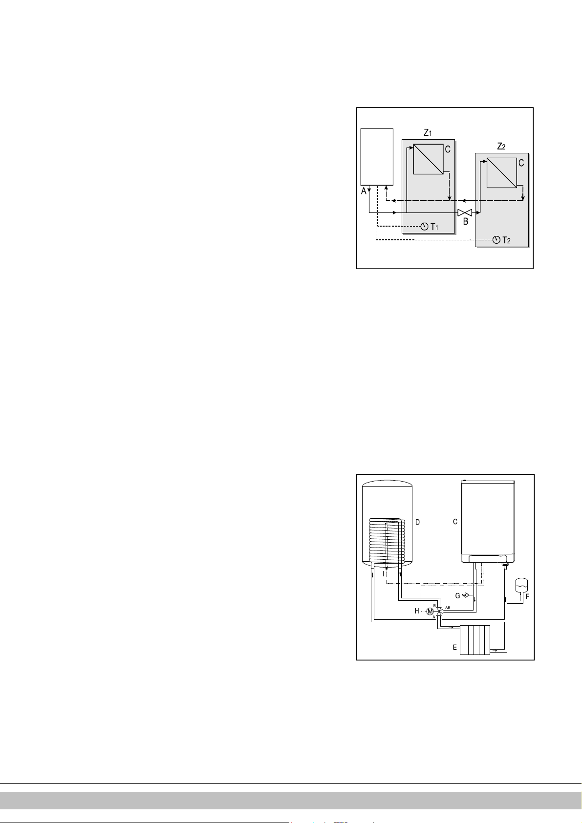
5.1.2 Aufteilen der ZH-Installation in Gruppen bei zusätzlichen
Wärmequellen
Funktionsprinzip
Wenn das Raumthermostat den Kessel ausschaltet, weil der Raum über eine andere
Wärmequelle (Holzofen, offenes Feuer etc.) geheizt wird, können die anderen Räume
abkühlen. Dieses Problem kann durch Aufteilen der ZH-Installation in zwei Zonen
behoben werden. Die Zone mit der externen Wärmequelle (Z2) kann mittels eines
elektrischen Absperrventils vom Hauptkreislauf getrennt werden. Beide Zonen werden
mit ihrem eigenen Raumthermostat ausgestattet.
Hinweis: Die Regelung mit einer "externen Wärmequelle" kann nur angewandt werden,
wenn kein weiterer externer Speicher aufgeheizt werden muss (Installationstyp 1).
Installationsanleitung
1. Installieren Sie das Ventil in Übereinstimmung mit dem Anschlussdiagramm.
2. Schließen Sie das Raumthermostat von Zone 1 an X4 – 6/7 an.
3. Schließen Sie das Raumthermostat von Zone 2 an X4 – 11/12 an.
4. Ändern Sie Parameter A (siehe Parametereinstellungen über den Wartungscode
Abschnitt 7.2).
Hinweis: Das Raumthermostat in Zone
1 MUSS
ein Ein/Aus-Thermostat sein. Das
Raumthermostat in Zone 2 kann ein OpenTherm-Thermostat oder ein Ein/AusThermostat sein.
Anschlussdiagramm für die Regelung "Externe Wärmequelle"
A. Kessel
B. Elektrisches Absperrventil 230 V ~
C. Radiatoren
T1. Raumthermostat Zone 1
T2. Raumthermostat Zone 2
Z1. Zone 1
Z2. Zone 2
Anschließen des externen Speichers
Für den Anschluss des EHOBG*ABV1 an einen indirekt befeuerten Speicher ist ein
Bausatz erhältlich. Dieser Bausatz EK3WV1AA enthält die folgenden Teile und ist auf
Bestellung lieferbar:
• Speicherfühler
• Verriegelungsclip für Speicherfühler
• 3-Wege-Ventil (230 V)
Schließen Sie den Speicher und das 3-Wege-Ventil gemäß dem Plan an. Entfernen Sie
die Durchverdrahtung zwischen 9 und 10 zum Anschluss X4. Schließen Sie das 3Wege-Ventil an Anschluss X2 und den Speicherfühler oder das Kesselthermostat an
Anschluss X4 gemäß dem Anschlussdiagramm an (siehe Abschnitt 10.2).
Anschlussdiagramm für indirekt befeuerten Speicher
C. Gerät
D. Speicher
E. ZH-Installation
F. Ausdehnungsgefäß
G. Sicherheitsventil (3 Bar)
H. 3-Wege-Ventil
I. Speicherfühler oder -thermostat
Hinweis
Wenn ein Ein/Aus-Speicherthermostat verwendet wird, startet die Heizanforderung, wenn
das Thermostat geöffnet wird, und stoppt, wenn das Thermostat wieder schließt.
Bei alten Installationen oder Warmwasserkreisläufen, die kleine Partikel enthalten
können, installieren Sie einen Filter im Warmwasserkreislauf.
Diese Verschmutzungen können während des Warmwasserbetriebs zu Störungen führen.
Daikin Europe NV
17
Page 68

5.2 Elektronischer Anschluss
VORSICHT
Innerhalb von 1 m Entfernung vom Gerät muss sich eine
geerdete Sicherheitssteckdose befinden.
Die Steckdose muss leicht zugänglich sein.
Wenn Sie das Gerät an einem feuchten Ort installieren, ist eine
feste Verbindung mittels eines allpoligen Hauptschalters mit
einem minimalen Kontaktabstand von 3 mm obligatorisch.
Wenn das Stromversorgungskabel beschädigt ist oder aus
einem anderen Grund ersetzt werden muss, muss das ErsatzStromversorgungskabel beim Hersteller oder einem von ihm
zugelassenen Händler bestellt werden. Wenden Sie sich im
Zweifelsfall an den Hersteller oder an einen von ihm
zugelassenen Händler.
1. Ziehen Sie vor jeglichen Arbeiten am Stromkreis den Stecker aus der Steckdose.
2. Falls eine Abdeckplatte (A) vorhanden ist, entfernen Sie es von der Gerätefront.
3. Lösen Sie die beiden Schrauben (1) hinter dem Anzeigefenster.
4. Schieben Sie die Unterseite der Frontabdeckung (2) nach vorn und entfernen Sie
sie.
5. Ziehen Sie die Kesselsteuerung nach vorne. Die Kesselsteuerung kippt bei diesem
Vorgang nach unten.
6. Ziehen Sie den Abschnitt 10.3 zu Rate, um die Anschlüsse vorzunehmen.
7. Nachdem die erforderlichen Anschlüsse vorgenommen wurden, schieben Sie die
Kesselsteuerung wieder in das Gerät und bringen Sie ggf. die Abdeckplatte wieder
an.
8. Nachdem die erforderlichen Anschlüsse vorgenommen wurden, schließen Sie das
Gerät wieder an der geerdeten Steckdose an.
5.2.1 Elektroanschlüsse
Temperaturregelung Anschluss X4 Kommentare
Raumthermostat Ein/Aus 6 - 7 Modulierendes Thermostat
11 - 12
mit Komfortfunktion aktiv
Außentemperaturfühler 8 - 9 Warmwasserspeicherfühler 9 - 10 Gelbe Drahtverbindung
entfernen
Frostschutzthermostat 6 - 7 Parallel über
Raumthermostat
Daikin Europe NV
18
Page 69

5.3
Anschließen des Raumthermostats
5.3.1 Raumthermostat Ein/Aus
1. Schließen Sie das Raumthermostat an (siehe Abschnitt 10.2).
2. Setzen Sie bei Bedarf die Rückkopplungsfestigkeit des Raumthermostats auf 0,1 A.
Messen Sie im Zweifelsfall den elektrischen Strom und stellen Sie den Wert dann
entsprechend ein.
Der maximale Widerstand der Thermostatleitung und des Raumthermostats beträgt
insgesamt 15 Ohm.
5.3.2 Modulierendes Thermostat, Open Therm
Das Gerät ist für den Anschluss eines modulierenden Raumthermostats in
Übereinstimmung mit dem OpenTherm-Kommunikationsprotokoll geeignet.
Die wichtigste Funktion des modulierenden Raumthermostats ist die Berechnung der
Eingangstemperatur für die Soll-Raumtemperatur, um eine optimale Nutzung der
Modulation zu gewährleisten. Bei jeder Heizanforderung wird die erforderliche
Eingangstemperatur an der Anzeige des Geräts angezeigt.
Schließen Sie das modulierende Thermostat an (siehe Abschnitt 10.2).
Wenn Sie die Ein/Aus-Schalter-Funktion des OpenTherm-Thermostats für für
Warmwasser verwenden möchten, muss die Warmwasser-Komfortfunktion auf "Eco"
oder "Ein" eingestellt sein.
Weitere Informationen finden Sie im Handbuch des Raumthermostats.
5.3.3 Modulierendes Funk-Raumthermostat
Der ZH-Kessel EHOBG*ABV1 kann drahtlos ohne Sende-/Empfangsmodul mit den
Honeywell Raumthermostaten T87RF1003 Round RF, DTS92 und CMS927
kommunizieren. Der ZH-Kessel und das Raumthermostat müssen aufeinander
abgestimmt werden:
• Drücken Sie etwa 5 Sekunden lang die Reset-Taste des Geräts, um das Menü
"Funk-Raumthermostat" aufzurufen.
• Einer der folgenden Codes wird an der Anzeige des Geräts angezeigt:
1. rF und L / - : Die Anzeige über der Taste zeigt im Wechsel L und –.
rote LED : blinkend
Der ZH-Kessel und das Raumthermostat wurden nicht aufeinander abgestimmt. Ein
Gerät in diesem Betriebszustand kann mittels der Methode des entsprechenden
Raumthermostats verbunden werden.
Die Methode zur Abstimmung der Geräte aufeinander hängt vom
Raumthermostattyp ab und ist in der Installations- und Bedienungsanleitung des
drahtlosen
Raumthermostats beschrieben.
2. rF und L / 1 : Die Anzeige über der Taste zeigt im Wechsel L und 1
rote LED : aus
Der ZH-Kessel und das Raumthermostat wurden bereits aufeinander abgestimmt.
Es ist bereits eine Verbindung zu einem Funk-Raumthermostat vorhanden. Um
eine neue Verbindung zu erstellen, muss die vorhandene Verbindung entfernt
werden.
Siehe: Aufheben der Zuweisung eines Funk-Raumthermostats zum ZH-Kessel.
• Drücken Sie die Reset-Taste , um das Menü "Funk-Raumthermostat" zu verlassen,
oder warten Sie 1 Minute.
Daikin Europe NV
19
Page 70

Testen der Verbindung zwischen dem Gerät und dem Funk-Raumthermostat
020601011
E
1. Drücken Sie ca. 5 Sekunden lang die Reset-Taste des Geräts, um das
Menü "Funk-Raumthermostat" der Kesselsteuerung aufzurufen.
2. Drücken Sie die Wartungstaste 1x. An der Anzeige über der Taste
wird ein t angezeigt.
3. Versetzen Sie das Raumthermostat in den Testmodus (siehe Installationsund Bedienungsanleitung des Raumthermostats).
4. Die rote LED über der Reset-Taste blinkt, wenn die Gerätezuweisung
korrekt durchgeführt wurde.
5. Drücken Sie die Reset-Taste des Geräts, um das Menü "FunkRaumthermostat" der Kesselsteuerung zu verlassen. Der Testmodus wird
automatisch 1 Minute nach Empfang der letzten Testmeldung des FunkRaumthermostats beendet.
Aufheben der Zuweisung eines Funk-Raumthermostats zum ZH-Kessel.
• Drücken Sie ca. 5 Sekunden lang die Reset-Taste des Geräts, um das
Menü "Funk-Raumthermostat" des ZH-Kessels aufzurufen.
• Drücken Sie die Wartungstaste 2x. An der Anzeige über der
Taste wird ein C angezeigt.
• Drücken Sie die Reset-Taste des Geräts erneut, um die vorhandenen
Zuweisungen aufzuheben. An der Anzeige des Geräts wird wieder rF und
ein blinkendes
L / - angezeigt. Bei Bedarf kann dem Gerät erneut ein Funk-
Raumthermostat zugewiesen werden.
• Drücken Sie die Reset-Taste , um das Menü "Funk-Raumthermostat"
zu verlassen, oder warten Sie 1 Minute.
5.3.4 Außentemperaturfühler
Das Gerät ist mit einer Verbindung für einen Außentemperaturfühler ausgestattet.
Der Außentemperaturfühler sollte in Verbindung mit einem Ein/Aus-Raumthermostat
verwendet werden.
Prinzipiell kann jedes Ein/Aus-Raumthermostat mit einem Außentemperaturfühler
kombiniert werden.
Bei Anforderung durch das Raumthermostat heizt der Kessel, bis die für den Kessel
festgelegte Höchsttemperatur erreicht ist. Diese maximale Solltemperatur wird
automatisch über den Außentemperaturfühler in Übereinstimmung mit der im Kessel
festgelegten Heizkurve reguliert.
Schließen Sie den Außentemperaturfühler an (siehe Abschnitt 10.2).
Informationen zur Einstellung der Heizkurve finden Sie unter "Witterungsgeführte
Regelung" (siehe Abschnitt 7.5).
5.4 Anschließen der Gasleitung
1. Schließen Sie das Gasventil mit einer entsprechenden Dichtugn direkt am 1/2"
Gasanschluss des Anschluss-Bausatzes an.
2. Bringen Sie ein Gassieb in der Leitung zum Gerät an, wenn das Gas
möglicherweise kontaminiert ist.
3. Schließen Sie das Gasrohr mittels einer entsprechenden Dichtung am
Gasventil an.
4. Überprüfen Sie die gasführenden Teile auf Undichtigkeiten bei einem Druck von
bis zu 50 mbar.
5. Die Gasleitung sollte druckfrei montiert werden.
Daikin Europe NV
20
Page 71

5.5 Abzug- und Luftzufuhrkanal
Achten Sie darauf, dass die Rohrstutzen für die Materialien des
und Luftzufuhrkanals ordnungsgemäß abgedichtet sind.
ten, Materialien oder Kupplungen
Zur Verwendung des Materials für den Abzug- und
Luftzufuhrkanal, siehe Handbuch zu den Materialien.
Wenden Sie sich an den
Hersteller der jeweiligen Materialien für den Abzug- und
Luftzufuhrkanal, wenn Sie umfassende technische Angaben
und eine spezifische
Montageanleitung benötigen.
AbzugEine unsachgemäße Befestigung des Abzug- und
Luftzufuhrkanals
kann Gefahren hervorrufen oder zu Verletzungen führen.
Kontrollen Sie alle Komponenten des Abzugssystems auf
Dichtigkeit.
Verwenden Sie für die Montage des Abzugssystems keine
normalen oder selbstschneidenden Parker-Schrauben, da es
dadurch undicht werden kann.
Verwenden Sie für die Montage des Leitungssystems keinerlei
Fett.
Verwenden Sie stattdessen Wasser. Die Dichtungsgummis
können durch das aufgetragene Fett beeinträchtigt werden.
Mischen Sie keine Komponen
unterschiedlicher Hersteller.
5.5.1 Konzentrischer Anschluss 60/100
Der Kessel ist mit einem Rauchgasadapter ausgestattet, der für den Anschluss an
ein konzentrisches Rauchgasabzugssystem mit einem Durchmesser von 60/100
geeignet ist.
Passen Sie das konzentrische Rohrende vorsichtig in den Adapter ein. Die
integrierten Dichtungen gewährleisten einen luftdichten Abschluss.
5.5.2 Konzentrischer Anschluss 80/125
Bei Bedarf kann der 60/100 Rauchgasadapter durch eine Version für ein RauchgasAbzugssystem mit einem Durchmesser von 80/125 ersetzt werden.
1. Befolgen Sie die mit dem Adaptersatz 80/125 mitgelieferte Anleitung.
2. Passen Sie das konzentrische Ende der Leitung vorsichtig in den Adapter ein.
Die integrierten Dichtungen gewährleisten einen luftdichten Abschluss.
5.5.3 Paralleler Anschluss 80/80
Bei Bedarf kann der 60/100 Rauchgasadapter durch eine Version für ein paralleles
Abzugssystem (2 Rohre) einem Durchmesser von 80 mm ersetzt werden.
1. Befolgen Sie die mit dem Adaptersatz 80 mitgelieferte Anleitung.
2. Montieren Sie die Rohre für die Luftzufuhr und das Rauchgas vorsichtig in der
Öffnung des Lufteinlasses und des Rauchgasadapters des Geräts. Die
integrierten Dichtungen gewährleisten einen luftdichten Abschluss. Achten
Sie darauf, die Anschlüsse nicht zu verwechseln.
Daikin Europe NV
21
Page 72

5.6 Auslasssysteme
Erklärung der
Abgasanlagen
CE-Kategorie
B23 Ein Abzug, der die Verbrennungsprodukte aus dem Raum, in dem sich
Achten Sie darauf, dass der
B33 Ein Abzugssystem, das mit einem herkömmlichen Leitungssystem verbunden ist. Dieses
Achten Sie darauf, dass der
C13 Horizontale Abgasanlage. Auslass in der Außenwand.
Beispiel: Ein Mauerdurchlass
C33 Vertikale Abgasanlage. Rauchgasabzug über das Dach.
Beispiel: Ein Auslass auf dem
C43 Gemei
nsamer Luftzufuhr
- und Rauchgas
-
Ausblasstutzen (CLV
-
System)
C53 Separate Luftzufuhr und separater Rauchgas
-
Ausblasstutzen.
C63 Frei auf dem Markt erhältliches Abzugsmaterial mit
CE-Kennzeichnung
Nicht die Abzugsmaterialien
Beachten Sie bitte, dass nicht alle nachfolgend beschriebenen
Rauchgasabzugskonfigurationen in allen Ländern zugelassen sind. Beachten Sie daher vor
der Installation die örtlichen Rechtsvorschriften.
Die Zeichnungen oben sind Beispiele und können in Details
abweichen.
das Gerät befindet, ableitet. Die Verbrennungsluft wird direkt aus dem Raum
abgezogen.
herkömmliche Leitungssystem beinhaltet eine einzelnen Saugabzug. Alle unter Druck
stehenden Teile des Geräts, in denen sich Verbrennungsprodukte befinden, sind von
Geräteteilen, mit denen Verbrennungsluft zugeführt wird,
vollständig eingeschlossen. Verbrennungsluft aus dem Raum wird über einen
konzentrischen Kanal, der das Rauchgas einschließt, in das Gerät eingesaugt. Die Luft
dringt durch festgelegte Öffnungen in der Oberfläche des Kanals ein.
Die Einlassöffnung für die Luftzufuhr liegt in derselben Druckzone wie der Auslass
Die Einlassöffnung für die Luftzufuhr liegt in derselben Druckzone wie der Auslass
Doppelrohr oder konzentrisches Rohr
Lufteinlass geöffnet ist und
den Anforderungen entspricht
Lufteinlass geöffnet ist und
den Anforderungen entspricht
durch die Fassade.
Dach.
Auslass in verschiedene Druckzonen
Daikin Europe NV
verschiedener Hersteller
vermischen.
22
Page 73

C83 Gemeinsamer Luftzufuhr
- und Rauchgas
-
Ausblasstutzen (CLV
-
System)
Auslass in verschiedene Druckzonen
Nur als Doppelrohrsystem
C93 Luftzufuhr
- und Rauchgas
-
Ausblasstutze
n in Schaft oder kanalisiert: Konzentrisch.
Konzentrische
Luftzufuhr aus bestehendem Kanal. Rauchgasabzug über das Dach. Luftzufuhr und
Rauchgasabzug liegen in derselben Druckzone.
5.7 Abzugsmaterial
Die folgenden Abzugsmaterialien können bei Daikin bestellt werden.
Besuchen Sie bitte auch die Website fluegas.daikin.eu
C13
Art.nr. Beschreibung
EKFGP2978
EKFGP4651
EKFGP4652
EKFGP4660
EKFGP4661
EKFGP2977
EKFGP4664
EKFGP4631
EKFGP4667
Wandanschlusssatz PP/GLV 60/100
Erweiterung PP/GLV 60/100 x 500mm
Erweiterung PP/GLV 60/100 x 1000mm
Bogen PP/GLV 60/100 90°
Bogen PP/GLV 60/100 45°
Wandanschlusssatz niedriges Profil PP/GLV 60/100
Bogen PP/GLV 60/100 30°
Wandhalterung Ø100
Mess-T-Stück mit Inspektionsplatte PP/GLV 60/100
C33
Art.nr. Beschreibung
EKFGP4631 Wandhalterung Ø100
EKFGP4651 Erweiterung PP/GLV 60/100 x 500mm
EKFGP4652 Erweiterung PP/GLV 60/100 x 1000mm
EKFGP4660 Bogen PP/GLV 60/100 90°
EKFGP4661 Bogen PP/GLV 60/100 45°
EKFGP4664 Bogen PP/GLV 60/100 30°
EKFGP4667 Mess-T-Stück mit Inspektionsplatte PP/GLV 60/100
EKFGP6837 Dachanschluss PP/GLV 60/100 AR460
C53
Art.nr. Beschreibung
EKFGP4651 Erweiterung PP/GLV 60/100 x 500mm
EKFGP4652 Erweiterung PP/GLV 60/100 x 1000mm
EKFGP6837 Dachanschluss PP/GLV 60/100 AR460
EKFGW4085 Bogen PP 80 90°
EKFGW4086 Bogen PP 80 45°
EKFGV1102 Kaminanschlusssatz 60/100 Luftzufuhr Ø80 C53
EKFGP4660 Bogen PP/GLV 60/100 90°
EKFGP4661 Bogen PP/GLV 60/100 45°
EKFGP4664 Bogen PP/GLV 60/100 30°
EKFGP4667 Mess-T-Stück mit Inspektionsplatte PP/GLV 60/100
EKFGP4631 Wandhalterung Ø100
EKFGW4001 Verlängerung PP 80x500
EKFGW4002 Verlängerung PP 80x1000
EKFGW4004 Verlängerung PP 80x2000
Abzugssysteme zwischen
Kessel und dem Kanal.
Daikin Europe NV
23
Page 74
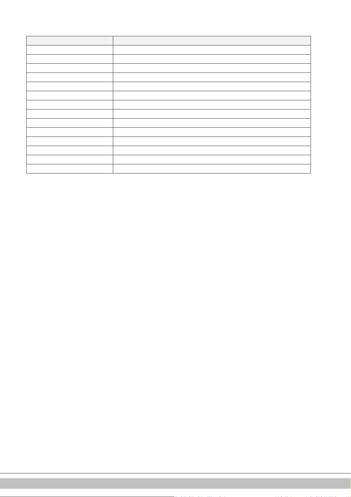
C93
Art.nr. Beschreibung
EKFGP4678 Kaminanschluss 60/100
EKFGP1856 Flex. Kit PP Ø60-80
EKFGP6340 Verlängerung flex. PP 80 L=10 m
EKFGP6344 Verlängerung flex. PP 80 L=15 m
EKFGP6341 Verlängerung flex. PP 80 L=25 m
EKFGP6342 Verlängerung flex. PP 80 L=50 m
EKFGP6324 Anschluss flex.-flex. PP 80
EKFGP4664 Bogen PP/GLV 60/100 30°
EKFGP4661 Bogen PP/GLV 60/100 45°
EKFGP4660 Bogen PP/GLV 60/100 90°
EKFGP6333 Distanzstück PP 80-100
EKFGP4667 Mess-T-Stück mit Inspektionsplatte PP/GLV 60/100
EKFGP4631 Wandhalterung Ø100
EKFGP4651 Erweiterung PP/GLV 60/100 x 500mm
Daikin Europe NV
24
Page 75

VORSICHT
5.8 Anschluss an eine Abgasanlage ohne Lufteinlass (B23, B33)
• Achten Sie darauf, dass der Kesselraum den
behördlichen Vorschriften zum Anschluss einer
Abgasanlage gemäß B23 oder B33 entspricht
• Beim Anschluss des Kessels an eine
Abgasanlage gemäß B23 oder B33 entspricht die
Schutzart IP20 und nicht IP44
Allgemeine Montage
1. Schieben Sie die Verbrennungsgas-Auslassrohre ineinander.
Vom Gerät aus muss jedes Rohr in das vorige Rohr geschoben werden.
Montieren Sie ein nicht vertikales Verbrennungsgas-Auslassrohr geneigt zum Gerät (min.
5 mm/m).
5.8.1 Zulässige Rohrlängen von parallelen Luftzufuhr- und Verbrennungsgas-
Rohrsystemen
Zulässige Rohrlängen für B23 und B33 bei Verwendung von Ø80mm
C13 C33 C43 C53 C83
EHOBG12 & 18 ABV1 100 m 100 m 100 m 100 m 100 m
Daikin Europe NV
25
Page 76

5.9 Anschluss an eine abgedichtete Abgasanlage.
5.9.1 Rohrlängen
Mit zunehmendem Widerstand des Verbrennungsgasrohrs und der Luftzufuhrrohre nimmt die
Leistung des Geräts ab. Die maximal zulässige Leistungsabnahme beträgt 5%.
Der Widerstand der Luftzufuhr und des Verbrennungsgasauslasses hängt von der Länge,
dem Durchmesser und allen Komponenten des Rohrsystems ab. Für jede Gerätekategorie
sind die zulässigen Rohrgesamtlängen der Luftzufuhr und des Verbrennungsgasauslasses
angegeben.
5.9.2 Zulässige Rohrlängen bei konzentrischen
Verbrennungsgasrohrsystemen
Zulässige Rohrlängen bei Verwendung des konzentrischen Anschlusses 60/100
C13 C33
EHOBG12 & 18ABV1 10 m 11 m
Zulässige Rohrlängen bei Verwendung des konzentrischen Anschlusses 80/125
C13 C33 C93
EHOBG12 & 18ABV1 29 m 29 m Siehe Abschnitt 5.9.8
Wenden Sie sich bezüglich Tests zur Berechnung des Widerstands des Luftzufuhrund Verbrennungsgasabzugsrohrs und der Wandtemperatur am Ende des
Verbrennungsgasabzugsrohrs an den Hersteller.
Ersatzlängen
Bogen 90° R/D=1 2 m
Bogen 45° R/D=1 1 m
Kniestück 90° R/D=0,5 4 m
Kniestück 45° R/D=0,5 2 m
Allgemeine Montage:
Für alle Auslässe gelten die folgenden Montagevorschriften:
1. Schieben Sie das konzentrische Verbrennungsgas-Auslassrohr und das
Luftzufuhrrohr auf.
2. Schieben Sie die konzentrischen Rohre ineinander.
Vom Gerät aus muss jedes Rohr in das vorige Rohr geschoben werden.
3. Montieren Sie ein nicht vertikales Verbrennungsgas-Auslassrohr geneigt zum Gerät
(min. 5 mm/m).
4. Bringen Sie die Montagehalter gemäß der Montageanleitung des Herstellers des
Luftzufuhr-/Verbrennungsgas-Rohrsystems an.
Daikin Europe NV
26
Page 77

5.9.3 Zulässige Rohrlängen von parallelen Luftzufuhr- und
Verbrennungsgas-Rohrsystemen
Zulässige Rohrlängen bei Ø80 mm (Verbrennungsgas- und Luftzufuhrrohr
zusammen).
C13 C33 C43 C53 C83
EHOBG12 & 18ABV1 100 m 100 m 100 m 100 m 100 m
Ersatzlängen
Bogen 90° R/D=1 2 m
Bogen 45° R/D=1 1 m
Kniestück 90° R/D=0,5 4 m
Kniestück 45° R/D=0,5 2 m
Berechnungsbeispiel
Rohr Rohrlängen Rohrgesamtlänge
Verbrennungsg
L1 + L2 + L3 + 2x2 m 13 m
asauslass
Luftzufuhr L4 + L5 + L6 + 2x2 m 12 m
Note:
Die Rohrgesamtlänge ist die Summe der geraden Rohrlängen + die Summe der
Ersatz-Rohrlängen von Biegungen/Kniestücken, also insgesamt 25 m. Wenn dieser
Wert geringer als die maximal zulässige Rohrlänge ist, entspricht der
Verbrennungsgasauslass den Anforderungen dieses Punkts.
Daikin Europe NV
27
Page 78

5.9.4 Frei auf dem Markt verfügbare Abzugs-Materialien (C63).
+0,3
-
0,7
+0,3
-
0,7
+2
-0
+0,3
-
0,7
+2
-0
Die Eigenschaften der Verbrennung bestimmen die Wahl des Abzugsmaterials.
Die Normen EN 1443 und EN 1856-1 bieten die erforderlichen Informationen zur Auswahl
des Abzugsmaterials mithilfe eines Aufklebers einschließlich Identifikations-Zeichenfolge.
Die Identifikations-Zeichenfolge enthält die folgenden Informationen:
A CE-Kennzeichnung
B Zu beachtende Norm: Metall, EN 1856-2
Kunststoff, EN 14471
Die Identifikations-Zeichenfolge muss die folgenden Informationen enthalten
C Temperaturklasse : T120
D Druckklasse : Druck (P) oder Hochdruck (Hi)
E Widerstandsklasse : W (Nass)
F Widerstandsklasse bei Bränden: : E
Maße C63 Abgasanlage (Außenmaße in mm)
Parallel Konzentrisch 80/125 Konzentrisch 60/100
Rauchabzugsrohr Lufteinlass Rauchabzugsrohr Lufteinlass
ø 80
ø 80
ø 125
ø 60
ø 100
Abzugsmaterialen verschiedener Hersteller dürfen nicht
kombiniert werden!
Daikin Europe NV
28
Page 79

5.9.5 Sicherung der Abgasanlage
WICHTIG
• Diese Bestimmungen sind für beide Typen von Abgasanlagen
(konzentrisch und parallel) typisch.
• Die Abgasanlage muss an einer festen Struktur befestigt werden.
• Die Abgasanlage sollte über einen kontinuierlichen Rückfall zum Kessel
verfügen (1,5° bis 3°). Hinweis: Wandanschlüsse müssen bündig
abschließend montiert werden.
• Verwenden Sie nur die mitgelieferten Halterungen.
• Jeder Bogen muss mit der Halterung befestigt werden.
Ausnahme beim Anschluss am Kessel: Wenn die Länge der Rohre vor
und nach dem ersten Bogen weniger als 250 mm beträgt, muss das
zweite nach dem ersten Bogen eine Halterung aufweisen.
Hinweis: Die Halterung muss am Bogen angebracht werden!
• Jede Verlängerung muss jeden Meter mit einer Halterung befestigt
werden.
Diese Halterung darf nicht um das Rohr geklemmt werden, damit sich das
Rohr frei bewegen kann.
• Achten Sie darauf, dass die Halterung, je nach Lage der Halterung am
Rohr oder Bogen, richtig fixiert ist:
• Die Abzugsmaterialien verschiedener Hersteller dürfen nicht vermischt
werden.
Max. Abstand zwischen Klemmen
Vertikal Sonstiges
2000 mm 1000 mm
• Teilen Sie die Abschnitte zwischen den Halterungen gleichmäßig auf.
• Jedes System muss mindestens 1 Halterung aufweisen.
• Bringen Sie die erste Klammer im Abstand von maximal 500 mm zum Kessel an.
Daikin Europe NV
29
Page 80

Daikin Europe NV
30
Page 81

5.9.6 Luftzufuhr von der Fassade aus und Dachabzug über
•
kommunales Abgassystem
Gerätekategorie: C83
Eine Luftzufuhr von der Fassade aus und ein Dachabzug über ein kommunales
Abgassystem ist zulässig.
WICHTIG
Die Luftzufuhr in der Fassade muss mit einem Einlassgitter
(A) ausgestattet werden.
• Das kommunale Abzugssystem muss mit einer Zug-
Abzugshaube (B) ausgestattet sein.
• Wenn sich das kommunale Abzugssystem im Freien
befindet, muss das Abzugsrohr doppelwandig oder isoliert
sein.
Zulässige Rohrlängen
Verbrennungsgas-Abzugsrohr zwischen dem Gerät und dem kommunalen
Abzugssystem und Luftzufuhrrohr zwischen dem Gerät und dem Einlassgitter
zusammen:
EHOBG12ABV1 100 m
EHOBG18ABV1 100 m
Mindestdurchmesser des kommunalen Abzugssystems basierend auf dem
Vakuum
Verbrennungsgasrohr –
Durchmesser (mm)
Anzahl der
Einheiten
2 130
3 150
4 180
5 200
6 220
7 230
8 250
9 270
10 280
11 290
12 300
Kommunaler Verbrennungsgasabzug
Der Auslass des Verbrennungsgas-Abzugsrohrs kann an jeder beliebigen Stelle der
Schrägdachfläche erfolgen, vorausgesetzt das der Auslass in der Dachfläche
dieselbe Ausrichtung wie der Lufteinlass in der Fassade hat. Auf einem Flachdach
muss der Auslass des Verbrennungsgas-Abzugsrohrs in einen "freien"
Auslassbereich erfolgen.
Bringen Sie einen Kondensatauslass an.
Hinweis
Der kommunale Abzug wird in Verbindung mit dem Gerät genehmigt.
EHOBG12ABV1 & EHOBG18ABV1
Daikin Europe NV
31
Page 82

5.9.7 Kombiniertes Verbrennungsgasabzugs-/Luftzufuhrsystem
Gerätekategorie: C43
WICHTIG
• Ein Dachabzug über ein kombiniertes
Luftzufuhr/Verbrennungsgas-Abzugssystems ist zulässig.
• Für die kommunale Verbrennungsgas-Abzugshaube und die
Luftzufuhrhaube muss eine Erklärung, dass keine Einwände
bestehen, oder ein Gaszertifikat vom Gastec Gas Institute
vorliegen.
• Die Durchführung der Druckausgleichsöffnung unten am
kommunalen Luftzufuhr/Verbrennungsgas-Abzugssystem
entspricht dem 0,44-fachen der VerbrennungsgasAbzugsoberfläche.
ie kommunale Luftzufuhr und der kommunale Verbrennungsgas-Abzug können
konzentrisch oder separat ausgeführt werden.
Zulässige Rohrlängen
Für parallelen Anschluss: Luftzufuhr- und Verbrennungsgas-Abzugsrohr zusammen
ohne die Länge der Kombi-Durchführung.
Für konzentrischen Anschluss: Rohrgesamtlänge ohne die Länge der KombiDurchführung.
EHOBG12ABV1 100 m 10 m 29 m
EHOBG18ABV1 100 m 10 m 29 m
Die minimalen Durchmesser des kommunalen
Luftzufuhr/Verbrennungsgassystems basieren auf dem Ergänzungsblatt 2001-02
Inspektionsanforderungen Nr. 138 von Gastec.
EHOBG12ABV1 & EHOBG18ABV1
Anzahl der
Einheiten Konzentrisch Parallel
Verbrennungsgas
(mm)
2 135 253 135 214
3 157 295 157 249
4 166 311 166 263
5 175 328 175 278
6 184 345 184 292
7 193 362 193 306
8 201 376 201 318
9 210 393 210 332
10 219 410 219 347
11 228 427 228 361
12 237 444 237 375
13 246 461 246 389
14 255 478 255 404
15 264 494 264 418
16 272 509 272 431
17 281 526 281 445
18 290 543 290 459
19 299 560 299 473
20 308 577 308 488
Parallel Konzentrisch
60/100
Luftzufuhr
(mm)
Verbrennungsgas
(mm)
Konzentrisch
er 80/125
Luftzufuhr
(mm)
D
Daikin Europe NV
32
Page 83

5.9.8 Konzentrischer horizontal Verbrennungsgasabzug, vertikaler, von
Luftschacht umgebener Teil
Gerätekategorie: C93
Ein Abgasssystem gemäss Kategorie C93 is gestattet wenn die Abgasteile eine CE
markierung haben oder von Daikin geliefert sind.
Unten stehende Punkten müssen unbedingt eingehalten werden
Allgemein
• Abgasleitung im Schaft in starr oder flexibel 60 oder 80 mm
• Bei Benutzung von einen Kunststoff Rohr soll die die Temperaturklasse
T 120 erfüllen.
• Das Verbindungsstück zwischen das Konzentrisches Rohr und das vertikale
Abgasleitung im Schaft soll gemäß Vorschrift der Lieferant montiert und
unterstutzt werden.
• Die Vorschriften der Lieferant des Abgassystem sollen richtig und Vollständig
befolgt werden.
• Wenn die Montage stattfinden muss in eine existierende Anlage soll der
Schaft vorher inspiziert und gereinigt werden
• Die Dichtheit der Schaft muss sichergestellt sein.
Zulässige Rohrlängen
Bei Benutzung einer Schacht (zB. ein gemauerten Schornstein) als Luftzuführkanal ist
folgendes Anwendbar
Abgasrohr
Diameter (mm)
(Starr oder flexibel)
DN 60 115 x 115 135 11
Abmessung schaft [mm] Max. länge [mtr]
Eckig Rund
DN 80 135 x 135 155 29
Daikin Europe NV
33
Page 84

6 INBETRIEBNAHME DES GERÄTS UND DER INSTALLATION
6.1 Befüllen und Entlüften des Geräts und der Installation
6.1.1 ZH-System
1. Stecken Sie den Netzstecker des Geräts in eine Steckdose ein.
Das Gerät führt einen Selbsttest durch:
Das Gerät geht anschließend in die Einstellung "Aus" über:
Wartungsanzeige) und der ZH-Druck wird an der Temperaturanzeige angezeigt.
2. Schließen Sie den Füllschlauch an den Füll-/Ablasshahn an und füllen Sie die
Installation mit reinem Trinkwasser bis zu einem Druck zwischen 1 und 2 Bar, wenn
die Installation kalt ist (abzulesen an der Temperaturanzeige ).
3. Entlüften Sie das System mit dem manuellen Entlüfter (A).
Auf Wunsch kann die Installation mit einem automatischen Entlüfter anstelle des
manuellen Entlüfters ausgestattet werden.
4. Entlüften Sie die Installation mit den manuellen Entlüftern an den Radiatoren.
5. Füllen Sie die ZH-Installation auf, wenn der Druck aufgrund der Entlüftung zu tief
gesunken ist.
6. Überprüfen Sie alle Verbindungen auf Undichtigkeiten.
7. Stellen Sie sicher, dass der Siphon mit Wasser gefüllt ist.
Bei einem ZH-Druck unter 0,5 Bar wird der ZH-Druck
blinkend an der Anzeige angezeigt.
In der Einstellung "Aus" wird der ZH-Druck angezeigt.
WARNUNG
Wenn der Siphon nicht mit Wasser gefüllt ist, können
Verbrennungsgase in den Raum freigesetzt werden.
WARNUNG
Wenn ein Additiv zum ZH-Wasser hinzugegeben wird,
muss es für die im Gerät verwendeten Materialien wie
beispielsweise Kupfer, Messing, Edelstahl, Kunststoff
und Gummi geeignet sein. Das Additiv sollte
vorzugsweise über eine KIWA/ATA/A-Testbescheinigung
verfügen.
2
(an der Wartungsanzeige).
-
(an der
6.1.2 Warmwasserbereitstellung (nur gültig bei einem indirekt
befeuerten Speicher)
1. Öffnen Sie den Hauptwasserhahn, um den Druck im Warmwasserabschnitt zu
erhöhen.
2. Entlüften Sie den Speicher und das Leitungssystem, indem Sie einen
Warmwasserhahn öffnen. Lassen Sie den Wasserhahn geöffnet, bis alle Luft aus
dem System entwichen ist.
3. Überprüfen Sie alle Verbindungen auf Undichtigkeiten.
6.1.3 Gasversorgung
1. Entlüften Sie die Gasleitung mit dem Ausgangsdruck-Messnippel (D) am Gasblock.
2. Überprüfen Sie alle Verbindungen auf Undichtigkeiten.
3. Überprüfen Sie den Ausgangsdruck und den Offset-Druck (siehe Abschnitt 7.7).
Daikin Europe NV
34
Page 85

6.2 Inbetriebnahme der Einheit
Anzeige
Bedienung
1
EIN/AUS
A Ein/Aus
-
Taste
2
ZH-Betrieb oder Einstellen der maximalen ZH
-
Temperatur
B Hahn/ZH
-
Taste, zur Einstellung der Soll
-
Temperatur
3
Hahnbetrieb oder Einstellung der Hahntemperatur
C - Taste
4
Solltemperatur ZH oder
Warmwasser
in °C / Druck ZH
-
Warmwasser
in Bar / Störungscode
D + Taste
E
Hahn-Komfortfunktion Aus/Eco/Ein (nicht gültig für Geräte
5
Hahn-Komfortfunktion Eco (nicht gültig für Geräte des Typs
EHOBG
*
ABV1)
des Typs
EHOBG
*
ABV1)
6
Hahn-Komfortfunktion Ein (nicht gültig für Geräte des Typs
EHOBG
*
ABV1) F Wartungstaste / Tatsächliche Temperatur während
7
Betriebscode
Heizanforderung
8
Blinkend bei einer Störung
G Reset-Taste
Nach Abschluss der folgenden Vorgänge kann das Gerät in Betrieb genommen werden.
1. Drücken Sie die Taste , um das Gerät in Betrieb zu nehmen.
Der Wärmetauscher wird aufgeheizt, und an der Wartungsanzeige wird
Eco-Schalters und/oder der OpenTherm-Regelung).
2. Stellen Sie die Pumpeneinstellung abhängig von der eingestellten maximalen Leistung und dem wasserseitigen Widerstand der Installation
ein. Informationen zur Wassersäule der Pumpe und dem Druckverlust des Geräts finden Sie in Abschnitt 7.4.
3. Stellen Sie das Raumthermostat höher als die Raumtemperatur ein. Das Gerät geht in den ZH-Betrieb über:
Wartungsanzeige angezeigt.
4. Heizen Sie die Installation auf.
5. Überprüfen Sie den Temperaturunterschied zwischen dem Zulauf und dem Rücklauf des Geräts und der Radiatoren.
Dieser sollte etwa 20°C betragen. Stellen Sie zu diesem Zweck die maximale Leistung an der Wartungsanzeige ein (siehe Abschnitt 7.3).
Passen Sie ggf. die Pumpeneinstellung und/oder die Absperrventile der Radiatoren an. Die Standardeinstellung der Pumpe ist die
Einstellung 3. Der minimale Durchfluss beträgt:
155 l/Std. bei einer eingestellten Leistung von 5,4 kW
510 l/Std. bei einer eingestellten Leistung von 17,8 kW
6. Schalten Sie das Gerät aus.
7. Entlüften Sie das Gerät und die Installation, nachdem sich diese abgekühlt haben (füllen Sie bei Bedarf Wasser nach).
8. Überprüfen Sie die Heizfunktion und die Warmwasserbereitstellung auf ordnungsgemäße Funktionsweise.
9. Weisen Sie den Benutzer in die Befüllung, Entlüftung und Funktionsweise des Heizbetriebs und der Warmwasseraufbereitung ein.
Kommentare
• Das Gerät ist mit einer elektronischen Speichersteuerung ausgestattet, die den
Brennerautomaten zündet und die Flamme bei jeder Heizanforderung von der
Heizung oder von der Warmwasserbereitstellung kontinuierlich überwacht und regelt.
• Die Umlaufpumpe läuft bei jeder Heizanforderung durch die Heizung. Die Pumpe hat
eine Nachlaufzeit von 1 Minute. Die Nachlaufzeit kann auf Wunsch geändert werden
(siehe Abschnitt 7.3).
• Die Pumpe wird automatisch 1 Mal alle 24 Stunden für 10 Sekunden betrieben, um
Verstopfungen zu vermeiden. Diese automatische Einschaltung der Pumpe erfolgt
24 Stunden nach der letzten Heizanforderung. Um den Zeitpunkt zu ändern, muss
das Raumthermostat zum gewünschten Zeitpunkt für einen moment hochgedreht
werden.
• Für die Warmwasserbereitstellung wird die Pumpe nicht in Betrieb genommen.
3., 4
und 7 angezeigt (abhängig vom Status des externen
5
wird an der
Daikin Europe NV
35
Page 86
6.3 Ausschalten des Geräts
VORSICHT
Lassen Sie das Wasser aus dem Gerät und der
Installation ab, wenn die Stromversorgung
unterbrochen ist und die Gefahr des Einfrierens
besteht.
1. Entfernen Sie den Netzstecker aus der Steckdose.
2. Lassen Sie das Wasser mit Hilfe des Füll-/Ablasshahns ab.
3. Lassen Sie das Wasser aus der Installation am tiefsten Punkt ab.
4. Schließen Sie den Haupthahn für die Wasserversorgung des
Warmwasserabschnitts.
5. Lassen Sie das Wasser aus dem Gerät ab, indem Sie die
Warmwasseranschlüsse unter dem Gerät lösen.
6. Leeren Sie den Siphon.
6.3.1 Frostschutz
• Um das Einfrieren des Kondensatauslasses zu verhindern, muss das Gerät in
einem frostfreien Raum installiert werden.
• Das Gerät mit einer Frostschutzfunktion ausgestattet, um ein Einfrieren des Geräts
zu verhindern. Wenn die Temperatur des Wärmetauschers zu tief sinkt, wird der
Pumpenbetrieb gestartet, bis der Wärmetauscher ausreichend aufgeheizt ist.
Wenn die Gefahr besteht, dass die Installation (oder ein Teil hiervon) einfrieren
kann, sollte die kälteste Stelle mit einem (externen) Frostschutzthermostat an der
Rückleitung ausgestattet werden. Dieses muss gemäß dem Schaltplan
angeschlossen werden (siehe Abschnitt 10.3).
Hinweis
Wenn ein (externes) Frostschutzthermostat an der Installation montiert und an das
Gerät angeschlossen wurde, ist dieses nicht aktiv, wenn das Gerät am Bedienteil
ausgeschaltet wurde (
-
an der Wartungsanzeige ).
Daikin Europe NV
36
Page 87

7 EINSTELLUNGEN UND ANPASSUNGEN
Die Funktionsweise des Geräts kann mittels der (Parameter-) Einstellungen in der
Kesselsteuerung beeinflusst werden. Einige dieser Einstellungen können direkt über die
Bedientafel konfiguriert werden, andere wiederum können nur nach Eingabe des Monteurcodes
angepasst werden.
7.1 Direkt über das Bedienteil
Die folgenden Funktionen können direkt bedient werden.
Gerät Ein/Aus
Die Taste aktiviert das Gerät.
Wenn das Gerät aktiv ist, leuchtet die grüne LED über der Taste . Wenn das Gerät
ausgeschaltet ist, leuchtet ein Balken an der Wartungsanzeige (
dass das Gerät an die Stromversorgung angeschlossen ist. In dieser
Betriebseinstellung zeigt die Temperaturanzeige auch den Druck in der ZH-Installation
an (in Bar).
Sommerbetrieb .
Wenn Parameter q auf einen Wert anders als 0 Sommerbetrieb eingestellt ist können Sie die
Taste Taste aktiviert werden .
Im Sommerbetrieb die Heizung wurde abgeschaltet , während Warmwasser bleibt aktiv.
Sommerbetrieb kann durch Drücken der Taste aktiviert werden . wieder nach Aktivierung
des Kessels.
Auf dem Display [ So ], [ Su ] oder [ Et ] erscheint (der Code auf dem Display hängt von der
Einstellung des Parameters q) .
Sommerbetrieb kann durch zweimaliges Drücken der Taste deaktiviert werden. Der Kessel
wird dann im normalen Funktionsmoduswieder .
Ändern der Einstellungen der verschiedenen Funktionen:
Durch Drücken der Taste für 2 Sekunden wird das Menü "Benutzereinstellungen" aufgerufen
(LED bei und die Nummernanzeige blinkt). Mit jeder Betätigung der Taste blinkt eine
andere Funktions-LED. Wenn die LED blinkt, kann die entsprechende Funktion mit den Tasten
bzw. eingestellt werden. Der eingestellte Wert wird an der -Anzeige angezeigt.
Durch Drücken der Ein/Aus-Taste wird das Menü "Benutzereinstellungen" geschlossen und
die Änderungen werden nicht gespeichert.
Durch Drücken der Reset-Taste wird das Menü "Benutzereinstellungen" geschlossen und
die Änderungen werden gespeichert.
Wenn innerhalb von 30 Sekunden keine Taste gedrückt wird, wird das Einstellungsmenü
automatisch geschlossen und die Änderungen werden gespeichert.
• Maximale ZH-Solltemperatur
Drücken Sie die Taste , bis die LED bei blinkt.
Verwenden Sie die Tasten bzw. , um die Temperatur zwischen 30°C und 90°C
einzustellen (Standardwert: 80°C).
• Speichertemperatur
Drücken Sie die Taste , bis die LED bei blinkt.
Verwenden Sie die Tasten bzw. , um die Temperatur zwischen 40°C und 65°C
einzustellen (Standardwert: 60°C).
Steuerung der externen Warmwasserspeicher
• Ein: ( LED an) , die externe Warmwasserspeicher wird kontinuierlich erwärmt.
• Eco : ( LED leuchtet). Der Kessel wird erhitzt werden / nicht beheizt , je nach den
Informationen von der Open Therm Thermostat senden ( sofern der Thermostat diese
Funktion unterstützt ) . Bei Verwendung eines Ein- / Aus- Raumthermostat oder eine
Open Therm Thermostat , die diese Funktion der Warmwasserspeicher nicht
unterstützt wird der Speicher kontinuierlich erwärmt.
• Aus : (Beide LEDs aus. ) Die Kessel wil nicht beheizt werden.
-
), um anzugeben,
Daikin Europe NV
37
Page 88

Legionellenschütz
Bei Anschluss eines externen Speichers mit Speicherfühler kann der Speicher einmal am Tag
oder einmal in der Woche durch Einstellen des Parameters L auf eine Temperatur > 65°C
erwärmt werden. Siehe auch § 0 .
Zurücksetzen des Geräts (Reset)
Ermitteln Sie die Art der Störung anhand der Störungscodes in Abschnitt 8.1 und beheben Sie,
falls möglich, die Ursache der Störung, bevor Sie das Gerät zurücksetzen.
Wenn eine das Gerät blockierende Störung durch eine blinkende LED über der Taste und
eine Zahl an der Anzeige angezeigt wird, kann das Gerät durch Drücken der Reset-Taste
zurückgesetzt werden.
7.2 Parametereinstellungen über den Wartungscode
Die Parameter des Brennerautomaten wurden werkseitig gemäß der folgenden Tabelle
konfiguriert.
Diese Parameter können nur nach Eingabe des Wartungscodes geändert werden. Gehen Sie
wie folgt vor, um den Programmspeicher zu aktivieren:
1. Drücken Sie gleichzeitig die Tasten und , bis eine
werden.
2. Verwenden Sie die Taste , um
3. Verwenden Sie die Taste , um den zu konfigurierenden Parameter an der Wartungsanzeige einzustellen.
4. Verwenden Sie die Tasten und , um den Parameter auf den gewünschten Wert (sichtbar) an der Temperaturanzeige einzustellen.
5. Nachdem Sie alle erforderlichen Änderungen vorgenommen haben, drücken Sie die Taste , bis P an der Wartungsanzeige angezeigt
wird.
Der Brennerautomat wurde jetzt neu programmiert.
Hinweis
Durch Drücken der Taste wird das Menü ohne Speicherung der Parameteränderungen geschlossen.
Beispiel: Ändern der maximalen Heizungsleistung
1. Drücken Sie die Tasten und gleichzeitig.
2. Verwenden Sie die Taste , um zu
3. Drücken Sie die Taste 3 x. 85 und 3 werden an der Anzeige angezeigt.
4. Verwenden Sie die Taste , um die 85 in 70 zu ändern.
5. Drücken Sie die Taste , bis P angezeigt wird.
6. Die Änderung wurde übernommen. Die maximale ZH-Leistung wurde von 85 auf 70% geändert.
Para- EHOBG*ABV1
meter Einstellung 12 18 Beschreibung
0 Wartungscode [15] - - Zugriff auf Monteureinstellungen, Eingabe des Wartungscodes
1 Installationstyp 1 1 0= Kombi
2 Einstellungen Heizkreispumpe 0 0 0= Nur Pumpennachlauf
3 Max. Brennerleistung im Heizungsbetrieb
3. Maximale Pumpenleistung
4 Einstellung der maximalen
Warmwasserleistung
5 Sollvorlauftemperatur bei höchster
Außentemperatur der Heizkurve
(Parameter 7)
5. Max. Vorlauftemperatur einstellbar über das
Bedienfeld
6 Niedrigste Außentemperatur der Heizkurve -7 -7 Einstellungsbereich -30 bis 10°C
7 Höchste Außentemperatur der Heizkurve 25 25 Einstellungsbereich 15°C bis 30°C
15
(Wartungscode) an der Temperaturanzeige einzugeben.
15
zu gelangen.
0
an der Wartungsanzeige und eine
erforderlich (=15)
1= Heizen und Warmwasser über externen Speicher
2= Nur Warmwasser
3= Nur Heizen
1= Pumpe kontinuierlich aktiv
2 – 5 = nicht aktiv
99 85 Einstellungsbereich: Wert des Sollwertparameters c bis 100%
(100 % = 99 + 1x Taste drücken).
80 80 Einstellungsbereich: Wert des Sollwertparameters c. bis
100%. (100 % = 99 + 1x Taste drücken ).
80 80 Einstellungsbereich: Wert des Sollwertparameters d bis
100%. (100 % = 99 + 1x Taste drücken ).
25 25 Einstellungsbereich: 10°C bis Einstellwert von Parameter 5.
90 90 Einstellungsbereich 30°C bis 90°C
0
an der Temperaturanzeige angezeigt
Daikin Europe NV
38
Page 89
8 Pumpennachlaufzeit im Heizbetrieb 1 1 Einstellungsbereich 0 bis 15 Minuten
9 Pumpennachlaufzeit im Speicherlade-betrieb 0 0 Einstellungsbereich 0 bis 15 Minuten
(nicht zutreffend für Kombi-Gerät)
A Einstellung 3-Wege-Ventil oder Absperrventil 0 0 0= eingeschaltet während ZH-Betrieb
1= eingeschaltet während Warmwasserbetrieb und
Ruhephase
2= 3-Wege-Ventil in ZH-Einstellung, wenn Gerät nicht in
Standby
3= Zonenregelung
4 und höher= Nicht anwendbar
b Zusatzheizung 0 0 Nicht anwendbar
C Schrittweise Modulation 1 1 0= Schrittweise Modulation aus während ZH-Betrieb
1= Schrittweise Modulation ein während ZH-Betrieb
2= Leistungssteuerung durch Open Therm-Raumthermostat
aktiviert
c Minimale Brennerleistung im Heizungsbetrieb 30 30 Einstellungsbereich: 20 bis 50% der mit Parameter h
eingestellten maximalen Drehzahl
c. Minimale Pumpenleistung 40 40 Einstellungsbereich: 15 bis zum Einstellwert von Parameter 3.
d Minimale Brennerleistung im
Warmwasserbetrieb
E Min. Vorlauftemperatur bei OT (OpenTherm)
oder RF-Thermostat
E. Reaktion OT und RF-Raumthermostat 1 1 0= nicht auf Heizungsanforderung reagieren, wenn die
F
Mindest Drehzahl für Zündung bei Heizungsbetrieb.
F. Mindest Drehzahl für Zündung bei
Warmwasser-betrieb
h
Max. Drehzahl Lüfter 45 46 Einstellungsbereich 40 – 50. (EHOB12ABV1H und
L Legionellenschutz 0 = Legionellenschutz nicht aktiv
n Sollwert Vorlauftemperatur bei
Warmwasserbetrieb.
n. Warmwassertemperatur bei Komfort/Eco 0 0 Nicht anwendbar
O. Wartezeit bei Heizungsanforderung.
(eine Heizungs-Anforderung wird erst nach
Ablauf der mit diesem Parameter eingestellten
Wartezeit bedient).
o Wartezeit ZH-Betrieb nach
Warmwasserbetrieb
o. Anzahl der Eco-Tage 3 3 Nicht anwendbar
P Anti-Anlaufzeit während ZH-Betrieb 5 5 Minimale Ausschaltzeit bei ZH-Betrieb
P. Referenzwert Warmwasser 0 0 Nicht anwendbar
q Sommerbetrieb 0 0 0 = Sommerbetrieb deaktiviert
r Parallel-Verschiebungs-Konstante 0 0 Nicht anwendbar
30 30 Einstellungsbereich: 20 bis 50% der mit Parameter h
eingestellten maximalen Drehzahl
40 40 Einstellungsbereich 10 – 60°C
angeforderte Temperatur niedriger ist als der mit Parameter
E eingestellte Wert.
1= auf Heizungsanforderung reagieren mit minimaler
Vorlauftemperatur, begrenzt auf den mit Parameter E
festgelegten Wert.
2= auf Heizungsanforderung mit maximaler Vorlauftemperatur
reagieren (Ein/Aus-Funktion)
Keine Modulation der Vorlauftemperatur.
70 70 Einstellungsbereich 40 – 99% der der mit Parameter h
eingestellten maximalen Drehzahl
70 70 Einstellungsbereich 40 – 99% der der mit Parameter h
eingestellten maximalen Drehzahl
EHOB18ABV1H) oder 60-70 (EHOB42ABV1H)
Hinweis: Werkseitige Einstellung kann abweichen.
1 = Legionellenschutz 1 mal pro Woche
2 = Legionellenschutz 1 mal pro Tag
80 80 Einstellungsbereich 60°C - 90°C
0 0 Einstellungsbereich 0 – 15 Minuten
0 0 Nicht anwendbar
Einstellbereich: 0 - 15 Minuten
1 = Sommerbetrieb durch Taste aktiviert werden
( Anzeige im Display : Su )
2 = Sommerbetrieb durch Taste aktiviert werden
( Anziege im Display : So)
3 = Sommerbetrieb durch Taste aktiviert werden
( Anzeige im Display : Et)
Daikin Europe NV
39
Page 90
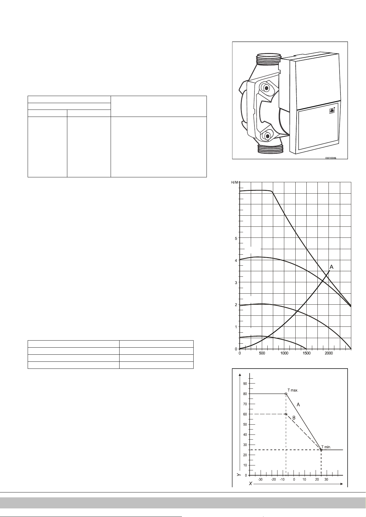
7.3 Einstellung der maximalen ZH-Leistung
6
7
100 %
75 %
50 %
25 %
Die maximale ZH-Leistung ist werkseitig auf 70% eingestellt. Wenn mehr Leistung für
die ZH-Installation erforderlich ist, kann die maximale ZH-Leistung durch Anpassung
der Drehzahl (U/min) des Lüfters geändert werden. Siehe Tabelle: Einstellen der ZHLeistung.
Diese Tabelle zeigt die Beziehung zwischen der Drehzahl des Lüfters und der Leistung
des Geräts.
ZH-Sollleistung in kW (ca.) Einstellungen an der Wartungsanzeige
EHOBG*ABV1
(in % der maximalen Drehzahl)
12 18
12,5 - 100
10,4 18,7 85
9,2 16,8 80
8,1 14,8 70
6,9 12,7 60
5,8 10,6 50
4,6 8,3 40
3,4 6,4 30
- 5,4 25
Vorsicht:
Die Leistung wird langsam gesteigert, wenn die Flamme brennt, und gesenkt, wenn die
Soll-Vorlauftemperatur erreicht ist (Modulation bei Ta).
7.4 Festlegung der Pumpeneinstellungen
Die Heizungskessel des Typs EHOBG**ABV1 sind mit einer modulierenden Pumpe der AKlasse ausgestattet, die die Leistung auf der Basis der gelieferten ZH-Leistung moduliert. Die
minimale und maximale Kapazität der Pumpe kann mit den Parametern 3 und c angepasst
werden. Siehe auch Abschnitt 7.2.
Der Sollwert von Parameter 3. (max. Pumpeneinstellung) ist der Prozentsatz der maximalen
Pumpenkapazität und ist mit der eingestellten maximalen ZH-Leistung wie in Parameter 3
festgelegt verknüpft.
Der Sollwert von Parameter c. (min. Pumpeneinstellung) ist mit der minimalen ZH-Leistung
wie in Parameter c festgelegt verknüpft.
Wenn die ZH-Last zwischen dem minimalen und maximalen Wert moduliert, wird die
Pumpenkapazität entsprechend proportional moduliert.
Druckverlustgraphik ZH-seitig
A EHOBG12ABV1 & EHOBG18ABV1
X Überlauf ZH-Kreislauf in l/Std.
Y Druckverlust / Wasserdruckhöhe in mH2O
Minimale Durchflussmenge Eingestellte Leistung
155 l/Std. 5,4 kW
240 l/Std. 8,5 kW
510 l/Std. 17,8 kW
7.5 Witterungsgeführte Regelung
Bei Anschluss eines Außentemperaturfühlers wird die Vorlauftemperatur automatisch
abhängig von der Außentemperatur in Übereinstimmung mit der eingestellten Heizkurve
reguliert.
Die maximale Vorlauftemperatur (T max) wird über die Anzeige eingestellt. Falls gewünscht
kann die Heizkurve mittels des Wartungscodes geändert werden (siehe Abschnitt 7.3).
Heizkurve
X. T außen in °C
Y. T Vorlauftemperatur in °C
A. Werkseitige Einstellung
B. Beispiel
Daikin Europe NV
(Tmax ZH = 80°C, Tmin ZH = 25°C, Tmin außen = -7°C, Tmax außen = 25°C)
(Tmax ZH = 60°C, Tmin ZH = 25°C, Tmin außen = -7°C, Tmax außen = 25°C)
40
Page 91
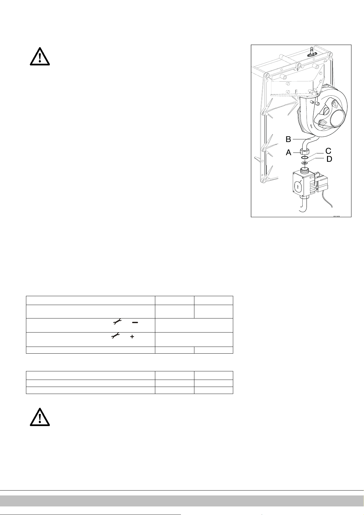
7.6 Wechsel zu einem anderen Gastyp
VORSICHT
Arbeiten an gasführenden Teilen dürfen nur von einem
qualifizierten Monteur durchgeführt werden.
Wenn ein Gerät an einen anderen als den vom Hersteller eingestellten Gastyp angeschlossen
wird, muss der Gasdosierring ersetzt werden. Konvertierungssätze für andere Gastypen können
bestellt werden.
Wechseln des Dosierrings
1. Schalten Sie den Kessel ab und ziehen Sie den Netzstecker von der Steckdose.
2. Schließen Sie das Gasventil.
3. Entfernen Sie die Frontabdeckung vom Gerät.
4. Lösen Sie die Verbindungsmuffe (A) über dem Gasblock und drehen Sie den Gasmischrohr (B)
nach hinten.
5. Ersetzen Sie den O-Ring (C) und den Gasdosierring (D) durch die Ringe des
Konvertierungssatzes.
6. Bauen Sie das Gerät in umgekehrter Reihenfolge wieder zusammen.
7. Öffnen Sie das Gasventil.
8. Überprüfen Sie, dass die Gasanschlüsse vor dem Gasblock dicht sind.
9. Stecken Sie den Netzstecker in die Steckdose und schalten Sie den Kessel ein.
10. Überprüfen Sie, dass die Gasanschlüsse nach dem Gasblock dicht sind (im Betrieb).
11. Überprüfen Sie jetzt die Einstellung des Gas/Luft-Verhältnisses (siehe Abschnitt 0).
12. Bringen Sie einen Aufkleber des konfigurierten Gastyps auf dem vorhandenen Aufkleber auf dem
Gasblock an.
13. Bringen Sie einen Aufkleber des konfigurierten Gastyps auf dem Typschild an.
14. Bringen Sie die Frontabdeckung wieder am Gerät an.
7.7 Gas/Luft-Regelung
Die Gas/Luft-Regelung wurde werkseitig eingestellt und erfordert im Allgemeinen keine
Anpassung.
Die Einstellung kann geprüft werden, indem Sie den CO2-Prozentwert in den
Verbrennungsgasen oder den Druckunterschied messen.
Bei einer Änderung an der Installation wie etwa dem Austausch des Gasblocks oder dem
Wechsel zu einem anderen Gastyp muss die Regelung überprüft und gemäß der folgenden
Tabelle eingestellt werden.
Gastyp Erdgas H Propangas P
Gaskategorie
CO2% in der Einstellung "Kleinlast" (L) ( und )
Mit offener Abdeckung
CO2% in der Einstellung "Volllast" (H) ( und 2x)
Mit offener Abdeckung
Anfangsgasdruck (mbar) 20 50
Gasdosierring Erdgas H Propangas P
EHOBG12ABV1 460 315
EHOBG18ABV1 505 410
VORSICHT
Die CO2-Prüfung muss mit offener Abdeckung durchgeführt
werden. Wenn die Abdeckung geschlossen ist, kann der CO2Prozentsatz höher als die in der Tabelle angegebenen Werte
liegen.
2E/H G20
Siehe Abschnitt 7.8
Siehe Abschnitt 7.8
3P / G31
30 / 37 / 50
Daikin Europe NV
41
Page 92
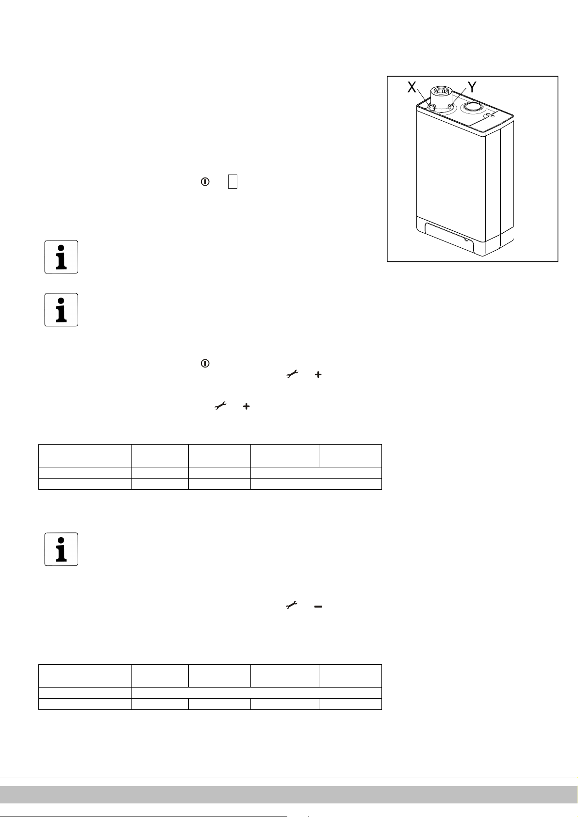
7.8 Einstellen der Gas/Luft-Regelung
Die CO2-Einstellung wurde werkseitig vorgenommen und erfordert im Allgemeinen keine
Anpassung. Die Einstellung kann geprüft werden, indem Sie den CO2-Prozentwert in den
Verbrennungsgasen messen. Bei einer Änderung an der Installation wie etwa dem Austausch des
Gasventils oder einem Wechsel zu einem anderen Gastyp muss die Einstellung geprüft und
erforderlichenfalls entsprechend den folgenden Anweisungen angepasst werden. Prüfen Sie den
CO2-Prozentwert immer, wenn die Abdeckung entfernt ist.
Überprüfen der Kohlendioxideinstellung
1 Schalten Sie den Kessel über die Bedieneinheit aus.
2 Schalten Sie den Gaskessel mit der Taste aus.
3 Entfernen Sie die Frontabdeckung vom Gaskessel.
4 Entfernen Sie die Abdeckung vom Messpunkt (X) und führen Sie eine geeignete
Kaminmesssonde ein.
WICHTIG
Stellen Sie sicher, dass das Anlaufverfahren des Messgeräts abgeschlossen
wurde, bevor Sie die Sonde am Messpunkt einführen.
WICHTIG
Warten Sie, bis der Gaskessel stabil läuft. Wird die Messsonde eingeführt,
bevor der Kessel stabil läuft, kann es zu fehlerhaften Messwerten kommen. Es
wird empfohlen, mindestens 30 Minuten zu warten.
-
wird an der Wartungsanzeige angezeigt.
5 Schalten Sie den Gaskessel mit der Taste ein und fordern Sie die Raumheizung an.
6 Wählen Sie die Einstellung "Volllast", indem Sie zweimal die Tasten und gleichzeitig
drücken. Der Großbuchstabe "H" wird an der Wartungsanzeige angezeigt. An der Bedieneinheit
wird das "Belegt"-Symbol angezeigt. Führen Sie KEINEN Test durch, wenn der Kleinbuchstabe
"h" angezeigt wird. Drücken Sie in diesem Fall und noch einmal.
7 Warten Sie, bis sich die angezeigten Werte stabilisiert haben. Warten Sie mindestens 3 Minuten
und vergleichen Sie den CO2-Prozentwert mit den Werten in der folgenden Tabelle.
CO2-Wert bei
maximaler Leistung
Höchstwert 9,6 8,3 10,8
Mindestwert 8,4 7,3 9,8
8 Schreiben Sie den CO2-Prozentwert bei maximaler Leistung auf. Dies ist für die nächsten
Schritte wichtig.
9 Wählen Sie die Einstellung "Kleinlast", indem Sie einmal die Tasten und gleichzeitig
drücken. "L" wird auf der Wartungsanzeige eingeblendet. An der Bedieneinheit wird das
"Belegt"-Symbol angezeigt.
10 Warten Sie, bis sich die angezeigten Werte stabilisiert haben. Warten Sie mindestens 3 Minuten
und vergleichen Sie den CO2-Prozentwert mit den Werten in der folgenden Tabelle.
CO2-Wert bei
minimaler Leistung
Höchstwert (a)
Mindestwert 8,4 7,4 9,4 9,4
11 Wenn der CO
Tabellen oben angegebenen Bereichs liegt, ist die CO2-Einstellung des Kessels korrekt.
Falls NICHT, passen Sie die CO2-Einstellung gemäß den im folgenden Kapitel
aufgeführten Anweisungen an.
WICHTIG
Es ist NICHT möglich, den CO2-Prozentwert anzupassen, während das
Testprogramm ausgeführt wird. Wenn der CO2-Prozentwert von den Werten in
der Tabelle oben abweicht, wenden Sie sich an die zuständige
Kundendienstabteilung.
(a) CO2-Wert bei maximaler Leistung, erfasst in der Einstellung "Volllast".
-Prozentwert bei maximaler und minimaler Leistung innerhalb des in den
2
Erdgas G20 Erdgas G25 Propangas G31
(30/50 mbar)
Erdgas G20 Erdgas G25 Propangas G31
(30/50 mbar)
Propangas
G31 (37 mbar)
Propangas
G31 (37 mbar)
Daikin Europe NV
42
Page 93

12 Schalten Sie das Gerät durch Drücken der Taste aus und bringen Sie die
erändert und/oder
03010102
A
B
Messpunktabdeckung wieder am ursprünglichen Ort an. Stellen Sie sicher, dass dort
kein Gas austreten kann.
13 Bringen Sie die Frontabdeckung wieder an.
VORSICHT
Arbeiten an gasführenden Teilen dürfen NUR von
qualifizierten Personen durchgeführt werden.
Anpassen der Kohlendioxideinstellung
WICHTIG
Ändern Sie die CO2-Einstellung nur, wenn Sie sie zuvor überprüft haben und
sicher sind, dass eine Änderung notwendig ist. Ohne vorherige Genehmigung
Ihres lokalen Daikin-Händlers dürfen keine Anpassungen am Gasventil
vorgenommen werden. In Belgien darf das Gasventil NICHT v
das Siegel NICHT entfernt oder beschädigt werden. Wenden Sie sich an Ihren
Händler.
1 Entfernen Sie die Abdeckung (A) der Stellschraube.
2 Drehen Sie die Schraube (B) nach rechts, um den CO2-Prozentsatz zu erhöhen,
oder nach links, um ihn zu verringern. In der folgenden Tabelle finden Sie die
entsprechenden Werte.
Gemessener Wert
bei maximaler
Leistung
10,8 - 10,5±0,1
10,6 10,3±0,1
10,4 10,1±0,1
10,2 9,9±0,1
10 9,8±0,1
9,8 9,6±0,1
9,6 9,0±0,1 9,4 8,9±0,1
9,2 8,8±0,1
9,0 8,7±0,1
8,8 8,6±0,1
8,6 8,5±0,1
3 Nach dem Messen des CO2-Prozentwerts und Ändern der Einstellung bringen Sie
die Abdeckkappe und die Kappe der Probenahmestelle wieder an Ort und Stelle
an. Stellen Sie sicher, dass diese gasdicht sind.
4 Wählen Sie die Einstellung "Volllast", indem Sie zweimal die Tasten und
gleichzeitig drücken. Der Großbuchstabe wird an der Wartungsanzeige
angezeigt.
5 Messen Sie den CO2-Prozentwert. Wenn der CO2-Prozentwert weiterhin von den
Werten in der Tabelle mit den CO2-Prozentwerten bei maximaler Leistung
abweicht, wenden Sie sich an Ihren Händler vor Ort.
6 Drücken Sie gleichzeitig die Tasten + und -, um das Testprogramm zu beenden.
7 Bringen Sie die Frontabdeckung wieder an.
Eingestellte Werte CO2 (%) bei minimaler Leistung
(Frontabdeckung offen)
Erdgas 2H
(G20, 20 mbar)
Propangas 3P
(G31, 30/50/37 mbar)
Daikin Europe NV
43
Page 94

8 STÖRUNGEN
•
•
•
•
•
•
•
•
•
•
•
•
8.1 Anzeigen der letzten Störung
Verwenden Sie die Taste , um das Gerät auszuschalten, und drücken Sie dann die Taste .
Die rote Störungs-LED leuchtet kontinuierlich, und der letzte Störungscode wird blinkend an der Temperaturanzeige angezeigt.
Wenn das Gerät noch nie eine zur Unterbrechung des Betriebs führende Störung erkannt hat, wird kein Code angezeigt.
Die letzte zu einer Unterbrechung des Betriebs führende Störung kann durch kurzes Drücken der Taste bei gedrückt gehaltener
Taste gelöscht werden.
8.2 Störungscodes
Wenn die Störungs-LED blinkt, hat die Kesselsteuerung eine Störung erkannt. Ein Störungscode wird an der Temperaturanzeige
angezeigt.
Wenn die Störung behoben ist, kann die Kesselsteuerung durch Drücken der Reset-Taste neu gestartet werden.
Nachfolgend sind die Störungscodes und deren Bedeutungen sowie mögliche Maßnahmen zur Behebung aufgeführt:
Temperaturanzeige Beschreibung Mögliche Ursache/Lösung
10, 11, 12, 13, 14 Fühlerfehler S1
20, 21, 22, 23, 24 Fühlerfehler S2
0 Fühlerfehler nach
Selbstprüfung
1 Temperatur zu hoch
2 Schalter S1 und S2
4 Kein Flammensignal
5 Schlechtes Flammensignal
6 Flammenerkennungsfehler
8 Lüfterdrehzahl ist falsch.
27 Kurzschluss
Außentemperaturfühler
29, 30 Fehler der Gasventilsteuerung
Ersetzen Sie fehlerhafte Teile nur durch Originalteile von Daikin.
Eine nicht erfolgte oder fehlerhafte Installation der Fühler S1 und/oder S2 kann zu schwerwiegenden Schäden führen.
Das Gerät ist ausgeschaltet.
Luft in der Installation. Entlüften Sie den Kessel und die ZH-Installation.
• Überprüfen Sie die Verdrahtung auf Drahtbruch.
• Ersetzen Sie S1.
Überprüfen Sie die Verdrahtung auf Drahtbruch.
• Ersetzen Sie S2.
Ersetzen Sie S1 und/oder S2.
Luft in der Installation. Entlüften Sie den Kessel und die ZH-Installation.
• Pumpe läuft nicht. Überprüfen Sie die Verdrahtung zwischen der Pumpe und der
Kesselsteuerung.
• Zu wenig Fluss in der Installation, geschlossene Radiatoren, Pumpeneinstellung
zu niedrig.
Prüfen Sie den Kabelsatz.
• Ersetzen Sie S1 oder S2.
Hauptgasventil nicht geöffnet.
• Gaszufuhrdruck ist zu niedrig oder nicht vorhanden.
• Kondensatauslass verstopft.
• Überprüfen Sie die Zündvorrichtung und das Zündkabel.
• Keine oder falsche Zündstrecke.
• Gasblock oder Zündvorrichtung nicht stromversorgt.
• Erdung überprüfen.
Kondensatauslass verstopft.
• Gaszufuhrdruck ist zu niedrig oder nicht vorhanden.
• Überprüfen Sie die Zündvorrichtung und das Zündkabel.
• Einstellung des Gasblocks überprüfen.
• Erdung überprüfen.
• Luftzufuhr und Gasabfuhr auf mögliche Rezirkulation von Verbrennungsgasen
überprüfen.
Ersetzen Sie Zündkabel + Zündkerzenkappe.
• Ersetzen Sie die Zündvorrichtung.
• Ersetzen Sie die Kesselsteuerung.
Lüfter stößt an Gehäuseisolierung.
• Kabel zwischen Lüfter und Gehäuse.
• Verdrahtung auf fehlerhaften Kontaktdraht überprüfen.
• Lüfter überprüfen und/oder ersetzen.
• Ersetzen Sie die Kesselsteuerung.
Überprüfen Sie die Verdrahtung des Außentemperaturfühlers.
• Ersetzen Sie den Außentemperaturfühler.
• Die Kesselsteuerung ist für diese Anwendung nicht geeignet.
• Kesselsteuerung durch geeignete Version ersetzen.
Ersetzen Sie die Kesselsteuerung.
Daikin Europe NV
44
Page 95
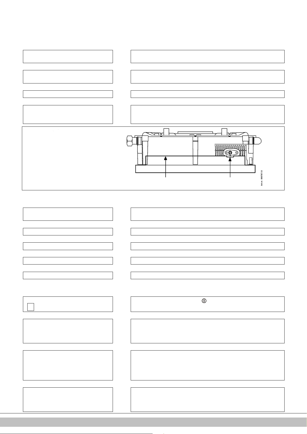
8.3 Sonstige Störungen
-
Stift muss
Prüfwerkzeug
berühren
Stift darf Prüfwerkzeug nicht
berühren
8.3.1 Kesselsteuerung macht beim Zünden Geräusche
Mögliche Ursachen: Lösung:
Der Gaszufuhrdruck ist zu hoch. Ja
Nein
Falsche Zündstrecke. Ja
Nein
Gas/Luft-Regelung nicht richtig konfiguriert. Ja Überprüfen Sie die Einstellung, siehe Gas/Luft-Regelung.
Nein
Schwacher Funken. Ja
Überprüfung der Zündstiftposition
Die Hausdrucksteuerung ist möglicherweise defekt. Wenden Sie sich an den
Energieversorger.
Prüfen Sie den Zündstiftabstand.
Ersetzen Sie den Zündstift.
Prüfen Sie die Zündstrecke.
Prüfen Sie das Zündkabel und/oder ersetzen sie es.
Ersetzen Sie die Zündvorrichtung am Gasblock. Ersetzen Sie den Zündstift.
8.3.2 Kesselsteuerung schwingt mit
Mögliche Ursachen: Lösung:
Der Gaszufuhrdruck ist zu niedrig. Ja
Die Hausdrucksteuerung ist möglicherweise defekt. Wenden Sie sich an den
Gasversorger.
Nein
Rückführung von Verbrennungsgasen. Ja Prüfen Sie den Verbrennungsgasabzug und die Luftzufuhr.
Nein
Gas/Luft-Regelung nicht richtig konfiguriert. Ja Überprüfen Sie die Einstellung, siehe Gas/Luft-Regelung.
Nein
Dichtung der Kesselsteuerung fehlerhaft. Ja Ersetzen Sie die Dichtung der Kesselsteuerung.
Nein
Kesselsteuerung defekt. Ja Ersetzen Sie die Kesselsteuerung.
8.3.3 Kein Heizen (ZH)
Mögliche Ursachen: Lösung:
Die Wartungsanzeige zeigt einen Bindestrich
(
) an. Der Kessel ist ausgeschaltet.
Ja
Nein
Raumthermostat/witterungsgeführte Regelung
nicht geschlossen oder fehlerhaft.
Ja
Nein
Pumpe läuft nicht. Anzeige zeigt 80 und 1 an. Ja
Nein
Keine Stromversorgung (24 V). Ja
Schalten Sie den Kessel mit der Taste ein.
Überprüfen Sie die Verdrahtung.
Überprüfen Sie den OpenTherm- und den Ein/Aus-Anschluss des Geräts.
Ersetzen Sie das Thermostat.
Ersetzen Sie die witterungsgeführte Regelung.
Prüfen Sie die Stromversorgung.
Überprüfen Sie Anschluss X2.
Setzen Sie einen Schraubendreher in den Schlitz der Pumpenwelle ein und drehen
Sie die Welle.
Ersetzen Sie die defekte Pumpe.
Ersetzen Sie die defekte Steuerung. Prüfen Sie, ob die Verdrahtung dem Schaltplan
entspricht.
Prüfen Sie den Anschluss X4.
Ersetzen Sie die defekte Steuerung.
Daikin Europe NV
45
Page 96

8.3.4 Leistung eingeschränkt
-
Mögliche Ursachen: Lösung:
Bei hoher Drehzahl ist die Leistung um mehr als
5% reduziert.
Ja
Überprüfen Sie das Gerät, den Siphon und das Abzugssystem auf
Verschmutzungen.
Reinigen Sie das Gerät, den Siphon und das Abzugssystem.
8.3.5 ZH erreicht nicht die richtige Temperatur
Mögliche Ursachen: Lösung:
Der Wasserdruck in der Installation ist zu
niedrig.
Nein
Die Einstellung des Raumthermostats ist falsch. Ja Überprüfen Sie die Einstellung und passen Sie sie ggf. an: Stellen Sie sie auf 0,1 A.
Nein
Die Temperatur ist zu niedrig eingestellt. Ja
Nein
Die Pumpe läuft nicht richtig. Die
Pumpeneinstellung ist zu niedrig.
Nein
Es fließt kein Wasser in der Installation. Ja
Nein
Die Kesselleistung ist nicht für die Installation
eingestellt.
Nein
Keine Wärmeübertragung aufgrund von
Verschmutzungen im Wärmetauscher/in der
Installation.
Ja Füllen Sie die Installation auf.
Erhöhen Sie die ZH-Temperatur. Siehe ZH-Bedienungsanleitung. Falls ein
Außentemperaturfühler vorhanden ist: Überprüfen Sie den Außentemperaturfühler
auf Kurzschluss und beheben Sie diesen ggf.
Ja Erhöhen Sie die Pumpeneinstellung oder ersetzen Sie die Pumpe.
Überprüfen Sie, ob Wasser durch die Installation fließen kann: Mindestens 2 oder 3
Radiatoren müssen eingeschaltet sein.
Ja Ändern Sie die Leistung. Siehe "Einstellung der maximalen ZH-Leistung".
Ja Spülen Sie den Wärmetauscher/die Installation auf der ZH-Seite aus.
8.3.6 Kein Warmwasser (nur gültig bei einem indirekt befeuerten Kessel)
Mögliche Ursachen: Lösung:
Die Wartungsanzeige zeigt einen Bindestrich
(
) an. Das Gerät ist ausgeschaltet.
Nein
3-Wege-Ventil nicht stromversorgt. Ja Prüfen Sie, ob die Verdrahtung dem Schaltplan entspricht.
Nein
Das 3-Wege-Ventil schaltet nicht. Ja Ersetzen Sie das 3-Wege-Ventil.
Nein
Speicherfühler/-thermostat nicht stromversorgt
(5 VDC).
Nein
Die Kesselsteuerung liefert kein Warmwasser:
Kesselfühler/-thermostat fehlerhaft.
Nein
Die Kesselsteuerung zündet nicht. Ja Siehe Kesselsteuerung zündet nicht.
Ja
Ja Prüfen Sie, ob die Verdrahtung dem Schaltplan entspricht.
Ja
Schalten Sie das Gerät mit der Taste ein.
Ersetzen Sie den Speicherfühler/das Kesselthermostat.
8.3.7 Warmwasser erreicht nicht die Soll-Temperatur (nur gültig für indirekt befeuerten Speicher)
Mögliche Ursachen: Lösung:
Die Speichertemperatur ist zu niedrig
eingestellt.
Ja Stellen Sie die Speichertemperatur ein. Siehe "Einstellungen und Anpassungen"
8.3.8 ZH-Installation bleibt ungewollt warm
Mögliche Ursachen: Ursache/Lösung:
Überprüfen Sie die Verdrahtung.
Raumthermostat/witterungsgeführte Regelung
fehlerhaft oder kurzgeschlossen.
Daikin Europe NV
Ja
Überprüfen Sie den OpenTherm- und den Ein/Aus-Anschluss des Geräts.
Ersetzen Sie das Thermostat.
Ersetzen Sie die witterungsgeführte Regelung.
46
Page 97

8.3.9 LED der A-Klasse-Pumpe blinkt abwechselnd rot/grün
Mögliche Ursachen: Lösung:
Zu hohe oder zu niedrige Netzspannung. Ja Prüfen Sie die Netzspannung.
Nein
Die Pumpentemperatur ist zu hoch. Ja Prüfen Sei die Wasser- und Umgebungstemperatur.
8.3.10 LED der A-Klasse-Pumpe blinkt rot
Mögliche Ursachen: Lösung:
Setzen Sie die Pumpe zurück, indem Sie das Gerät durch Drücken der Ein/AusTaste für mindestens 20 Sekunden ausschalten (Achtung: Falls die Pumpe auf
Pumpe gestoppt. Ja
"Kontinuierlich" eingestellt ist, kann die Pumpe nur durch Ziehen des Steckers aus
der Steckdose zurückgesetzt werden).
Ersetzen Sie die Pumpe.
Daikin Europe NV
47
Page 98

9 WARTUNG
Das Gerät und die Installation müssen von einem zertifizierten Monteur überprüft und ggf.
gereinigt werden.
VORSICHT
Arbeiten an gasführenden Teilen dürfen nur von einem
qualifizierten Monteur durchgeführt werden.
Überprüfen Sie nach Abschluss der Arbeiten die
Verbrennungsgas-führenden Teile auf Dichtheit.
Wenn das Gerät gerade in Betrieb war, können einige Teile
heiß sein.
9.1.1 Demontage
1. Schalten Sie das Gerät mit der Taste aus.
2. Entfernen Sie den Netzstecker aus der Steckdose.
3. Schließen Sie das Gasventil.
4. Öffnen Sie die Anzeigeabdeckung, lösen Sie die beiden Schrauben links und rechts
an der Anzeige und entfernen Sie dann die Frontabdeckung.
5. Warten Sie, bis das Gerät abgekühlt ist.
6. Lösen Sie die Überwurfmutter unten links am Verbrennungsgasrohr.
7. Schieben Sie das Gasrohr nach oben (1) mit einer Drehung nach links, bis das
Unterteil des Rohrs über die Verbindungsmuffe des Kondensatfangs hinausragt.
Ziehen Sie das Unterteil des Rohrs nach vorn (2) und entfernen Sie das Rohr, indem
Sie es nach links und unten drehen (3).
8. Heben Sie den Kondensatauffang aus dem Anschluss des Siphons (4) links heraus
und drehen Sie ihn mit dem Siphonanschluss nach rechts über die Kante der
unteren Wanne (5). Drücken Sie den Kondensatauffang an der Rückseite aus dem
Anschluss zum Wärmetauscher (6) und entfernen Sie ihn aus dem Gerät.
9. Entfernen Sie den Anschluss vom Lüfter und die Zündvorrichtung vom Gasblock.
10. Trennen Sie die Verbindungsmuffe unter dem Gasblock.
11. Lösen Sie die Passschrauben (Sechskantschlüssel) der Frontabdeckung und
entfernen Sie sie zusammen mit dem Gasblock und dem Lüfter von der Vorderseite
(achten Sie darauf, die Kesselsteuerung, die Isolierplatte, den Gasblock, das
Gasrohr und den Lüfter nicht zu beschädigen). Legen Sie die abgenommene
Frontabdeckung mit den Füßen horizontal auf einer ebenen Fläche ab.
12. Die Kesselsteuerung und die integrierte Isolierplatte erfordern keine Wartung (d. h.
sie müssen nicht gereinigt werden). Verwenden Sie daher niemals eine Bürste oder
Druckluft, um diese Teil zu reinigen, um so Staubentwicklung zu vermeiden.
9.1.2 Reinigen
1. Reinigen Sie die Unterseite des Wärmetauschers.
2. Reinigen Sie den Kondensatauffang mit Wasser.
3. Reinigen Sie den Siphon mit Wasser.
4. Reinigen Sie nur die Unterseite der Frontabdeckung.
VORSICHT
Die integrierte Isolierplatte und die Dichtung der
Kesselsteuerung enthalten Keramikfasern.
Daikin Europe NV
48
Page 99

9.1.3 Montage
03010078
03010083
1
2
3
4
5
6
7
8
9
10
11
Der Dichtungsring Vorplatte muss bei die Wartung ersetzt
werden.
Überprüfen Sie bei der Montage die übrige Dichtungen auf
Beschädigungen, Aushärtungen, Haarrisse, Brüche und/oder
Verfärbungen. Ersetzen Sie die Dichtungen gegebenenfalls.
Überprüfen Sie außerdem die richtige Lage.
1. Überprüfen Sie, dass sich zwischen dem Flansch der Passschrauben und
der Frontabdeckung eine dünne Schicht Keramikfett befindet.
Falls sich dort kein oder zu wenig Keramikfett befindet, muss dieses
aufgetragen werden (siehe Abbildung).
2. Überprüfen Sie, ob die Dichtung rund um die Frontabdeckung richtig
montiert wurde. Bringen Sie die Frontabdeckung des Wärmetauschers an
und sichern Sie diese mit den speziellen Passschrauben
(Sechskantschrauben). Ziehen Sie die Passschrauben gleichmäßig
kreuzweise manuell an (10 – 12 Nm). Die Reihenfolge zum Anziehen der
Schrauben ist in der Abbildung dargestellt.
Hinweis: Die Frontabdeckung in der Abbildung verfügt über 11
Passschrauben.
Die Frontabdeckung des EHOBG12ABV1 und EHOBG18ABV1 verfügt
über 9 Passschrauben.
3. Ziehen Sie die Schrauben der Kesselsteuerung gleichmäßig kreuzweise von
Hand an.
4. Bringen Sie die Gas-Verbindungsmuffe unter dem Gasblock an.
5. Bringen Sie den Anschluss am Lüfter und die Zündvorrichtung am Gasblock
an.
6. Bringen Sie den Kondensatauffang an, indem Sie ihn in den Auslassstumpf
des Switchers (1) mit dem Siphonanschluss vor dem unteren Fach
einschieben. Drehen Sie dann den Kondensatauffang nach links (2) und
drücken Sie ihn nach unten in den Siphonanschluss (3) ein. Stellen Sie
sicher, dass die Rückseite des Kondensatauffangs auf dem Steg an der
Rückseite des unteren Behälters (A) aufliegt.
7. Füllen Sie den Siphon mit Wasser und bringen Sie ihn am Anschluss unter
dem Kondensatauffang an.
8. Schieben Sie das Verbrennungsgasrohr mit der Oberkante rund um den
Verbrennungsgasadapter in die obere Abdeckung. Drehen Sie das Rohr
hierbei links herum. Setzen Sie das Unterteil in den Kondensatauffang ein,
ziehen Sie die Dichtung nach unten und ziehen Sie den Gelenkkopf rechts
herum an.
9. Öffnen Sie das Gasventil und überprüfen Sie die Gasanschlüsse unter dem
Gasblock und an der Montagehalterung auf Dichtheit.
10. Überprüfen Sie die Zentralheizung und die Wasserrohre auf Dichtheit.
11. Stecken Sie den Netzstecker in die Steckdose ein.
12. Schalten Sie das Gerät mit der Taste ein.
13. Überprüfen Sie die Frontabdeckung, den Anschluss des Lüfters an der
Frontabdeckung sowie die Verbrennungsgasrohr auf Dichtheit.
14. Überprüfen Sie die Gas/Luft-Regelung (siehe Abschnitt 7.7) und überprüfen
Sie den Gasanschluss am Gasblock auf Dichtheit.
15. Montieren Sie die Abdeckung und ziehen Sie die beiden Schrauben links
und rechts an der Anzeige fest. Schließen Sie dann die Anzeigeabdeckung.
16. Überprüfen Sie die Heizfunktion und die Warmwasserbereitstellung auf
ordnungsgemäße Funktionsweise.
49
Daikin Europe NV
Page 100

10 TECHNISCHE DATEN
Modellname EHOBG12ABV1 EHOBG18ABV1
Brennwertkessel Ja Ja
Niedertemperatur - Kessel Nein Nein
B1 – Kessel Nein Nein
Kombiheizgerät Nein Nein
ZH
Nennlast oberer Wert, Qn (Hs) kW 4,2 – 13,9 6,2 – 20,8
Nennlast unterer Wert, Qn (Hi) kW 3,8 – 12,5 5,6 – 18,7
Nennwert Leistung, Pn kW 4,1 –12,2 6,1 – 18,2
Max. ZH-Wasserdruck, PMS bar 3
Max. ZH-Wassertemperatur °C 90
Sonstige Daten
Gasverbrauch G25
Gasverbrauch G20
Gasverbrauch G31
Druckverlust des Geräts (ZH) mH20 Siehe Abschnitt 7.4
Max. Rauchgastemperatur °C 70 70
Rauchgas-Massenfluss (max.) g/s 5,8 8,7
Verfügbarer Lüfterdruck Pa 75 75
NOx-Klasse 6 6
NOx mg/kWh 19 38
P1 bei 30% der Wämenennleistung (30/37) kW 4,1 6,1
P4 bei Wärmenennleistung (80/60) kW 12,2 18,2
ɳ 1, Effizienz bei P1
ɳ 4, Effizienz bei P4
Wärmeverlust im Bereitschaftszustand (Pstby)
Elektrische Daten
Netzspannung V 230
Schutzart IP IPX4D (B23, B33 = IP20)
Aufgenommene Leistung: Volllast W 80
Aufgenommene Leistung: Standby W 2
Hilfsstromverbrauch bei Volllast (elmax) kW 0,040 0,035
Hilfsstromverbrauch bei Teillast (elmin) kW 0,015 0,015
Hilfsstromverbrauch im Bereitschaftszustand (Psb) kW 0,002 0,002
Installationsabmessungen und Gewicht
Höhe mm 590
Breite mm 450
Tiefe mm 240
Gewicht kg 30
(1)
Gasart
(EN 15502) B23; B33; C13x; C33x; C43x; C53x; C63x; C83x: C93x
Bestimmungsland Gerätekategorie (EN437) Gasart
IT II2H3P G20, 20 mbar, G31: 37 mbar
FR II2Esi3P G20, 20 mbar, G31: 37 mbar
BE I2E(S) G20, 20 mbar, G25: 25 mbar
PL II2E3P G20, 20 mbar, G31: 37 mbar
DE II2ELL3P G20, 20 mbar, G25: 20 mbar, G31: 50 mbar
(1)
G20 – Erdgas E/H
G25 – Erdgas LL/L
G31 – Flüssiggas Propan
(1)
m3/Std. 0,42 – 1,50 0,67 – 2,25
(1)
m3/Std. 0,36 – 1,30 0,58 – 1,94
(1)
m3/Std. 0,14 – 0,49 0,22 – 0,74
% 98,1 97.3
% 87,9 87,7
kW 0,037 0,037
(1)
und Nennanschlussdruck (EN 437)
Daikin Europe NV
50
 Loading...