

Daikin DPS012, DPS015, DPS004, DPS016, DPS018 Installation And Maintenance Manual
...
Installation and Maintenance Manual IM 1125-7
Group: Applied Air Systems
Part Number: IM 1125
Date: November 2015
Rebel™ Commercial Packaged
Rooftop Systems
Heating and Cooling
Models DPS003 – 028A
R-410A Refrigerant
MicroTech® III Unit Controller
Energy Recovery Wheel
3–6 tons
16–28 tons
Shown with Energy Recovery
7–15 tons
Shown with Energy Recovery

Table of ConTenTs
Introduction.............................................3
General Information .....................................3
Unit Nameplate......................................... 3
Hazard Identication Information ...........................3
Mechanical Installation ...................................4
Installer Responsibilities..................................4
Receiving Inspection ....................................4
Service Clearance ......................................4
Ventilation Clearance ....................................4
Overhead Clearance ....................................6
Roof Curb Assembly and Installation ........................6
Rigging and Handling ................................... 10
Unit Piping - Condensate Drain Connection.................. 12
Damper Assemblies ....................................12
Cabinet Weather Protection ..............................13
Installing Ductwork .....................................13
Electrical Installation . . . . . . . . . . . . . . . . . . . . . . . . . . . . . . . . . . . . 15
Pre-Construction ......................................15
Refrigeration System ....................................19
Piping System ........................................19
DPS 003–015 Component Description .....................21
DPS 016–028 Ton Component Description ..................27
VFD Compressor Operation – DPS 016–028 ................29
Variable Speed Scroll Compressor.........................33
Optional Modulating Hot Gas Reheat....................... 36
Modulating Hot Gas Reheat ............................. 36
Optional Electric Heat ...................................39
Electric Heater Design ..................................39
Optional Gas Heat ......................................40
Daikin Tubular Heater Series .............................40
Gas Furnace Design ...................................40
Gas Heating Capacity Data ..............................41
DPS 003–015 Sequence of Operation ...................... 48
DPS 016–028 Sequence of Operation .....................49
Start-Up Procedures.................................... 50
Operating Procedures ..................................51
DPS 003–015 (only) Ignition Control Module for
Staged Gas Furnace ...................................52
DPS 003–015 (only) Ignition Control Module for
Modulating Gas Furnace ................................53
DPS 003–015 (only) Gas Furnace Ignition and Control
Troubleshooting .......................................54
VB-1200 Trouble Shooting Guide..........................54
DPS 016–028 Gas Furnace Ignition Troubleshooting ..........60
Optional Hot Water Heat .................................65
Hot Water Heater Design ................................65
Optional Energy Recovery Wheel..........................66
System Description ....................................66
Optional Outdoor Air Monitor .............................69
Thermal Dispersion Airow Measurement Technology..........69
ECM Motor.............................................74
Table of ConTenTs
Unit Options ...........................................76
Economizer Enthalpy Control.............................76
External Time Clock ....................................76
Exhaust Fan Option ....................................76
Proof-of-Airow and Dirty Filter Switch...................... 76
Duct High Pressure Limit ................................76
Convenience Receptacle (Field Powered) ................... 77
Convenience Receptacle (Unit Powered) ...................77
Wiring Diagrams........................................78
Sequence of Operation ..................................90
Operating States ......................................90
Mechanical Cooling .................................... 91
Economizer ..........................................91
Preparing the Unit for Start Up ............................92
Pre-Start of Unit .......................................92
Spring Isolated Fans ...................................92
Servicing Control Panel Components ......................93
Power-Up ............................................93
Fan Start-Up..........................................93
Check, Test and Start Procedures .........................94
Economizer Start-Up ...................................94
Compressor Start-Up ...................................94
Set Up for Optimum Control .............................. 95
Air Balancing .......................................95
Energy Recovery Wheel................................. 96
Final Control Settings ...................................97
Final Control Settings ................................... 97
Maintaining Control Parameter Records ....................97
Maintenance ...........................................98
Performing Service Maintenance ..........................98
Planned Maintenance................................... 98
Unit Storage ..........................................98
Periodic Service and Maintenance.........................99
Refrigerant Charge....................................100
Servicing Refrigerant Sensors or Switches ............... 101
Servicing Optional Electric Heater .................... 101
Servicing the Compressor Ground Fault Interrupter ..........101
Phase Voltage Monitor (PVM) ...........................101
Cleaning Option E Coated Coils .........................102
Service and Warranty Procedures ........................103
Replacement Parts....................................103
Scroll Compressor ....................................103
In-Warranty Return Material Procedure ....................103
Warranty Registration Form.............................104
Quality Assurance Survey Report ........................108
Appendix – Keypad/Display Menu Structure................ 11 0
IM 1125-7 • REBEL ROOFTOPS 2 www.DaikinApplied.com
General Information
This manual provides general information about the “A”
vintage Daikin Rebel Commercial Packaged Rooftop Unit,
model DPS. In addition to an overall description of the unit,
it includes mechanical and electrical installation procedures,
commissioning procedures, sequence of operation information,
and maintenance instructions.
The MicroTech® III rooftop unit controller is equipped on
“A” vintage rooftop units. For a detailed description of the
MicroTech III components, input/output congurations, eld
wiring options and requirements, and service procedures,
see OM 1141. For operation and information on using and
programming the MicroTech III unit controller, refer to the
appropriate operation manual (see Table 1).
For a description of operation and information on using
the keypad to view data and set parameters, refer to the
appropriate program-specic operation manual (see Table 1).
InTroduCTIon
Unit Nameplate
The unit nameplate is located on the outside of the main
control box door. It includes the unit model number, serial
number, electrical characteristics, and refrigerant charge.
Hazard Identication Information
DANGER
Dangers indicate a hazardous situation which will result
in death or serious injury if not avoided.
WARNING
Warnings indicate potentially hazardous situations,
which can result in property damage, severe personal
injury, or death if not avoided.
InTroduCTIon
Table 1: Program Specic Unit Operation Literature
Rooftop unit control conguration
BACnet IP Comm Module IM 916
BACnet® Integration IM 917
LonWorks® Integration IM 918
DPS Unit Controller Discharge
Air Control (VAV or CAV)
Space Comfort Control (SCC)
Rebel Quick Start Guide OM 1164
Manual
bulletin number
OM 1141
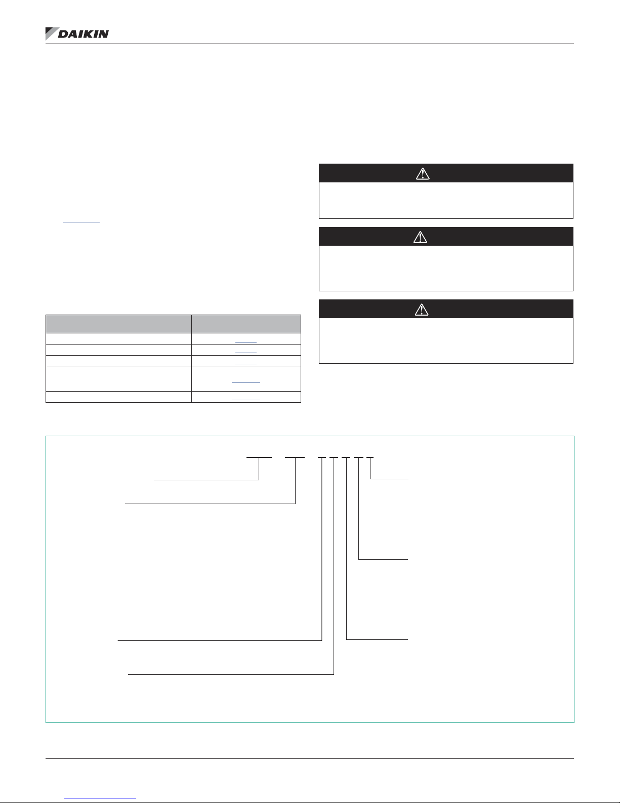
Nomenclature (DPS 003–028)
DPS – 010 – A H H G 4
Daikin Packaged System
Nominal capacity
003 = 3 tons 016 = 16 tons
004 = 4 tons 018 = 18 tons
005 = 5 tons 020 = 20 tons
006 = 6 tons 025 = 25 tons
007 = 7.5 tons 028 = 28 tons
010 = 10 tons
012 = 12 tons
015 = 15 tons
CAUTION
Cautions indicate potentially hazardous situations,
which can result in personal injury or equipment damage
if not avoided.
Line voltage
2 = 208 volt power supply
3 = 230 volt power supply
4 = 460 volt power supply
5 = 575 volt power supply
Heat medium
Y = None (cooling only)
G = Natural gas heat
E = Electric heat
W = Hot water heat
Design vintage
A = Vintage 1
Cooling efciency
H = High (exceeds ASHRAE 92)
www.DaikinApplied.com 3 IM 1125-7 • REBEL ROOFTOPS
Unit style
C = Cooling only
H = Heat pump
M = Cooling-only microchannel

Installer Responsibilities
MeChanICal InsTallaTIon
MeChanICal InsTallaTIon
Service Clearance
CAUTION
Sharp edges on sheet metal and fasteners can cause
personal injury. This equipment must be installed,
operated, and serviced only by an experienced
installation company and fully trained personnel.
The installation of this equipment shall be in accordance
with the regulations of authorities having jurisdiction and all
applicable codes. It is the responsibility of the installer to
determine and follow the applicable codes.
Receiving Inspection
When the equipment is received, all items should be carefully
checked against the bill of lading to be sure all crates and
cartons have been received. If the unit has become dirty
during shipment (winter road chemicals are of particular
concern), clean it when received.
All units should be carefully inspected for damage when
received. Report all shipping damage to the carrier and le a
claim. In most cases, equipment is shipped F.O.B. factory and
claims for freight damage should be led by the consignee.
Before unloading the unit, check the unit nameplate to make
sure the voltage complies with the power supply available.
CAUTION
Location. Care should be taken for the installation
location to minimize snow drifts on the outdoor coil.
Allow service clearances as approximately indicated in Figure
1. Also, Daikin recommends providing a roof walkway to the
rooftop unit as well as along each side of the unit that provides
access to most controls and serviceable components.
Refer to NEC and local for minimum clearances around the
unit and control panel.
Ventilation Clearance
Below are minimum ventilation clearance recommendations.
The system designer must consider each application and
provide adequate ventilation. If this is not done, the unit may
not perform properly.
Unit(s) Surrounded by a Screen or a Fence:
1. The bottom of the screen or fence should be at least 1 ft.
(305 mm) above the roof surface.
2. The distance between the unit and a screen or fence
should be as described in Figure 1.
3. The distance between any two units within a screen or
fence should be at least 120" (3048 mm).
Unit(s) Surrounded by Solid Walls:
1. If there are walls on one or two adjacent sides of the unit,
the walls may be any height. If there are walls on more
than two adjacent sides of the unit, the walls should not
be higher than the unit.
2. The distance between the unit and the wall should be at
least 96" (2438 mm) on all sides of the unit.
3. The distance between any two units within the walls
should be at least 120" (3048 mm).
Do not locate outside air intakes near sources of contaminated air.
If the unit is installed where windy conditions are common,
install wind screens around the unit, maintaining the
clearances specied (see Figure 1). This is particularly
important to maintain adequate head pressure control when
mechanical cooling is required at low outdoor air temperatures.
IM 1125-7 • REBEL ROOFTOPS 4 www.DaikinApplied.com

Figure 1: Service Clearances
MeChanICal InsTallaTIon
Small Cabinet
003—006
Filter
Access
60.00
(1524 mm)
Plenum Discharge,
Electric Heat &
Supply Fan Access
Large Cabinet
016—028
Exhaust
Fan Access
Outdoor Air
Control
Panel
Access
Hood
50.00
(1270 mm)
48.00
(1219 mm)
21.00 (533 mm)
Gas
59.2"
(1504 mm)
36.00
(914 mm)
Medium Cabinet
007—015
Filter
Access
60.00
(1524 mm)
Supply Fan
Access
Exhaust
Fan Access
Outdoor Air
Control
Panel
Access
Hood
50.00
(1270 mm)
48.00
(1219 mm)
17.00 (431 mm)
Gas
59.2"
(1504 mm)
36.00
914 mm)
www.DaikinApplied.com 5 IM 1125-7 • REBEL ROOFTOPS

MeChanICal InsTallaTIon
Overhead Clearance
1. Unit(s) surrounded by screens or solid walls must have
no overhead obstructions over any part of the unit. For
heat pump models overhead obstructions could allow the
formation of dangerous ice cycles.
2. The area above the condenser must be unobstructed in
all installations to allow vertical air discharge.
3. The following restrictions must be observed for overhead
obstructions above the air handler section:
a. There must be no overhead obstructions above the
furnace ue, or within 9" (229 mm) of the ue box.
b. Overhead obstructions must be no less than 96"
(2438 mm) above the top of the unit.
c. There must be no overhead obstructions in the areas
above the outside air and exhaust dampers that are
farther than 24" (610 mm) from the side of the unit.
Roof Curb Assembly and Installation
WARNING
Mold can cause personal injury. Some materials such
as gypsum wall board can promote mold growth when
damp. Such materials must be protected from moisture
that can enter units during maintenance or normal
operation.
Locate the roof curb and unit on a portion of the roof that can
support the weight of the unit. The unit must be supported to
prevent bending or twisting of the machine.
If building construction allows sound and vibration into
the occupied space, locate the unit over a non-critical
area. It is the responsibility of the system designer to
make adequate provisions for noise and vibration in the
occupied space.
Install the curb and unit level to allow the condensate drain to
ow properly and allow service access doors to open and close
without binding.
The gasketed top surface of the curb seals against the unit
when it is set on the curb. These anges must not support
the total weight of the duct work. See Installing Ductwork on
page 13 for details on duct connections. It is critical that
the condensate drain side of the unit be no higher than the
opposite side.
Assembly Instructions
Assembly of a typical roof curb is shown in Figure 2, Figure 3
on page 8 and Figure 4 on page 9.
1. Set curbing parts A thru G per dimensions shown over roof
opening or on a level surface. Note location of supply air
opening. Check alignment of all mating screw holes.
2. Screw curbing parts together using fasteners provided.
Leave all screws loose until curb is checked to be square.
3. Square entire curbing assembly and securely tighten all
screws.
4. Position curb assembly over roof openings. Curb must
be level within 0.25 inches from side to side and 1.50
inches over its length. Check that top surface of curb is
at with no bowing or sagging.
5. Weld curb assembly in place. Caulk all seams watertight.
Remove backing from 0.25 × 1.50 wide gasket and apply
to surfaces shown by crosshatching.
6. Check that electrical connections are coordinated.
IM 1125-7 • REBEL ROOFTOPS 6 www.DaikinApplied.com

Figure 2: Roof Curb Assembly (DPS 003—006)1
DPS 003–006 Roofcurb with ERW Certi ed Drawing
McQuay International certi es that its equipment will conform to this drawing and McQuay’s
published speci cations, subject to its published warranty. Purchaser must determine that the
equipment is t and suf cient for the job speci cations. No change to this drawing may be made
unless approved in writing by McQuay. www.DaikinMcQuay.com © 2012 McQuay International
Model: DPS
Date:
Unit Tag:
Units: Sheet: __ of __
Curb Detail
A–A
2"×4"
Nailer
A A
2.0"
Typ.
14.0"
or
24.0"
4.0"
3.9
28.55
Inside
9.69
Inside
28.69
Inside
44.38
Inside
76.0
Inside
19.1
9.5
Inside
18.5
Supply
Opening
Return
Opening
Electrical
Entrance
47.05
2.0
3.9
6.4
LEFT SIDE
G
28.69
INSIDE
B
MeChanICal InsTallaTIon
BACK SIDE
D
9.84
INSIDE
SUPPLY AIR
A
H
RETURN AIR
E
F
28.76
INSIDE
C
61.50
RIGHT SIDE
FRONT SIDE
44.24
9.64
INSIDE
NOTE: 1. Check submittal drawing for gas/water/electrical/supply/return air opening
Horizontal above the roof gas connection only
Standard Roof Curb – Small Cabinet
2.0
9.5
Inside
19.1
Return
Opening
44.38
Inside
Supply
Opening
28.55
Inside
Roof Curb for ERW – Small Cabinet
57.5
Inside
3.9
6.4
Electrical
Entrance
3.9
28.69
Inside
www.DaikinApplied.com 7 IM 1125-7 • REBEL ROOFTOPS
9.69
Inside
A A
Curb Detail
14.0"
or
24.0"
A–A
2.0"
Typ.
4.0"
2"×4"
Nailer
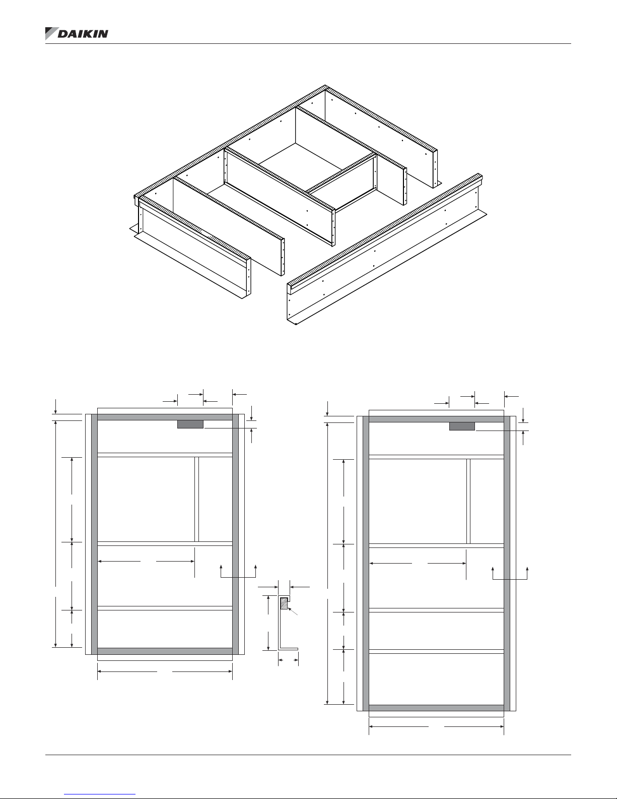
Figure 3: Roof Curb Assembly (DPS 007–015)1
DPS 007–012 Roofcurb with ERW Certi ed Drawing
McQuay International certi es that its equipment will conform to this drawing and McQuay’s
published speci cations, subject to its published warranty. Purchaser must determine that the
equipment is t and suf cient for the job speci cations. No change to this drawing may be made
unless approved in writing by McQuay. www.DaikinMcQuay.com © 2012 McQuay International
Model: DPS
Date:
Unit Tag:
Units: Sheet: __ of __
Curb Detail
A–A
2"×4"
Nailer
A A
2.0"
Typ.
4.0"
14.0"
or
24.0"
34.88
Inside
48.38
Inside
101.5
Inside
13.5
Inside
30.5
Inside
Supply
Opening
Return
Opening
Electrical
Entrance
20.0
24.25
2.0
3.4
6.9
8.8
MeChanICal InsTallaTIon
LEFT SIDE
BACK SIDE
A
SUPPLY
B
AIR
E
E
F
RETURN
AIR
FRONT SIDE
A
D
C
RIGHT SIDE
NOTE: 1. Check submittal drawing for gas/water/electrical/supply/return air opening
Horizontal above the roof gas connection only
Standard Roof Curb – Medium Cabinet
2.0
30.5
Inside
Supply
Opening
Electrical
Entrance
8.8
6.9
3.4
Roof Curb for ERW – Medium Cabinet
81.5
Inside
IM 1125-7 • REBEL ROOFTOPS 8 www.DaikinApplied.com
24.25
13.5
Inside
34.88
Inside
Return
Opening
48.38
Inside
A A
Curb Detail
14.0"
or
24.0"
A–A
2.0"
Typ.
4.0"
2"×4"
Nailer

Figure 4: Roof Curb Assembly (DPS 016–028)1
LEFT SIDE
B
RETURN
AIR
D
D
SUPPLY
AIR
E
MeChanICal InsTallaTIon
BACK SIDE
A
E
F
C
A
RIGHT SIDE
FRONT SIDE
NOTE: 1. Check submittal drawing for gas/water/electrical/supply/return air opening
2. Horizontal above the roof gas connection only
3. All dimensions in inches
Standard Roof Curb – Large Cabinet
Roof Curb for ERW – Large Cabinet
www.DaikinApplied.com 9 IM 1125-7 • REBEL ROOFTOPS
Rigging and Handling
WARNING
Only trained and qualified personnel should be allowed
to rig loads or operate load rated cranes and/or hoist
assemblies. Do not use a forklift to lift or maneuver the
unit. Failure to use a load rated crane or hoist assembly
to lift or maneuver the unit can cause severe personal
injury and property damage.
WARNING
Use all lifting points. Improper lifting can cause property
damage, severe personal injury, or death.
CAUTION
Lifting points may not be symmetrical to the center
of gravity of the unit. Ballast or unequal cable lengths
may be required.
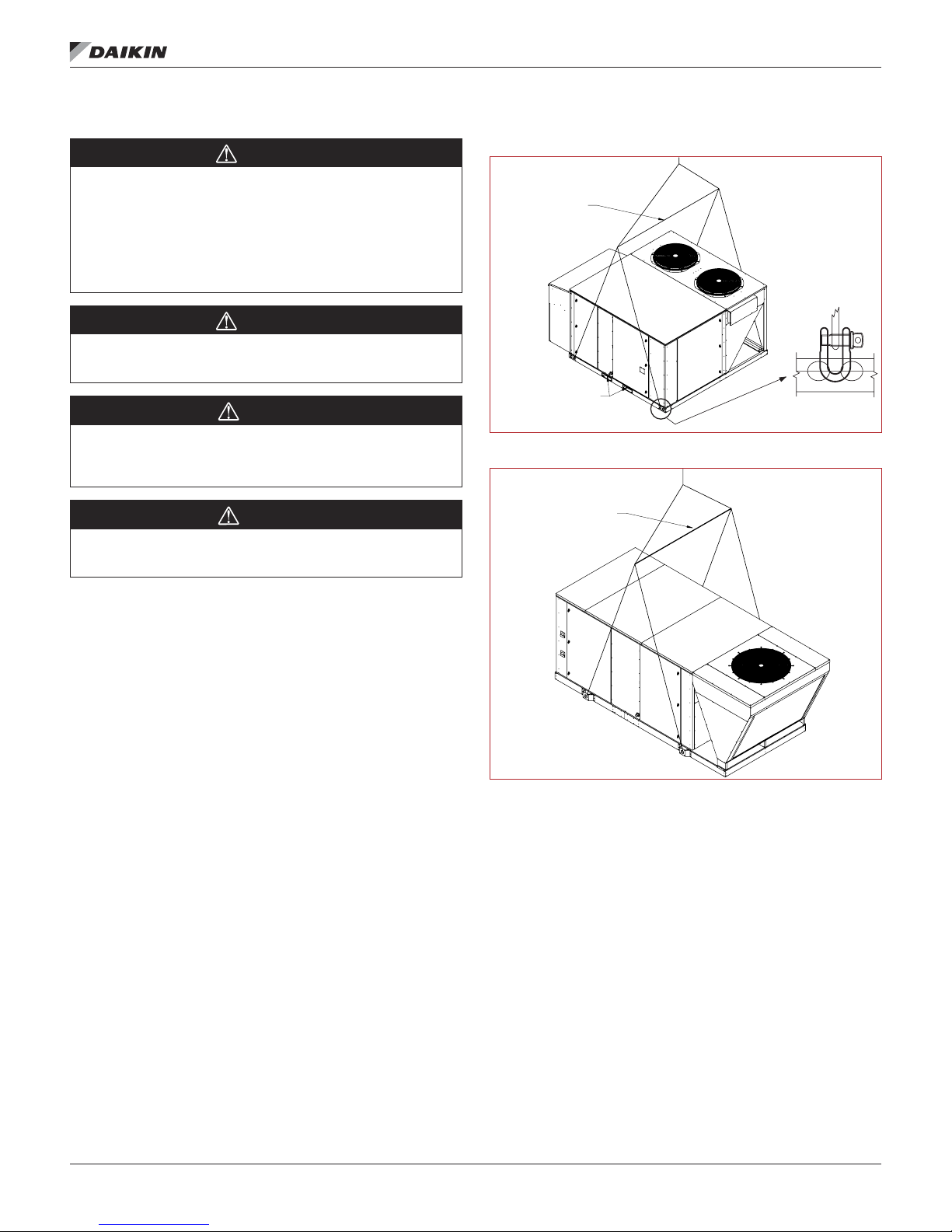
Figure 5: Rigging Label 003–015
LIFT ONLY AS SHOWN
USE SPREADER BAR
REMOVE THE FORKLIFT
CHANNELS BEFORE
SETTING THE UNIT ON
THE ROOF CURB
Figure 6: Rigging Label 016–028
LIFT ONLY AS SHOWN
MeChanICal InsTallaTIon
CAUTION
Unit is equipped with fork slot reenforcement pieces.
These need to be removed before unit is set on the curb.
Rigging holes for shackles are integral on the unit base. Use
four independent lines, securing one end of a line to a
unit base lifting point and the other end of the line to an
associated spreader bar lifting point. Figure 5 and Figure 6
are examples of instruction labels shipped with each unit.
Use spreader bars to prevent damage to the unit cabinet. Avoid
twisting or uneven lifting of the unit. The cable length from the
bracket to the hook should always be longer than the distance
between the outer lifting points.
If the unit is stored at the construction site for an intermediate
period, take these additional precautions:
1. Support the unit well along the length of the base rail.
2. Level the unit (no twists or uneven ground surface).
3. Provide proper drainage around the unit to prevent
ooding of the equipment.
4. Provide adequate protection from vandalism, mechanical
contact, etc.
5. Securely close the doors.
6. Cover the supply and return air openings.
USE SPREADER BAR
IM 1125-7 • REBEL ROOFTOPS 10 www.DaikinApplied.com

MeChanICal InsTallaTIon
Table 2: Physical Data—Unit Weights DPS 003 through 028
Model
003 004 005 006 007 010 012 015
Weight (lbs.)
Base Weight
1
1000 1000 1025 1058 1600 1600 1600 1763
Heat pump 1030 1030 1058 1058 1660 1660 1660 1823
Electric Heat 45 45 45 45 100 100 100 100
Hot Water 2 Row 11 11 11 16.5 30 30 30 30
Hot Water 1 Row 32 32 32 20 31 31 31 31
Gas Heat 75 75 63 93 186 186 186 186
Hot Gas Re-heat 8 8 12 12 28 31 31 31
Economizer 163 163 163 163 308 308 308 308
High capacity coil 105 105 105 105 215 215 215 215
Energy Wheel Weight Adds (lbs.)
100% OA 160 160 160 160 300 300 300 300
Mixed Air 175 175 175 175 250 250 250 250
1. Includes standard cooling coil
Small Cabinet Medium Cabinet
Model
Base Weight (in lbs.) 2,465 2,575 2,700
Heat Pump — — — — —
Electric Heat 228
1-row 60
Hot Water Heat
Gas Heat
Hot Gas Reheat 30
Economizer 500
ERW – Small 350
ERW – Large 400
Indoor Fan
Indoor Fan Motors
Exhaust Fan 250
2-row 100
3-row 140
016 018 020 025 028
300 175
450 225
600 275
16" 100
20" 150
24" 260
1 36
1.5 41
2 40
3 69
5 84
7.5 11 5
10 128
15 211
20 225
Large Cabinet
Size 3–15 Fan Weights (lbs.)
12 (in) 87
14 (in) 91
16 (in) 115
18 (in) 87
20 (in) 91
22 (in) 115
Curb Weights (lbs.) 14" 24"
003—006 156 230
007—015 200 295
016—028 566 657
Table 3: Refrigerant Charge
Unit Size
3 10.5 12.9 12.0 14.4
4 11.1 13.5 12.6 15.0
5 15.3 18.2 16.8 19.7
6 15.3 18.2 16.8 19.7
7.5 11.0 17.3 26.0 31.2
10 34.0 39.8 40.0 45.8
12 34.0 39.8 40.0 45.8
15 37.0 43.8 42.0 47.8
16 37.0
18 37.0
20 37.0
25 35.5
28 35.5
Cooling Model Heat Pump Model
Standard Unit
Standard Unit
w/ MHGRH
Standard Unit
Consult Factory
Standard Unit
w/ MHGRH
www.DaikinApplied.com 11 IM 1125-7 • REBEL ROOFTOPS
Static Pressure (P)
Actuator
MeChanICal InsTallaTIon
Unit Piping - Condensate Drain Connection
WARNING
Drain pans must be cleaned periodically. Material in
uncleaned drain pans can cause disease. Cleaning
should be performed by qualified personnel.
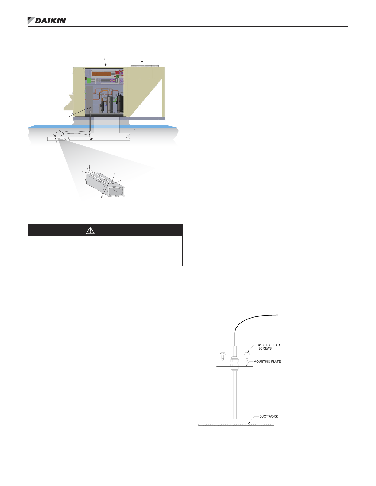
The unit is provided with a condensate drain connection, a 3/4"
male NPT for 003–015 units and a 1" male NPT for 016–028
units. For proper drainage, level the unit and drain pan side to
side and install a P-trap.
Figure 7 shows the layout of the condensate drain connection.
The distance from the drain pan outlet to the horizontal run of
the P-trap should be a distance of twice the static pressure in
the drain pan.
Example: If the static pressure as measured in the drain pan
is 1.5", then the distance between the drain outlet and the
horizontal run should be 3".
Draining condensate directly onto the roof may be acceptable;
refer to local codes. Provide a small drip pad of stone, mortar,
wood, or metal to protect the roof against possible damage.
If condensate is piped into the building drainage system, pitch
the drain line away from the unit a minimum of 1/8" per foot.
The drain line must penetrate the roof external to the unit.
Refer to local codes for additional requirements. Sealed drain
lines require venting to provide proper condensate ow.
Periodically clean to prevent microbial growth/algae buildup
from plugging the drain and causing the drain pan to overow.
Clean drain pans to prevent the spread of disease. Cleaning
should be performed by qualied personnel.
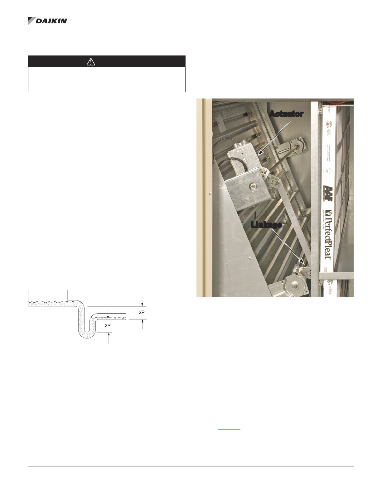
Damper Assemblies
The optional damper assemblies described in this section
are ordered with factory-installed actuators and linkages.
The following sections describe the operation and linkage
adjustment of the factory option.
Figure 8: Damper Assembly
Linkage
Figure 7: Condensate Drain Connection
at the Drain Pan
Economizer Dampers
As the single actuator modulates, the outside air dampers
open, the return air dampers close, and the exhaust air exits
the unit through the gravity relief dampers.
The economizer comes with manually adjustable linkage (Figure
8). The damper is set so that the crank-arm moves through
a 90-degree angle to bring the economizer dampers from full
open to full close. Mechanical stops are placed in the crank-arm
mounting bracket. Do not remove stops. Driving the crank-arm
past the stops results in damage to the linkage or damper.
Outdoor Air Dampers (0% to 30%)
These dampers are intended to remain at a xed position during
unit operation, providing fresh air quantities from 0 to 30% of the
total system airow, depending on the damper setting.
The damper position may be set at the unit controller keypad
(refer to OM 1141 for further detail). During unit operation, the
damper is driven to the position set at the unit controller. During
the OFF cycle, the damper is automatically closed.
IM 1125-7 • REBEL ROOFTOPS 12 www.DaikinApplied.com

MeChanICal InsTallaTIon
Cabinet Weather Protection
CAUTION
Transportation, rigging, or maintenance can damage
the unit’s weather seal. Periodically inspect the unit
for leakage. Standing moisture can promote microbial
growth, disease, or damage to the equipment and
building.
This unit ships from the factory with fully gasketed access
doors and cabinet caulking to provide weather resistant
operation. After the unit is set in place, inspect all door gaskets
for shipping damage and replace if necessary.
Protect the unit from overhead runoff from overhangs or other
such structures.
Installing Ductwork
WARNING
Mold can cause personal injury. Materials such as
gypsum wall board can promote mold growth when
damp. Such materials must be protected from moisture
that can enter units during maintenance or normal
operation.
On vertical-supply/vertical-return units, if a Daikin roof curb
is not used, the installing contractor should make an airtight
connection by attaching eld fabricated duct collars to the
bottom surface of the unit’s duct opening. Do not support the
total weight of the duct work from the unit.
Use exible connections between the unit and ductwork to
avoid transmission of vibration from the unit to the structure.
To minimize losses and sound transmission, design duct work
per ASHRAE and SMACNA recommendations.
Where return air ducts are not required, connect a sound
absorbing T or L section to the unit return to reduce noise
transmission to the occupied space.
Ductwork exposed to outdoor conditions must be built in
accordance with ASHRAE and SMACNA recommendations
and local building codes.
Table 4: AHRI CFM Ratings
Unit Size AHRI Rated CFM Unit Size AHRI Rated CFM
3 1140 15 4690
4 1550 16 Consult Factory
5 1810 18 Consult Factory
6 2310 20 7315
7.5 2885 25 8180
10 3850 28 8200
12 4620
Installing Duct Static Pressure Sensor Taps
For all VAV units, duct static pressure taps must be eld
installed and connected to the static pressure sensor 1 (SPS1)
in the unit. Sensor SPS1 is standard on VAV units and is
located in the main control panel.
Carefully locate and install the duct static pressure sensing
tap. Improperly locating or installing the sensing tap causes
unsatisfactory operation of the entire variable air volume
system. Below are pressure tap location and installation
recommendations. The installation must comply with local code
requirements.
1. Install a tee tting with a leak-tight removable cap in each
tube near the sensor tting. This facilitates connecting a
manometer or pressure gauge if testing is required.
2. Use different colored tubing for the duct pressure (HI)
and reference pressure (LO) taps, or tag the tubes.
Daikin recommends 3/16" ID tubing.
3. Locate the duct pressure (HI) tap near the end of a long
duct to ensure that all terminal box take-offs along the
run have adequate static pressure.
4. Locate the duct tap in a nonturbulent ow area of the
duct. Keep it several duct diameters away from take-off
points, bends, neckdowns, attenuators, vanes, or other
irregularities.
5. Use a static pressure tip (Dwyer A302 or equivalent) or
the bare end of the plastic tubing for the duct tap. (If the
duct is lined inside, use a static pressure tip device.)
6. Install the duct tap so that it senses only static pressure
(not velocity pressure). If a bare tube end is used,
it must be smooth, square (not cut at an angle) and
perpendicular to the airstream (see Figure 10).
7. Locate the reference pressure (LO) tap near the duct
pressure tap within the building. If the tap is not connected
to the sensor, unsatisfactory operation will result.
8. Route the tubes through the curb and feed them into the
unit through the knockout in the bottom of the control
panel (see Figure 9). Connect the tubes to appropriate
barbed ttings (on SPS1) in the control panel. (Fittings
are sized to accept 3/16" ID tubing.)
Figure 9: Typical Wiring Chase, Size 007–015 shown
Field
Wiring
Block
Behind
Panel
Utility
Chase
www.DaikinApplied.com 13 IM 1125-7 • REBEL ROOFTOPS
MeChanICal InsTallaTIon
Figure 10: Duct Static Pressure Sensing Tubing Installation
Condenser Sec tion
Roof
Ductwork
(RemoteLocation)
Tubing Extends
Through Approx.3/16"
SPS1
LO Line
HI Line
Remote Sense Po int
To Sensor
LO Input
Main ControlPanel
To Sensor
HI Input
PressureSensing
Tubing
Rubber
Grommet
Installing Building Static Pressure Sensor Taps
CAUTION
Fragile sensor fittings. If you must remove tubing
from a pressure sensor fitting, use care. Do not use
excessive force or wrench the tubing back and forth to
remove or the fitting can break off and damage sensor.
If a unit has building static pressure control capability, you
must eld install and connect static pressure taps to the static
pressure sensor SPS2 in the unit. This sensor is located at the
bottom of the main control panel next to SPS1.
Carefully locate and install the two static pressure sensing
taps. Improper location or installation of the sensor taps causes
unsatisfactory operation. Below are pressure tap location and
installation recommendations for both building envelope and
lab, or “space within a space” pressure control applications.
The installation must comply with local code requirements.
3. Locate the building tap so it is not inuenced by any
source of moving air (velocity pressure). These sources
may include air diffusers or outside doors.
4. Route the building tap tube through the curb and feed
it into the unit through the knockout in the bottom of the
control panel (refer to Figure 9). Connect the 3/16" ID
tube to the (high) tting for sensor SPS2.
5. Locate the reference pressure (low) tap on the roof.
Keep it away from the condenser fans, walls, or anything
else that may cause air turbulence. Mount it high
enough above the roof so it is not affected by snow. Not
connecting the reference tap to the sensor results in
unsatisfactory operation.
6. Use an outdoor static pressure tip (Dwyer A306 or
equivalent) to minimize the adverse effects of wind.
Place some type of screen over the sensor to keep out
insects. Loosely packed cotton works well.
7. Route the outdoor tap tube out of the main control panel
through a small eld-cut opening in the upright. Seal the
penetration to prevent water from entering. Connect the
3/16" ID tube to the (low) tting for sensor SPS2.
Discharge Air Temperature Sensor
The discharge air temperature sensor must be installed in the
discharge air duct, downstream of the rooftop unit. Locate the
sensor in a location that closely approximates the average
duct temperature. To avoid the effects of radiation, the sensor
should not be in the line-of-sight of a gas furnace or electric
heater. Generally, locate sensor in the center of a duct wall,
5′ – 10′ from unit opening to allow for air mixing. Do not mount
down stream of VAV boxes or other dampers.
Installation: Drill 7/8" diameter hole in duct, insert sensor probe
and secure plate to duct with 2 – #10 screws. Be sure to apply
gasket or silicone sealant to back of mounting plate prior to
screwing plate to the duct to create an air-tight seal.
Figure 11: Discharge Air Temperature Sensor Installation
Building Pressurization Applications
1. Install a tee tting with a leak-tight removable cap in each
tube near the sensor tting. This facilitates connecting a
manometer or pressure gauge if testing is required.
2. Locate the building pressure (high) tap in the area that
requires the closest control. Typically, this is a ground
level oor that has doors to the outside.
IM 1125-7 • REBEL ROOFTOPS 14 www.DaikinApplied.com
DANGER
Hazardous voltage. Can cause severe injury or
death.
Disconnect electric power before servicing equipment.
More than one disconnect may be required to deenergize the unit.
WARNING
Provide proper line voltage and phase balance.
Improper line voltage or excessive phase imbalance
constitutes product abuse. It can cause severe damage
to the unit’s electrical components.
WARNING
Electrical shock hazard. Can cause severe injury or
death.
Connect only low voltage NEC Class II circuits to
terminal block TB2.
DANGER
Overheating or failure of the gas supply to shut off can
cause equipment damage, severe personal injury or
death. Turn off the manual gas valve to the appliance before
shutting off the electrical supply.
eleCTrICal InsTallaTIon
eleCTrICal InsTallaTIon
Pre-Construction
The Rebel unit comes equipped with a Microtech III controller
and can be used for sites that are still under construction. The
following conditions must be met.
1. Ductwork has to be installed. The fan proving switch
and furnace might not run correctly without the specied
external static pressure
2. Filters must be installed.
3. Follow furnace commissioning instructions found in the
furnace section.
4. After substantial completion of the construction process
the unit is to be thoroughly cleaned. Special attention
should be paid to the indoor DX coil and the furnace.
Filters should be changed
5. Furnace operation, rate, and temperature rise should be
re-veried. See instructions found in the furnace section.
Lab Pressurization Applications
1. Install a “T” tting with a leak-tight removable cap in each
tube near the sensor tting. This facilitates connecting a
manometer or pressure gauge if testing is required.
2. Use different colored tubing for the controlled space
pressure (high) and reference pressure (low) taps, or tag
the tubes.
3. Regardless whether the controlled space is positive or
negative with respect to its reference, locate the high
pressure tap in the controlled space (the setpoint can be
set between -0.2" and 0.2" wc).
4. Locate the reference pressure (low) tap in the area
surrounding the controlled space. Not locating the
reference tap to the sensor results in unsatisfactory
operation.
5. Locate both taps so they are not inuenced by any source
of moving air (velocity pressure). These sources may
include air diffusers or doors between the high and low
pressure areas.
6. Route the building tap tube between the curb and the
supply duct and feed it into the unit through the knockout
in the bottom of the control panel.
7. Connect the tube to the (high) tting for sensor SPS2.
www.DaikinApplied.com 15 IM 1125-7 • REBEL ROOFTOPS

eleCTrICal InsTallaTIon
Electrostatic Discharge (ESD)
Disconnect Power to the Rebel Rooftop Unit prior to
inspecting and/or repairing.
When inspecting/repairing Rebel Rooftop units the technician or
building owner must take precautions to ground themselves to
the unit. This will prevent them from damaging the circuit boards
mounted inside the inverter box and main control panel.
Electrostatic Discharge (ESD) can damage components in a
manner that is not always readably detectable. A static potential
can easily be generated on a person that reaches 25 kVolts. If
this potential is discharged into one of the unit’s circuit boards it
can degrade part of the current carrying conductors inside. This
is the conceptual equivalent of reducing 16 gage wires to 18.
The component will still operate initially, but will have a much
shorter life span due to overheating of the conductor.
In order to prevent ESD from the technician to the unit they
must both be at the same potential. First the technician must
ground themselves to the unit; this can be achieved by touching
any galvanized (not painted) section of the unit. The unit’s base
rail and refrigerant piping are both reliable options. The next
step is to attach a grounded wrist or ankle strap to the copper
tubing. This grounding strap must have direct contact with the
technician’s skin. Once this has been done the technician is free
to work on electrical components in side the unit.
Although ESD is partially dependent on humidity, at levels
above 50% it is a greatly reduced risk, good practices should
always be observed.
All Units
Wiring must comply with all applicable codes and ordinances.
The warranty is voided if wiring is not in accordance with these
specications.
According to the National Electrical Code, a disconnecting
means shall be located within sight of and readily accessible
from the air conditioning equipment. The unit can be ordered
with an optional factory mounted disconnect switch. This switch
is not fused. Power leads must be over-current protected at the
point of distribution. The maximum rated overcurrent protection
device (MROPD) value appears on the unit nameplate.
All units are provided with internal power wiring for single point
power connection. The power block or an optional disconnect
switch is located within the main control panel. Field power leads
are brought into the unit through knockouts in the bottom of the
main control panel (see Figure 9 and also Table 5). Refer to the
unit nameplate to determine the number of power connections.
NOTE: To wire entry points, refer to certied drawings for
dimensions.
Table 5: Recommended Field Power Wiring
Ampacity (MCA)
20 1 14 75
25 1 12 75
35 1 10 75
50 1 8 75
65 1 6 75
85 1 4 75
100 1 3 75
115 1 2 75
130 1 1 75
150 1 1/0 75
175 1 2/0 75
200 1 3/0 75
230 1 4/0 75
255 1 250 75
NOTE:
1. All wire sizes assu me separ ate conduit for ea ch set of pa rallel c onduc tors.
2. All wi re sizes based on NEC Table 310-16 for 75°C THW wire (copper). Cana dian
elect rical c ode wire ampacities may vary.
3. All wi re sizes as sume no vo ltage dr op for short power leads .
Number of Power
Wires Per Phase
Wire Gauge
Insulation
Temperature
Rating (°C)
IM 1125-7 • REBEL ROOFTOPS 16 www.DaikinApplied.com

eleCTrICal InsTallaTIon
WARNING
Provide proper line voltage and phase balance.
Improper line voltage or excessive phase imbalance
constitutes product abuse. It can cause severe damage
to the unit’s electrical components.
WARNING
Electrical shock hazard. Can cause severe injury or
death.
Connect only low voltage NEC Class II circuits to
terminal block TB2.
DANGER
Overheating or failure of the gas supply to shut off can
cause equipment damage, severe personal injury or
death. Turn off the manual gas valve to the appliance before
shutting off the electrical supply.
The preferred entrance for power cables is through the bottom
knockouts provided on the unit. If a side entrance is the only
option, a hole may be drilled in the stationary upright.
The minimum circuit ampacity (MCA) is shown on the unit
nameplate. Refer to Table 5 for the recommended number of
power wires.
Copper wire is required for all conductors. Size wires in
accordance with the ampacity tables in Article 310 of the
National Electrical Code. If long wires are required, it may be
necessary to increase the wire size to prevent excessive voltage
drop. Wires should be sized for a maximum of 3% voltage drop.
Supply voltage must not vary by more than 10% of nameplate.
Phase voltage imbalance must not exceed 2%. (Calculate the
average voltage of the three legs. The leg with voltage deviating
the farthest from the average value must not be more than
2% away.) Contact the local power company for correction of
improper voltage or phase imbalance.
The power source to the unit must be a balanced 3-phase power
supply, meaning that the voltage and impedance to the line is
matched. Under normal conditions, a balanced power supply
will result in balanced current phase-to-phase. Unbalanced
voltage and/or current (such as provided with an "Open Delta"
conguration), is likely to result in nuisance alarms, premature
failure of components and it will void equipment warranty.
A ground lug is provided in the control panel. Size the grounding
conductor in accordance with Table 250-95 of the National
Electrical Code.
In compliance with the National Electrical Code, a 115 V factory
mounted service receptacle outlet is provided. This outlet must
be powered by a eld connected 15 A, 115 V power supply.
Leads are brought into the unit through the bottom of the main
control panel.
Field Control Wiring
The Rebel rooftop units are available with the following eld
control connections:
• Space sensor.
• Space sensor with setpoint adjustment.
• Fan operation output.
• VAV box output.
• Remote alarm output.
• External discharge air temperature reset.
• Outdoor air damper minimum position adjustment.
Descriptions of these eld connections are included in the
MicroTech III Unit Controller Manual (OM 1141).
Start-up and service of this equipment must be performed
by trained and experienced technicians. It is highly
recommended that the initial start-up and future service be
performed by Daikin trained technicians who are familiar with
working on live equipment. A representative of the owner or the
operator of the equipment should be present during start-up to
receive instructions in the operation, care and adjustment of
the unit.
Before Start-Up
1. Notify inspectors or representatives who may be required to
be present during start-up of gas fuel equipment. These could
include the gas utility company, city gas inspectors, heating
inspectors, etc.
2. Review the equipment and service literature and become
familiar with the location and purpose of the furnace controls.
Determine where the gas and power can be turned off at the
unit and before the unit.
3. Determine that power is connected to the unit and available.
4. Determine that the gas piping, meter, and service regulator
have been installed, tested, and meet the equipment
requirements.
5. Determine that proper instruments will be available for the
start-up. A proper start-up requires the following: voltmeter,
manometer or gauges with ranges for both manifold pressure
and inlet gas pressure.
www.DaikinApplied.com 17 IM 1125-7 • REBEL ROOFTOPS

eleCTrICal InsTallaTIon
Table 6: 003–015 Electric Heat Data
kW Voltage Amps kW Voltage Amps
208 16.7
6
12
18
30
NOTE: 1. Maximum temperature rise equals 60ºF
230 15.1 230 90.4
475 7.3 475 43.8
575 6.0 575 36.1
208 33.3
230 30.1 230 135.6
475 14.6 475 65.6
575 12.0 575 54.2
208 50.0
230 45.2 230 N/A
475 21.9 475 87.5
575 18.1 575 72.3
208 83.3
230 75.3
475 36.5
575 30.1
1
208 99.9
36
208 149.9
54
208 N/A
72
Table 7: DPS 016–028 Electric Heat Data
KW Voltage Amps KW Voltage Amps
208 83.4
30
45
60
230 75.4 230 226.2
460 37.7 460 113.1
575 30.2 575 90.5
208 125.1
230 113.1 230 301.6
460 56.5 460 150.8
575 45.2 575 120.6
208 166.7
230 150.8 230 377.0
460 75.4 460 188.5
575 60.3 575 150.8
90
120
150
208 250.1
208 333.5
208 416.9
Table 8: Amp Draw Data
Unit
Size
(Tons)
3 7.7 7.0 3.5 — 45% 0.0 0.0 0.0 —
4 10.0 9.0 4.5 — 55% 0.0 0.0 0.0 — 0.0 0.0 0.0 — 1 0.9 0.8 0.4
5 11.9 10.8 5.4 — 68% 0.0 0.0 0.0 — 0.0 0.0 0.0 — 1 2.0 1.8 0.9
6 15.0 13.6 6.8 — 89% 0.0 0.0 0.0 — 0.0 0.0 0.0 — 1 2.0 1.8 0.9
7.5 11.9 10.8 5.4 — 68% 8.6 7.8 3.9 — 67.5 73.7 37.1 — 2 2.0 1.8 0.9
10 10.0 9.0 4.5 — 59% 17.5 15.8 7.9 — 93.1 84.2 42.1 — 2 2.0 1.8 0.9
12 15.0 13.6 6.8 — 89% 17.5 15.8 7.9 — 93.1 84.2 42.1 — 2 2.0 1.8 0.9
15 28.3 25.6 12.8 — 100% 17.5 15.8 7.9 — 93.1 84.2 42.1 — 2 2.0 1.8 0.9
16 47.0 42.5 22.9 20.5 — 0 0 0 0
18 47.0 42.5 22.9 20.5 — 0 0 0 0 1 8.0 8.0 4.0
20 47.0 42.5 22.9 20.5 — 0 0 0 0 1 8.0 8.0 4.0
25 47.0 42.5 22.9 20.5 — 39.1 35.4 18.6 15.4 1 8.0 8.0 4.0
28 47.0 42.5 22.9 20.5 — 39.1 35.4 18.6 15.4 1 8.0 8.0 4.0
NOTE: The inverte r compr esor is c ontro lled to have a s oft start and a n LRA <1.0
Horse
Power
NOTE: DPS 0 07–015 575 V Amp Draws: Compressor s and moto rs will b e run of f a 575 to 460V transformer. Motors will be nameplated at 46 0V.
Compressor 1 - Variable Compressor 2 - Fixed Compressor 1 Compressor 2
208 230 460 575 [%] 208 230 460 575 208 230 460 575 208 230 460 575
Supply Fan FLA (DPS 003–015) Exhaust Fan FLA (DPS 003–028) Supply Fan FLA (016–028)
208 230 460 kW 208 230 460 kW 208 230 460 575
1.3 3.1 2.8 1.4 1.0 3.1 2.8 1.4 1.0 — — — —
2.3 5 4.6 2.3 1.7 5 4.6 2.3 1.7 — — — —
3 — — — — — — — — 9.9 9.0 4.5 3.4
4 8.8 7.4 4.0 3.0 8.8 7.4 4.0 3.0 — — — —
5 — — — — — — — — 16.1 14.0 7.0 5.3
7.5 — — — — — — — — 25.0 21.6 10.8 8.2
8 13.5 12.2 6.1 6.0 — — — — — — — —
10 — — — — — — — — 33.0 28.0 14.0 11.0
15 — — — — — — — — 44.8 40.6 20.3 16.2
20 — — — — — — — — 61.0 50.0 25.0 20.0
EAF FL A are per motor. Some D PS 016– 028 units have (2) EAFs a nd motor s.
Compressor RLA Compressor LRA
0.0 0.0 0.0 — 1 0.9 0.8 0.4
See Note
See Note
Voltage Voltage Voltage
Condenser Fan
FLA Each
Qty 208 230 460Voltage Voltage Voltage Voltage
1 8.0 8.0 4.0
IM 1125-7 • REBEL ROOFTOPS 18 www.DaikinApplied.com
Piping System
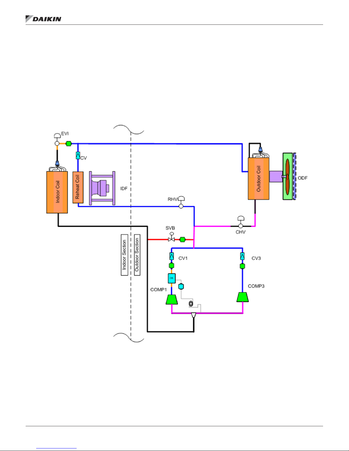
The Rebel piping system varies signicantly between the
multiple possible congurations; heat pump, cooling only, and
modulating hot gas reheat. In spite of this multiplicity there
are some consistent characteristics. All units have a single
circuit with a single or tandem compressor. All units use
an electronic expansion valve (EVI) and a start-up by pass
solenoid valve (SVB).
Figure 12: Typical Refrigeration Circuit for Cooling Only Unit with
Modulating Hot Gas Reheat (DPS 007–015 shown)
refrIgeraTIon sysTeM
refrIgeraTIon sysTeM
www.DaikinApplied.com 19 IM 1125-7 • REBEL ROOFTOPS

refrIgeraTIon sysTeM
Figure 13: Typical Refrigeration Circuit for Heat Pump Unit with Modulating Hot Gas Reheat (DPS 007–015 shown)
Item Description
EVI
EVO
CV Check Valve, size 3-15 only
REC Refrigerant Receiver
IDF Indoor fan
ODF Outdoor fan
COMP1 Inverter compressor
COMP3
SVB Bypass solenoid valve
RHV Reheat step valve
SVR Receiver solenoid valve
CHV Condenser step valve
OVI
4WV 4-way heat pump valve
OS Oil separator, size 3-15 only
Indoor coil electronic
expansion valve
Outdoor coil electronic
expansion valve
Fixed speed compressor
(7½ thru 15 ton and 25-28
only)
Outdoor electronic
expansion valve
IM 1125-7 • REBEL ROOFTOPS 20 www.DaikinApplied.com

DPS 003–015 Component Description
refrIgeraTIon sysTeM
Variable Speed Compressor
A variable speed compressor (COMP1) is used on all DPS(H)
003–015. On small cabinet units (3–6 Tons) the variable speed
compressor will be the only one present. On medium cabinet
units (7–15 Tons) the variable speed compressor will be on the
left. The discharge of the variable speed compressor is located
on the side and the suction is located on the top.
These pipes can also be identied by recalling that suction
lines will always be larger than discharge lines. The side
discharge design is used to create a positively pressurized
crank case that returns oil to the scroll set even during low turn
down conditions.
Figure 14: Compressor Suction and Discharge on Medium
Cabinet (7.5T) Heat Pump (DPH)
Compressor Suction Line
Compressor Discharge Line
Receiver
Only Rebel Heat Pump units will have a receiver. Different
volumes of refrigerant are required inside the system during
Mechanical Cooling (or defrost) and Mechanical Heating.
This is the results of the charge in operating temperatures in
Cooling and Heating Mode. The receiver stores the excess
refrigerant upstream, in Cooling Mode, of the Indoor Expansion
Valve (EVI). Three refrigerant lines connect to the receiver.
In cooling mode the refrigerant leaves (Cooling Mode) the
receiver from the bottom connection on its way to the Indoor
Expansion Valve (EVI). The refrigerant enters the receiver
by the middle connection from the Outdoor Expansion Valve
(EVO). The top connection is linked to the Receiver Solenoid
Valve (SVR) and is used to bleed refrigerant vapor out of the
top of the vessel during the change over from Mechanical
Heating to Cooling Mode (or defrost).
In heating mode the refrigerant ow path will be reversed and
will enter the receiver at the bottom connection on its way from
EVI. The refrigerant will leave the receiver from the middle
connection towards EVO. The top connection will always
be a vapor bleed connected to SVR regardless of the units
operating mode.
Figure 16: Receiver on Medium Cabinet (7.5T) Heat Pump
(DPH)
Fixed Speed Compressor (7–15 Only)
The xed speed compressor (COMP3) is used on all medium
cabinet (7–15 Ton), DPS, units. This compressor will always be
located on the right and like the variable speed has the suction
line on the top of the dome entering the scrolls and a discharge
exiting from the side of the shell.
Figure 15: Compressor Tandem on Medium Cabinet
Variable Speed
Compressor
(COMP 1)
Fixed Speed
Compressor
(COMP 3)
“Vapor Bleed”
leading to SVR
Entering Receiver
from Outdoor Coil
(Cooling Mode)
Leaving Receiver
to EVI
(Cooling Mode)
www.DaikinApplied.com 21 IM 1125-7 • REBEL ROOFTOPS

refrIgeraTIon sysTeM
Oil Separator
All DPS(H) 003–015 units will have an oil separator on the
discharge line of the compressor. This device will remove
oil from the compressor discharge gas and return it to the
compressor suction line. The oil separator has three lines
entering it. The connection on the side of the compressor
is where the discharge gas enters. The hot gas continues
on to the Outdoor Coil from the connection on the top of the
separator. On the bottom is a small drain through which the
oil returns after separation to the compressor suction. The
refrigerant and oil path through the separator will not change
depending on Heating or Cooling Mode.
Figure 17: Oil Separator
Hot Gas
Entering
Outdoor Coil
Check Valve
All DPS 003–015 will have check valves on each of the
compressor discharge lines. On medium cabinet units
(7–15 Tons), two valves, one on each compressor, prevent
recirculation of refrigerant during part load conditions. On
small cabinet units (3–6 Tons) a single check valve prevents
migration of refrigerant into the scrolls during off cycles.
Figure 19: Discharge Line Check Valves on Large Cabinet
(7.5T) Heat Pump (DPH)
Y-Joint connecting
COMP1 and COMP2
Discharge
CAUTION!
Correct Orientation
Must Be Observed
Discharge Gas
from Compressor
Oil Drain into
Compressor
Suction Line
Figure 18: Secondary Oil Separator
Secondary
Oil Separator
Direction of
Compressor
Discharge Gas
IM 1125-7 • REBEL ROOFTOPS 22 www.DaikinApplied.com

refrIgeraTIon sysTeM
High Pressure Switch
All Rebel Units will have a high pressure switch on each
compressor. Medium cabinet units (7–15 Tons) will have an
HP1 switch on the variable speed compressor (COMP1) and a
HP3 on the xed speed compressor (COMP3). These switches
are normally closed devices that are brazed directly to the
refrigerant piping. When the pressure at the switch exceeds
580 PSIG the switch will open. This opening will interrupt the
control signal to the variable compressor drive or de-energize
the contactor coil on the xed speed compressor, both acts
will shut down the compressors and generate an alarm at the
MicroTech III keypad.
Figure 20: High Pressure Switch
High Pressure Switch
(HP1)
Four-Way Valve
The Four-Way Valve (4WV) also known as a Reversing Valve
is a component only used on Heat Pumps. This device is
used to direct the discharge gas from the compressor into the
outdoor coil (Heating Mode) or indoor coil (Cooing Mode). This
device is defaulted to cooling and when un-energized will direct
the discharge gas into the outdoor coil.
Figure 22: Four-Way Valve
Compressor Discharge Gas
Cooling Mode:
Suction Vapor from
Indoor Coil
Suction Vapor
to Compressor
Heating Mode:
Discharge Gas to
Indoor Coil
Refrigerant Screen
During manufacturing, service, and repair there is always the
potential for debris to accidentally enter the sealed refrigeration
system. Filter screens are positioned around the refrigerant
circuit to prevent any possible debris from entering critical
components; expansion valves, compressors, etc. These
screens are not bi-direction and must be installed in a specic
direction if replaced. Please be aware that these screens are
not desiccant lters and provide no moisture protection for
compromised systems.
Figure 21: Refrigerant Screen
Refrigerant Screen
Cooling Mode:
Discharge Gas to
Outdoor Coil
Heating Mode:
Suction Vapor from
Outdoor Coil
www.DaikinApplied.com 23 IM 1125-7 • REBEL ROOFTOPS

refrIgeraTIon sysTeM
By-Pass Solenoid Valve
The By-Pass Solenoid Valve (SVB) is used to “short-circuit”
the high pressure compressor discharge to the low pressure
suction side during start-up. This increases compressor
longevity by minimizing starting torque and inrush current.
Figure 23: By-pass Solenoid Valve
Short Circuit between
High Pressure Discharge
and Low Pressure Suction
By-Pass
Solenoid
Valve
Indoor Expansion Valve
The Indoor Expansion Valve (EVI) is a 12 VDC stepper motor
driven valve, used in heating and cooling mode. In cooling
mode EVI is used to expand the refrigerant entering the Indoor
Coil, operating as an evaporator, in much the same way as a
TXV on a conventional air conditioner. In heating mode the EVI
can operate in two different modes, congurable at the keypad.
When congured for Standard during heating mode the EVI
will modulate to fully open and remain in this position. When
congured for heating mode the EVI will modulate to maintain
the Subcooling Set-Point.
Figure 25: Indoor Expansion Valve
Indoor
Refrigerant
Temperature
Sensor (IRT)
Indoor
Expansion
Valve (EVI)
Receiver Solenoid Valve
The Receiver Solenoid Valve (SVR) is used to “bleed off”
refrigerant vapor from the top of the Receiver during pump
down or the transition between mechanical heating and
defrost. Cooling only units will not have this component, only
Heat Pumps .
Figure 24: Receiver Solenoid Valve
Receiver
Solenoid
Valve (EVI)
Vapor Bleed
from top of
Receiver to
Compressor
Suction
Outdoor Expansion Valve
The Outdoor Expansion Valve (EVO) is a 12 VDC stepper
motor driven valve, used in heating and cooling mode. Cooling
only units will not have this component, only Heat Pumps.
In heating mode the EVO is used to expand the refrigerant
entering the Outdoor Coil, which is now and evaporator,
in much the same way as a TXV on a conventional air
conditioner. In Cooling Mode the EVO can operate in two
different modes, congurable at the keypad. When congured
for Standard during Cooling Mode the EVO will modulate
to fully open and remain in this position. When congured
for Cooling Mode the EVO will modulate to maintain the
Subcooling Set-Point.
IM 1125-7 • REBEL ROOFTOPS 24 www.DaikinApplied.com

refrIgeraTIon sysTeM
Suction Pressure Transducer
The Suction Pressure Transducer (PTS) is a refrigerant
pressure sensor that screws onto a Schrader tting on the
suction line of the compressor deck. On single compressor
units (3–6T) this sensor is located on the suction line. On
tandem, two compressor units (7–15T), the PTS is located
upstream of the joint suction.
This sensor is used to ensure that the compressor does not
leave the operating envelope and is used to regulate the super
heat leaving the indoor coil and entering the compressor.
Discharge Pressure Transducer
The Discharge Pressure Transducer (PTD) is a refrigerant
pressure sensor that screws onto a Schrader tting on
the discharge line of the compressor system. On single
compressor units (3–6T) this sensor is located on the
discharge line. On tandem, two compressor units (7–15T), the
PTD is located down stream of the joint discharge.
This sensor is used to ensure that the compressor does not
leave the operating envelope and is used to regulate the
outdoor fan speed and maintain head pressure.
Discharge Refrigerant Temperature
All Rebel units will have a Discharge Refrigerant Temperature
Sensor (DRT1 / DRT3) on the discharge line of each
compressor. This sensor is attached the piping with a metal
clip and wrapped in insulation. The purpose of this device is to
increase compressor life by preventing it from running outside
of the operating envelope.
Outdoor Refrigerant Temperature
Only Rebel Heat Pumps units will have an Outdoor Refrigerant
Temperature Sensor (ORT). This sensor is used in Cooling
Mode when ClgEVOmethod is set to control subcooling. This
sensor is attached to the refrigerant piping upstream (Cooling
Mode) of the Outdoor Expansion Valve (EVO).
Figure 26: Outdoor Expansion Valve
Outdoor Expansion
Valve (EVI)
Outdoor
Refrigerant
Temperature
Sensor (ORT)
Defrost Temperature Sensor
Only Rebel Heat Pump, DPH, units will have a Defrost
Temperature Sensor (DFT). This sensor is used in Heating
Mode and Defrost Mode to determine the amount of frost
accumulated on the Outdoor Coil.
Suction Refrigerant Temperature
All Rebel units will have a Suction Refrigerant Temperature
Sensor (SRT). This sensor is located on the suction line. Unlike
DRT1 or 3 there is only one SRT for tandem compressor
units. This sensor is used to determine the suction super heat
entering the compressor and is the control input for the EVI in
cooling mode (EVO in heating mode).
Indoor Refrigerant Temperature
Only Rebel Heat Pump units will have an Indoor Refrigerant
Temperature Sensor (IRT). This sensor is used in Heating
Mode when htgEVImethod is set to control subcooling. This
sensor is attached to the refrigerant piping downstream
(Cooling Mode) of the Indoor Expansion Valve (EVI).
www.DaikinApplied.com 25 IM 1125-7 • REBEL ROOFTOPS

refrIgeraTIon sysTeM
Heating
The unit’s heating mode of operation is determined by the
control temperature and the heating setpoint temperature. The
unit enters the heating mode of operation by comparing the
control temperature to the heating setpoint.
The control temperature can be either the return temperature
or the space temperature.
The return temperature is typically used for VAV units and the
space temperature is typically used for CAV units.
The unit goes into the heating mode of operation when the
control temperature (return or space temperature) is below the
heating setpoint by more than ½ the deadband.
For example, a standard air conditioning unit with supplemental
gas, electric, or hot water heat with a heating setpoint of 68.0ºF
and a deadband of 1.0ºF would enter heating mode if the
control temperature reached 67.4ºF. When this takes place,
the heating mode of operation will begin and the 1st Stage of
heating operation will start.
Heat Pump
(DPS 003 –015 ton)
The heating mode of operations will be slightly different for heat
pump units. It is the manufacturer’s recommendation that all
Rebel heat pump units be purchased with supplemental gas,
electric, or hot water heat. When the control temperature drops
below the heating setpoint by half the deadband the unit will
energize the four way valve and initiate mechanical heating.
On heat pumps mechanical heating is the primary source of
heat and will always be the unit’s rst attempt to meet the
application’s load. After start-up the variable compressor
will ramp up to meet the DAT Setpoint. If the mechanical
heating capacity at the ambient conditions is capable of
meeting the building load the variable speed compressor will
stabilize at some value below its maximum speed. If the heat
pump’s capacity is insufcient at the ambient conditions the
supplemental (gas, electric, hot water) heat will be enabled and
gradually ramp/stage on to make up the capacity shortage.
If the combined capacity of the heat pump’s mechanical and
supplemental heating is greater than the building load the
supplemental supply will ramp/stage down. The unit will always
seek to operate with mechanical heating as much as possible.
Periodically during heating operations the unit will need to
enter defrost to remove frost build up from the outdoor coil.
During defrost mechanical heating will be unavailable and the
supplemental heat will ramp/stage up to meet the DAT set-point.
Defrost
(DPS 003 –015 ton)
Defrost is a temporary and infrequent period during normal
heating operations on Rebel heat pumps. The purpose of
defrost is to remove frost that has built up on the outdoor coil
during mechanical heating. In heating mode the outdoor coil
acts as an evaporator to “pull” heat out of the ambient air. As a
result the surface temperature of the outdoor coil is below the
ambient temperature and depending on conditions maybe below
freezing. During prolonged mechanical heating while the surface
temperature of the outdoor coil is below 32ºF frost will form.
The defrost operation is similar to mechanical cooling. In defrost
the four way valve will de-energize and the hot gas from the
compressor will be forced into the outdoor coil, rejecting heating
to the ambient, and melting any frost formed on the coil. To
speed up the melting process during a defrost cycle the OA
damper will close and the outdoor fan will de-energize. During
this period the supplemental (gas, electric, hot water) heat will
ramp/stage up to maintain the unit’s DAT Setpoint.
Rebel heat pump unit’s have demand based defrost control
and will operate in defrost only as long as necessary to remove
frost from the outdoor coil.
Charging
Rebel units have advanced charge management systems
that obsolete many common techniques for determining
over or under charged conditions. The charge management
system means that super heat and subcooling values will
oat to achieve the peak real time energy efciency possible
at current operating conditions (building load and ambient
temperature). Rebel units also use electronic expansion valves
that can not be adjusted manually. Refrigerant should never
be added or removed from the system based on the desire to
achieve an arbitrary subcooling value. It will always be Daikin's
recommendation that unit’s suspected of being over/under
charged have all of their refrigerant removed, leak tested with
nitrogen, and then re-charged based on the unit name plate.
Table 9: Refrigerant Charge
Unit Size
3C 10.5 12.9 12.0 14.4
3M 6.6 11.3
4C 11.1 13.5 12.6 15.0
4M 6.5 11.3
5 15.3 18.2 16.8 19.7
6 15.3 18.2 16.8 19.7
7.5 11.1 17.8 26.0 31.2
10 20.0 25.8 40.0 45.8
12 20.0 25.8 40.0 45.8
15 24.4 30.2 46.0 51.8
3C & 4C with n tube outdoor coils
3M & 4M with micro-channel outdoor coils
Cooling Model Heat Pump Model
Standard Unit
Standard Unit
w/ MHGRH
Standard Unit
Standard Unit
w/ MHGRH
IM 1125-7 • REBEL ROOFTOPS 26 www.DaikinApplied.com

DPS 016–028 Ton Component Description
refrIgeraTIon sysTeM
Variable Speed Compressor
A variable speed compressor (COMP1) is used on all DPS
016-028. On DPS 16–20 ton units, the variable speed
compressor will be the only one present, and be on the right.
The discharge of the variable speed compressor is located on
the top and the suction is located on the side.
These pipes can also be identied by recalling that suction
lines will always be larger than discharge lines. The side
suction design is used to cool the motor with cold refrigerant.
Figure 27: Compressor Suction and Discharge on DPS
025–028 units
Figure 28: High Pressure Switch
High Pressure Switch
Refrigerant Screen
During manufacturing, service, and repair there is always the
potential for debris to accidentally enter the sealed refrigeration
system. Filter screens are positioned around the refrigerant
circuit to prevent any possible debris from entering critical
components; expansion valves, compressors, etc. These
screens are not bi-direction and must be installed in a specic
direction if replaced. Please be aware that these screens are
not desiccant lters and provide no moisture protection for
compromised systems.
Fixed Speed Compressor (DPS 025–028 Only)
This compressor will always be located on the left and like the
variable speed has the suction line on the side of the dome
entering the scrolls and a discharge exiting from the top of the
shell.
High Pressure Switch
All Rebel Units will have a high pressure switch on each
compressor. HP1 switch is on the variable speed compressor
(COMP1) and HP3 is on the xed speed compressor
(COMP3). These switches are normally closed devices
that are brazed directly to the refrigerant piping. When the
pressure at the switch exceeds 580 PSIG the switch will open.
This opening will interrupt the control signal to the variable
compressor drive or de-energize the contactor coil on the xed
speed compressor, Both acts will shut down the compressors
and generate an alarm at the MicroTech III keypad.
Figure 29: Refrigerant Screen
Refrigerant Screen
www.DaikinApplied.com 27 IM 1125-7 • REBEL ROOFTOPS

refrIgeraTIon sysTeM
Indoor Expansion Valve
The Indoor Expansion Valve (EVI) is a 12 VDC stepper motor
driven valve. In cooling mode EVI is used to control the
superheat and expand the refrigerant entering the Indoor Coil,
operating as an evaporator, in much the same way as a TXV
on a conventional air conditioner.
Figure 30: Indoor Expansion Valve
Indoor
Expansion
Valve
Easy
Expansion
Valve
Access
Panel
Suction Pressure Transducer
The Suction Pressure Transducer (PTS) is a refrigerant
pressure sensor that screws onto a Schrader tting on the
suction line of the compressor deck. On single compressor
units (DPS 016–020) this sensor is located on the suction line.
On tandem, two compressor units (DPS 025–028), the PTS is
located upstream of the joint suction.
This sensor is used to ensure that the compressor does not
leave the operating envelope and is used to regulate the super
heat leaving the indoor coil and entering the compressor.
Discharge Pressure Transducer
The Discharge Pressure Transducer (PTD) is a refrigerant
pressure sensor that screws onto a Schrader tting on
the discharge line of the compressor system. On single
compressor units (DPS 016–020) this sensor is located on the
discharge line. On tandem, two compressor units (DPS 025–
028), the PTD is located downstream of the joint discharge.
This sensor is used to ensure that the compressor does not
leave the operating envelope and is used to regulate the
outdoor fan speed and maintain head pressure.
Discharge Refrigerant Temperature
All Rebel units will have a Discharge Refrigerant Temperature
Sensor (DRT1/DRT3) on the discharge line of each
compressor. This sensor is attached the piping with a metal
clip and wrapped in insulation. The purpose of this device is to
increase compressor life by preventing it from running outside
of the operating envelope.
Suction Refrigerant Temperature
All Rebel units will have a Suction Refrigerant Temperature
Sensor (SRT). This sensor is located on the suction line. Unlike
DRT1 or 3 there is only one SRT for tandem compressor
units. This sensor is used to determine the suction super heat
entering the compressor and is the control input for the EVI in
cooling mode.
Bypass Solenoid
The bypass solenoid (SVB) is used to “short circuit” the high
pressure compressor discharge to the low pressure suction
side during startup. This increases compressor life by reducing
the startup torque and inrush current.
IM 1125-7 • REBEL ROOFTOPS 28 www.DaikinApplied.com

VFD Compressor Operation – DPS 016–028
VFD compressor modulation is controlled by a Mobus® signal
from the unit controller. The minimum VFD compressor speed
is 25 rps (1500 rpm) and the maximum VFD compressor speed
is 100 rps (6000 rpm), but the minimum and maximum limits
per unit may vary depending on operating conditions and unit
model size.
The VFD compressor is a 4 pole motor design that operates off
a frequency signal from the VFD between 50Hz and 200Hz.
At Start-up the VFD compressor will automatically ramp up to
50 rps for rst 10 seconds for lubrication requirements.
Crankcase heating for VFD Compressor is performed by the
VFD via DC-holding current through the motor windings.
VFD compressor modulation is additionally monitored and
adjusted in order to maintain operation within the approved
compressor operating envelope.
Table 10: VFD Compressor Modulation Ranges
VFD Modulation Range
VFD Max rps
DPS Unit
Model
016 25 rps/0 Vdc 60 rps/4.0 V 90 rps/6.0 V
018 25 rps/0 Vdc 100 rps/8.7 V 100 rps/10.0 V
020 25 rps/0 Vdc 100 rps/8.7 V 100 rps/10.0 V
025 25 rps/0 Vdc 85 rps/8.0 V 100 rps/10.0 V
028 25 rps/0 Vdc 85 rps/8.0 V 100 rps/10.0 V
* High and Low Oil Boost are explained on page 30
VFD Min rps/
VFD Min V
VFD and Fixed
Comp(s) ON
1 Fixed ON
VFD1Max rps/
VFD1MaxV
VFD Comp Only
VFDMax rps/
VFDMaxV
refrIgeraTIon sysTeM
DPS Size 025 & 028, Two Compressor Units
If the VFD compressor were to become inoperative, the
unit can continue to operate on the remaining xed speed
compressor until the unit can be serviced.
When the VFD compressor is at its maximum speed and
more capacity is required, a xed speed compressor is started
while the VFD compressor is reduced to minimum speed at
which point it resumes modulating to maintain the discharge
temperature. When the VFD compressor is at its minimum
speed and less capacity is required, a xed speed compressor
is turned OFF while the VFD compressor is increased to
maximum speed at which point it resumes modulating to
maintain discharge temperature.
www.DaikinApplied.com 29 IM 1125-7 • REBEL ROOFTOPS

refrIgeraTIon sysTeM
VFD Compressor Control
Control of the VFD compressor is accomplished with a digital
output enable signal and a 0-10VDC analog modulating
control signal.
General VFD Compressor Start Sequence
On a call for VFD compressor operation the VFD enable
output is energized (on) and the 0-10VDC analog control
signal is set to 3.33VDC (50 rps) for 10 seconds. During this
10 second initial period the VFD compressor’s internal logic
ramps the compressor to 50 rps to insure compressor startup oil
lubrication. After 10 seconds the VFD compressor control signal
begins modulation to maintain the cooling discharge set point.
Compressor Stage Up Transition (DPS 025 & 028 Only)
When the VFD compressor has been operating at maximum
capacity for the cooling stage time period and there is a call
for more cooling capacity the following transition sequence is
followed when staging up.
During the xed compressor stage UP sequence, the VFD
compressor speed is reduced to its minimum, as a xed speed
compressor is turned on. Note that the VFD compressor speed
range is extended for these staging points to assure smooth
transition and to minimize capacity gaps. Typically, the VFD
compressor is overdriven (higher speed than normal full load
rating speed) before staging up the xed compressor. The
VFD is held at minimum speed for 30 seconds before normal
modulation resumes.
Compressor Stage Down Transition (DPS 025 & 028 Only)
When the VFD compressor has been operating at minimum
capacity for the cooling stage time period and there is a call
for less capacity the following transition sequence is followed
when staging down.
During the xed speed compressor stage DOWN sequence,
the VFD compressor speed is increased to maximum speed
(which varies with unit size and number of operating xed
compressors) as the xed speed compressor is turned
off. Note that the VFD compressor speed range has been
extended for these staging points to assure smooth transition
and to minimize capacity gaps. Typically, the VFD compressor
will be overdriven (higher speed than normal full load rating
speed) when staging down the xed compressor.
Dehumidication Transition During Cooling State
When dehumidication operation becomes active while the
unit is in the Cooling operating state, The VFD compressor
is ramped to its maximum capacity. If the VFD capacity at
this point is already above 75% of its full modulation a xed
compressor is also turned on. The compressors are held at this
capacity for 1 minute before normal modulation resumes, to
maintain leaving coil temperature (LCT).
• VFD compressor will load up completely before starting
any xed speed compressors to achieve LCT of 45F
(default) with the VFD compressor option. LCT may be
set between 45F to 52F.
• If reheat signal is at 100% for 10 minutes and the unit is
unable to raise the DAT to desired point, the controller
will stage off the xed compressor and modulate the VFD
compressor speed to achieve the DAT set point.
Oil Balance/Boost Operational Sequence
When a low oil level is indicated in the VFD compressor sump,
the unit switches to either an oil balance or oil boost state. The
VFD compressor speed is increased during these modes to
promote the return of refrigerant oil to the VFD compressor.
To avoid short cycling of the oil balance/boost sequence, no
action is taken until a low oil indication has been present for 5
consecutive run minutes.
The unit determines whether to enter the oil balance or oil
boost mode based on the running conditions when a low oil
indication is experienced. The balance mode is only used when
a VFD compressor is part of a tandem compressor set. The
balance mode is usually entered rst, and is utilized to move
oil from the xed speed compressor to the VFD compressor. If
this mode fails to resolve the low oil indication issue, the unit
will then go into the boost mode. The boost mode is utilized
to return oil from the refrigerant system to the compressors.
VFD compressors that are not part of a tandem compressor
arrangement will skip the balance mode and only utilize the
boost mode.
The balance mode will be entered if the VFD compressor is
part of a tandem compressor arrangement and the xed speed
compressor is running, and there is a low oil indication. Upon
entering the oil balance mode the xed speed compressor
is turned off and the VFD compressor speed is increased to
the oil boost value shown in Table 9 on page 26. The VFD
compressor runs at this condition until the optical oil sensor
veries that oil is present for 3 continuous minutes. Unit
Controller default is set for a 10 minute max balance.
IM 1125-7 • REBEL ROOFTOPS 30 www.DaikinApplied.com
 Loading...