

Daikin BRP069A71 Installation manuals
Installation manual
WLAN adapter heating
BRP069A71
Installation manual
WLAN adapter heating
English
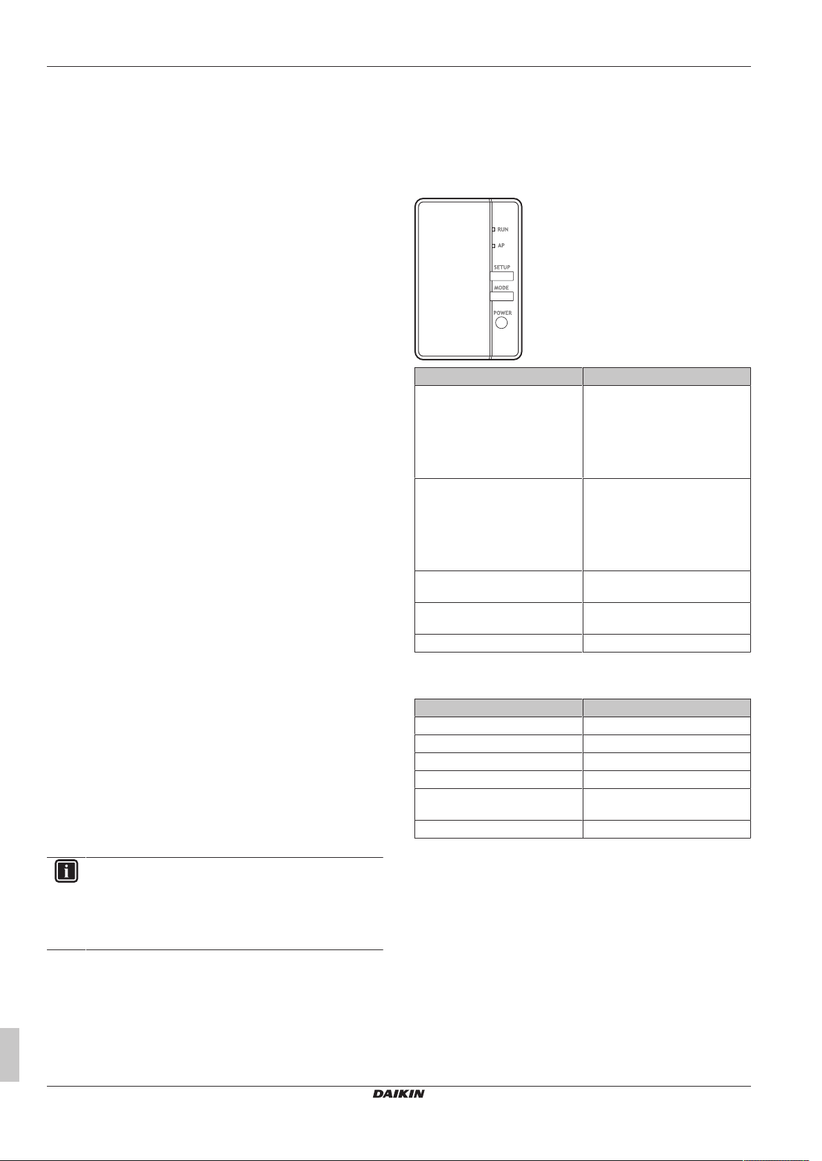
Table of contents
Table of contents
1 About this document 2
2 About the adapter 2
2.1 Components .............................................................................. 2
2.2 Basic parameters ...................................................................... 2
2.3 Compatibility.............................................................................. 2
3 About the box 2
3.1 To unpack the adapter .............................................................. 2
4 Preparation 3
4.1 Installation site requirements..................................................... 3
4.2 Overview of electrical connections ............................................ 3
5 Installation 3
5.1 Precautions when installing the adapter.................................... 3
5.2 Connecting the electrical wiring................................................. 3
5.2.1 To connect the adapter with the unit........................... 3
5.3 Closing the adapter ................................................................... 4
5.3.1 To close the adapter ................................................... 4
5.4 Mounting the adapter ................................................................ 4
5.4.1 To mount the adapter to the unit................................. 4
6 Starting up the system 4
7 Hand-over to the user 5
1 About this document
Target audience
Authorised installers
Documentation set
This document is part of a documentation set. The complete set
consists of:
▪ General safety precautions
▪ Safety instructions that you must read before installing
▪ Format: Paper (in the box of the indoor unit)
▪ Installation manual:
▪ Installation instructions
▪ Format: Paper (supplied in the kit)
▪ Installer reference guide:
▪ Installation instructions, configuration, application guidelines,…
▪ Format: Digital files on http://www.daikineurope.com/support-
and-manuals/product-information/
▪ Declaration of conformity
2 About the adapter
Wireless LAN adapter to connect the heat pump system to the
internet, allowing for control of the heat pump system with the Daikin
Residential Controller app.
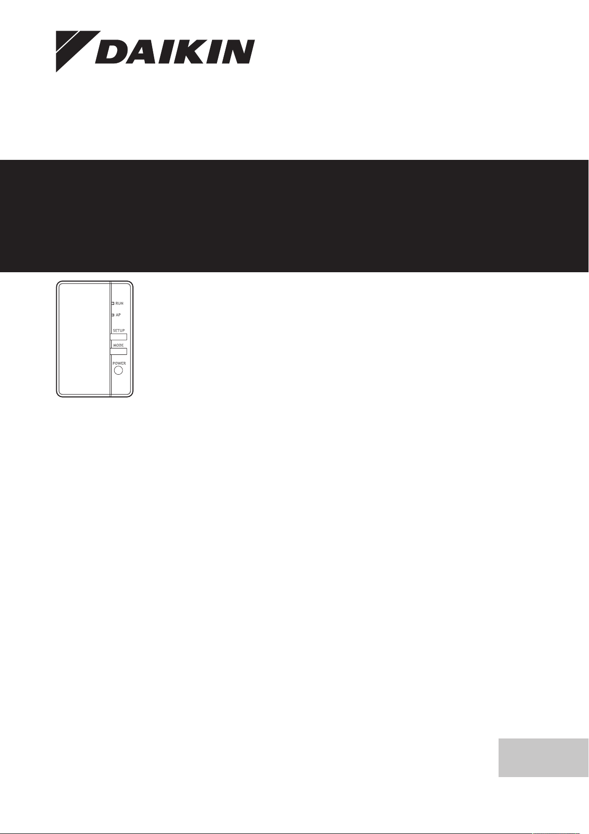
2.1 Components
Component Description
RUN ▪ LED ON: adapter active as
station, and connected to a
network.
▪ LED flashing: adapter active
as station and not yet
connected to a network.
AP ▪ LED ON: adapter active as
access point, and mobile
device associated.
▪ LED flashing: adapter active
as access point, but no mobile
device associated yet.
SETUP Press to connect the adapter to a
router.
MODE Hold to toggle AP mode on and
off.
POWER Press to reset the adapter.
2.2 Basic parameters
Parameter Value
Frequency range 2400MHz~2483.5MHz
Radio protocol IEEE 802.11b/g/n
Radio frequency channel 1~13
Output power 0dBm~18dBm
Effective radiated power 17dBm (11b) / 14dBm (11g) /
13dBm (11n)
Power supply DC 14 V / 100 mA
INFORMATION: Declaration of conformity
Hereby, Daikin Europe N.V. declares that the radio
equipment type BRP069A71 is in compliance with the
Directive 2014/53/EU. The original declaration of
conformity is available from http://www.daikineurope.com/
support-and-manuals/product-information/.
Latest revisions of the supplied documentation may be available on
the regional Daikin website or via your dealer.
The original documentation is written in English. All other languages
are translations.
Installation manual
2
2.3 Compatibility
Make sure the heat pump system is compatible for use with the
adapter. For more information, see the installer reference guide of
the heat pump system.
3 About the box
3.1 To unpack the adapter
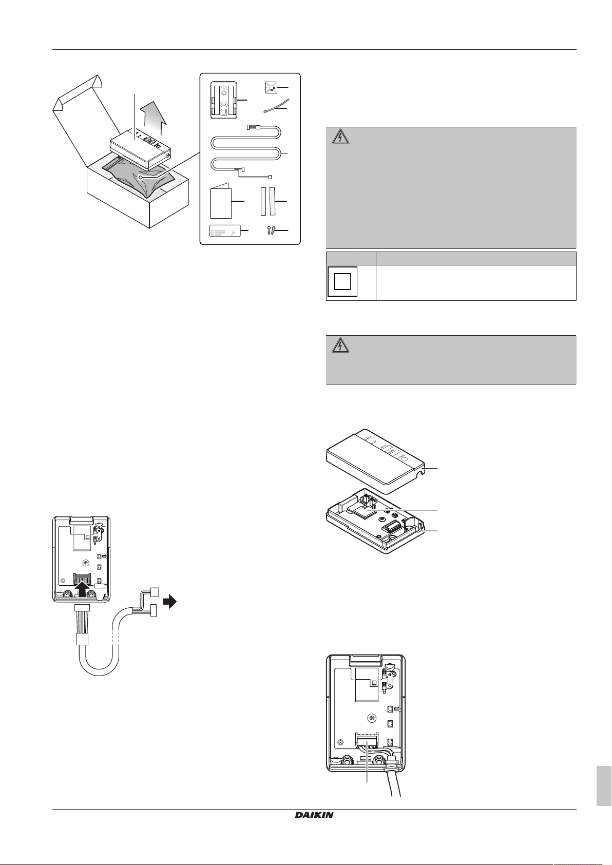
1 Open the box.
2 Take out the adapter.
BRP069A71
WLAN adapter heating
4P595892-1A – 2019.12
4 Preparation
a
b
i
c
e
gf
h
d
a
a
c
b
a
3 Separate the accessories.
a Adapter
b Adapter holder with double-sided tape
c Cable tie mounting
d Cable tie
e Connection cable
f Installation manual
g Tape for adapter holder
h Label for manual
i Screws
4 Preparation
4.1 Installation site requirements
▪ The adapter is designed to be mounted to the indoor unit, in dry,
indoor locations only.
▪ The exact location of the adapter depends on the type of indoor
unit. For more information, see the addendum book for optional
equipment of the indoor unit.
▪ The adapter is designed to operate in ambient temperatures
ranging from 5~35°C.
5 Installation
5.1 Precautions when installing the adapter
DANGER: RISK OF ELECTROCUTION
▪ Turn off the power supply before installing the adapter.
▪ Do NOT handle the adapter with wet hands.
▪ Do NOT let the adapter get wet.
▪ Do NOT disassemble, modify or repair the adapter.
▪ Grip the connector when disconnecting the connection
cable.
▪ Turn off the power supply in case the adapter gets
damaged.
Symbol Explanation
The protection of appliances marked with this symbol
is ensured by double insulation and does not require a
safety connection to electrical earth (ground).
5.2 Connecting the electrical wiring
DANGER: RISK OF ELECTROCUTION
Do NOT turn on the power supply before you have
connected the electrical wiring, closed the adapter, and
mounted it to the indoor unit.
5.2.1 To connect the adapter with the unit
1 Separate the upper casing from the lower casing.
4.2 Overview of electrical connections
a To indoor unit
a Upper casing
b Adapter PCB
c Lower casing
2 Connect the forked end of the connection cable to the indoor
unit.
3 Connect the other end of the connection cable to the connector
on the adapter PCB.
4 Fasten the cable and ensure strain relief.
BRP069A71
WLAN adapter heating
4P595892-1A – 2019.12
Installation manual
3
 Loading...