


VTS User’s Manu al
V 1.0.1

Important Safeguards and Warnings
Please read the following safeguards and warnings carefully before using the product in
order to avoid damages a nd los ses .
Note:
Do not expose the device to la mpb lack, steam or dust. Otherwise it may cause fire
or electric shock.
Do not install the device at position exposed to sunlight or in high temperature.
Temperat ur e r ise in device may cause fire.
Do not expose the device to hum id e nvironment. Otherwise it may cause fire.
The device must be installed on solid and flat surface in order to gu ar antee safety
under load and earthquake. Otherwise, it may cause device to fall off or turnover.
Do not place the device on carpet or quilt.
Do not block air vent of the dev ice or ventilation around the devic e. Otherwise,
temperature in device wil l rise an d m ay cause fire.
Do not place any object on the dev ice.
Do not disassemble the d evice without professional inst ruc t i on.
Warning:
Please use battery proper ly to avoid fire, explosion and other dangers.
Please replace used batte r y with battery of the same type.
Do not use power line other than the one specified. Please use it pr operly.
Otherwise, it may cause fir e or elect r i c shock.
Privacy Protection Notice
As the device user or data controller, you might collect personal data of others' such as
face, fingerprints, car plate number, Email address, phone number, GPS and so on. You
need to be in compli ance wi th t he loc al pri v acy prot ecti on law s and r egulat ions t o protect
the legitimate rights and interests of other people by implementing measures include but
not limited to: providing clear and visible identification to inform data subject the
existence of surveillance area and providing related contact.
About the Manual
The Manual is for reference only. If there is inconsistency between the
Manual and the actual product , the actual product shall prevail.
We are not liable for any loss caused by the operations that do not comply
with the Manual.
The Manual would be updated according to the latest laws and regulations
ii

of related regions. For detailed information, see the paper User's Manual,
CD-ROM, QR code or our official website. If there is inconsistency between
paper User's Manual and the electronic version, the electronic version shall
prevail.
All the designs and softwar e are subject to change without prior written notice.
The product updates might cause some differences between the actual
product and the Manual. Please contact the customer service for the latest
program and supplementa r y documentation.
There still might be deviation in technical data, functions and operations
description, or errors in print. If there is any doubt or dispute, please refer to
our final explanation.
Upgrade the reader software or try other mainstream reader software if the
Guide (in PDF format) can not be opened.
All trademarks, registered tr ademarks and the company names in the Manual
are the properties of their res pective owners.
Please visit our website, contact the supplier or customer service if there is
any problem occurred when using the device.
If there is any uncert ainty or controvers y , pleas e refer to our final explanation.
iii

Table of Contents
错误!未定义书签。
Important Safeguards and Warnings ................................................................................... ii
Special Announcement ............................................................
1. Product Overview ......................................................................................................... 1
1.1. Product Intro ...................................................................................................... 1
1.1.1. Product Description ................................................................................ 1
1.1.2. Features .................................................................................................. 1
1.2. Device Structure ................................................................................................ 1
1.2.1. Front Panel ............................................................................................. 1
1.2.2. Rear Panel .............................................................................................. 3
2. Wiring ............................................................................................................................ 5
2.1. Device Wiring..................................................................................................... 5
2.2. Device Networking ............................................................................................. 5
3. Project Setup ................................................................................................................ 6
3.1. Login Interface ................................................................................................... 6
3.2. Device Info ......................................................................................................... 6
3.3. Add VTH/Fence Station ..................................................................................... 7
3.4. SIP Server ......................................................................................................... 9
3.5. Add IPC ........................................................................................................... 10
3.6. Call Test ........................................................................................................... 11
3.7. Default ............................................................................................................. 12
4. Daily Operation ........................................................................................................... 13
4.1. Monitor ............................................................................................................. 13
4.2. Call ................................................................................................................... 15
4.2.1. Shout ..................................................................................................... 15
4.2.2. Call Resident ........................................................................................ 16
4.2.3. Call Record ........................................................................................... 17
4.3. Message .......................................................................................................... 19
4.4. Unlock .............................................................................................................. 20
4.5. Version ............................................................................................................. 21
4.6. Basic Config ..................................................................................................... 21
4.6.1. Display .................................................................................................. 21
4.6.2. Ring ....................................................................................................... 21
4.6.3. T alk Time ............................................................................................... 22
4.6.4. SD Card ................................................................................................ 23
4.6.5. Default ................................................................................................... 23
Appendix 1 ......................................................................................................................... 24
iv

1. Product Overview
1.1. Product Intro
1.1.1. Product Description
VTS as the contact center and ser vice center of a system, can:
Bidirectional video walk among guest, VTH, VTO and fence station.
Monitor IPC, VTO and fence station.
Remote lock.
VTH, VTO can one-click call VTS.
1.1.2. Features
Easy operation, no installation requir ed, br acket 0~45° adjustable.
Max manage 50 VTS.
Simultaneously multi-channel monitor, max support 4-ch 720 P.
Capacitance touch screen 10 inch LCD, human-computer interaction.
Hands-free call and handset.
SD card expansion
2-ch USB port
1-ch HDMI output, max resolution 1024*600.
1.2. Device Structure
Device supports desktop position, and you can adjust its position and angle (0~45°) via
adjustment level at rear.
1.2.1. Front Panel
See Figure 1-1.
1
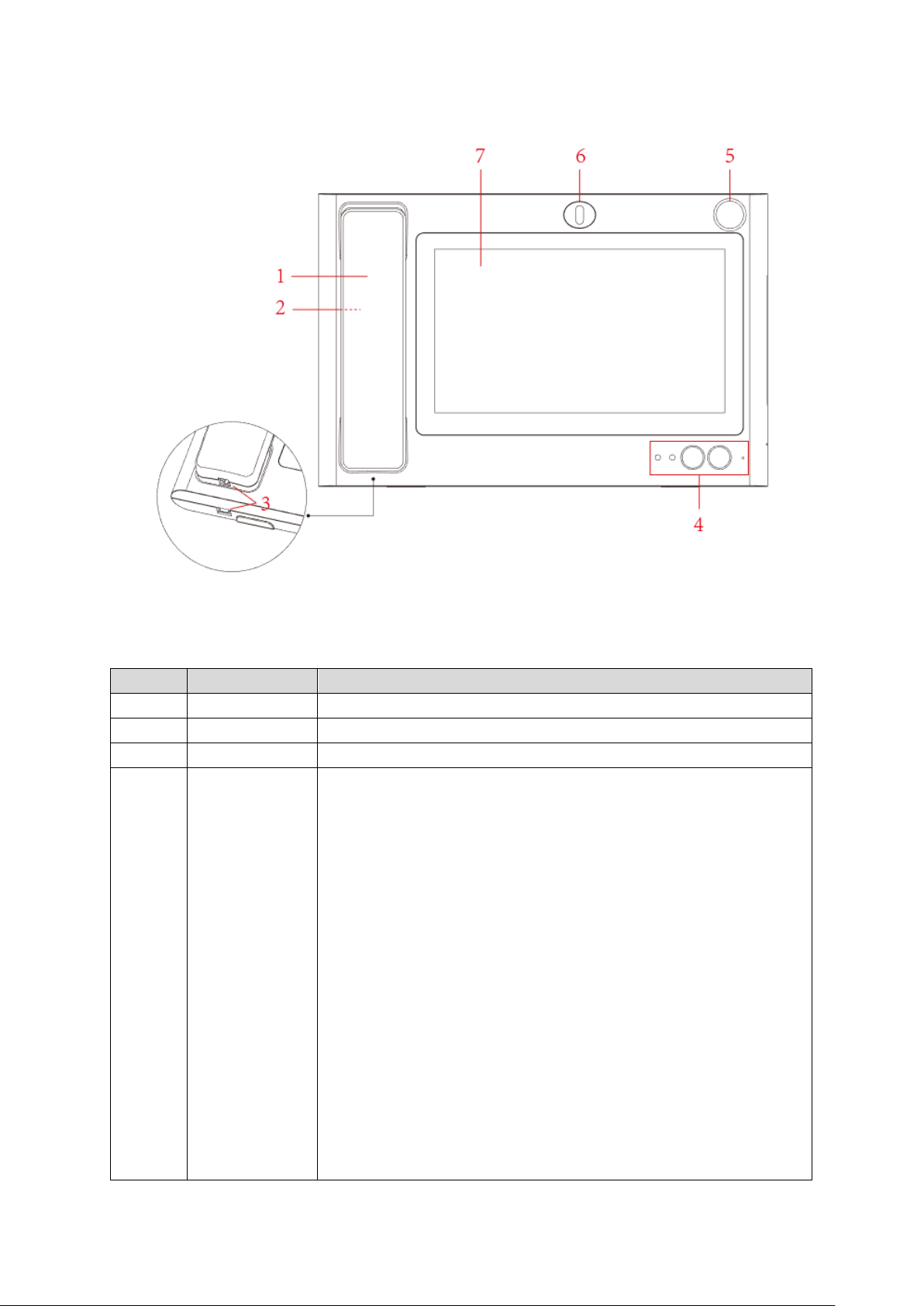
Figure 1-1
No.
Parameter
Note
If the indicator light is on, it indicates that the device has a
of being called, monitoring status, call status
Built-in MIC
Please refer to the following sheet for detailed information.
1 MIC Lifts MIC, audio and pickup ar e both on MIC.
2 Speaker Sound output.
3 Telephone Port Connect VTS and MI C.
4
From left to right:
Power indicator
If the indicator is on, it ind i cates that the d ev ice is po wer ed on.
If the indicator is off, it indicates that the device is not
connected to the power supp ly.
Information indicator
missed call. The ind icator light is of f, indicat ing that t he missed
Indicator
call has been processed or there is no missed call.
Unlock button
In the status
management machine, press the device on the unlock button,
you can remotely open the door machine door lock.
Hands-free button
Used to answer incoming calls, switch handsfree or Handset
mode.
2
No. Parameter Note
7
Display and
Screen and touch area.
No.
Parameter
Note
1
Camera
Adjust camera angle up a nd dow n.
Port
Alarm input port 1.
Sound input.
5 MIC
6 Camera
(optional)can connect t o ext er nal gooseneck MIC
(optional)adjust up and down for camera angle
Touch
1.2.2. Rear Panel
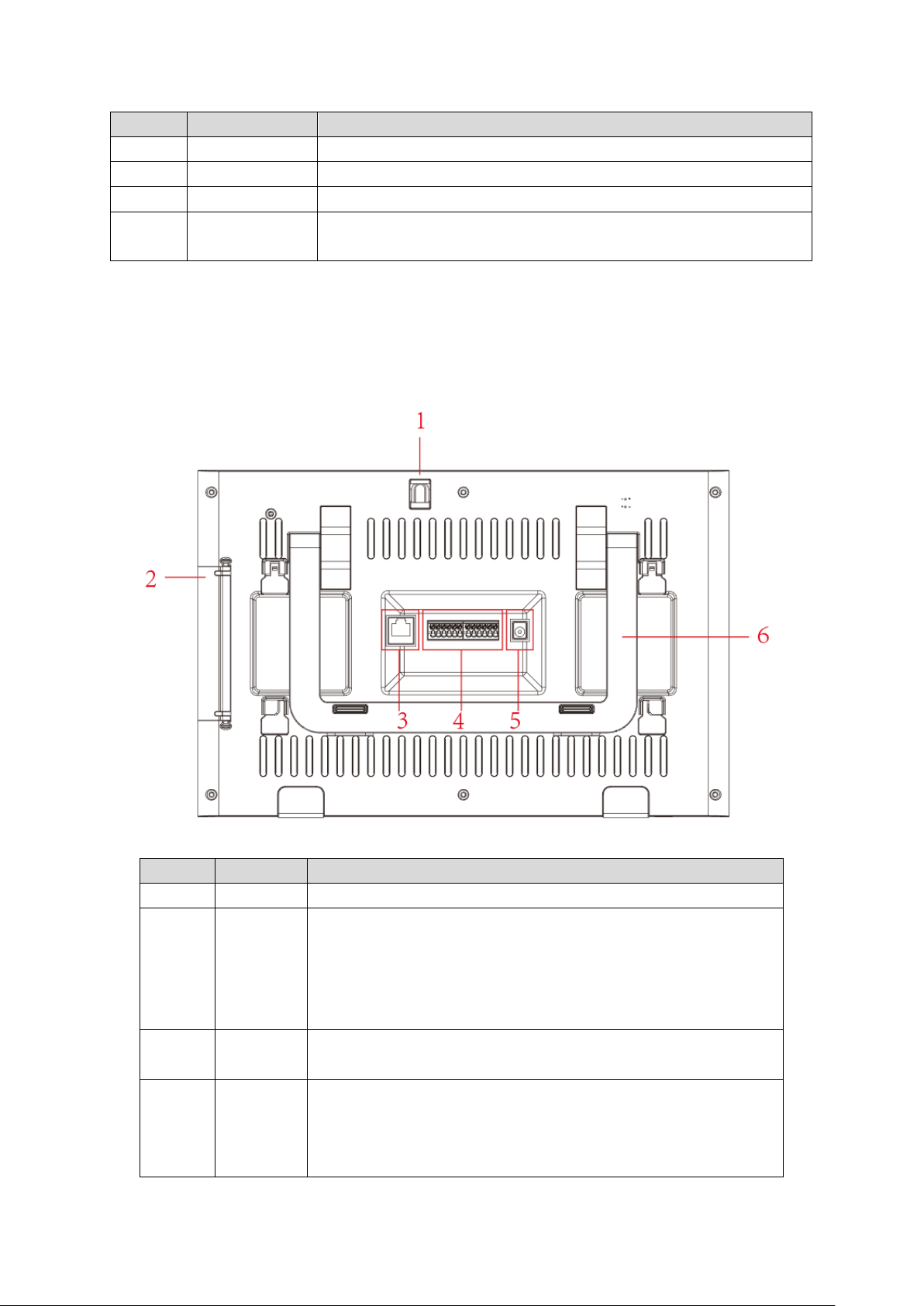
See Figure 1-2.
2 Port
3 Network
4
12-pin
Port
Figure 1-2
Open rear cover, ports from up to down:
HDMI video transmission port, for video only.
USB port.
USB port.
SD card slot.
Plug in RJ45 Ethernet cable.
Ports from left to right are :
Power output port
GNS
3

No. Parameter Note
Port
Place VTS on desktop, adjust level to adjust VTH to an
Alarm input port 2.
Alarm input port 3.
Alarm input port 4.
Power input port.
GND.
RS485A port.
RS485B por.
Alarm output port NO.
Alarm output port COM.
5 Power
DC 12V power
6
Bracket
appropriate position.
4
2. Wiring
2.1. Device Wiring
Please use our standard power supply, not self-powered.
Before wiring, please understand the structure of the device. For details, refer to Ch
1.2.
Before turning on the power , make sure all wiring is correct. Power runnin g, the normal
working state for the power indicator light is always red.
2.2. Device Networking
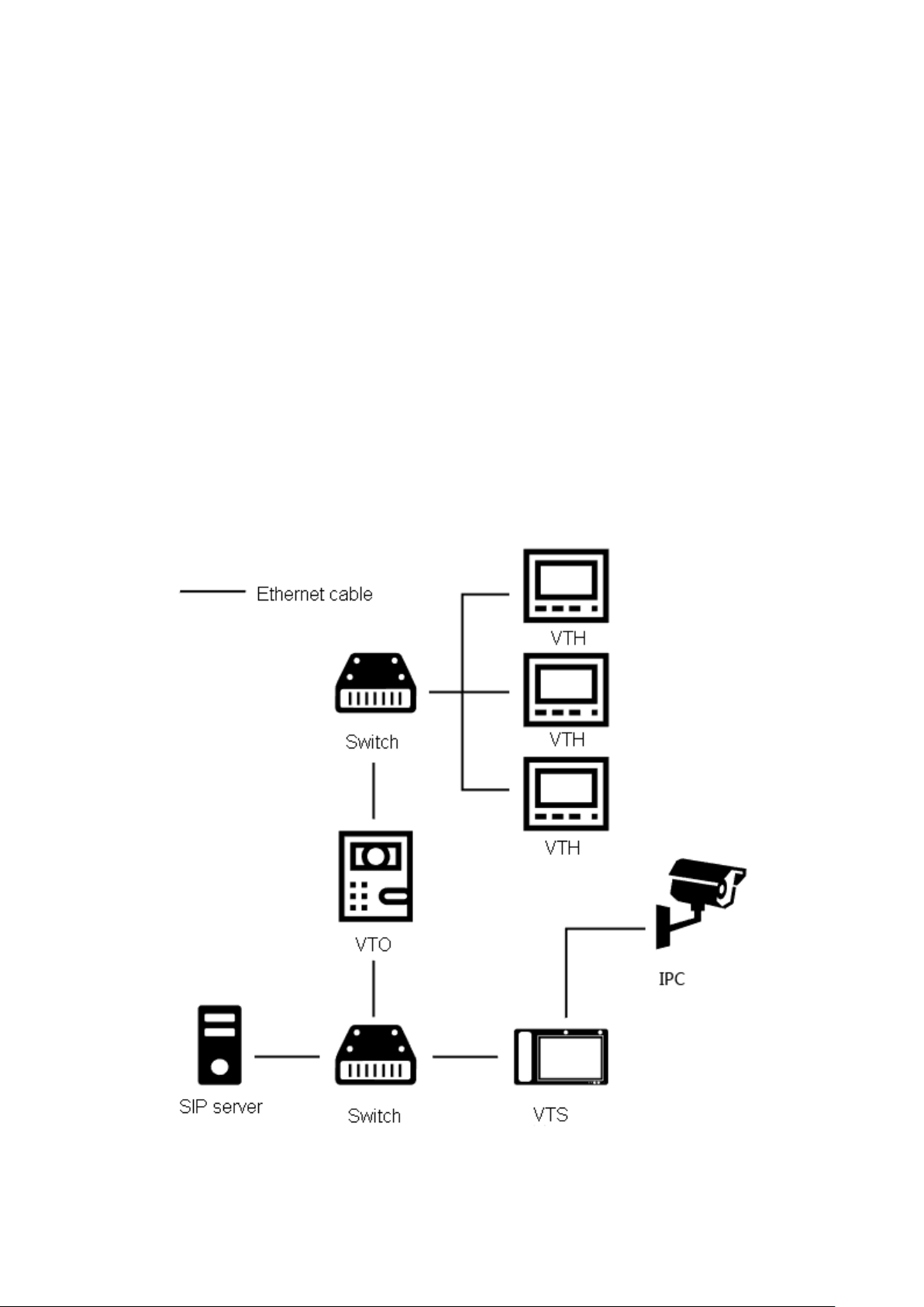
See Figure 2-1.
Figure 2-1
5
 Loading...