


Digital Villa VTO (VTO2 series) User’s Manual
V1.0.1

Table of Contents
1 Product Overview ........................................................................................ 1
1.1 Intro to Product ............................................................................................... 1
1.2 Applicable Models ........................................................................................... 1
2 Structure ...................................................................................................... 2
2.1 Front Panel ..................................................................................................... 2
2.2 Rear Panel ...................................................................................................... 3
3 Networking Scene ........................................................................................ 4
4 Installation and Debug ................................................................................. 5
4.1 Device Wiring .................................................................................................. 5
4.2 Device Installation ........................................................................................... 5
4.2.1 Screw .................................................................................................... 6
4.2.2 Installation Step .................................................................................... 6
4.3 Debug Device ................................................................................................. 7
4.3.1 Before Debugging ................................................................................. 7
4.3.2 Debug Device ....................................................................................... 8
4.3.3 Successfully Debug............................................................................. 11
5 Web Config .................................................................................................. 1
5.1 WEB Login and Logout ................................................................................... 1
5.1.1 Login ..................................................................................................... 1
5.1.2 Logout ................................................................................................... 1
5.2 System Config ................................................................................................. 2
5.2.1 Local Config .......................................................................................... 2
5.2.2 LAN Config ........................................................................................... 7
5.2.3 Indoor Manager ..................................................................................... 8
5.2.4 Network Config ................................................................................... 10
5.2.5 Video Set ............................................................................................ 12
5.2.6 User Manager ..................................................................................... 14

5.2.7 IPC ...................................................................................................... 16
5.2.8 WIFI Info ............................................................................................. 17
5.3 Info Se arch.................................................................................................... 17
5.3.1 Call History ......................................................................................... 18
5.3.2 Alarm Record ...................................................................................... 18
5.3.3 Unlock Rec ord .................................................................................... 18
5.4 Status Statistics ............................................................................................ 19
6 Basic Function Introduction ........................................................................ 20
6.1 Monitor .......................................................................................................... 20
6.2 Call Function ................................................................................................. 20
6.3 Unlock ........................................................................................................... 20
6.4 Restore Backup ............................................................................................ 20
Appendix 1 Technical Specifications ....................................................................... 21

Important Safeguards and Warnings
Please read the following safeguards and warnings carefully before using the product in
order to avoid damages and losses.
Note:
Do not expose the device to lampblack, steam or dust. Otherwise it may cause
fire or electric shock.
Do not install the device at position exposed to sunlight or in high temperature.
Temperature rise in device may cause fire.
Do not expose the device to humid environment. Otherwise it may cause fire.
The device must be installed on solid and flat surface in order to guarantee
safety under load and earthquake. Otherwise, it may cause device to fall off or
turnover.
Do not place the device on carpet or quilt.
Do not block air vent of the device or ventilation around the device. Otherwise,
temperature in device will rise an d m ay cause fire.
Do not place any object on the device.
Do not disassemble the device without pr ofessional instruction.
Warning:
Please use battery properly t o avoid fir e, explosion and other dangers.
Please replace used battery w ith bat t ery of the same type.
Do not use power line other than the one specified. Please use it properly.
Otherwise, it may cause fire or elect r i c s hock.
Privacy Protection Notice
As the device user or data controller, you might collect personal data of others' such as
face, fingerprints, car plate number, Email address, phone number, GPS and so on. You
need to be in compliance with the local privacy protection laws and regulations to
protect the legitimate rights and interests of other people by implementing measures
include but not limited to: providing clear and visible identification to inform data
subject the existence of surveillance area and providing related contact.
About the Manual
The Manual is for reference only. If there is inconsistency between the
Manual and the actual product , t he ac t ual product shall prevail.
We are not liable for any loss caused by the operations that do not comply
with the Manual.
The Manual would be updated according to the latest laws and regulations

of related regions. For detailed information, see the paper User's Manu al,
CD-ROM, QR code or our official website. If there is inconsistency between
paper User's Manual and the electronic version, the electronic version shall
prevail.
All the designs and software are subject to change without prior written
notice. The product updates might cause some differences between the
actual product and the Manual. Please contact the customer service for the
latest program and suppleme ntary documentation.
There still might be deviation in technical data, functions and operations
description, or errors in print. If there is any doubt or dispute, please refer to
our final explanation.
Upgrade the reader software or try other mainstream reader software if the
Guide (in PDF format) cannot be opened.
All trademarks, registered trademarks and the company names in the
Manual are the properties of their respective owners.
Please visit our website, contact the supplier or customer service if there is
any problem occurred wh en using the device.
If there is any uncertainty or controversy, please refer to our final
explanation.

1
1 Product Overview
1.1 Intro to Product
Digital villa VTO h as easy operation, simple installati on and support:
WIFI
Mobile phone live preview
Call VTH, and perform video talk
Door unlock by card
One-click MGT center
Vandal-proof alarm and etc.
1.2 Applicable Models
Model Color
Unlock via
IC card
Button Ty pe
Lock Control
Module
POE WIFI
VTO2111D-WP Black Support
Mechanical
keypad
Support built-in
and external
Support Support
VTO2111D-W Black Support
Mechanical
keypad
Support built-in
and external
Not
support
Support
VTO2111D Black Support
Mechanical
keypad
Support built-in
and external
Not
support
Not
support
2
2 Structure
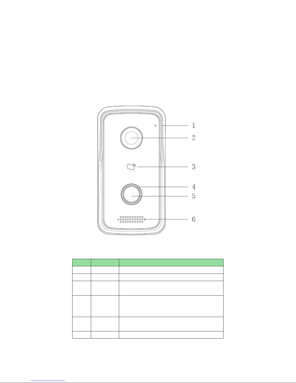
2.1 Front Panel
Device front panel is in Figure 2-1. Description of each component is in Chart 2-1.
Figure 2-1
No. Port Name Note
1 MIC Audio input.
2 Camera It monitors corresponding door region.
3 Card Area
Authorize IC card to unlock (card issuing),
swipe card to unlock.
4 Indicator In standby s tatus, blue light is NO.
Network offline, blu
e light flashes when
call VTH or MGT center.
5 Call
Button
Call MGT center or VTH.
6 Speaker Audio output.
Chart 2-1
3
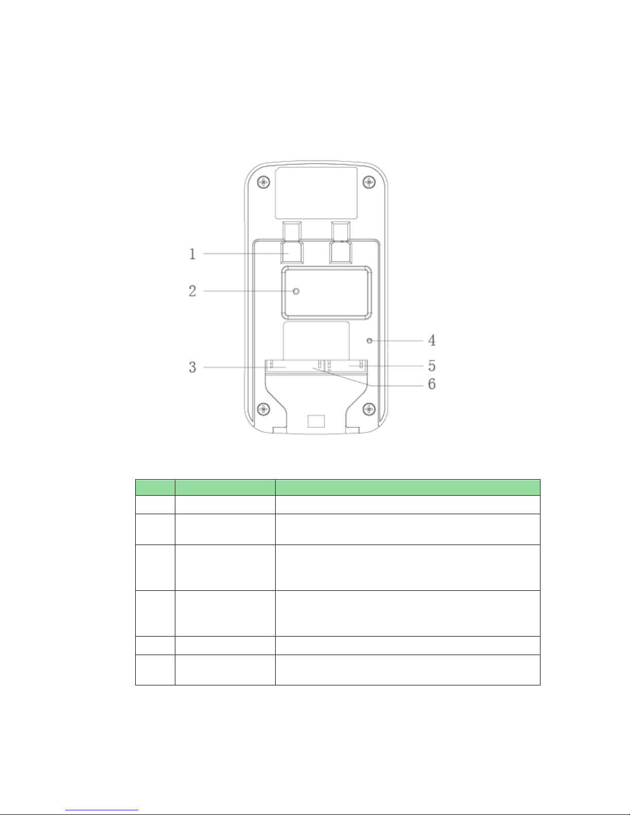
2.2 Rear Panel
Device rear panel is in Figure 2-2. Description of each component is in Chart 2-2.
Figure 2-2
Chart 2-2
No.
Component Name
Note
1 Bracket Position Bracket used to fix device and w all.
2
Vandal-proof
Switch
When villa VTO is forced to leave wall, it will alarm and
send alarm to MGT center.
3
Alarm
Input/output
Interface
1-ch alarm input.
4 RESET Key
Shortly press this key to config reset WIFI.
Long press this key for 10s
, system will restore
default settings.
5 RJ45 Interface Standard Ether net c able, support POE power.
6
Power Input
Interface
DC 12V input, support 9V-26V
wide voltage, with
anti-reverse connection.
4
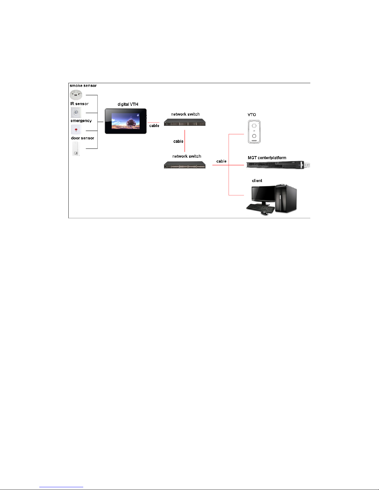
3 Networking Scene
Villa VTO networking scene is in Figure 3-1.
Figure 3-1
5
4 Installation and Debug
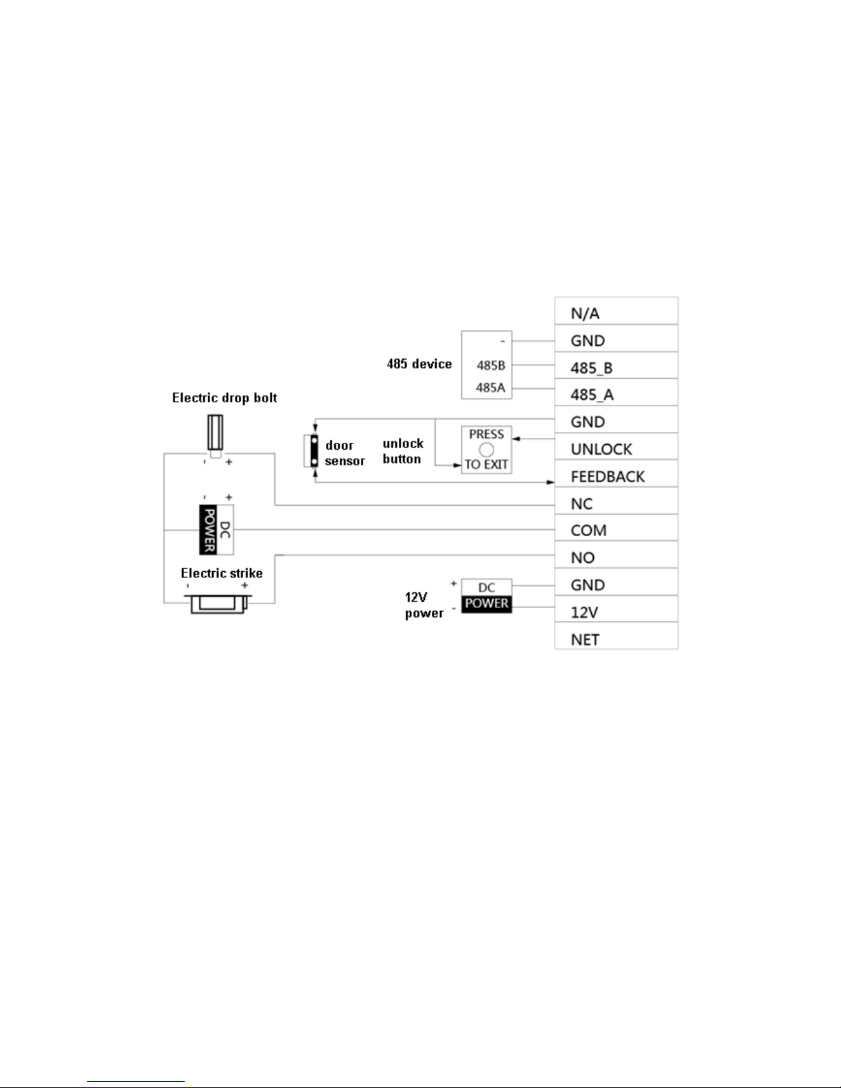
4.1 Device Wiring
Device wiring is in Figure 4-1.
Figure 4-1
4.2 Device Installation
Warning:
Avoid installation in poor environment, such as condensation, high temperature, oil
stain, dust, corrosion or di r ect s unl ight.
Project installation and debugging must be done by professionals. Please do not
open the device in case of failure, and please contact after sales service.
6
4.2.1 Screw
For installation, pleas e use screw according to Chart 4-1.
Component Name
Illustration
Quantity
M4×30 cross pan head
machine screw
2
Chart 4-1
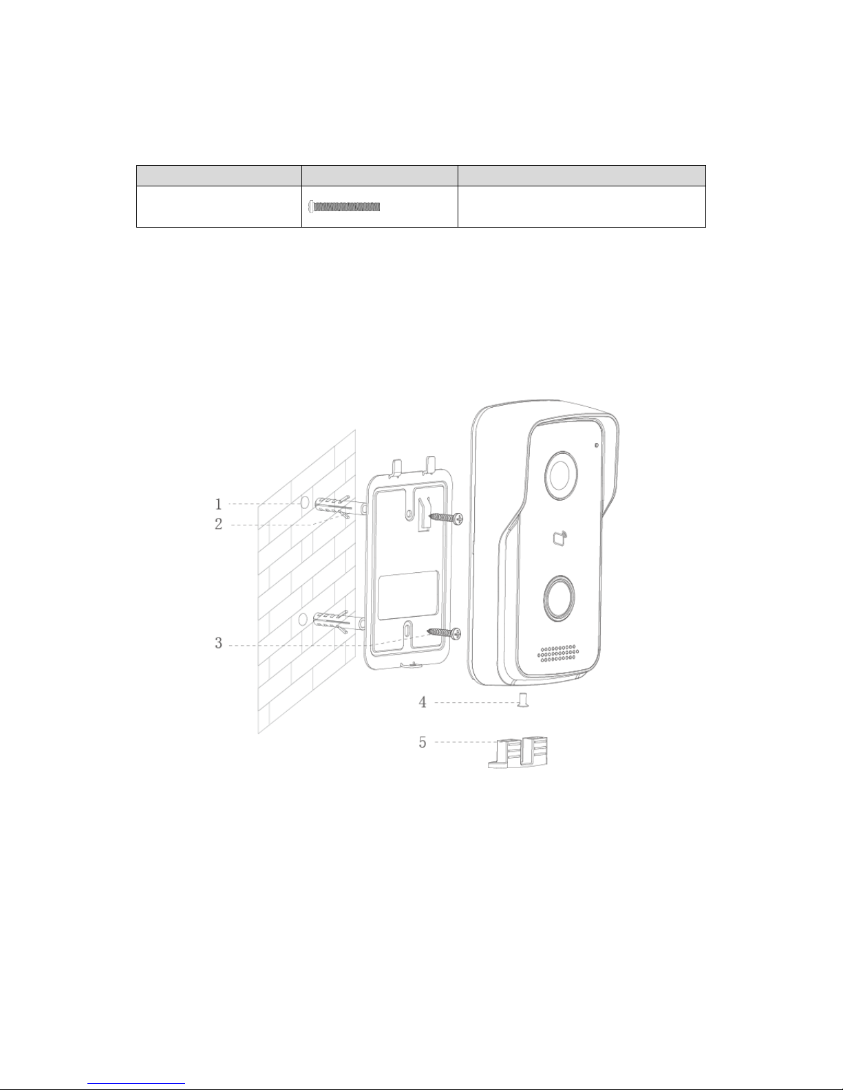
4.2.2 Installation Step
VTH installation is in Figure 4-2.
Figure 4-2
Steps:
Step 1. According to position of bracket, dig hole on installation surface (such as w al l).
Step 2. Insert expansion bolt in h ole you just dug.
Step 3. Fix bracket on designated position with screw.
Step 4. Fix device on bracket with screw.
Step 5. Install tail sealing element at device tail. Use two M4×30 screw pan head
machine screw to fix bracket on 86 box.

7
Note:
The recommended distance from device center to ground is 1.4m~1.6m.
4.3 Debug Device
4.3.1 Before Debugging
Warning:
Debugging personnel shal l be familiar w ith related materia ls, know devic e inst allation,
wiring and usage.
Debugging personnel check whether circuit has short circuit or open circuit or not.
Make sure circuit is normal, plug device to power.
After debugging end, cl ear up site (handle plugs, fix device and etc.)
Villa VTO default IP address is 192.168.1.110. Before you use the VTO, you must modify
its IP to be in the same network segment with the VTH.
Step to debug:
Step 1. Connect device to power, and power up.
Step 2. In PC browser, enter device default IP address 192.168.1.1 10. See Figure 4-3.
Figure 4-3
Step 3. Enter username and password.
Note:
Default username is “admin”. Default password is “admin”. Please refer to Ch 5.2.4.1
for setup.
 Loading...