

Dahua VTO2000A-C, VTO2000A-B, VTO2000A-K, VTO2000A-R, VTO2000A-F User Manual

Modular VTO
(Version 3.1)
User’s Manual
V1.0.1

Mandatory actions to be taken towards cybersecurity
1. Change Passwords and Use Strong Passwords:
The number one reason systems get “hacked” is due to having weak or default passwords. It is
recommended to change default passwords immediately and choose a strong password
whenever possible. A strong password should be made up of at least 8 characters and a
combination of special characters, numbers, and upper and lower case letters.
2. Update Firmware
As is standard procedure in the tech-industry, we recommend keeping NVR, DVR, and IP
camera firmware up-to-date to ensure the system is current with the latest security patches and
fixes.
“Nice to have” recommendations to improve your network security
1. Change Passwords Regularly
Regularly change the credentials to your devices to help ensure that only authorized users are
able to access the system.
2. Change Default HTTP and TCP Ports:
● Change default HTTP and TCP ports for systems. These are the two ports used to
communicate and to view video feeds remotely.
● These ports can be changed to any set of numbers between 1025-65535. Avoiding the
default ports reduces the risk of outsiders being able to guess which ports you are using.
3. Enable HTTPS/SSL:
Set up an SSL Certificate to enable HTTPS. This will encrypt all communication between your
devices and recorder.
4. Enable IP Filter:
Enabling your IP filter will prevent everyone, except those with specified IP addresses, from
accessing the system.
5. Change ONVIF Password:
On older IP Camera firmware, the ONVIF password does not change when you change the
system’s credentials. You will need to either update the camera’s firmware to the latest revision
or manually change the ONVIF password.
6. Forward Only Ports You Need:
Cybersecurity Recommendations
II

● Only forward the HTTP and TCP ports that you need to use. Do not forward a huge range of
numbers to the device. Do not DMZ the device's IP address.
● You do not need to forward any ports for individual cameras if they are all connected to a
recorder on site; just the NVR is needed.
7. Disable Auto-Login on SmartPSS:
Those using SmartPSS to view their system and on a computer that is used by multiple people
should disable auto-login. This adds a layer of security to prevent users without the appropriate
credentials from accessing the system.
8. Use a Different Username and Password for SmartPSS:
In the event that your social media, bank, email, etc. account is compromised, you would not
want someone collecting those passwords and trying them out on your video surveillance
system. Using a different username and password for your security system will make it more
difficult for someone to guess their way into your system.
9. Limit Features of Guest Accounts:
If your system is set up for multiple users, ensure that each user only has rights to features and
functions they need to use to perform their job.
10. UPnP:
● UPnP will automatically try to forward ports in your router or modem. Normally this would be a
good thing. However, if your system automatically forwards the ports and you leave the
credentials defaulted, you may end up with unwanted visitors.
● If you manually forwarded the HTTP and TCP ports in your router/modem, this feature should
be turned off regardless. Disabling UPnP is recommended when the function is not used in real
applications.
11. SNMP:
Disable SNMP if you are not using it. If you are using SNMP, you should do so only temporarily,
for tracing and testing purposes only.
12. Multicast:
Multicast is used to share video streams between two recorders. Currently there are no known
issues involving Multicast, but if you are not using this feature, deactivation can enhance your
network security.
13. Check the Log:
If you suspect that someone has gained unauthorized access to your system, you can check
the system log. The system log will show you which IP addresses were used to login to your
system and what was accessed.
14. Physically Lock Down the Device:
III

Ideally, you want to prevent any unauthorized physical access to your system. The best way to
achieve this is to install the recorder in a lockbox, locking server rack, or in a room that is
behind a lock and key.
15. Connect IP Cameras to the PoE Ports on the Back of an NVR:
Cameras connected to the PoE ports on the back of an NVR are isolated from the outside world
and cannot be accessed directly.
16. Isolate NVR and IP Camera Network
The network your NVR and IP camera resides on should not be the same network as your
public computer network. This will prevent any visitors or unwanted guests from getting access
to the same network the security system needs in order to function properly.
IV
Signal Words
Meaning
Indicates a high potential hazard which, if not avoided, will result
in death or serious injury.
Indicates a medium or low potential hazard which, if not avoided,
could result in slight or moderate injury.
Indicates a potential risk which, if not avoided, could result in
property damage, data loss, lower performance, or unpredictable
result.
Provides methods to help you solve a problem or save you time.
Provides additional information as the emphasis and supplement
to the text.
Foreword
General
This document mainly introduces product function, structure, networking, mounting process,
debugging process, WEB operation and technical parameters of modular VTO, which is
matched with Version 3.12 WEB interface.
Models
VTO2000A-C, VTO2000A-B, VTO2000A-K, VTO2000A-R and VTO2000A-F.
Device Upgrade
Please don’t cut off power supply during device upgrade. Power supply can be cut off only after
the device has completed upgrade and has rebooted.
General Description about Keys
OK: it is used to save the settings.
Default: it is used to restore all parameters at the present interface to default system
configurations.
Refresh: restore parameters at the present interface to present system configurations.
Safety Instructions
The following categorized signal words with defined meaning might appear in the Manual.
Revision History
V

No.
Version No.
Revision Content
Release Date
1
V1.0.0
First release
2017.10.31
2
V1.0.1
Add privacy protection notice
2018.05.23
Privacy Protection Notice
As the device user or data controller, you might collect personal data of others' such as face,
fingerprints, car plate number, Email address, phone number, GPS and so on. You need to be
in compliance with the local privacy protection laws and regulations to protect the legitimate
rights and interests of other people by implementing measures include but not limited to:
providing clear and visible identification to inform data subject the existence of surveillance
area and providing related contact.
About the Manual
The Manual is for reference only. If there is inconsistency between the Manual and the
actual product, the actual product shall prevail.
We are not liable for any loss caused by the operations that do not comply with the Manual.
The Manual would be updated according to the latest laws and regulations of related
regions. For detailed information, see the paper User's Manual, CD-ROM, QR code or our
official website. If there is inconsistency between paper User's Manual and the electronic
version, the electronic version shall prevail.
All the designs and software are subject to change without prior written notice. The product
updates might cause some differences between the actual product and the Manual. Please
contact the customer service for the latest program and supplementary documentation.
There still might be deviation in technical data, functions and operations description, or
errors in print. If there is any doubt or dispute, please refer to our final explanation.
Upgrade the reader software or try other mainstream reader software if the Guide (in PDF
format) cannot be opened.
All trademarks, registered trademarks and the company names in the Manual are the
properties of their respective owners.
Please visit our website, contact the supplier or customer service if there is any problem
occurred when using the device.
If there is any uncertainty or controversy, please refer to our final explanation.
VI

Important Safeguards and Warnings
The following description is the correct application method of the device. Please read the
manual carefully before use, in order to prevent danger and property loss. Strictly conform to
the manual during application and keep it properly after reading.
Operating Requirement
Please don’t place and install the device in an area exposed to direct sunlight or near heat
generating device.
Please don’t install the device in a humid, dusty or fuliginous area.
Please keep its horizontal installation, or install it at stable places, and prevent it from
falling.
Please don’t drip or splash liquids onto the device; don’t put on the device anything filled
with liquids, in order to prevent liquids from flowing into the device.
Please install the device at well-ventilated places; don’t block its ventilation opening.
Use the device only within rated input and output range.
Please don’t dismantle the device arbitrarily.
Please transport, use and store the device within allowed humidity and temperature range.
Power Requirement
The product shall use electric wires (power wires) recommended by this area, which shall
be used within its rated specification!
Please use power supply that meets SELV (safety extra low voltage) requirements, and
supply power with rated voltage that conforms to Limited Power Source in IEC60950-1. For
specific power supply requirements, please refer to device labels.
Appliance coupler is a disconnecting device. During normal use, please keep an angle that
facilitates operation.
VII

Cybersecurity Recommendations ........................................................................................................ II
Foreword ................................................................................................................................................. V
Important Safeguards and Warnings ................................................................................................. VII
1 Product Overview ............................................................................................................................... 1
1.1 Product Profile ............................................................................................................................... 1
1.2 Product Function ........................................................................................................................... 1
2 Product Structure ............................................................................................................................... 3
2.1 Camera Module............................................................................................................................. 3
2.2 Button Module ............................................................................................................................... 5
2.3 Keyboard Module (with Braille) ..................................................................................................... 7
2.4 Card Swiping Module .................................................................................................................... 7
2.5 Fingerprint Module ........................................................................................................................ 8
2.6 Blank Module ................................................................................................................................ 9
3 Networking Diagram ......................................................................................................................... 11
3.1 One-to-one Scene ........................................................................................................................ 11
3.2 One-to-many Scene ..................................................................................................................... 11
3.3 Group Call Scene ........................................................................................................................ 12
4 Device Mounting ............................................................................................................................... 14
4.1 Surface Mounting ........................................................................................................................ 14
4.2 Flush Mounting ............................................................................................................................ 16
5 Device Debugging ............................................................................................................................ 18
5.1 Debugging Settings ..................................................................................................................... 18
5.1.1 VTO Settings..................................................................................................................... 18
5.1.2 VTH Settings (Version 3.1) ............................................................................................... 24
5.1.3 VTH Settings (Version 4.0) ............................................................................................... 28
5.2 Debugging Verification ................................................................................................................ 33
5.2.1 Verification with Version 3.1 VTH ..................................................................................... 33
5.2.2 Verification with Version 4.0 VTH ..................................................................................... 35
6 Basic Function .................................................................................................................................. 37
6.1 Call Function ............................................................................................................................... 37
6.1.1 Call Management Centre .................................................................................................. 37
6.1.2 Single Call of VTH ............................................................................................................ 38
6.1.3 Group Call ......................................................................................................................... 40
6.2 Unlock Function .......................................................................................................................... 42
6.2.1 Remote Unlock at VTH/VTS ............................................................................................. 42
6.2.2 Open Door at WEB Interface ............................................................................................ 42
6.2.3 Unlock with IC Card .......................................................................................................... 43
6.2.4 Unlock with Exit Button ..................................................................................................... 43
6.2.5 Unlock with Password ...................................................................................................... 43
6.3 Issue Card ................................................................................................................................... 44
6.4 Monitoring Function .................................................................................................................... 45
Table of Contents
VIII

6.5 Tamper Switch ............................................................................................................................. 46
6.6 Restore Backup........................................................................................................................... 46
7 WEB Config .......................................................................................................................................... 48
7.1 Initialization ................................................................................................................................. 48
7.2 Reset the Password .................................................................................................................... 49
7.3 System Login .............................................................................................................................. 51
7.4 User Manager ............................................................................................................................. 52
7.4.1 Add User ........................................................................................................................... 52
7.4.2 Modify User ....................................................................................................................... 53
7.4.3 Delete User ....................................................................................................................... 55
7.5 Network Parameter Config.......................................................................................................... 55
7.5.1 Network Config ................................................................................................................. 55
7.5.2 FTP Server ........................................................................................................................ 56
7.5.3 Port ................................................................................................................................... 56
7.5.4 DDNS Server .................................................................................................................... 58
7.5.5 P2P ................................................................................................................................... 59
7.5.6 HTTPS Setting .................................................................................................................. 59
7.5.7 UPnP ................................................................................................................................. 60
7.5.8 IP Purview ......................................................................................................................... 62
7.6 LAN Config .................................................................................................................................. 63
7.7 Local Parameter Config .............................................................................................................. 65
7.7.1 Local Config ...................................................................................................................... 65
7.7.2 Facade Layout .................................................................................................................. 65
7.7.3 Access Manager ............................................................................................................... 68
7.7.4 Sound Control ................................................................................................................... 70
7.7.5 Talk Manager .................................................................................................................... 70
7.7.6 System Time ..................................................................................................................... 71
7.7.7 Config Manager ................................................................................................................ 72
7.8 Indoor Manager ........................................................................................................................... 72
7.8.1 Add VTH ............................................................................................................................ 73
7.8.2 Modify VTH ....................................................................................................................... 73
7.8.3 Delete VTH ....................................................................................................................... 74
7.8.4 QR Code ........................................................................................................................... 74
7.8.5 Config Manager ................................................................................................................ 75
7.8.6 Card Manager ................................................................................................................... 75
7.9 Video Set ..................................................................................................................................... 77
7.9.1 Video Set .......................................................................................................................... 77
7.9.2 Audio Set........................................................................................................................... 78
7.10 IPC Info ..................................................................................................................................... 79
7.10.1 Add One IPC ................................................................................................................... 79
7.10.2 Delete .............................................................................................................................. 80
7.10.3 Batch Import ................................................................................................................... 81
7.10.4 Batch Export ................................................................................................................... 81
7.11 Fingerprint Manager .................................................................................................................. 81
7.11.1 Collect Fingerprint ........................................................................................................... 81
7.11.2 Modify Fingerprint Info .................................................................................................... 82
7.11.3 Remove Fingerprint ........................................................................................................ 82
IX

7.11.4 Import Fingerprint Info..................................................................................................... 82
7.11.5 Export Fingerprint Info .................................................................................................... 82
7.12 Info Search ................................................................................................................................ 83
7.12.1 Call History ..................................................................................................................... 83
7.12.2 Alarm Record .................................................................................................................. 83
7.12.3 Unlock Record ................................................................................................................ 83
7.13 Reboot Device........................................................................................................................... 84
7.14 Logout ....................................................................................................................................... 84
8 FAQ ....................................................................................................................................................... 85
Appendix 1 Technical Parameters ........................................................................................................ 86
Appendix 1.1 VTO2000A-C .............................................................................................................. 86
Appendix 1.2 VTO2000A-B/VTO2000A-K/VTO2000A-R /VTO2000A-F .......................................... 87
Appendix 2 Accessory Specification ................................................................................................... 88
Appendix 2.1 Specification of Network Cable ................................................................................... 88
Appendix 2.2 Specification of Extension Power Cord ...................................................................... 88
Appendix 2.3 Specification of Embedded Box .................................................................................. 88
X

1 Product Overview
1.1 Product Profile
Modular VTO consists of camera module, one-button module, three-button module, five-button
module, keyboard module, card swiping module and fingerprint module. Camera module is
indispensable, whereas other modules can be matched flexibly, and can combine with VTH,
VTS and platform to establish a video intercom system. Support video call between a visitor
and a resident, group call, emergency call, unlock, info sending, video preview and record
search. It is mainly applied in apartments and villas, and matched with management platform to
realize all-round anti-theft, disaster prevention and monitoring function.
1.2 Product Function
Video Intercom
Call VTH users and realize video talk.
Group Call
Call multiple VTH users at one VTO simultaneously.
Be Monitored
VTH or Management Center can monitor VTO image, and support max. 6-channel video
stream monitoring.
Emergency Call
Press the key to call the Center in case of an emergency.
Auto Snapshot
Unlock
Snapshot pictures automatically during unlock or talk, and store them in FTP.
Realize unlock with card, fingerprint, password and remote unlock.
1

Alarm
Support tamper alarm, door sensor alarm and alarm of unlock with duress password.
Meanwhile, report the alarm info to Management Center.
Record Search
Search call records, alarm records and unlock records.
2
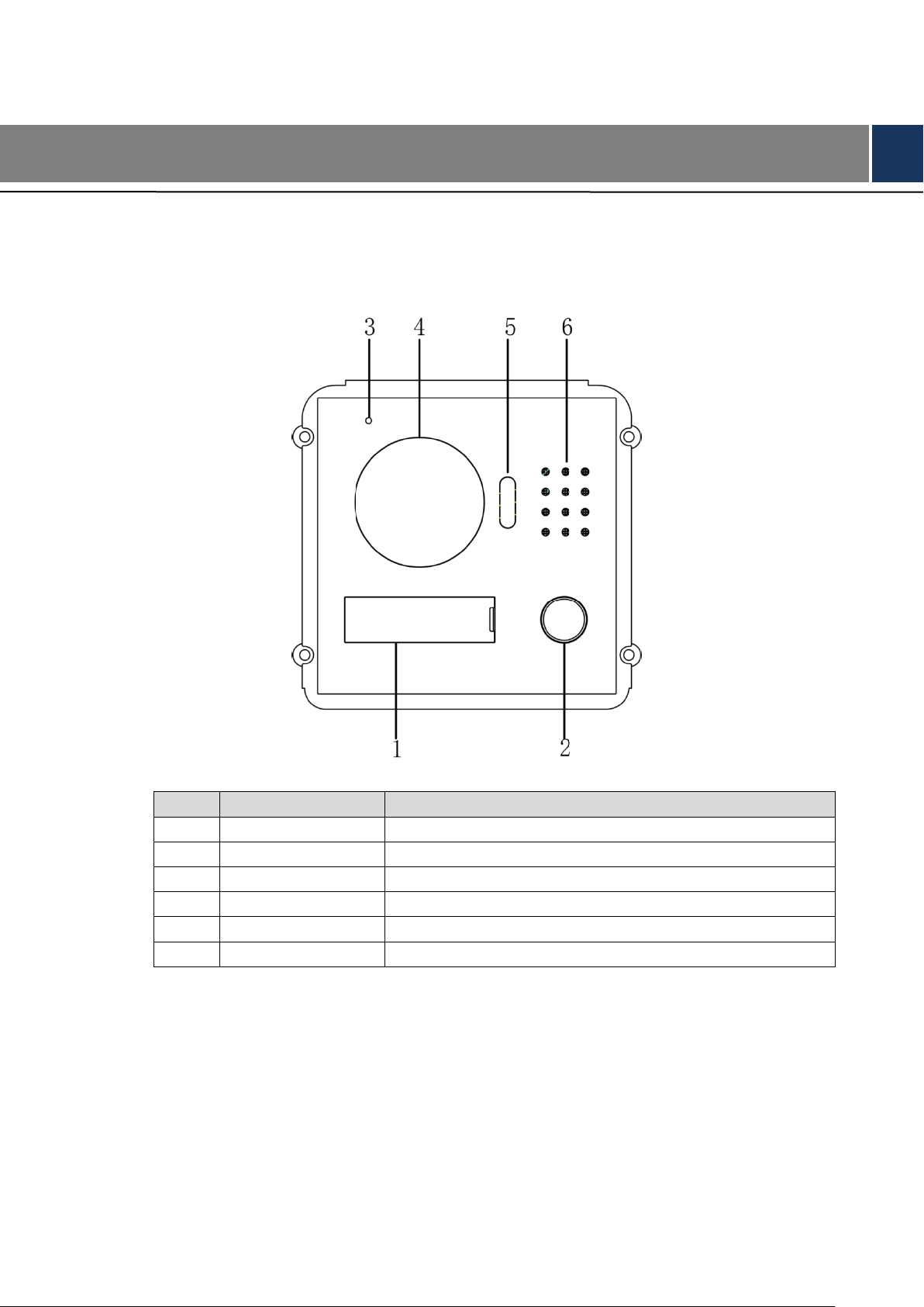
No.
Name
Description
1
User directory
Display user info.
2
Call key
Call the user or management centre.
3
Microphone
Audio input.
4
Camera
Monitor the door area, with adjustable angle.
5
Fill-in light
Provide fill-in light for camera in case of insufficient light.
6
Speaker
Audio output.
2 Product Structure
2.1 Camera Module
Figure 2-1
Table 2-1
3
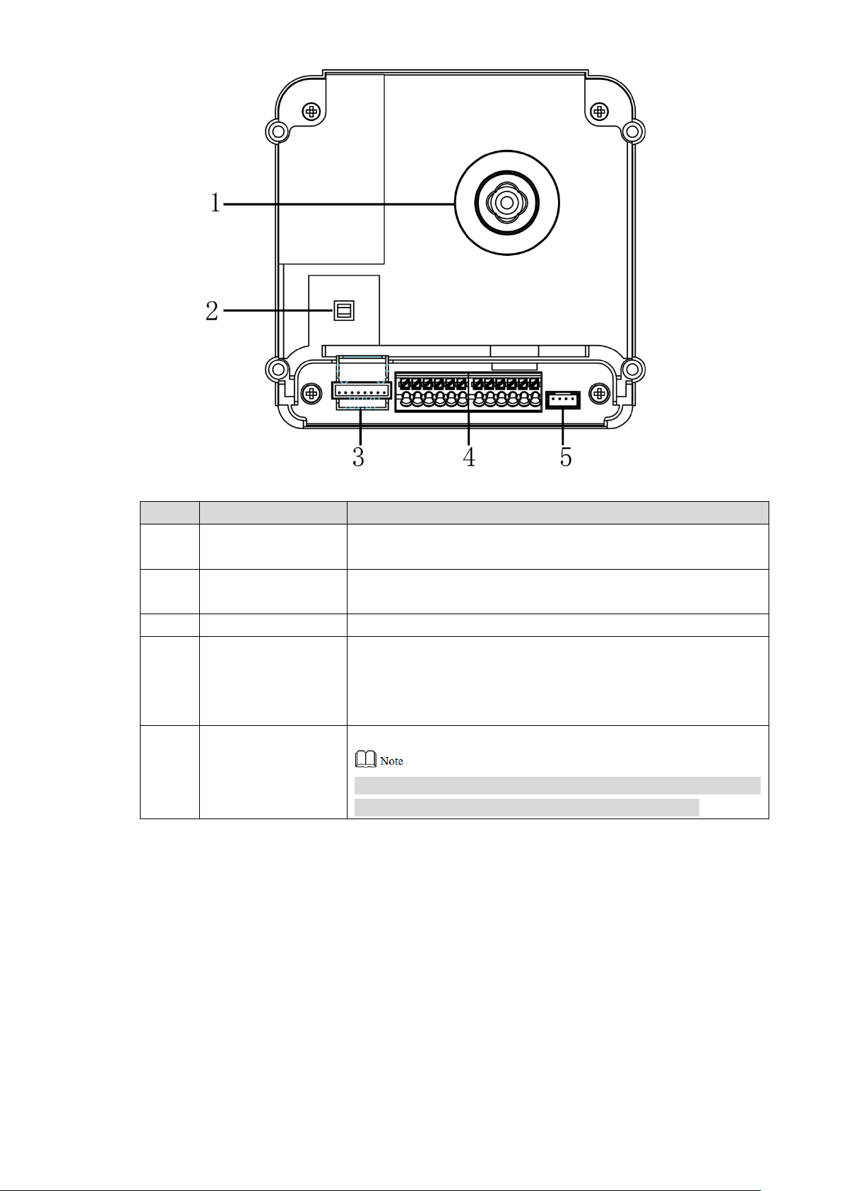
No.
Name
Description
1
Camera angle
adjusting column
Adjust camera angle.
2
Tamper switch
When VTO is detached from the wall forcibly, give out alarm
sound and report alarm info to management centre.
3
Network port
Connect network cable (RJ45 plug) through a connection line.
4
User port
Provide power port, lock port, door sensor feedback port and
exit button port to connect power supply, electric control lock,
solenoid lock and exit button. Wiring method is shown in
Figure 2-3 and Figure 2-4.
5
Cascade
connection port
Connect other modules.
In case of cascade connection of multiple modules, modules
shall adopt cascade connection between each other.
Figure 2-2
Table 2-2
4
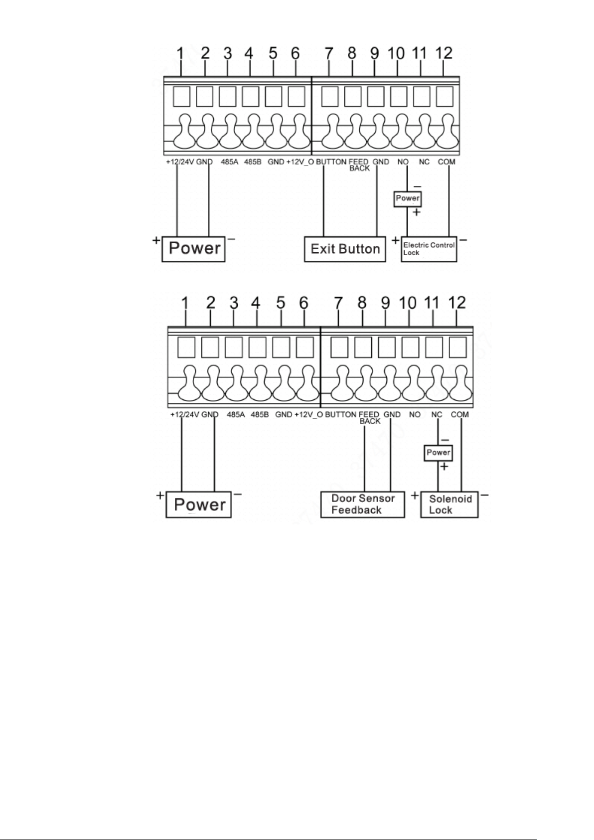
Figure 2-3
2.2 Button Module
Button module consists of one-button module, three-button module and five-button module;
their functions are the same, although button quantity is different. Take “three-button module”
for example.
Figure 2-4
5
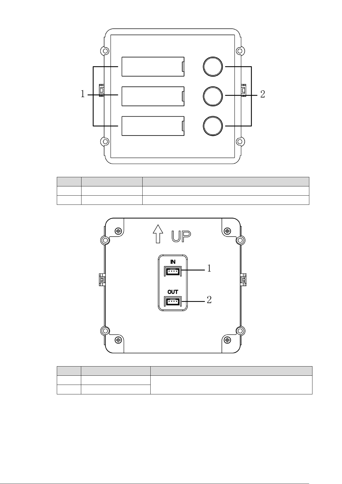
No.
Name
Description
1
User directory
Display user info according to buttons.
2
Call key
Call the VTH.
No.
Name
Description
1
Cascade input port
Connect other modules.
2
Cascade output port
Figure 2-5
Table 2-3
Figure 2-6
Table 2-4
6
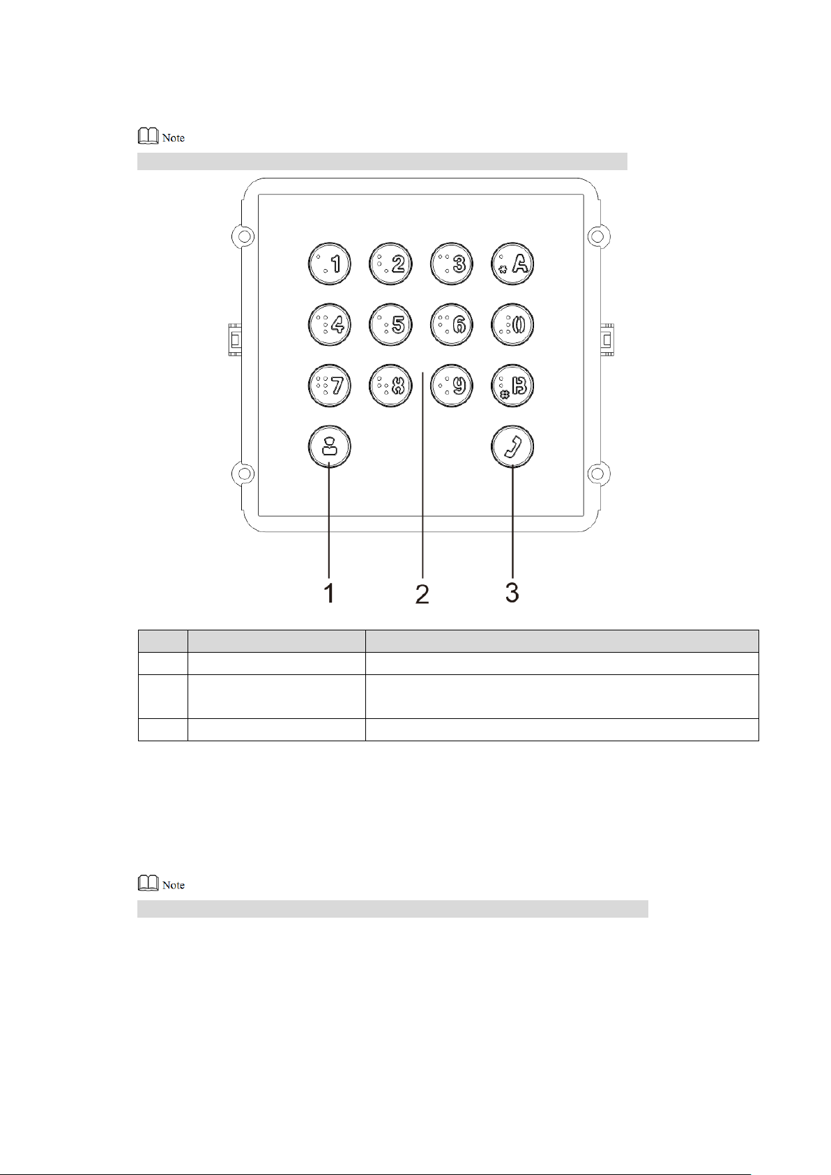
No.
Name
Description
1
Call management centre
Call management centre.
2
Numeric key
Input the password. For example, unlock password is
123456. Please input “#+ unlock password +#”.
3
Call key
Call the VTH.
2.3 Keyboard Module (with Braille)
Rear panel of keyboard module is the same as rear panel of button module.
2.4 Card Swiping Module
Rear panel of card swiping module is the same as rear panel of button module.
Figure 2-7
Table 2-5
7
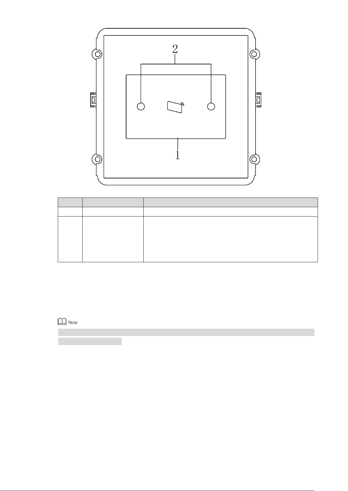
No.
Name
Description
1
Card swiping area
It is valid to swipe the card here.
2
Proximity sensor
When a person is about 1m away from the device, the device
will sense the person’s approaching. Backlights of display
screens of all modules and the keyboard will be turned on
automatically. And they will turn off automatically after the
person leaves.
2.5 Fingerprint Module
Rear panels of fingerprint module and button module have different port positions, but port
functions are the same.
Figure 2-8
Table 2-6
8
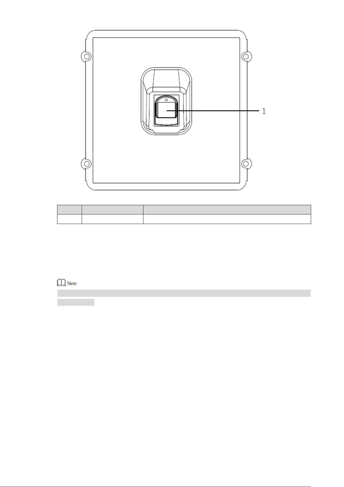
No.
Name
Description
1
Fingerprint module
The user inputs a fingerprint or unlocks with a fingerprint.
2.6 Blank Module
Rear panels of blank module and button module have different port positions, but port functions
are the same.
Figure 2-9
Table 2-7
9
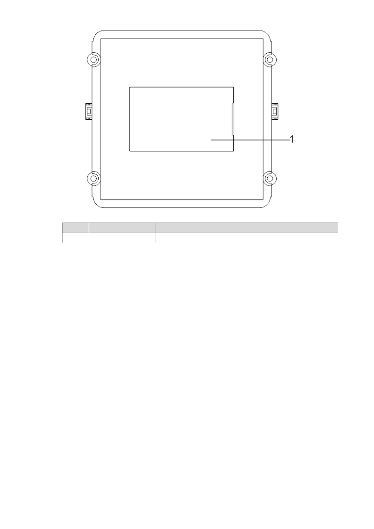
No.
Name
Description
1
User directory
Display user info according to buttons.
Figure 2-10
Table 2-8
10
Modular VTO consists of 9 modules at most. Camera module is indispensable, whereas max. 1
keyboard, card swiping, fingerprint module can be included.
3 Networking Diagram
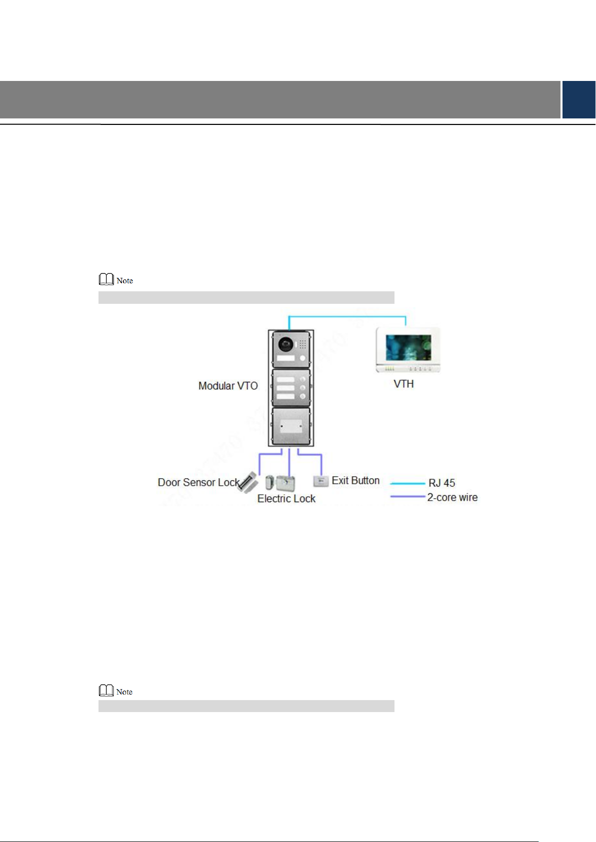
3.1 One-to-one Scene
Modular VTO connects with VTH directly. A visitor presses call key on VTO to call the resident
(VTH) or Management Center. Networking diagram is shown in Figure 3-1.
If keyboard module is connected, dial VTH room number to call.
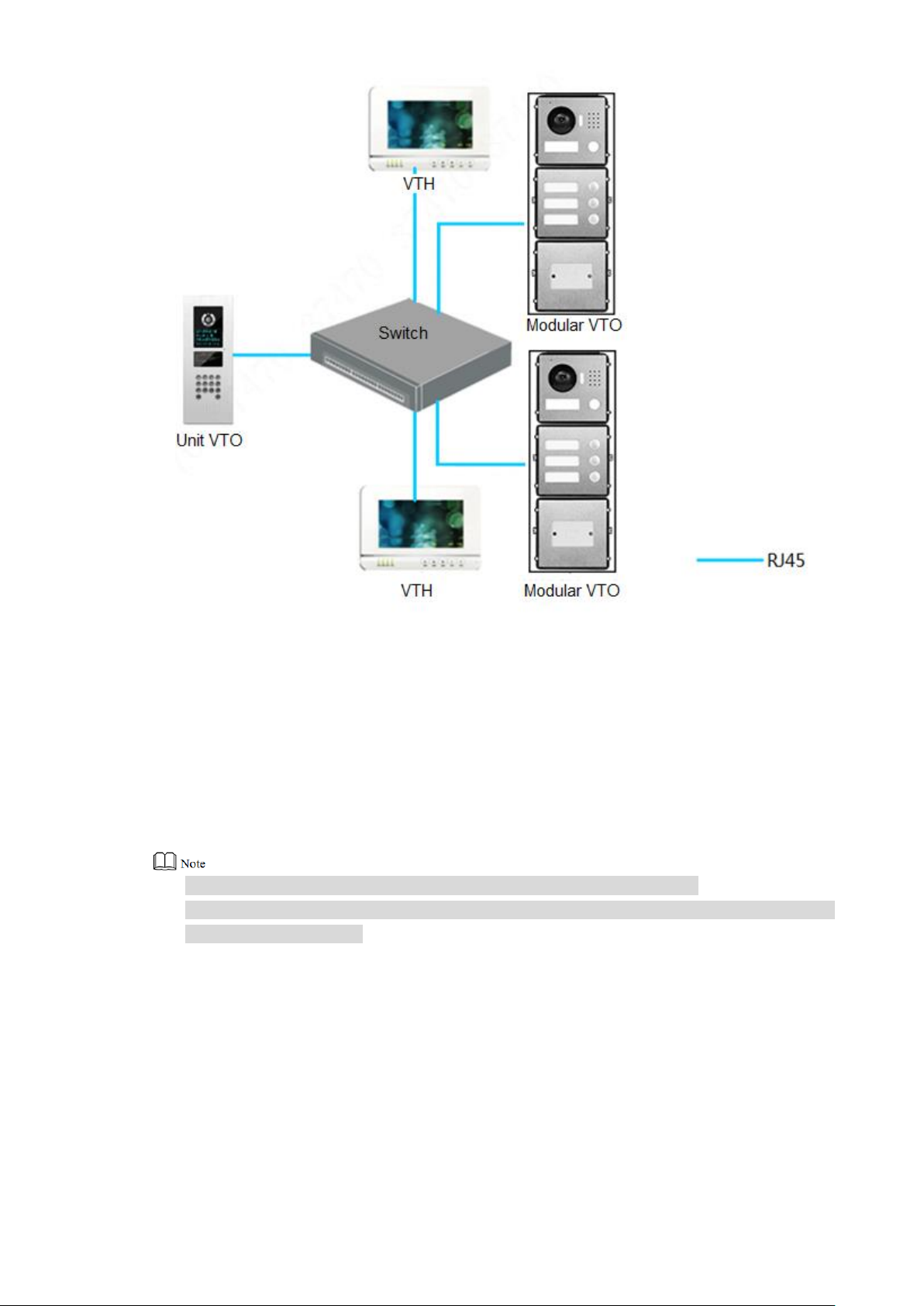
3.2 One-to-many Scene
Generally, unit VTO is installed at the gate of apartment building, whereas modular VTO is
installed at the resident’s gate. The operation process is as follows.
The visitor calls any resident with unit VTO. Step 1
The resident’s VTH rings. After unlocking, the visitor goes into the apartment building.
Call the resident with modular VTO, and ask the resident to unlock the house. Step 2
If keyboard module is connected, dial VTH room number to call.
Networking diagram is shown in Figure 3-2.
Figure 3-1
11
3.3 Group Call Scene
When the visitor presses call key on modular VTO, multiple VTHs ring at the same time; the
resident can pick up, hang up or unlock on any VTH.
Networking diagram is shown in Figure 3-3.
If keyboard module is connected, dial master VTH room number to call.
VTH consists of master VTH and extension VTH. There is 1 master VTH at most and 5
extension VTHs at most.
Figure 3-2
12
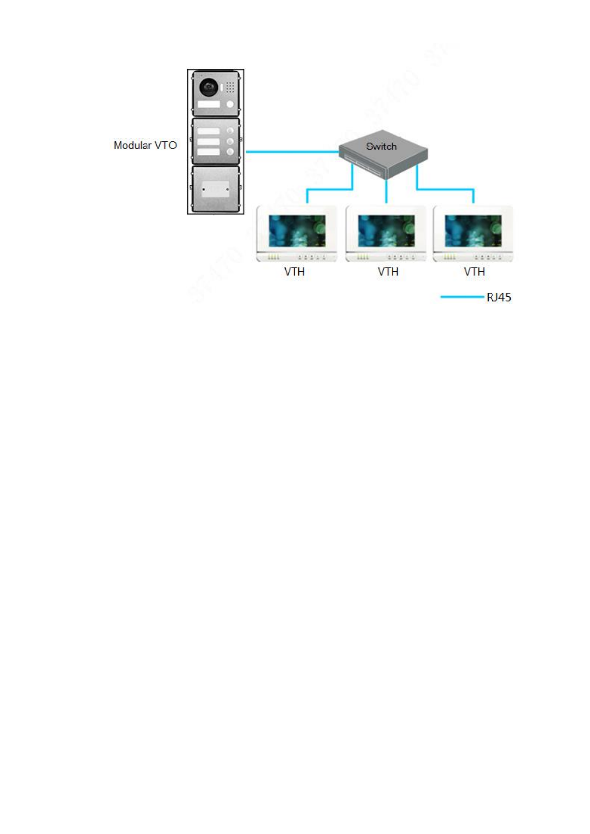
Figure 3-3
13

Modular VTO consists of single module mounting, double module mounting and 3-module
mounting. Take 3-module mounting for example.
When leaving factory by default, visiting cards and card cover have been included in the
attachment.
When power-on after mounting, please ensure that all modules have been connected;
otherwise, they fail to work normally.
Before installation of surface mounting box and flush mounting box, cables in the wall shall
go through the bracket or flush mounting box.
4 Device Mounting
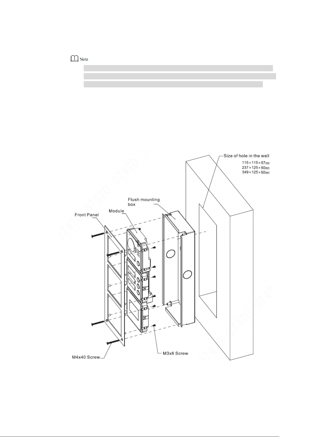
4.1 Surface Mounting
Drill holes according to hole positions of surface mounting box, and put expansion pipe Step 1
in place.
Fix surface mounting box onto the wall with ST3×18 screws. Step 2
Fix every module onto front panel with M3×6 screws. Step 3
Connect cables. Please refer to “2 Product Structure”. Step 4
Fix the front panel onto surface mounting box with M4×40 screws. Step 5
Apply glue between surface mounting box and the wall. Step 6
Write room number or the user’s name on the visiting card, and insert it into user Step 7
directory.
14
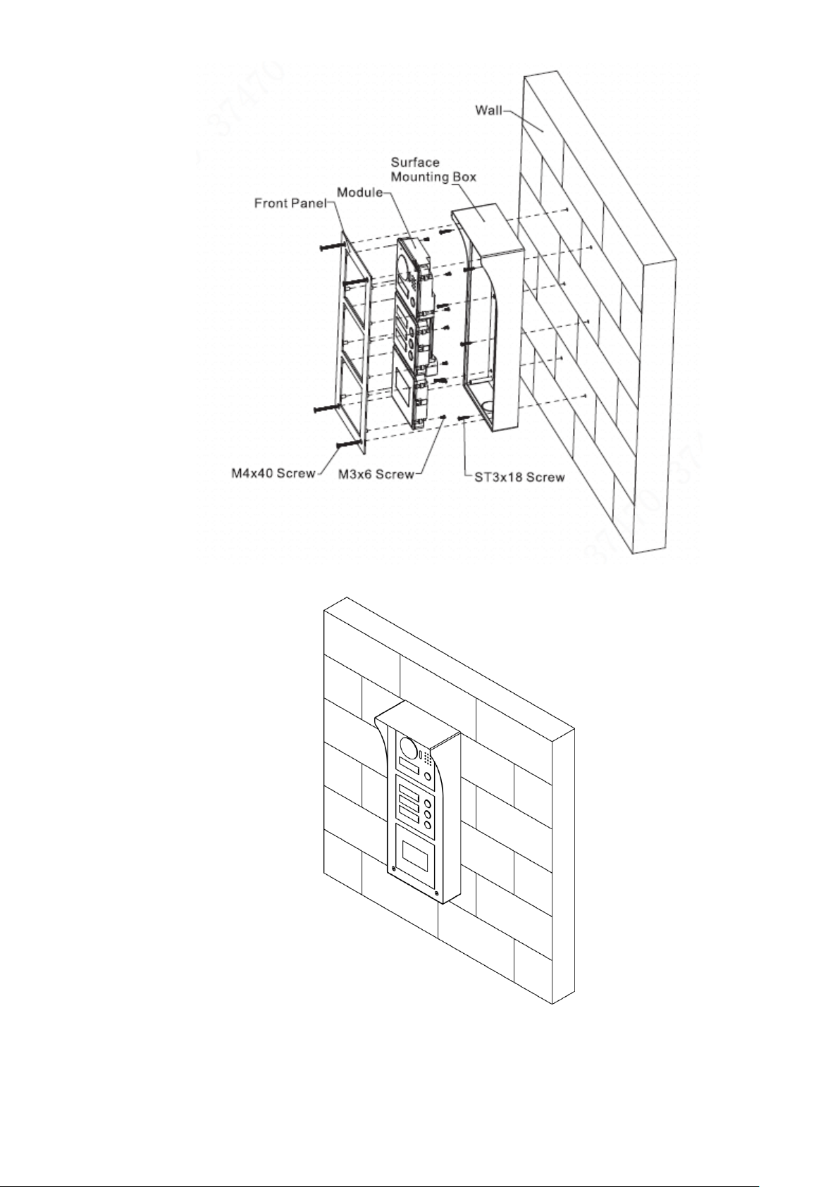
Figure 4-1
Figure 4-2
15
4.2 Flush Mounting
Dig a hole in the wall. Step 1
Regarding single module mounting, hole dimension is 115mm×115mm×57mm.
Regarding double module mounting, hole dimension is 237mm×125mm×50mm.
Regarding 3-module mounting, hole dimension is 349mm×125mm×50mm.
Embed flush mounting box into the wall; ensure that box edge clings to the wall. Step 2
Fix every module onto front panel with M3×6 screws. Step 3
Connect cables. Please refer to “2 Product Structure”. Step 4
Fix the front panel onto flush mounting box with M4×40 screws. Step 5
Apply glue among front panel, flush mounting box and the wall. Step 6
Write room number or the user’s name on the visiting card, and insert it into user Step 7
directory.
Figure 4-3
16
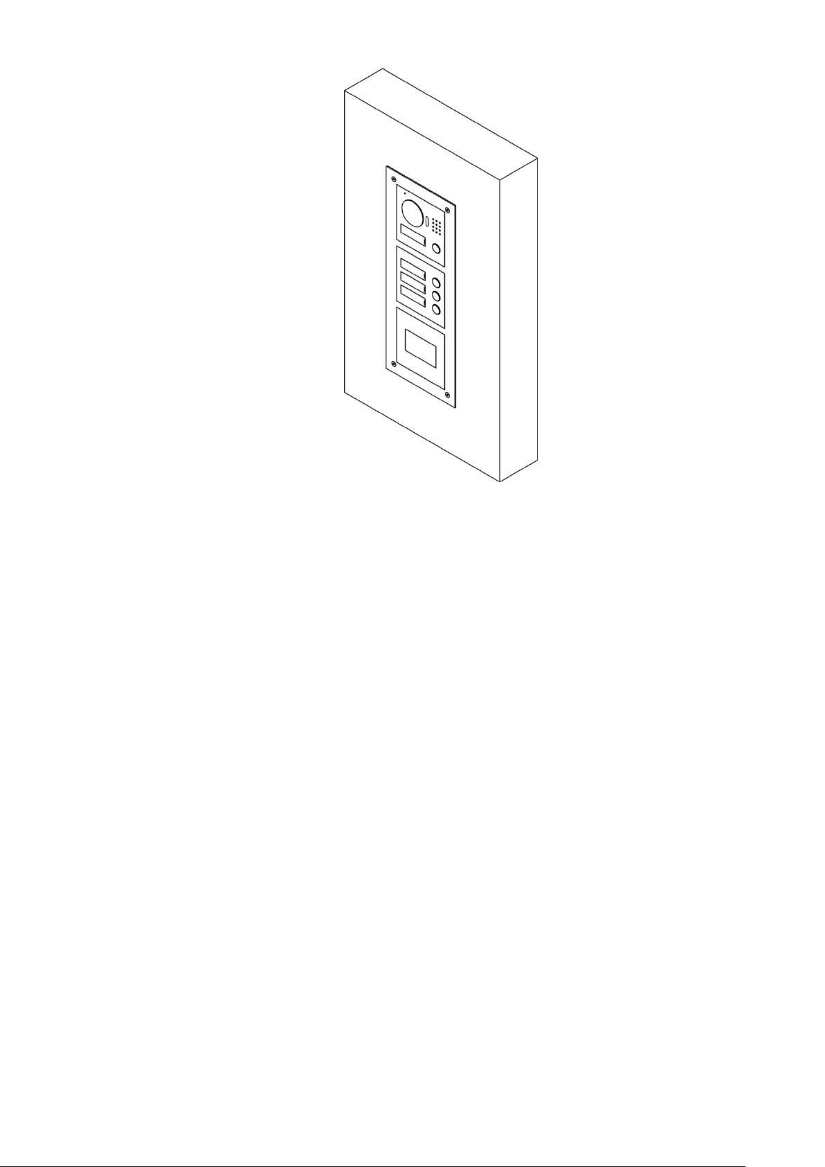
Figure 4-4
17
5 Device Debugging
5.1 Debugging Settings
5.1.1 VTO Settings
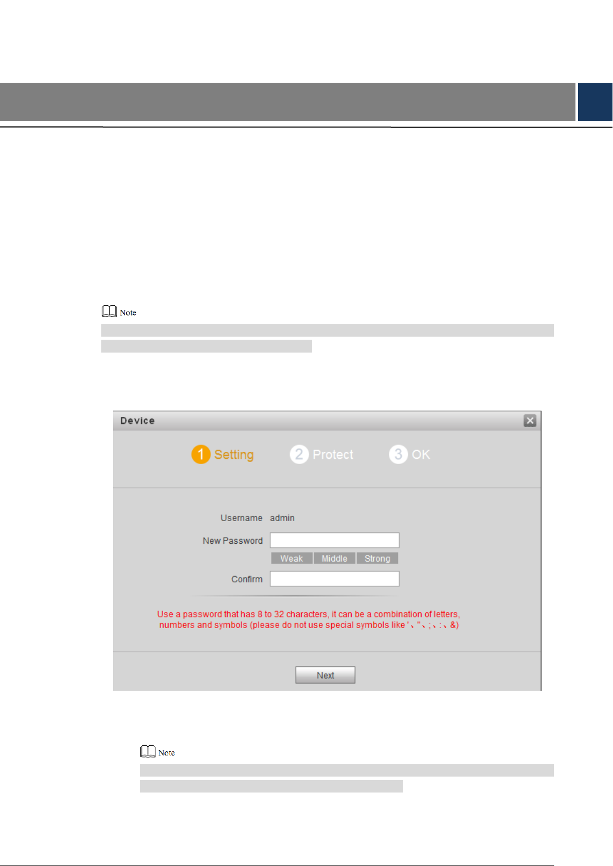
5.1.1.1 Initialization
For the first time, please initialize login password.
Please ensure that default IP addresses of PC and VTO are in the same network segment.
Default IP address of VTO is 192.168.1.110.
Connect power supply of VTO, and power on. Step 1
Enter default IP address of VTO at the address bar of PC browser. Step 2
The system displays “Setting” interface, as shown in Figure 5-1.
Figure 5-1
Enter “New Password” and “Confirm”, and click “Next”. Step 3
The system displays “Protect” interface, as shown in Figure 5-2.
This password is used to login WEB interface. It shall be at least 8 characters, and shall
include at least two types of number, letter and symbol.
18

Figure 5-2
Select “Email” and enter your Email address. Step 4
This Email address is used to reset the password, so it is recommended that it should
be set.
Click “Next”. Step 5
The system displays “OK” interface, as shown in Figure 5-3 错误!未找到引用源。, and
shows “Device succeeded!”
Figure 5-3
Click “OK”. Step 6
The system displays WEB login interface, as shown in Figure 5-4.
19
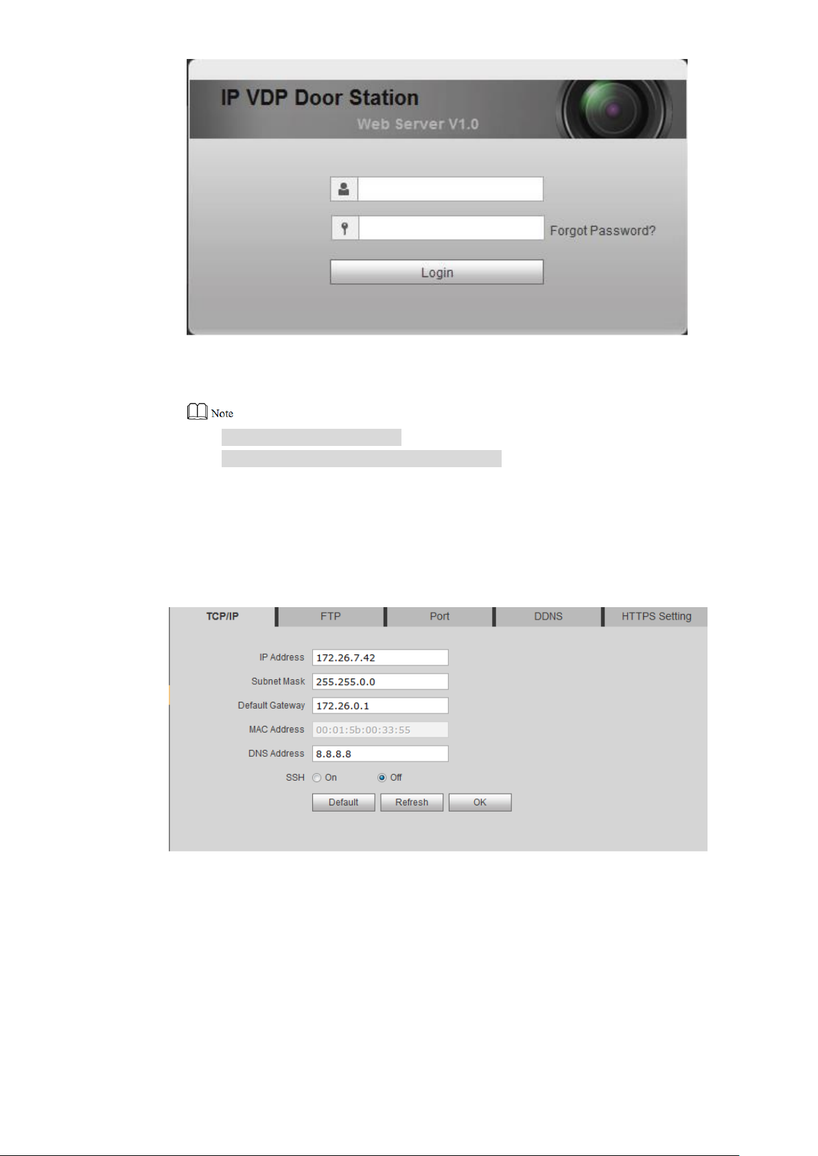
Figure 5-4
Enter user name and password, and click “Login”. Step 7
Log in the WEB interface of the device.
Default user name is admin.
Password is the one set during initialization.
5.1.1.2 Modify Device Network
Modify IP address of VTO to the planned IP address.
Select “System Config> Network Config> TCP/IP”. Step 1
The system displays “TCP/IP” interface, as shown in Figure 5-5.
Enter the planned “IP Address”, “Subnet Mask” and “Default Gateway”, and click “OK”. Step 2
After modification is completed, VTO reboots automatically, while the following two
cases occur at WEB interface.
If PC is in the planned network segment, WEB interface jumps to new IP login
interface automatically.
If PC is not in the planned network segment, login will be failed. Please add PC to
the planned network segment and login WEB interface again.
Figure 5-5
20
 Loading...