

Dahua VTO1210B-X, VTO1210C-X, VTO1210A-X, VTO1220A, VTO1220BW Quick Start Manual

Unit VTO
(Version 4.3)
Quick Start Guide
V1.0.1

Cybersecurity Recommendations II
Cybersecurity Recommendations
Mandatory actions to be taken towards cybersecurity
1. Change Passwords and Use Strong Passwords:
The number one reason systems get “hacked” is due to having weak or default passwords. It is
recommended to change default passwords immediately and choose a strong password
whenever possible. A strong password should be made up of at least 8 characters and a
combination of special characters, numbers, and upper and lower case letters.
2. Update Firmware
As is standard procedure in the tech-industry, we recommend keeping NVR, DVR, and IP
camera firmware up-to-date to ensure the system is current with the latest security patches and
fixes.
“Nice to have” recommendations to improve your network security
1. Change Passwords Regularly
Regularly change the credentials to your devices to help ensure that only authorized users are
able to access the system.
2. Change Default HTTP and TCP Ports:
● Change default HTTP and TCP ports for systems. These are the two ports used to
communicate and to view video feeds remotely.
● These ports can be changed to any set of numbers between 1025-65535. Avoiding the default
ports reduces the risk of outsiders being able to guess which ports you are using.
3. Enable HTTPS/SSL:
Set up an SSL Certificate to enable HTTPS. This will encrypt all communication between your
devices and recorder.
4. Enable IP Filter:
Enabling your IP filter will prevent everyone, except those with specified IP addresses, from
accessing the system.
5. Change ONVIF Password:
On older IP Camera firmware, the ONVIF password does not change when you change the
system’s credentials. You will need to either update the camera’s firmware to the latest revision
or manually change the ONVIF password.
6. Forward Only Ports You Need:

Cybersecurity Recommendations III
● Only forward the HTTP and TCP ports that you need to use. Do not forward a huge range of
numbers to the device. Do not DMZ the device's IP address.
● You do not need to forward any ports for individual cameras if they are all connected to a
recorder on site; just the NVR is needed.
7. Disable Auto-Login on SmartPSS:
Those using SmartPSS to view their system and on a computer that is used by multiple people
should disable auto-login. This adds a layer of security to prevent users without the appropriate
credentials from accessing the system.
8. Use a Different Username and Password for SmartPSS:
In the event that your social media, bank, email, etc. account is compromised, you would not
want someone collecting those passwords and trying them out on your video surveillance
system. Using a different username and password for your security system will make it more
difficult for someone to guess their way into your system.
9. Limit Features of Guest Accounts:
If your system is set up for multiple users, ensure that each user only has rights to features and
functions they need to use to perform their job.
10. UPnP:
● UPnP will automatically try to forward ports in your router or modem. Normally this would be
a good thing. However, if your system automatically forwards the ports and you leave the
credentials defaulted, you may end up with unwanted visitors.
● If you manually forwarded the HTTP and TCP ports in your router/modem, this feature should
be turned off regardless. Disabling UPnP is recommended when the function is not used in real
applications.
11. SNMP:
Disable SNMP if you are not using it. If you are using SNMP, you should do so only temporarily,
for tracing and testing purposes only.
12. Multicast:
Multicast is used to share video streams between two recorders. Currently there are no known
issues involving Multicast, but if you are not using this feature, deactivation can enhance your
network security.
13. Check the Log:
If you suspect that someone has gained unauthorized access to your system, you can check
the system log. The system log will show you which IP addresses were used to login to your
system and what was accessed.
14. Physically Lock Down the Device:

Cybersecurity Recommendations IV
Ideally, you want to prevent any unauthorized physical access to your system. The best way to
achieve this is to install the recorder in a lockbox, locking server rack, or in a room that is behind
a lock and key.
15. Connect IP Cameras to the PoE Ports on the Back of an NVR:
Cameras connected to the PoE ports on the back of an NVR are isolated from the outside world
and cannot be accessed directly.
16. Isolate NVR and IP Camera Network
The network your NVR and IP camera resides on should not be the same network as your public
computer network. This will prevent any visitors or unwanted guests from getting access to the
same network the security system needs in order to function properly.

Regulatory Information V
Regulatory Information
The regulatory information herein might vary according to the model you purchased. Some
information is only applicable for the country or region where the product is sold.
FCC Information
Changes or modifications not expressly approved by the party responsible for compliance could
void the user's authority to operate the equipment.
FCC conditions:
This device complies with part 15 of the FCC Rules. Operation is subject to the following two
conditions:
This device may not cause harmful interference.
This device must accept any interference received, including interference that may cause
undesired operation.
FCC compliance:
This equipment has been tested and found to comply with the limits for a digital device, pursuant
to part 15 of the FCC Rules. This equipment generate, uses and can radiate radio frequency
energy and, if not installed and used in accordance with the instructions, may cause harmful
interference to radio communication.
For class A device, these limits are designed to provide reasonable protection against
harmful interference in a commercial environment. Operation of this equipment in a
residential area is likely to cause harmful interference in which case the user will be required
to correct the interference at his own expense.
For class B device, these limits are designed to provide reasonable protection against
harmful interference in a residential installation. However, there is no guarantee that
interference will not occur in a particular installation. If this equipment does cause harmful
interference to radio or television reception, which can be determined by turning the
equipment off and on, the user is encouraged to try to correct the interference by one or
more of the following measures:
● Reorient or relocate the receiving antenna.
● Increase the separation between the equipment and receiver.
● Connect the equipment into an outlet on a circuit different from that to which the receiver
is connected.
● Consult the dealer or an experienced radio/TV technician for help.
Foreword VI
Foreword
General
This Guide introduces the structure, mounting process, and basic configuration of the device.
Safety Instructions
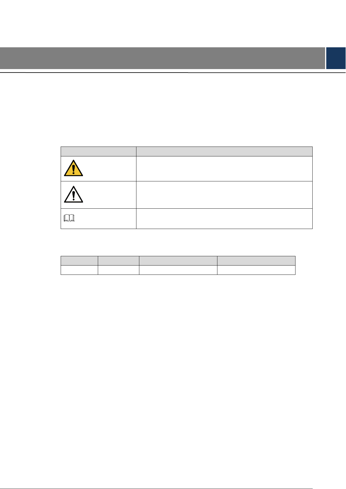
The following categorized signal words with defined meaning might appear in the Guide.
Signal Words
Meaning
WARNING
Indicates a medium or low potential hazard which, if not
avoided, could result in slight or moderate injury.
CAUTION
Indicates a potential risk which, if not avoided, could result in
property damage, data loss, lower performance, or
unpredictable result.
NOTE
Provides additional information as the emphasis and
supplement to the text.
Revision History
No.
Version
Revision Content
Release Date
1
V1.0.0
First release
September, 2018
Privacy Protection Notice
As the device user or data controller, you might collect personal data of others such as face,
fingerprints, car plate number, Email address, phone number, GPS and so on. You need to be
in compliance with the local privacy protection laws and regulations to protect the legitimate
rights and interests of other people by implementing measures include but not limited to:
providing clear and visible identification to inform data subject the existence of surveillance area
and providing related contact.
About the Guide
The Guide is for reference only. If there is inconsistency between the Guide and the actual
product, the actual product shall prevail.
We are not liable for any loss caused by the operations that do not comply with the Guide.
The Guide would be updated according to the latest laws and regulations of related regions.
For detailed information, see the paper manual, CD-ROM, QR code or our official website.
If there is inconsistency between paper manual and the electronic version, the electronic
version shall prevail.

Foreword VII
All the designs and software are subject to change without prior written notice. The product
updates might cause some differences between the actual product and the Guide. Please
contact the customer service for the latest program and supplementary documentation.
There still might be deviation in technical data, functions and operations description, or
errors in print. If there is any doubt or dispute, please refer to our final explanation.
Upgrade the reader software or try other mainstream reader software if the Guide (in PDF
format) cannot be opened.
All trademarks, registered trademarks and the company names in the Guide are the
properties of their respective owners.
Please visit our website, contact the supplier or customer service if there is any problem
occurred when using the device.
If there is any uncertainty or controversy, please refer to our final explanation.

Important Safeguards and Warnings VIII
Important Safeguards and Warnings
The following description is the correct application method of the device. Please read the manual
carefully before use, in order to prevent danger and property loss. Strictly conform to the manual
during application and keep it properly after reading.
Operating Requirement
Please don’t place and install the device in an area exposed to direct sunlight or near heat
generating device.
Please don’t install the device in a humid, dusty or fuliginous area.
Please keep its horizontal installation, or install it at stable places, and prevent it from falling.
Please don’t drip or splash liquids onto the device; don’t put on the device anything filled
with liquids, in order to prevent liquids from flowing into the device.
Please install the device at well-ventilated places; don’t block its ventilation opening.
Use the device only within rated input and output range.
Please don’t dismantle the device arbitrarily.
Please transport, use and store the device within allowed humidity and temperature range.
Power Requirement
The product shall use electric wires (power wires) recommended by this area, which shall
be used within its rated specification!
Please use power supply that meets SELV (safety extra low voltage) requirements, and
supply power with rated voltage that conforms to Limited Power Source in IEC60950-1. For
specific power supply requirements, please refer to device labels.
Appliance coupler is a disconnecting device. During normal use, please keep an angle that
facilitates operation.

Table of Contents IX
Table of Contents
Cybersecurity Recommendations .......................................................................................................... II
Regulatory Information ............................................................................................................................ V
Foreword .................................................................................................................................................. VI
Important Safeguards and Warnings ................................................................................................ VIII
1 Overview .............................................................................................................................................. 1
Introduction ................................................................................................................................... 1
Features ........................................................................................................................................ 1
2 Appearance ......................................................................................................................................... 3
VTO1220A/VTO1210A-X .............................................................................................................. 3
2.1.1 Front Panel ......................................................................................................................... 3
2.1.2 Rear Panel .......................................................................................................................... 4
VTO1220BW/VTO1210B-X .......................................................................................................... 5
2.2.1 Front Panel ......................................................................................................................... 5
2.2.2 Rear Panel .......................................................................................................................... 6
VTO1210C-X ................................................................................................................................. 7
2.3.1 Front Panel ......................................................................................................................... 7
2.3.2 Rear Panel .......................................................................................................................... 8
Connecting Cable ......................................................................................................................... 8
2.4.1 Access Control Input and Output Port ................................................................................ 8
2.4.2 RS-485/RS-482 Port ........................................................................................................... 9
2.4.3 Analog Signal Port ............................................................................................................ 10
3 Network Diagram ................................................................................................................................. 12
4 Installation ............................................................................................................................................ 13
Installation Requirement ............................................................................................................. 13
4.1.1 Notice ................................................................................................................................ 13
4.1.2 Guidance........................................................................................................................... 13
Installing VTO .............................................................................................................................. 14
4.2.1 VTO1220A/VTO1210A-X.................................................................................................. 14
4.2.2 VTO1220BW/VTO1210B-X .............................................................................................. 15
4.2.3 VTO1210C-X .................................................................................................................... 16
5 Configuration .................................................................................................................................... 18
Configuration Process ................................................................................................................. 18
VDPConfig .................................................................................................................................. 18
Configuring VTO ......................................................................................................................... 18
5.3.1 Initialization ....................................................................................................................... 18
5.3.2 Configuring VTO Number ................................................................................................. 19
5.3.3 Configuring Network Parameters ..................................................................................... 20
5.3.4 Configuring SIP Server ..................................................................................................... 21
5.3.5 Adding VTO Devices ......................................................................................................... 22
5.3.6 Adding Room Number ...................................................................................................... 23
Verifying Configuration ................................................................................................................ 25

Table of Contents X
5.4.1 Calling VTH from VTO ...................................................................................................... 25
5.4.2 Doing Monitor from VTH ................................................................................................... 25
6 Operating VTO ..................................................................................................................................... 27
Call Function ............................................................................................................................... 27
6.1.1 Calling with Room Number ............................................................................................... 27
6.1.2 Calling with Contact .......................................................................................................... 27
Unlock Function .......................................................................................................................... 27
6.2.1 Unlock with IC Card .......................................................................................................... 27
6.2.2 Unlock with Exit Button ..................................................................................................... 27
6.2.3 Unlock with Password ...................................................................................................... 27
Project Mode ............................................................................................................................... 28
6.3.1 Entering Project Mode ...................................................................................................... 28
6.3.2 Issuing Card ...................................................................................................................... 28
6.3.3 Modifying IP Address ........................................................................................................ 29
6.3.4 Modifying Volume ............................................................................................................. 29
6.3.5 Viewing WEB Port ............................................................................................................ 29
6.3.6 Modifying Project Password ............................................................................................. 29
6.3.7 Adding Room No. .............................................................................................................. 29

错误!使用“开始”选项卡将 Heading 1 应用于要在此处显示的文字。 1
1 Overview
Introduction
This unit video intercom outdoor station (hereinafter referred to as “the VTO”) can be connected
to the video intercom home station (VTH), video intercom master station (VTS), or third party
servers to constitute a video intercom system, which supports video call between visitors and
residents. The VTO supports unlocking by password or access card. It also supports security
functions, including emergency call, information publishing, and history viewing. The VTO is
applicable in residence communities and villa areas; and together with a management server, it
can provide overall burglar proof, disaster prevention, and security surveillance.
Features
Video Intercom
Make video call with the management center or VTH users.
Group Call
When calling a master VTH, the extension VTH devices receive the call as well.
Area Surveillance
Monitor areas around the VTO from VTH or management center.
Emergency Call
Single press to call management center under emergency.
Auto Snapshot
The system takes snapshots automatically when the door is unlocked or during video
communication, and then save them to the FTP server.
Alarm
Support various alarms, including tamper alarm, door contact alarm, and duress password alarm.
The alarm will also be sent to the management center.
Information Publishing
Send message to multiple VTH devices.

错误!使用“开始”选项卡将 Heading 1 应用于要在此处显示的文字。 2
History Viewing
View call history, alarm history, and unlocking history.
Motion Detection
The VTO screen lights up when moving objects are approaching.
 Loading...