

Dahua VTH5222CH User Manual

2-Wire VTH5222CH User’s Manual
V1.0.0

Table of Contents
1 General Introduction ................................................................................................. 5
1.1 Front Panel ............................................................................................................... 5
1.2 Rear Panel ................................................................................................................ 5
2 Installation ................................................................................................................ 7
2.1 Install Device ............................................................................................................ 7
2.1.1 Metal Embedded Case ........................................................................................... 7
2.1.2 Direct Installation ................................................................ .................................... 8
2.2 Cable Connection ..................................................................................................... 9
3 Basic Config ........................................................................................................... 10
3.1 Networking .............................................................................................................. 10
3.2 Device Config ......................................................................................................... 10
3.3 Config Complete ..................................................................................................... 14
4 Product Function ..................................................................................................... 16
4.1 Homepage .............................................................................................................. 16
4.2 Settings ................................ ................................................................ ................... 17
4.2.1 User Settings ........................................................................................................ 17
4.2.2 Project Settings .................................................................................................... 23
4.2.3 Time Settings ....................................................................................................... 28
4.2.4 Introduction ........................................................................................................... 29
4.2.5 Info Initialization ................................................................ .................................... 29
4.3 Call ......................................................................................................................... 30
4.3.1 Call Resident ........................................................................................................ 30
4.3.2 Contact ................................................................................................................. 32
4.3.3 Call Record ........................................................................................................... 34
4.4 SOS Call ................................ ................................................................ ................. 35
4.5 Monitor ................................................................................................ .................... 36
4.6 Alarm ...................................................................................................................... 37
4.6.1 Zone Setting ......................................................................................................... 37
4.6.2 Mode Setting ................................................................ ........................................ 39
4.6.3 Arm/Disarm .......................................................................................................... 40

4.6.4 Alarm Record ....................................................................................................... 42
4.7 Info Search ............................................................................................................. 42
4.8 Unlock ..................................................................................................................... 43
Appendix 1 Technical Specifications .............................................................................. 44

Important Safeguards and Warnings
Please read the following safeguards and warnings carefully before using the product in order
to avoid damages and losses.
Note:
Do not expose the device to lampblack, steam or dust. Otherwise it may cause fire or
electric shock.
Do not install the device at position exposed to sunlight or in high temperature.
Temperature rise in device may cause fire.
Do not expose the device to humid environment. Otherwise it may cause fire.
The device must be installed on solid and flat surface in order to guarantee safety
under load and earthquake. Otherwise, it may cause device to fall off or turnover.
Do not place the device on carpet or quilt.
Do not block air vent of the device or ventilation around the device. Otherwise,
temperature in device will rise and may cause fire.
Do not place any object on the device.
Do not disassemble the device without professional instruction.
Warning:
Please use battery properly to avoid fire, explosion and other dangers.
Please replace used battery with battery of the same type.
Do not use power line other than the one specified. Please use it properly. Otherwise,
it may cause fire or electric shock.
Special Announcement
This manual is for reference only.
All the designs and software here are subject to change without prior written notice.
owners.
If there is any uncertainty or controversy, please refer to the final explanation of us.
information.

1 General Introduction
1.1 Front Panel
See Figure 1-1.
Figure 1-1
No.
Parameter
Note
1
SOS
Emergent call to center.
2
Arm/Menu
Click this button to return to main menu.
3
Call
Under calling, status, click this button to answer call. During
a call, click this button to hang up.
4
Monitor
Monitor VTO video.
5
Unlock
Monitor VTO video.
During incoming call, calling, monitoring status, click this
button to unlock.
Chart 1-1
1.2 Rear Panel
See Figure 1-2.
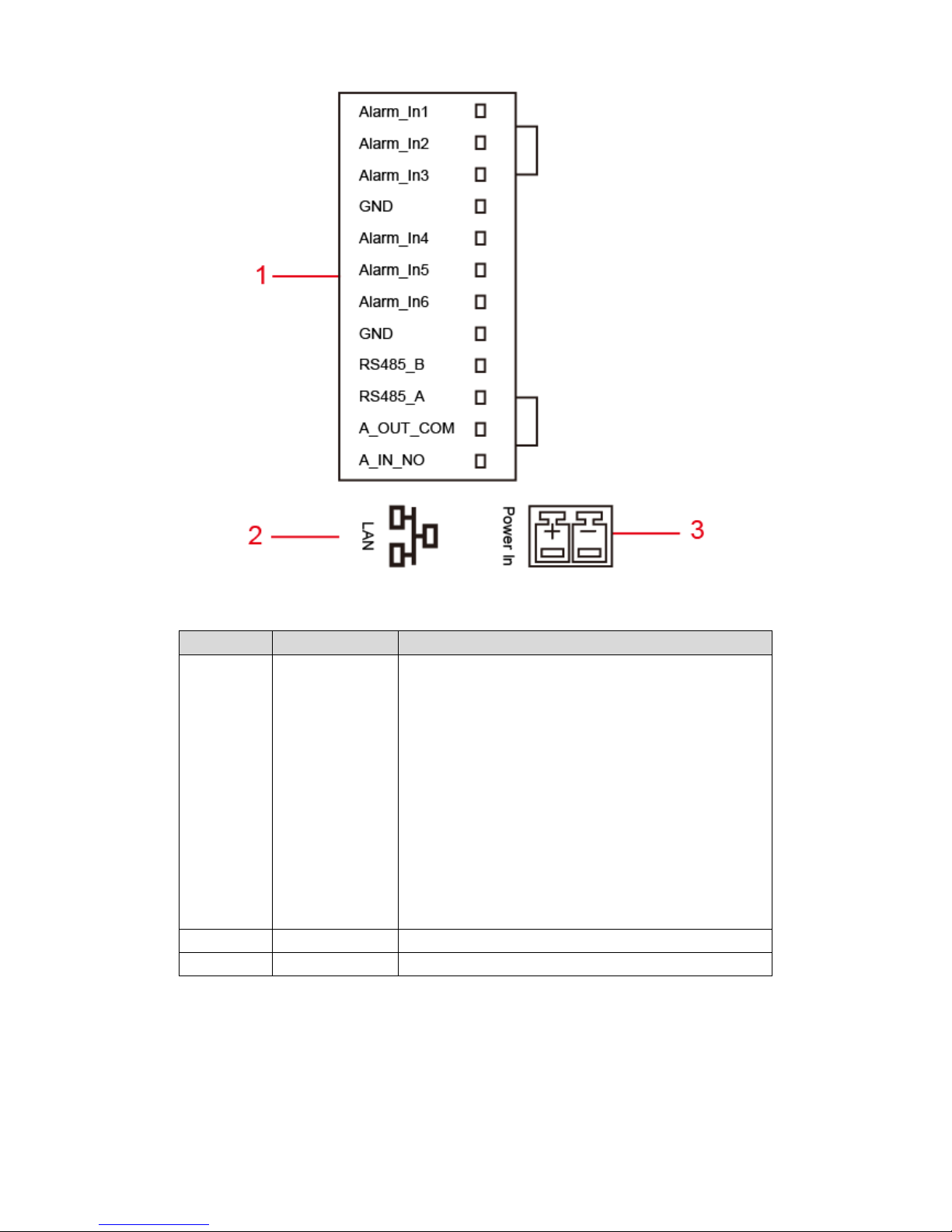
Figure 1-2
No.
Port
Note
1
12-pin Port
Alarm input 1.
Alarm input 2.
Alarm input 3.
GND.
Alarm input 4.
Alarm input 5.
Alarm input 6.
GND.
RS485A port.
RS485B port.
Alarm output port COM(standard N/A).
Alarm output port NO(standard N/A).
2
Network Port
Plug in RJ45 Ethernet cable
3
Power Port
2-pin green 12V power.
Chart 1-2

2 Installation
2.1 Install Device
Warning:
Avoid installation in poor environment, such as condensation, high temperature, oil stain,
dust, corrosion or direct sunlight.
After device is plugged to power, if you find any abnormal phenomenon, you shall
immediately unplug network cable and cut power supply. You may re-plug in power after
troubleshooting.
Project installation and debugging must be done by professionals. Please do not open the
device in case of failure, and please contact after sales service.
This device support direct installation and metal embedded case installation.
See Chart 2-1.
Component Name
Diagram
Quantity
M4×30 cross pan head
screw
3
Chart 2-1
2.1.1 Metal Embedded Case
Step 1. Embed metal case into wall at appropriate height.
Note:
Recommended distance from device center to ground is 1400mm~1600mm.
Step 2. Install installation bracket on metal case, fixed with screw.
Step 3. Fix the device unit on installation bracket, fixed with buckle.
See Figure 2-1.
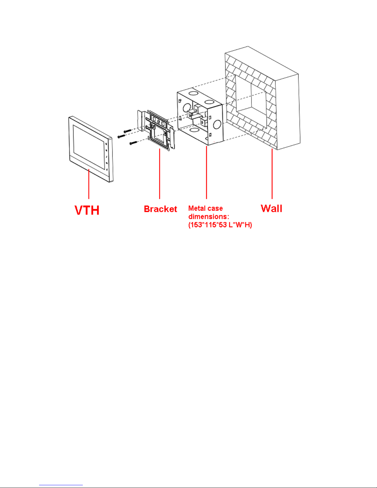
Figure 2-1
2.1.2 Direct Installation
Direct installation is to pull all wiring from side of device without digging holes on wall for wiring.
Step 1. Fix installation bracket on wall with screw.
Step 2. Fix device on installation bracket and buckle it. See Figure 2-2.
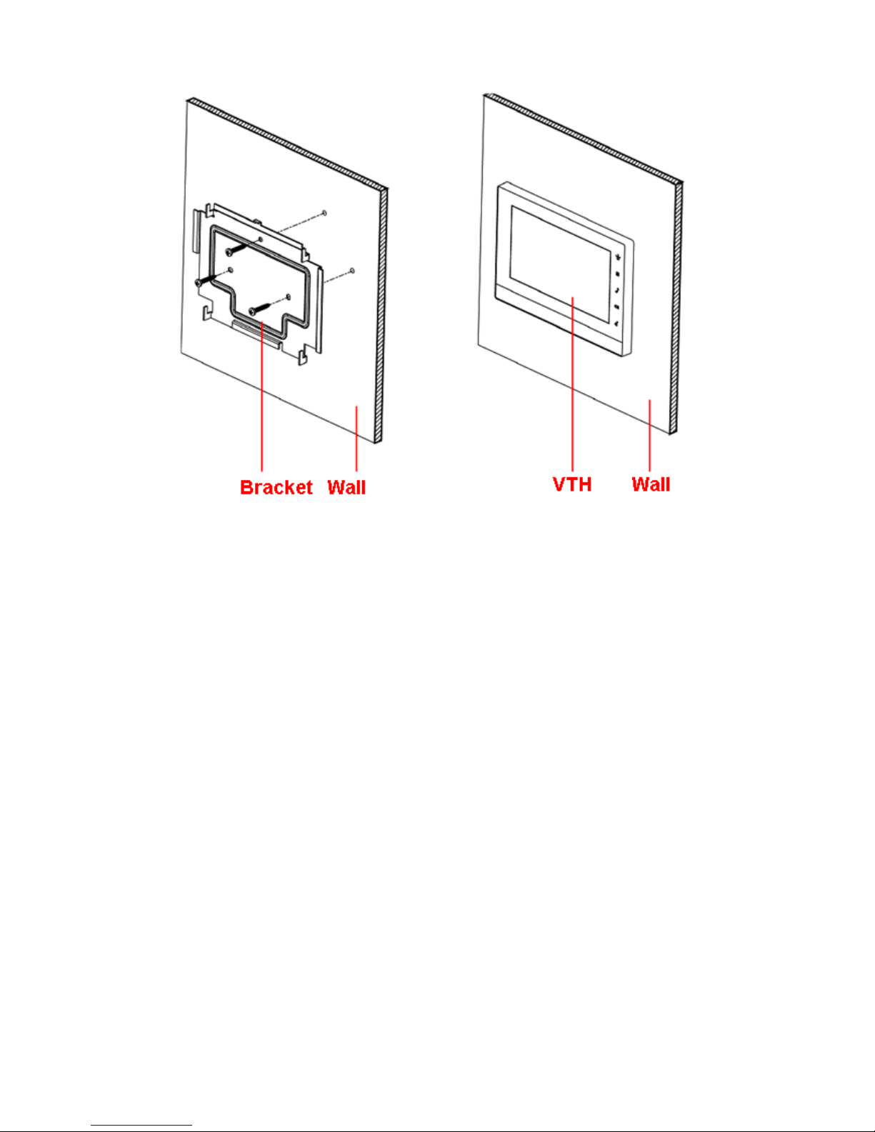
Figure 2-2
2.2 Cable Connection
Please see Ch 1.2.
3 Basic Config
Quickly configure VTH and VTO to fulfill real-time talk, monitor and etc.
Note:
In Project Setup page (for engineer only), password to enter is 888888.
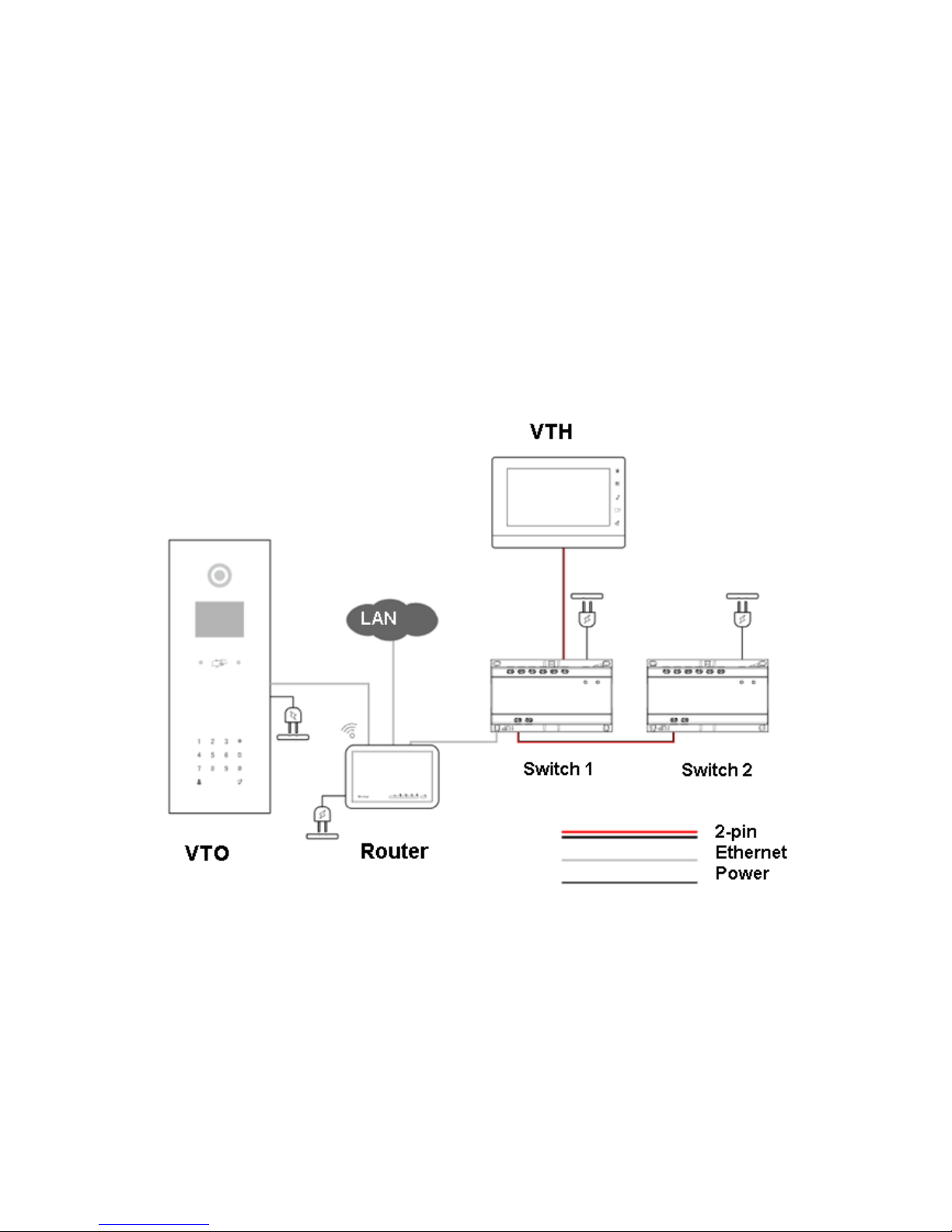
3.1 Networking
See Figure 3-1.
Figure 3-1
3.2 Device Config
Step 1. In Project Settings interface, select System Settings>Project Settings.
Step 2. Enter password (888888 by default) to enter Project Settings interface. See Figure
3-2.
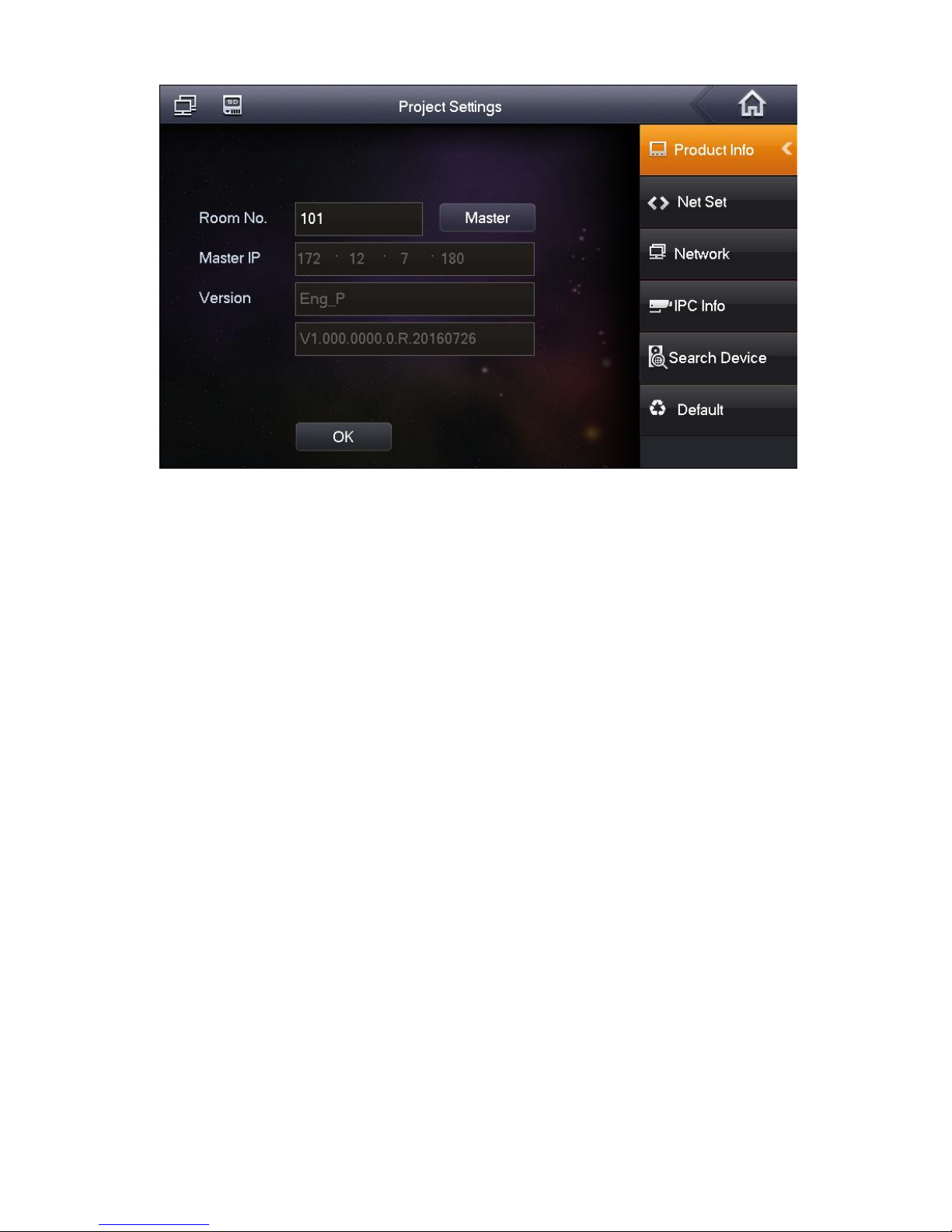
Figure 3-2
Step 3. Set VTH room no.
Warning:
VTH room no. must match VTH shirt no. of corresponding VTO WEB.
If this VTH is master VTH.
1. Fill in room no.
2. Click OK to save.
If this VTH is extension, click Master, select Extension.
1. Fill in room no., and master IP.
See Figure 3-3.
Note:
Part of VTH extension config will be synced with master VTH, which cannot be modified.

Figure 3-3
2. Click OK to save.
Step 4. Set VTH network.
Click Network, system shows Network interface.
Select static IP, manually enter device IP, subnet mask, gateway and etc.
Select DHCP, auto get device IP, subnet mask, gateway and etc.
Note:
Telnet server is ON, debugging personnel can login via telnet+IP to view VTH config.
Step 5. Add VTO info.
1. By Terminal.
System shows network terminal interface.
2. Fill in VTO name, VTO IP address, and set Enable Status to ON, see Figure 3-4.
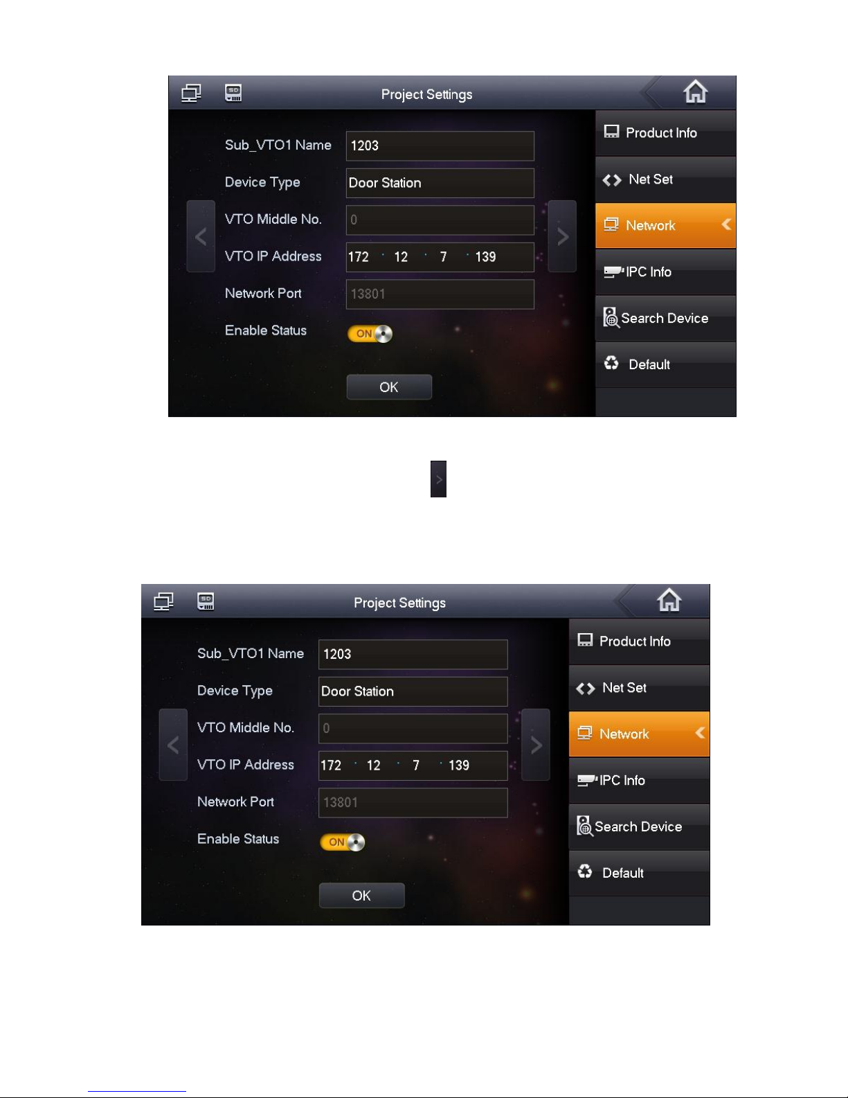
Figure 3-4
If you want to add extension VTO, you can click to page down. Fill in extension VTO name,
extension VTO IP address. Set enable status to ON. You can add more than one extension
VTO. See Figure 3-5.
Note:
You can add more than one VTO if you need.
Figure 3-5
Step 6. Click OK.
3.3 Config Complete
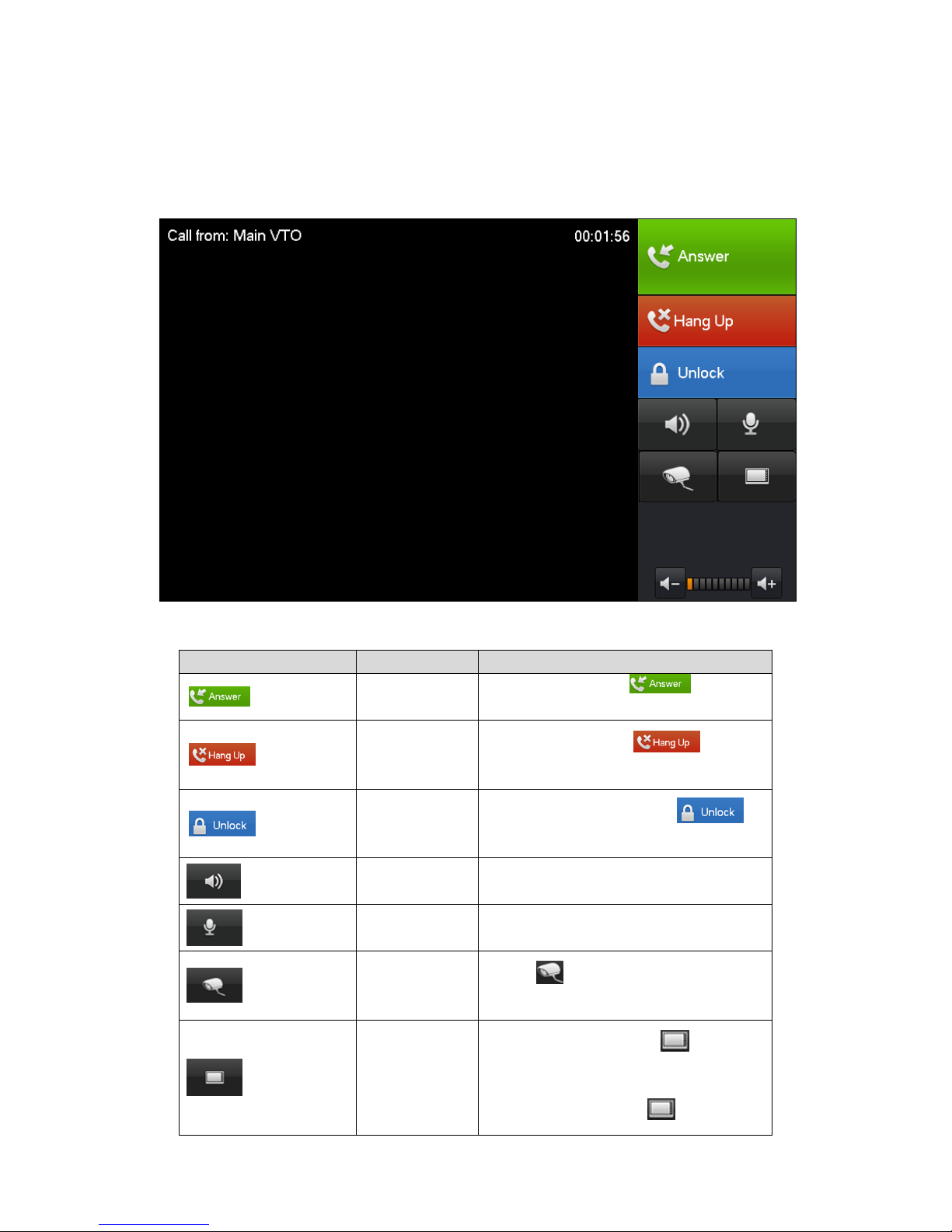
After config is complete, main VTO call VTH. VTH pops up monitor video and operation
buttons. See Figure 3-6.
Figure 3-6
Icon
Name
Note
Accept`
Incoming call, click to accept
call.
Hang up
Incoming call, click to hang
up.
Unlock
VTH in calling status, click to
unlock corresponding VTO
Speaker
Used to enable or disable VTH audio
output.
MIC
Used to enable or disable VTH audio
input.
Monitor IPC
Click to select IPC you want to
monitor.
Switch
Monitor VTH, click to switch
to monitor IPC.
Monitor IPC, click to switch to
 Loading...