

Dahua VTH5221DW-C, VTH5221DW, VTH5221D, VTH5221D-C User Manual

7-inch Digital VTH User’s Manual
V1.0.0

Table of Contents
1 General Introduction ................................................................................................. 5
1.1 Product Intro ............................................................................................................. 5
1.2 Applicable Model ....................................................................................................... 5
2 Structure and Appearance ........................................................................................ 6
2.1 Front Panel ............................................................................................................... 6
2.2 Rear Panel ................................................................................................................ 7
3 Networking ................................................................................................................ 9
4 Installation and Debug ............................................................................................ 10
4.1 Device Wiring .......................................................................................................... 10
4.2 Device Installation ................................................................................................... 10
4.2.1 Screw ................................................................................................................... 11
4.2.2 Steps .................................................................................................................... 11
4.3 Device Debug ......................................................................................................... 12
4.3.1 Before Debugging ................................................................................................. 12
4.3.2 Debug Device ....................................................................................................... 12
4.3.3 Successfully Debug .............................................................................................. 15
5 Product Function ..................................................................................................... 18
5.1 Homepage .............................................................................................................. 18
5.2 Setting .................................................................................................................... 19
5.2.1 Ring ...................................................................................................................... 19
5.2.2 DND ..................................................................................................................... 20
5.2.3 Alarm .................................................................................................................... 22
5.2.4 Mode ................................................................ .................................................... 23
5.2.5 General ................................................................................................................ 24
5.2.6 Production ............................................................................................................ 26
5.3 Call ......................................................................................................................... 26
5.3.1 Call Resident ........................................................................................................ 26
5.3.2 Contact ................................................................................................................. 28
5.3.3 Recent Call ........................................................................................................... 29
5.4 SOS Call ................................ ................................................................................. 30

5.5 Monitor .................................................................................................................... 30
5.5.1 Door ..................................................................................................................... 30
5.5.2 IPC ....................................................................................................................... 32
5.5.3 Favorite ................................................................................................................ 35
5.6 Arm/Disarm ............................................................................................................. 35
5.7 Info.......................................................................................................................... 37
5.8 Default .................................................................................................................... 38
Appendix 1 Technical Specification ............................................................................... 39

Important Safeguards and Warnings
Please read the following safeguards and warnings carefully before using the product in order
to avoid damages and losses.
Note:
Do not expose the device to lampblack, steam or dust. Otherwise it may cause fire or
electric shock.
Do not install the device at position exposed to sunlight or in high temperature.
Temperature rise in device may cause fire.
Do not expose the device to humid environment. Otherwise it may cause fire.
The device must be installed on solid and flat surface in order to guarantee safety
under load and earthquake. Otherwise, it may cause device to fall off or turnover.
Do not place the device on carpet or quilt.
Do not block air vent of the device or ventilation around the device. Otherwise,
temperature in device will rise and may cause fire.
Do not place any object on the device.
Do not disassemble the device without professional instruction.
Warning:
Please use battery properly to avoid fire, explosion and other dangers.
Please replace used battery with battery of the same type.
Do not use power line other than the one specified. Please use it properly. Otherwise,
it may cause fire or electric shock.
Special Announcement
This manual is for reference only.
All the designs and software here are subject to change without prior written notice.
owners.
If there is any uncertainty or controversy, please refer to the final explanation of us.

1 General Introduction
1.1 Product Intro
7 inch digital VTH requires simple operation and easy installation, support:
WI-FI connection.
Call, video talk, remote unlock with VTO.
Message with video for call from VTO
VTH monitors VTO or any other specific camera.
One-click call management center (MGT center).
Link alarm control.
Search of all call records.
1.2 Applicable Model
This user’s manual is applicable to many models of product, please refer to Chart 1-1.
Model
Color
Front
Camera
Screen
SD Card
VTH5221DW
Silver+White
Not support
Capacitive
touch screen
Support
VTH5221D
Gold+Black
Not support
Capacitive
touch screen
Support
VTH5221DW-C
Silver+White
Support
Capacitive
touch screen
Support
VTH5221D-C
Gold+Black
Support
Capacitive
touch screen
Support
Chart 1-1
2 Structure and Appearance
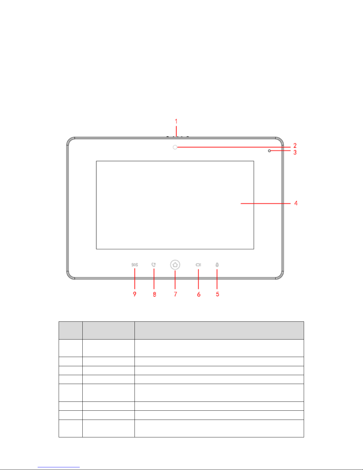
2.1 Front Panel
Note:
Only VTH5221D(W)-C has front camera and other models do not support front camera.
Front panel is in Figure 2-1. Components are defined in Chart 2-1.
Figure 2-1
No.
Component
Name
Description
1
Camera Cover
Switch
Slide, you can cover or open camera.
2
Camera
-
3
MIC
- 4 Screen
-
5
Unlock
During incoming call, call, and monitoring, press this button to
unlock corresponding door.
6
Monitor
Monitor VTO video.
7
Homepage
Press this button to return to homepage.
8
Call
In call status, press this button to accept call; during call, press
this button to hang up.
No.
Component
Name
Description
9
Emergency
In emergency, press this button to call MGT center.
Chart 2-1
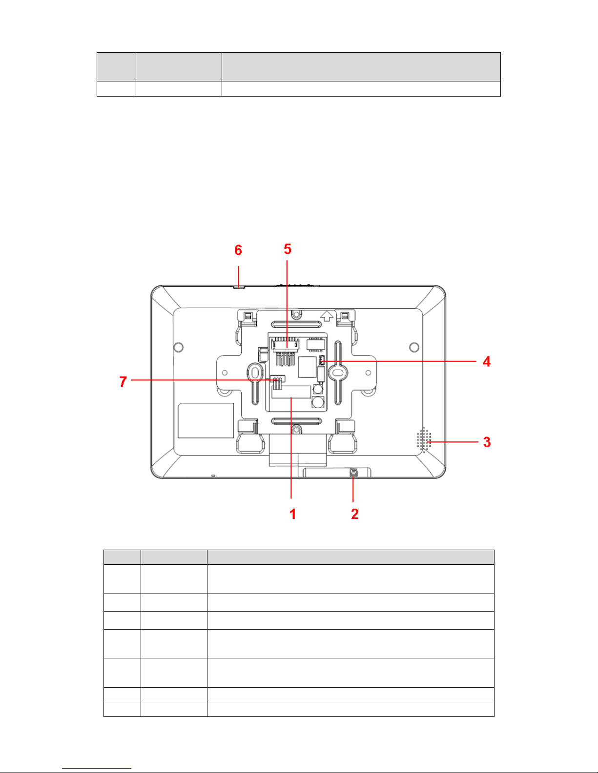
2.2 Rear Panel
Different models have different real panels, but all of interfaces are the same.
Real panel is in Figure 2-2. Components are in
Figure 2-2
No.
Name
Description
1
Alarm
Interface
6-ch alarm and 1-ch alarm output
2
SD Card Slot
Insert SD card.
3
Loudspeaker
-
4
Debug
Interface
Debug serial.
5
Ethernet
Port
Plug in Ethernet cable.
6
Reset
Press Reset button, to reboot system.
7
RS485
485 expansion interface.

No.
Name
Description
Interface
Chart 2-2
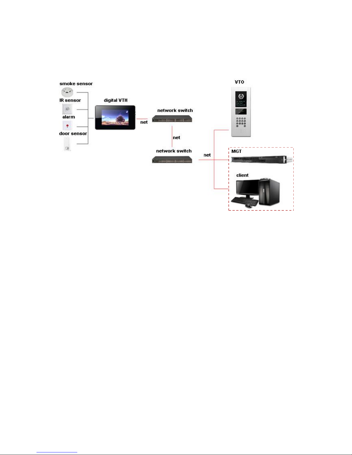
3 Networking
VTH networking is in Figure 3-1.
Figure 3-1
4 Installation and Debug
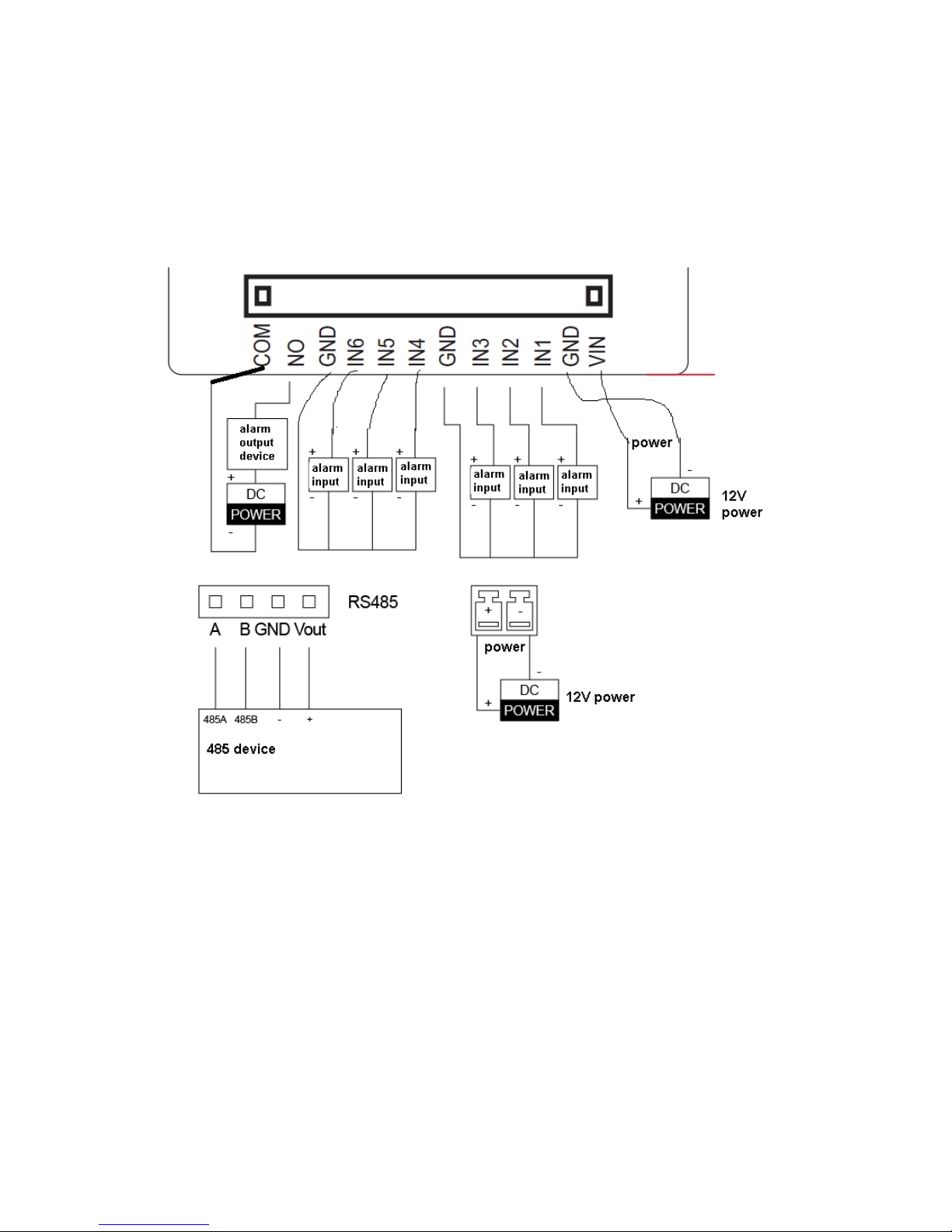
4.1 Device Wiring
Device wiring is in Figure 4-1.
Figure 4-1
4.2 Device Installation
Warning:
Avoid installation in poor environment, such as condensation, high temperature, oil stain,
dust, corrosion or direct sunlight.
Project installation and debugging must be done by professionals. Please do not open the
device in case of failure, and please contact after sales service.
4.2.1 Screw
Component Name
Diagram
Quantity
M4×30 cross pan head
machine screw
2
Chart 4-1
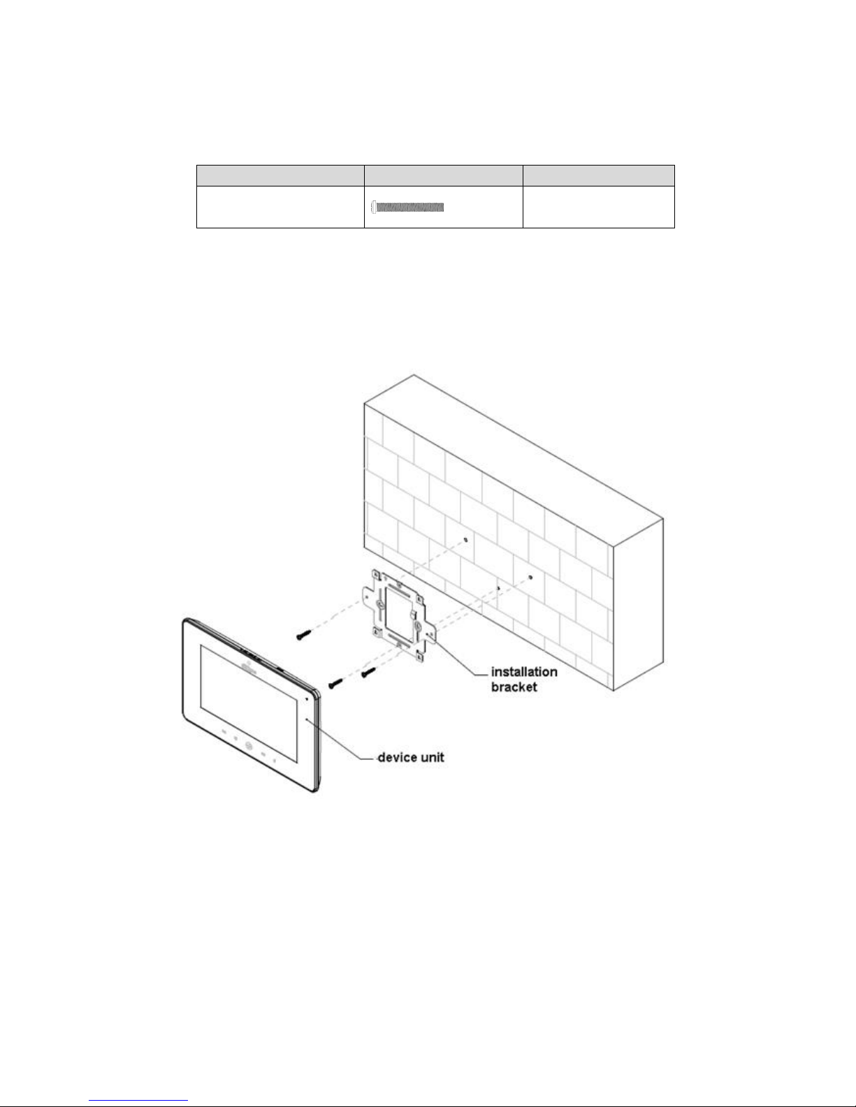
4.2.2 Steps
See Figure 4-2.
Figure 4-2
Step 1. Embed 86 box into wall.
Step 2. Fix installation bracket on 86 box with two M4×30 cross pan head machine screws.
Step 3. Fix device unit on installation unit with buckle.
Note:
During installation, the recommended distance from device center to ground is
1.4m~1.6m.
4.3 Device Debug
4.3.1 Before Debugging
Debugging personnel shall be familiar with related materials, know device installation, wiring
and usage.
Debugging personnel check whether circuit has short circuit or open circuit or not. Make sure
circuit is normal, plug device to power.
After debugging end, clear up site (handle plugs, fix device and etc.)
4.3.2 Debug Device
Step 1. Plug device to power.
Step 2. In homepage, long press Settings for 6 seconds. Device pops up Password
Verification box.
Step 3. Enter project setup password which is 888888 by default.
Step 4. Press Net Set to connect VTH.
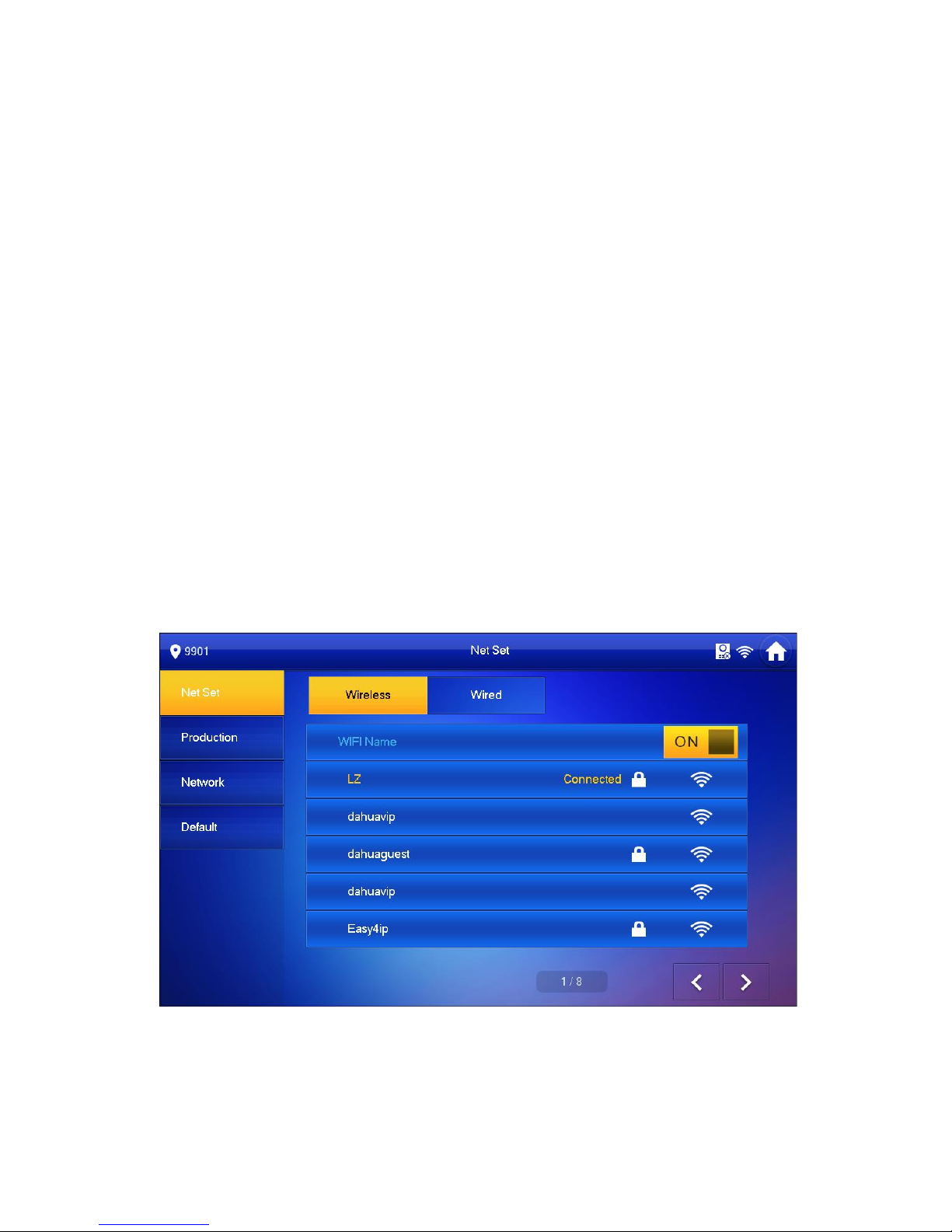
Wireless:
If the VTH supports WI-FI, you can select wireless connection.
1. Select Wireless, open WLAN, view available WI-FI. See Figure 4-3.
Figure 4-3
2. Select WI-FI you want to connect, and in pop-up WLAN connection window,
enter WI-FI password.
3. Press OK.
 Loading...