

Dahua VTH1550CHW-2 User Manual

2-Wire VTH1550CHW-2 User’s Manual
V1.0.0

Table of Contents
1 General Introduction ........................................................................................................... 4
1.1 Network .............................................................................................................................. 4
1.2 Front Panel .......................................................................................................................... 5
1.3 Rear Panel ........................................................................................................................... 6
2 Installation .......................................................................................................................... 7
2.1 Install Device ....................................................................................................................... 7
2.1.1 Screw ................................................................................................................................ 7
2.1.2 Steps ................................................................................................................................. 7
2.2 Cable Connection................................................................................................................. 8
2.3 Basic Config ......................................................................................................................... 8
2.3.1 Config ............................................................................................................................... 8
2.3.2 Result Verification ........................................................................................................... 11
3 Product Function ............................................................................................................... 12
3.1 Basic Function ................................................................................................................... 12
3.1.1 Main Menu ..................................................................................................................... 12
3.1.2 Video Talk ....................................................................................................................... 13
3.1.3 Security ........................................................................................................................... 14
3.1.4 Info Search ...................................................................................................................... 16
3.1.5 System Settings ............................................................................................................... 17
3.2 Unlock ............................................................................................................................... 21
3.3 Arm/Disarm ....................................................................................................................... 21
3.4 2.4 Screen Calibration ........................................................................................................ 22
Appendix 1 Technical Specification ........................................................................................... 23
Appendix 2 Toxic or Hazardous Materials or Elements .............................................................. 24

Important Safeguards and Warnings
Please read the following safeguards and warnings carefully before using the product in order
to avoid damages and losses.
Note:
Do not expose the device to lampblack, steam or dust. Otherwise it may cause fire or
electric shock.
Do not install the device at position exposed to sunlight or in high temperature.
Temperature rise in device may cause fire.
Do not expose the device to humid environment. Otherwise it may cause fire.
The device must be installed on solid and flat surface in order to guarantee safety
under load and earthquake. Otherwise, it may cause device to fall off or turnover.
Do not place the device on carpet or quilt.
Do not block air vent of the device or ventilation around the device. Otherwise,
temperature in device will rise and may cause fire.
Do not place any object on the device.
Do not disassemble the device without professional instruction.
Warning:
Please use battery properly to avoid fire, explosion and other dangers.
Please replace used battery with battery of the same type.
Do not use power line other than the one specified. Please use it properly. Otherwise,
it may cause fire or electric shock.
Special Announcement
This manual is for reference only.
All the designs and software here are subject to change without prior written notice.
owners.
If there is any uncertainty or controversy, please refer to the final explanation of us.
1 General Introduction
1.1 Network
Here introduces application of VTH, and please read the following contents before installation.
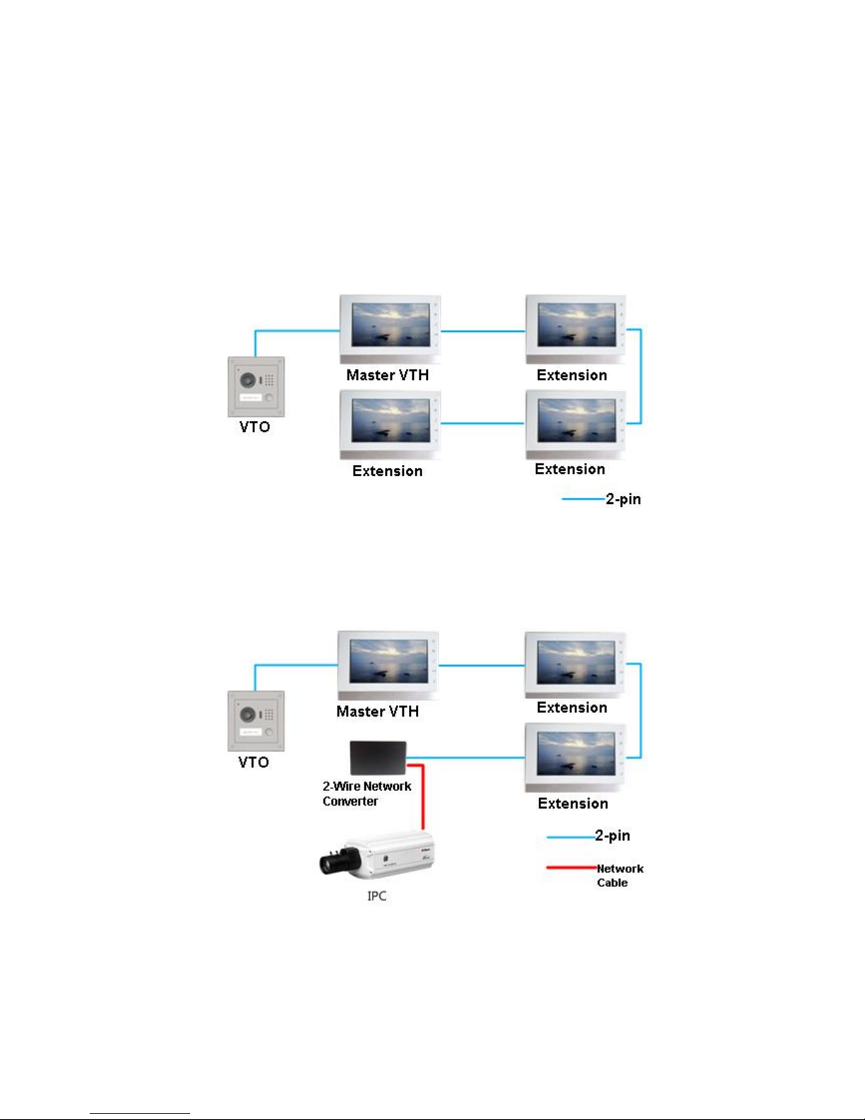
See Figure 1- 1 Villa Networking 1 and Figure 1- 2 Villa Networking 2.
Figure 1- 1 Villa Networking 1
1 VTO and 4 VTH (maximum) are connected via 2-pin cable for networking. When visitor calls
the resident via VTO, resident may unlock door from any one master VTH or extension.
Figure 1- 2 Villa Networking 2
1 VTO, 3 VTH (maximum), analog converter are connected via 2-pin cable. On analog
converter, use network cable to connect IPC for networking. When visitor calls the resident via
VTO, resident may unlock door from any one master VTH or extension. Resident can view IPC
video on VTH.
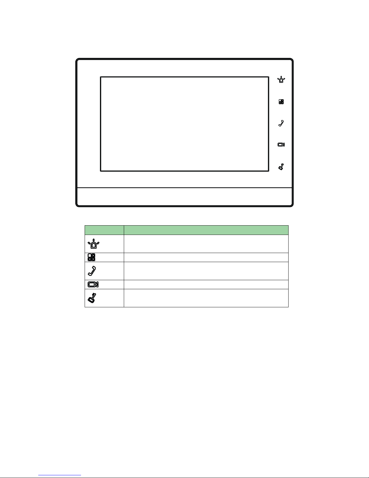
1.2 Front Panel
Figure 1- 3
Name
Note
Emergent call to center.
Press this button to return to main menu.
Under calling, status, press this button to answer call. During
a call, press this button to hang up.
Monitor VTO video.
During incoming call, calling, monitoring status, press this
button to unlock.
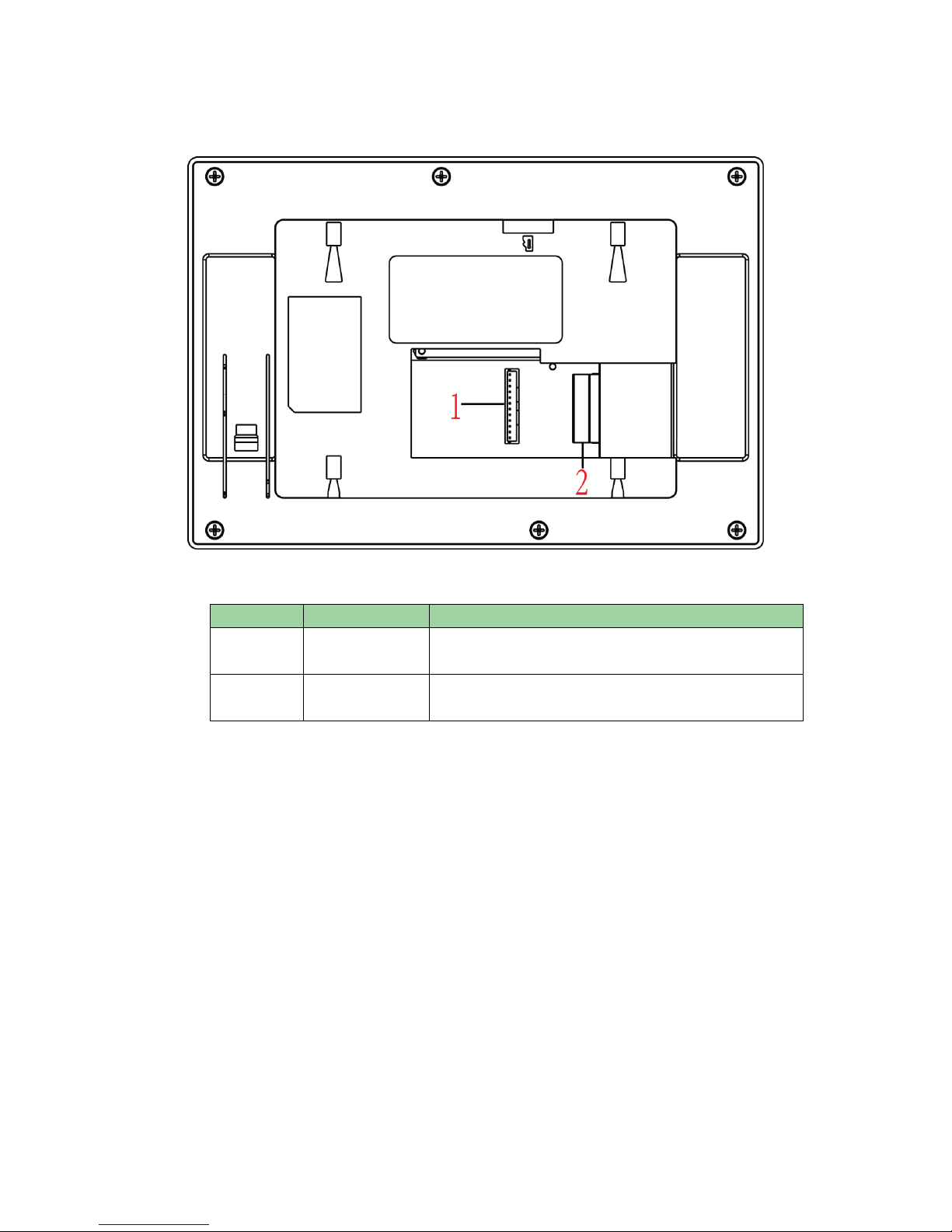
1.3 Rear Panel
Figure 1- 4
No.
Name
Note
1
Alarm port
6-ch alarm in and 1-ch alarm out, refer to label for
details.
2
2-Wire port
3 groups of 2-wire ports, may connect to power,
VTH, VTO or converter module.

2 Installation
2.1 Install Device
This device support direct installation, as not digging exit hole of wiring on wall and all wirings
come out from side.
Warning:
Avoid installation in poor environment, such as condensation, high temperature, oil stain,
dust, corrosion or direct sunlight.
After device is plugged to power, if you find any abnormal phenomenon, you shall
immediately unplug network cable and cut power supply. You may re-plug in power after
troubleshooting.
Project installation and debugging must be done by professionals. Please do not open the
device in case of failure, and please contact after sales service.
2.1.1 Screw
Component Name
Diagram
Quantity
ST3x18 cross pan head
tail self-tapping screwnickel plating white
3
Chart 2- 1
2.1.2 Steps
Step 1. Fix installation bracket on wall, with screw (STS x 18 cross pan head tail self-tapping
screw).
Step 2. Fix device on installation bracket and buckle it. See Figure 2- 1.

Figure 2- 1
2.2 Cable Connection
Please see Ch 1.3.
2.3 Basic Config
After config, it will have talk function.
2.3.1 Config
Step 1. In Project Settings interface, select System Settings>Project Settings and enter
password (002236) to enter Project Settings interface. See Figure 2- 2.
 Loading...