

Page 1

7” Analog VTH User’s Manual
V.1.2.0
Page 2

Important Safeguards and Warnings
Please read the following safeguards and warnings carefully before using the product in order
to avoid damages and losses.
Note:
Do not expose the device to lampblack, steam or dust. Otherwise it may cause fire or
electric shock.
Do not install the device at position exposed to sunlight or in high temperature.
Temperature rise in device may cause fire.
Do not expose the device to humid environment. Otherwise it may cause fire.
The device must be installed on solid and flat surface in order to guarantee safety
under load and earthquake. Otherwise, it may cause device to fall off or turnover.
Do not place the device on carpet or quilt.
Do not block air vent of the device or ventilation around the device. Otherwise,
temperature in device will rise and may cause fire.
Do not place any object on the device.
Do not disassemble the device without professional instruction.
Warning:
Please use battery properly to avoid fire, explosion and other dangers.
Please replace used battery with battery of the same type.
Do not use power line other than the one specified. Please use it properly. Otherwise,
it may cause fire or electric shock.
Special Announcement
This manual is for reference only.
All the designs and software here are subject to change without prior written notice.
All trademarks and registered trademarks are the properties of their respective
owners.
If there is any uncertainty or controversy, please refer to the final explanation of us.
Page 3

Table of Contents
Chapter 1 General Introduction .................................................................................. 4
1.1 Product Appearance ........................................................................................... 4
1.2 Buttons ................................................................................................................ 5
1.3 Indicator ............................................................................................................... 6
1.4 Port ...................................................................................................................... 7
Chapter 2 Installation ................................................................................................. 9
Chapter 3 Basic Function Introduction ..................................................................... 11
3.1 Main Menu ......................................................................................................... 11
3.2 Bidirectional Talk with Management Center ....................................................... 12
3.3 Visual Bidirectional Talk with Door Station ......................................................... 12
3.4 Monitoring Function ........................................................................................... 12
3.5 Unlocking Function ............................................................................................ 12
3.6 DND Function .................................................................................................... 12
3.7 Viewing Announcement ..................................................................................... 13
3.8 Alarm Function .................................................................................................. 13
3.8.1 Arming/Disarming Function ............................................................................. 13
3.8.2 Alarm Message and Reporting Function ......................................................... 13
3.8.3 Alarm Output .................................................................................................. 14
Chapter 4 FAQ ........................................................................................................ 15
Appendix 1 Technical Specifications ........................................................................ 16
Appendix 2 Toxic or Hazardous Materials or Elements ............................................ 17
Page 4
Chapter 1 General Introduction
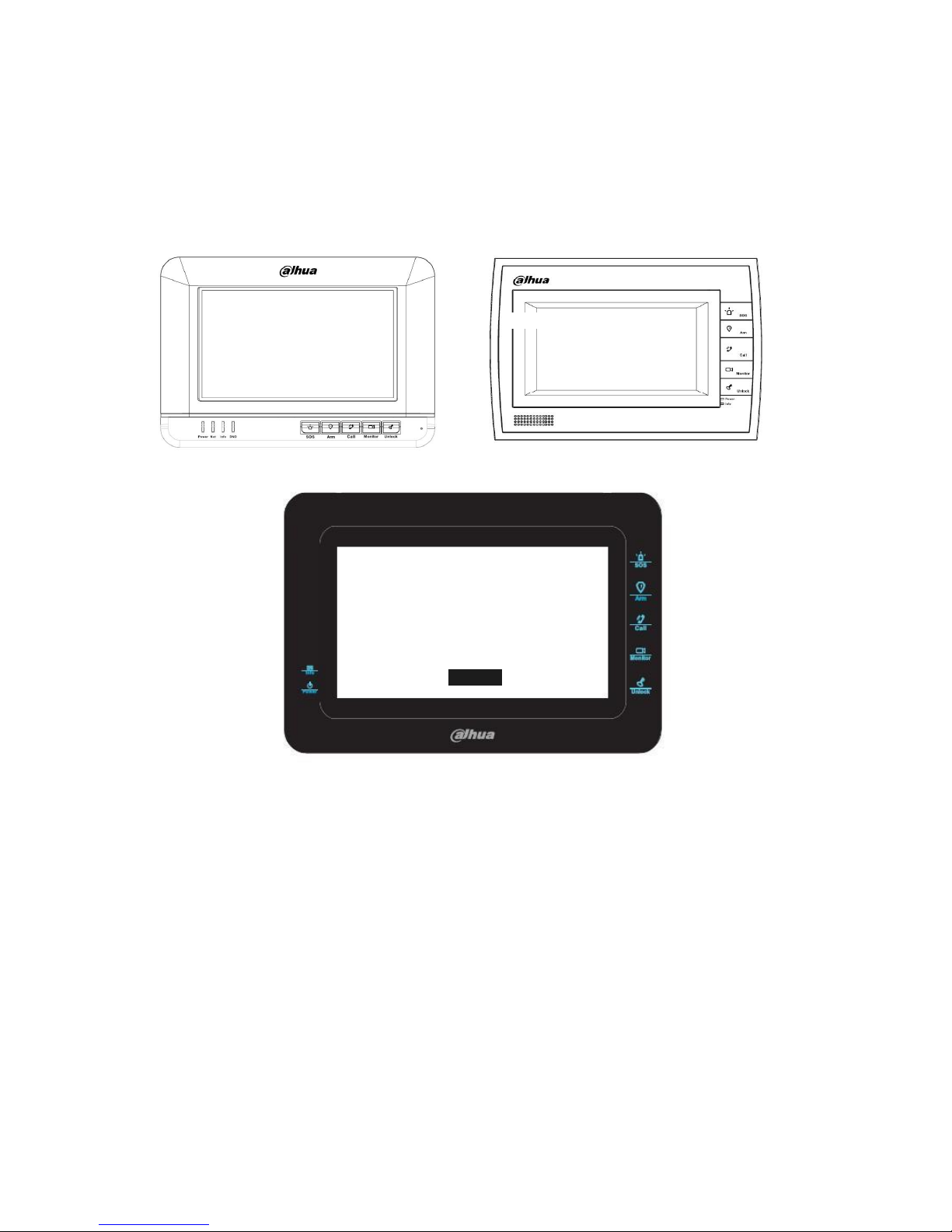
1.1 Product Appearance
The product is classified into the following models. Please see Figure 1-1, Figure 1-2,
Figure 1-3, Figure 1-4 and Figure 1-5.
Figure 1- 1 VTH150xA Figure 1- 2 VTH150xAH
Figure 1- 3 VTH150xB
Page 5
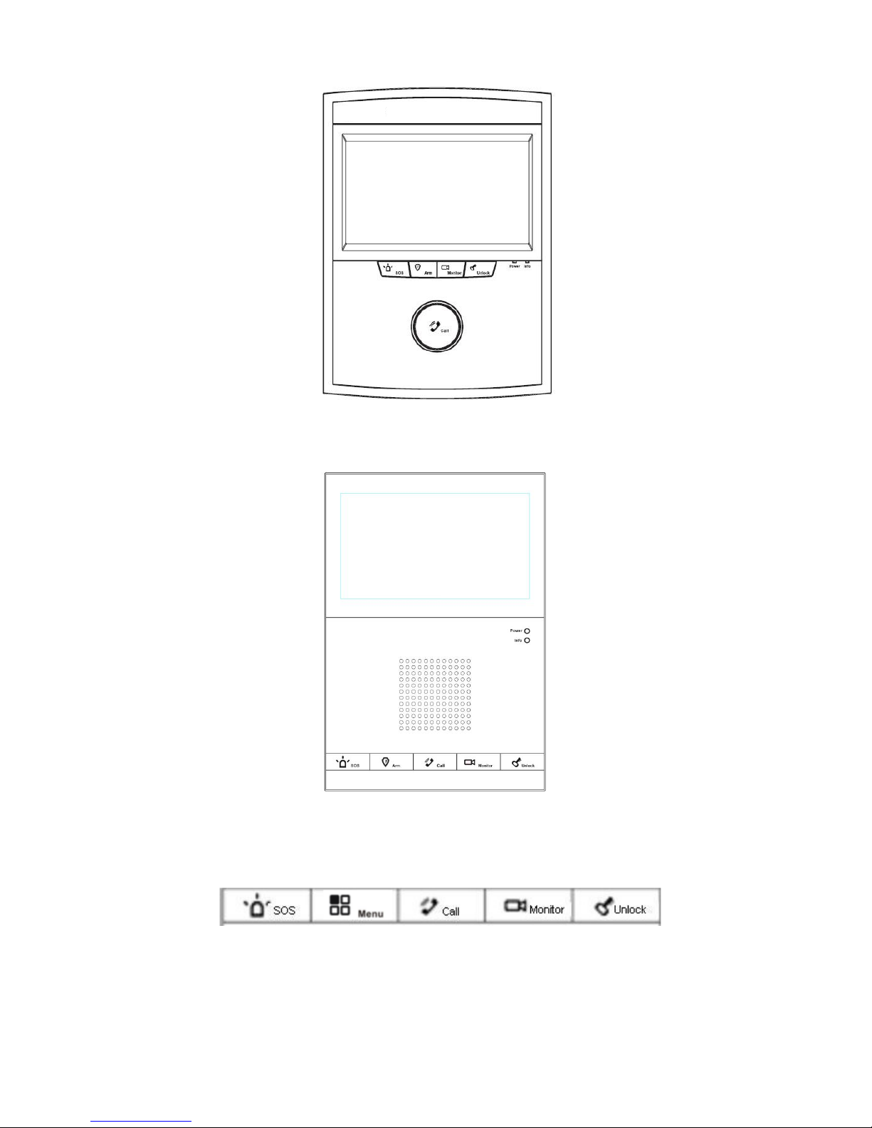
Figure 1- 4 VTH150xAS
Figure 1- 5 VTH150xCS
1.2 Buttons
Figure 1- 6
The buttons are illustrated in Figure 1- 6. Their descriptions are shown in Chart 1- 1.
For different 7”analog VTHs, their button locations may vary, but the function of buttons
with same label is identical.
Page 6
No.
Name
Description
1
SOS
Under any interface, press this button can call management center. If you
are in menu, press SOS to return to previous menu.
2
Menu or Arm
Press the button to enter menu and continue pressing this button to go to
next menu. Under standby, you can long press for 2s for menu or 5s to
disarm
3
Call
Press the button when being called, you can answer call; press the button
during a call, you can hang it up.
Under standby status, long press call button for 5s, you can turn on or turn
off DND (if it is already on).
4
Monitor
Monitor door station video. Under standby status, you may press this
button to view announcement if available, and you may press this button to
view alarm info if available.
5
Unlock
Press this button during incoming call, calling, and monitoring, you can
unlock corresponding door station.
Chart 1- 1
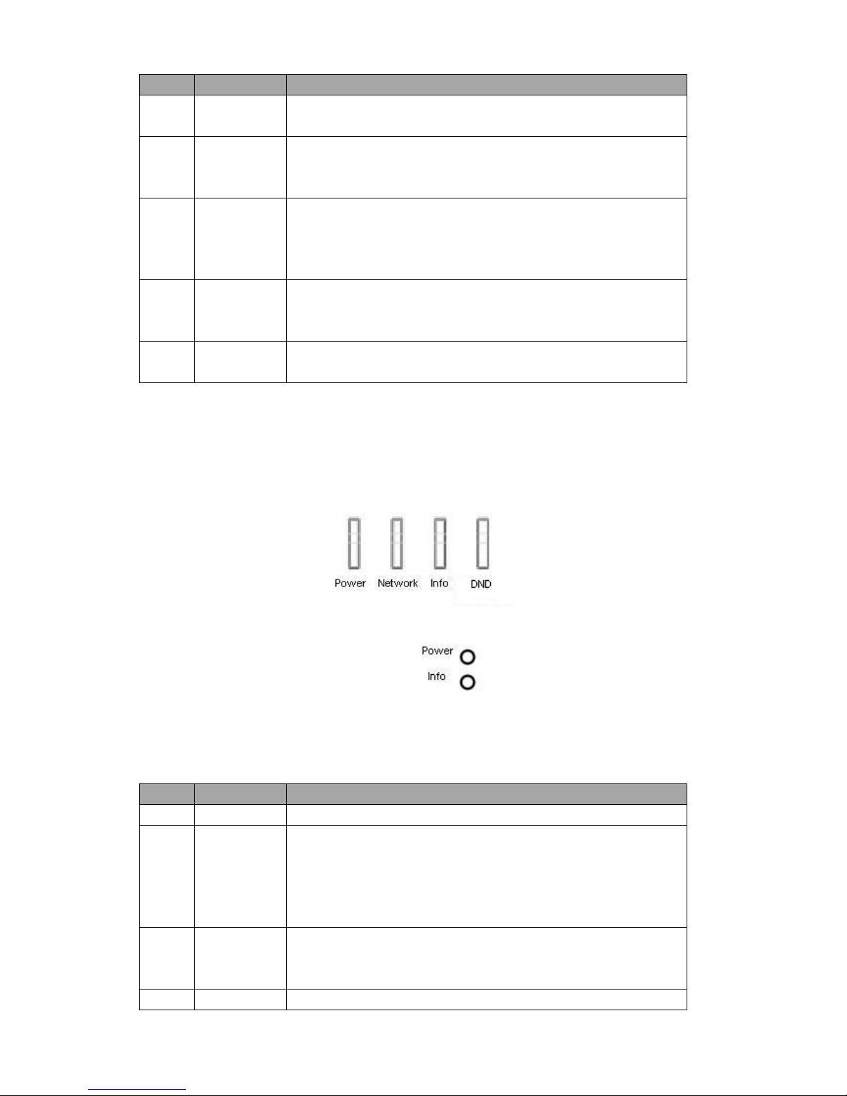
1.3 Indicator
The indicators are illustrated in Figure 1- 7 and Figure 1-8.
Figure 1- 7 VTH150xA
Figure 1- 8 VTH150xCS
Some 7 ” analog VTH only have power and info indicators, and their shapes vary among
different models. Please see Chart 1- 2.
No.
Name
Description
6
Power
Power works as usual, light on;
7
Info
When there is no announcement or alarm info, light turns on if
arm; light turns off if disarm;
When there is announcement but no alarm info, light flashes
slowly.
When there is alarm info, light flashes intensely.
8
Network
When communication with door station is normal, light turns on;
if there is abnormality, light turns off. Only VTH1500A has
network indicator.
9
DND(Do not
When DND is on, light remains on; when DND is off, light
Page 7

disturb)
remains off. Only VTH1500A has DND indicator.
Chart 1- 2
1.4 Port
For different 7”analog VTHs, their port locations may vary, but the function of ports with
same label is identical. Please subject to actual product.
The device interface is shown as follows, please see Figure 1- 9 and Figure 1- 10.
Figure 1- 9
Please see Chart 1- 3.
Page 8

No.
Name
Description
1
Alarm Interface
8-ch alarm, 2-ch GND.
2
Communication Port
Power, control signal and A/V differential signal
included.
3
Earphone Interface
Only models with earphone have this interface.
Chart 1- 3
Figure 1- 10
No.
Name
Description
Note
1
Alarm input
port
6-ch alarm input
N/A
2
Alarm output
port
1-ch alarm output
N/A
3
COM
Power, control signal and A/V
differential signal included.
Convertor is provided by
default.
This VTH supports two
methods of power supply,
which may via COM port or
power port. Select either
one.
If supply via power port, and
dial switch 1 and 2 are at
ON, VTH can supply power
to VTO.
4
Power port
Power to VTH.
5
Dial switch
Control if supply power to villa
VTO.
Chart 1- 4
Page 9

Chapter 2 Installation
Here makes VTH1500AH as an example.
Step 1. Fix installation bracket on wall with four screws (ST3 x 18).
Step 2. Fix device onto bracket, with bucket. See Figure 2- 1.
Figure 2- 1
Note:
Device center to ground shall be 1400mm to 1600mm.
Try to avoid exposing VTH to bad environment, such as condensation, high temperature,
greasy dirt, dust, corrosion, direct sunlight and etc.
If there is abnormality after you plug in network cable, you should unplug it immediately
and unplug the device from power supply. You may plug in the device to power supply
after troubleshoot.
Device installation and test must be done by professional staff. If there is any malfunction
Page 10

or failure, please do not try to dismount or fix it by yourself, and please contact after-sales
department for assistance.
Page 11

Chapter 3 Basic Function Introduction
3.1 Main Menu
Under standby interface, press menu button to enter main menu.
Item
Function
Operation
MIC
Adjust local MIC
volume
1. In main menu, press menu
button, select MIC.
2. Press monitor or unlock button, decrease
or increase MIC volume.
Call
Adjust local call
volume
1. In main menu, press menu
button, select call.
2. Press monitor or unlock button,
decrease or increase call volume.
Ring
Adjust incoming call
ring volume, or return
call ring of
management center.
1. In main menu, press menu
button, select ring.
2. Press monitor or unlock button,
decrease or increase ring volume.
Brightness
Adjust local screen
brightness
1. In main menu, press menu
button, select brightness.
2. Press monitor or unlock button,
decrease or increase brightness.
Contrast
Adjust local screen
contrast
1. In main menu, press menu
button, select contrast.
2. Press monitor or unlock button,
decrease or increase contrast.
Setting
Set arm strategy.
1. Please see Ch 3.8.1.1.
Issue Card
Issue Card
1. In main menu, press menu
button, select issue card option.
2. Select issue card.
3. Place empty card in the card
swiping area on VTO. When card is
successfully issued, it will generate DU
sound.
Note:
Please swipe card within 10 minutes after
menu operation, otherwise the session will
expire.
Do not issue more than 30 cards at the same
time.
Delete All
1. In main menu, press menu
button, select issue card option.
2. Select delete all, to cancel all
Page 12

A&C authorizations.
3.2 Bidirectional Talk with Management Center
Under any interface, by pressing SOS button, you may immediately switch to call
management center, and if the call goes through, you will hear corresponding audio response
of long and slow beeps from VTH; if the call does not go through; you will also hear
corresponding audio response as short and fast beeps from VTH. You may press SOS button
again to end the call, and VTH will return to standby interface.
When supervisor station calls VTH, VTH will ring, and you may answer by pressing call
button. You may end call by pressing call button again, and VTH will return to standby interface.
See Ch 3.1.
3.3 Visual Bidirectional Talk with Door Station
When door station calls VTH, VTH will ring, meanwhile door station video will be displayed
on screen. You may press call button to answer and then you may perform a bidirectional talk
with the door station, while the screen continues displaying video from door station. You may
end call and video by pressing call button again, and the VTH will return to standby interface.
You can set MIC, call, ring, brightness and contrast when talking to VTO. See Ch 3.1.
When there is incoming call on VTH (before answering call), you can press menu button
to set ring. See Ch 3.1.
Note:
When matching with VTO, under monitoring status, press Call button to talk to VTO.
3.4 Monitoring Function
Under standby interface, by pressing monitor button, you may view video from door
station on the screen. You may turn off monitoring by pressing monitor button again, and VTH
will return to standby interface.
You can set MIC, call, ring, brightness and contrast under monitoring interface byu
pressing menu button. See Ch 3.1.
Note:
When matching with VTO, under monitoring status, press Call button to talk to VTO.
3.5 Unlocking Function
When call from door station, call door station or VTH monitors door station, you may
remotely unlock door station by pressing unlock button.
3.6 DND Function
Under standby status, you may turn on DND function by long pressing call button for 5s;
meantime the screen turns on, there will be corresponding message at left middle position.
Under DND, when door station calls, you may use the video function without incoming ring.
You can connect and start to talk by pressing call button.
Note: For program of some versions, under DND status, message will directly
Page 13

inform you that VTH is busy.
The default DND is 8 hours, and after 8 hours, it will be automatically canceled. To
manually turn off DND: under standby status, long press call button for 5s to turn it off.
3.7 Viewing Announcement
When there is no alarm, VTH receives message sent from platform, and the indicator
flashes slowly. By pressing monitor button, you can view announcement which is added in the
video on door station in rolling display. You can exit announcement viewing by pressing
monitor button again.
Note: When there is alarm, you must confirm the alarm before viewing
announcement.
3.8 Alarm Function
3.8.1 Arming/Disarming Function
3.8.1.1 Arming/Disarming Strategy
Step 1. Under standby status, you may enter main menu by pressing menu.
Step 2. Repeat pressing menu button, select to set menu item. Press call button to enter
setup interface.
Step 3. In setup interface, press menu button, to select alarm zone to set. You can press
monitor or unlock button to switch arming type. Press call button again to select alarm
zone (check as selected).
Step 4. Press menu button, select alarm delay. By pressing monitor or unlock button to select
alarm delay length. Max alarm delay is 120s.
3.8.1.2 Arming/Disarming
Default setup is arming status.
Under arming status and standby interface, long press menu button for 5s, device enters
disarming status. Screen turns on. It shows disarming prompt at the left and turns off light (no
announcement or alarm info).
Under disarming status and standby interface, long press menu button for 2s, device
enters arming status. Screen turns on. It shows arming prompt at the left and light is NO (no
announcement or alarm info).
3.8.2 Alarm Message and Reporting Function
VTH has 8 channels for alarm, with first channel fixed for manual alarm, second channel
fixed for gas alarm, third channel fixed for smoke alarm. When VTH is under arming, excluding
first channel, for alarm triggered in any other channel, its corresponding alarm message will be
displayed on screen, meanwhile VTH’s indicator will flash and ring (first channel excluded).
Page 14

You may confirm alarm message by pressing monitor button, and then indicator resumes, ring
stops and alarm message is cleared. All alarm information will be reported to management
center after local display.
3.8.3 Alarm Output
When alarm occurs, alarm output port will generate level fluctuation for one minute.
Page 15

Chapter 4 FAQ
Q:The screen on VTH is black, and the indicator remains off, what should I do?
A: Check the connection of network cable.
Q: I cannot call or monitor via the VTH, what should I do?
A: Check the connection of network cable, and confirm if the corresponding door
station is working as normal.
Q: When there is incoming call from door station, but the ring is not working, what
should I do?
A: Confirm if you have turn on DND function.
Q: I have other problems, what should I do?
A: Please contact technical staff for further assistance.
Page 16

Appendix 1 Technical Specifications
Video
Video
CVBS composite video
Audio
Bidirectional Talk
1-ch audio input from analog signal of microphone
1-ch audio output which drives loudspeaker via amplifier
Display
Screen Dimension
Color 7” TFT LCD
Resolution
800*480
Alarm
Input
Some: 6-ch alarm input, 1-ch alarm output.
Some: 8-ch alarm
Output
Specifications
Power
DC 24V
Consumption
Standby 1W,max 5W
Environment
-10℃~55℃
Page 17

Appendix 2 Toxic or Hazardous Materials
or Elements
Component
Name
Toxic or Hazardous Materials or Elements
Pb
Hg
Cd
Cr VI
PBB
PBDE
Circuit Board
Component
○ ○ ○ ○ ○
○
Device Case
○ ○ ○ ○ ○ ○
Wire and Cable
○ ○ ○ ○ ○ ○
Packing
Components
○ ○ ○ ○ ○
○
Accessories
○ ○ ○ ○ ○
○
O: Indicates that the concentration of the hazardous substance in all homogeneous materials
in the parts is below the relevant threshold of the SJ/T11363-2006 standard.
X: Indicates that the concentration of the hazardous substance of at least one of all
homogeneous materials in the parts is above the relevant threshold of the SJ/T11363-2006
standard. During the environmental-friendly use period (EFUP) period, the toxic or hazardous
substance or elements contained in products will not leak or mutate so that the use of these
(substances or elements) will not result in any severe environmental pollution, any bodily injury
or damage to any assets. The consumer is not authorized to process such kind of
substances or elements, please return to the corresponding local authorities to process
according to your local government statutes.
Page 18

Note:
This manual is for reference only. Slight difference may be found in user
interface.
All the designs and software here are subject to change without prior written
notice.
All trademarks and registered trademarks are the properties of their respective
owners.
If there is any uncertainty or controversy, please refer to the final explanation
of us.
Please visit our website or contact your local service engineer for more
information.
 Loading...