

Page 1

Video Field Surveillance Unit
User’s Manual
For ARC6416C series
V 1.0.0
1
Page 2

Table of Contents
1 PRODUCT OVERVIEW ...................................................................................................... 1
1.1 Intro to Product ........................................................................................................... 1
1.2 Features ....................................................................................................................... 1
1.3 Typical Networking ..................................................................................................... 1
2 PRODUCT STRUCTURE .................................................................................................... 3
2.1 Checklist ...................................................................................................................... 3
2.2 Dimensions ................................................................................................................. 3
2.3 Front Panel .................................................................................................................. 3
2.4 Rear Panel ................................................................................................................... 4
3 INSTALLATION AND WIRING ................................ ........................................................... 6
3.1 Before Installation ...................................................................................................... 6
3.1.1 Select Installation Position ....................................................................................... 6
3.1.2 Common Tool ........................................................................................................... 6
3.1.3 Requirements for Installation ................................................................................... 6
3.2 Install Field Surveillance Unit.................................................................................... 7
3.3 Install Peripherals ....................................................................................................... 7
3.4 Wiring ........................................................................................................................... 7
3.4.1 Main Power Wiring ................................................................................................... 7
3.4.2 Network Port Wring .................................................................................................. 7
3.4.3 SFP Port Wiring ........................................................................................................ 8
3.4.4 DI Port Wiring ........................................................................................................... 9
3.4.5 AI Port Wiring ........................................................................................................... 9
3.4.6 RS 485 Port Wiring................................................................................................... 9
3.4.7 RS232 Port Wiring.................................................................................................. 10
3.4.8 DO Port Wiring ....................................................................................................... 11
3.4.9 Smoke Sensor Wiring ............................................................................................ 11
3.4.10 Siren Port Wiring ................................................................................................ 12
3.4.11 Audio Input Port Wiring ...................................................................................... 12
3.4.12 Audio Output Port Wiring ................................................................................... 13
Page 3

4 BOOT UP AND OPERATION ........................................................................................... 14
4.1 Boot Up ...................................................................................................................... 14
4.2 Login Web ................................................................................................................. 14
4.3 Setup Wizard ............................................................................................................. 15
4.3.1 Format Storage Card (including SD Card) ............................................................. 15
4.3.2 4G Connection Status ............................................................................................ 16
4.3.3 Add Peripheral Protocol ......................................................................................... 17
4.3.4 Add Peripheral ........................................................................................................ 19
4.3.5 Upload Asset Config .............................................................................................. 21
4.3.6 VPN Connection ..................................................................................................... 21
4.3.7 Platform Input ......................................................................................................... 22
4.3.8 Delivery Mode ........................................................................................................ 23
5 ENVIRONMENT CONFIGURATION ................................................................................. 24
5.1 Peripheral .................................................................................................................. 24
5.2 Data Overlay .............................................................................................................. 27
5.3 Threshold Config ...................................................................................................... 28
5.4 Link Config ................................................................................................................ 30
5.5 Receive Alarm ........................................................................................................... 32
5.6 High Frequency Alarm ............................................................................................. 33
5.7 Power Failure ............................................................................................................ 34
5.8 Environment Log ...................................................................................................... 35
5.9 Protocol ..................................................................................................................... 37
5.10 Sampling Parameter ................................................................................................. 38
5.11 Platform Asset Code ................................................................................................ 38
5.12 Asset Config Upload ................................................................................................ 39
5.13 Port Mapping Config ................................................................................................ 40
5.14 Out Mode ................................................................................................................... 42
5.15 Platform Input ........................................................................................................... 42
5.16 Test Page ................................................................................................................... 43
Page 4

5.17 Interactive Page ........................................................................................................ 43
6 SETUP .............................................................................................................................. 45
6.1 Camera ....................................................................................................................... 45
6.1.1 Remote Device ....................................................................................................... 45
6.1.2 Encode ................................................................................................................... 47
6.1.3 Cam Name ............................................................................................................. 51
6.2 Network ...................................................................................................................... 52
6.2.1 TCP/IP .................................................................................................................... 52
6.2.2 Port ......................................................................................................................... 53
6.2.3 WIFI ........................................................................................................................ 55
6.2.4 4G ........................................................................................................................... 56
6.2.5 PPPoE .................................................................................................................... 56
6.2.6 DDNS ..................................................................................................................... 57
6.2.7 IP Filter ................................................................................................................... 58
6.2.8 Email ...................................................................................................................... 59
6.2.9 FTP ......................................................................................................................... 60
6.2.10 SNMP ................................................................................................................. 62
6.2.11 Multicast ............................................................................................................. 63
6.2.12 VPN .................................................................................................................... 64
6.2.13 Alarm Center ...................................................................................................... 66
6.2.14 P2P .................................................................................................................... 67
6.2.15 HTTPS ............................................................................................................... 68
6.3 Event .......................................................................................................................... 73
6.3.1 Video Detect ........................................................................................................... 73
6.3.2 Alarm ...................................................................................................................... 78
6.3.3 Abnormality ............................................................................................................ 79
6.4 Storage ...................................................................................................................... 80
6.4.1 HDD Manage .......................................................................................................... 80
6.4.2 Record .................................................................................................................... 81
6.4.3 Snapshot ................................................................................................................ 84
6.5 System ....................................................................................................................... 86
6.5.1 General ................................................................................................................... 86
6.5.2 Voice ...................................................................................................................... 89
6.5.3 File List ................................................................................................................... 89
6.5.4 Account .................................................................................................................. 90
6.5.5 Auto Maintain ......................................................................................................... 93
6.5.6 Import/Export .......................................................................................................... 93
6.5.7 Default .................................................................................................................... 93
6.5.8 Upgrade .................................................................................................................. 94
Page 5

6.6 Info ............................................................................................................................. 95
6.6.1 Version ................................................................................................................... 95
6.6.2 Log ......................................................................................................................... 95
6.6.3 Online Users ........................................................................................................... 96
6.6.4 HDD ........................................................................................................................ 96
7 HOMEPAGE ................................ ................................................................ ..................... 97
7.1 Overview .................................................................................................................... 97
7.2 Add Peripheral .......................................................................................................... 98
7.3 View Peripheral Status ............................................................................................. 98
8 LIVE ................................................................................................................................ 100
8.1 Live ........................................................................................................................... 100
8.2 Live ........................................................................................................................... 100
8.3 Audio Talk ............................................................................................................... 101
8.4 Instant Record......................................................................................................... 102
8.5 Local Play ................................................................................................................ 102
8.6 Window Display Mode ............................................................................................ 102
8.7 PTZ ........................................................................................................................... 103
8.7.1 PTZ Console ........................................................................................................ 103
8.7.2 PTZ ....................................................................................................................... 104
8.7.3 PTZ Menu ............................................................................................................. 108
8.8 Image Setup ............................................................................................................ 109
APPENDIX 1 TECHNICAL SPECIFICATIONS ....................................................................... 110
Page 6

Important Safeguards and Warnings
Please read the following safeguards and warnings carefully before using the product in
order to avoid damages and losses.
Note:
Do not expose the device to lampblack, steam or dust. Otherwise it may cause
fire or electric shock.
Do not install the device at position exposed to sunlight or in high temperature.
Temperature rise in device may cause fire.
Do not expose the device to humid environment. Otherwise it may cause fire.
The device must be installed on solid and flat surface in order to guarantee safety
under load and earthquake. Otherwise, it may cause device to fall off or turnover.
Do not place the device on carpet or quilt.
Do not block air vent of the device or ventilation around the device. Otherwise,
temperature in device will rise and may cause fire.
Do not place any object on the device.
Do not disassemble the device without professional instruction.
Warning:
Please use battery properly to avoid fire, explosion and other dangers.
Please replace used battery with battery of the same type.
Do not use power line other than the one specified. Please use it properly.
Otherwise, it may cause fire or electric shock.
Special Announcement
This manual is for reference only.
All the designs and software here are subject to change without prior written
notice.
All trademarks and registered trademarks are the properties of their respective
owners.
If there is any uncertainty or controversy, please refer to the final explanation of
us.
Please visit our website for more information.
Page 7

1 Product Overview
1.1 Intro to Product
This product is a digital surveillance product specifically designed for dynamic and environmental
monitoring field. It adopts embedded LINUX OS, which is stable and supports zone alarm input
and output, 4mA~20mA amperometric sensor and RS485.RS232 BUS sensor input combined
with general H.264 video compression and G.711 audio compression technology to achieve
alarm management, dynamic environment collection and control, video surveillance, audio talk
and audio play, network exchange and optional looped network. It is a comprehensive
surveillance device with advanced control technology and powerful network data transmission
capacity.
It can be applied in power, gas, telecommunication, agriculture, smart residence, factory and
other fields.
1.2 Features
Environment Value Collection
Support 4mA~20mA or 0V~5V analog value data collection, RS485/RS232 BUS
environment value data collection.
Environment Value Data Management
Support environment value data uplink reporting, over-the-threshold data alarm linkage.
Remote Monitor
Access via WEB, remotely monitor device and peripheral status.
Storage Function
Storage data collection has special format, one cannot tamper data.
Alarm Link
Alarm output with multi-channel relay switch value, simply achieve alarm link and on-
site light control.
Alarm input and alarm output port both have protective circuit.
COM Interface
RS485 interface, achieve RS485 BUS environment value data input.
Standard Ethernet port and SFP port, achieve network remote access function.
3G/4G network transmission.
UPNP
Via UPNP protocol create mapping relationship between LAN and WAN.
1.3 Typical Networking
See Figure 1-1.
Page 8
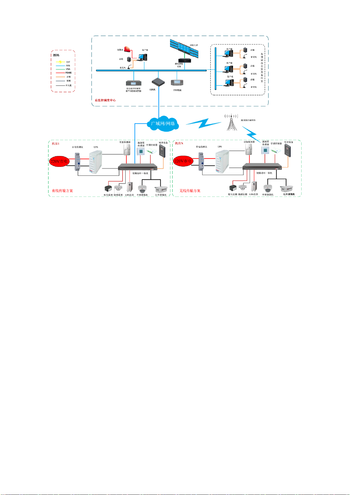
Figure 1-1
Page 9
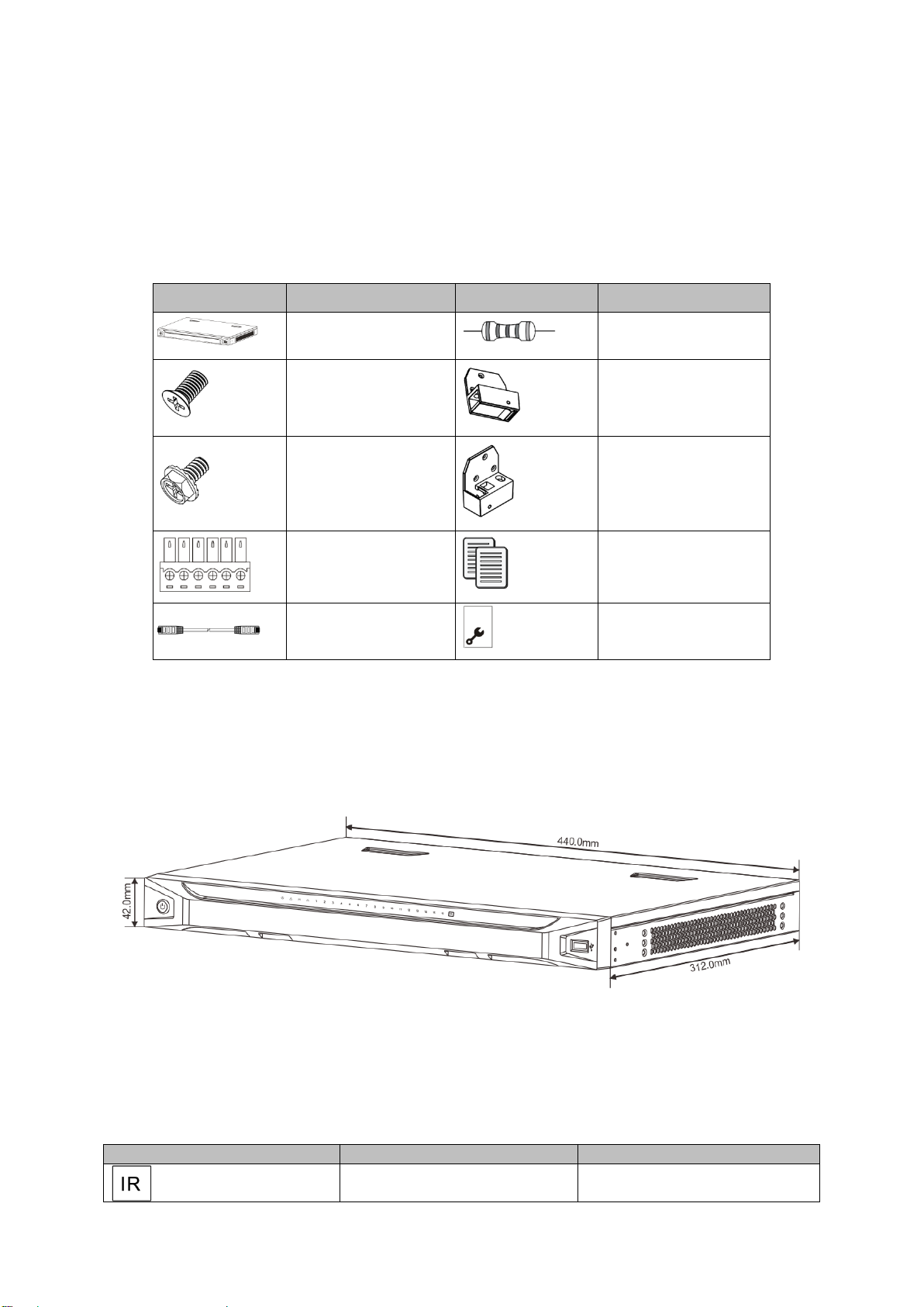
2 Product Structure
Component
Name
Component
Name
Field Surveillance
Unit
2.2kΩ resistance
M3×6 screw
Left hanger
32×6UNC screw
Right hanger
Terminal
Quick start guide
Cable
Warranty card
Symbol
Name
Function
Remote control receiver
indicator
Blue: it is receiving signal from
remote control
2.1 Checklist
Open package of the device; check whether Field Surveillance Unit is damaged referring to Chart
2-1.
Chart 2-1
2.2 Dimensions
Device dimensions is 440mm × 312mm × 42mm(L×W×H), see Figure 2-1.
Figure 2-1
2.3 Front Panel
Front panel includes USB port, power switch and each indicator, USB port can connect USB
mouse or peripheral, and indicators are listed below.
Page 10
Power indicator
Plug the device to power, blue
indicator turns ON
Alarm indicator
Blue: no alarm, and it turns
blue
OFF: alarm occurs.
HDD indicator
Blue: HDD is normal.
OFF: HDD is abnormal, or
capacity warning, it generates
alarm
Network indicator
Blue: network is normal.
OFF: network is abnormal, or
not connected, it generates
alarm
Channel indicator
Blue: channel is normal.
OFF: channel is abnormal.
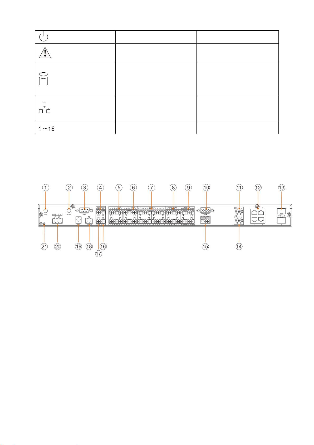
2.4 Rear Panel
See Figure 2-2.
Chart 2-2
Figure 2-2
Page 11

No.
Port Name
No.
Port Name
○
1
GPS antenna
(reserved)
○
12
Network port
○
2
4G antenna
○
13
SFP port
○
3
RS232 serial
○
14
Audio input port
○
4
Smoke sensor port
○
15
Battery port
○
5
RS485
○
16
Siren port
○
6
RS232
○
17
Peripheral power port
○
7
DI port
○
18
Alternate power port
(DC8~48V)
○
8
AI port
○
19
Main power port(DC12V)
○
9
DO port
○
20
Main power port(DC-48V)
○
10
Monitor port
○
21
Grounding screw
○
11
Audio input port
Chart 2- 1
Page 12

3 Installation and Wiring
3.1 Before Installation
Note:
Find external power switch position in case accident occurs during installation and device
maintenance. You can immediately cut off power or unplug device power line if needed.
3.1.1 Select Installation Position
Do not affect the normal operation of device, as far as possible away from heat sources
such as electromagnetic fields or electromagnetic radiation source, easy to leak location,
power inlets and outlets.
Do not install in the room with corrosive acid-base gas.
Do not affect the normal operation of other device, maintenance, and does not occupy
maintenance, security channels and device placeholder.
The location of the module should be placed in the collection room or area, and facilitate the
wiring, and generally cannot exceed 15 meters from serial communication (RS232)
intelligent devices.
In order to facilitate the device wiring and installation, it is recommended that the distance of
device bottom from the installation ground is 1.4 meters or the installation height flushes with
the AC distribution box to maintain the site device overall good appearance.
3.1.2 Common Tool
Glue gun, tape, electric hand drill, rivet gun and rivet, multi-meter, soldering iron and other
common tools.
3.1.3 Requirements for Installation
Cut Line
You must stop the power or signal before cut the line, when unclear whether there is
electricity or signal, do not allow more than two lines cut at the same time(to prevent
short circuits and interference) , only allowing to cut one by one.
Note to use insulated pliers; do not throw the cut line randomly to prevent a short circuit
to ground.
Stripping
Use a sharp diagonal plier to scratch a lap on wire and then pull with force, remove the
insulating layer of wire.
Note that do not cut too deep, otherwise will scratch the metal wire
Wiring
When wiring, separate the two wires that will be connected together for 1.5 cm and up,
followed by two wire twisted tight and together, and then add on solder wire. Respectively
wrap the connected wire with insulating tape tightly, then two wires wrapped are put
together.
Page 13
Note Do not have short glitch exposed on the outside, which will puncture insulating tape
and other cause short circuit of metal, at the same time be sure to wrap in a uniform
appearance, with thickness not less than two layers of insulating tape.
Terminal
Peel the line about 1 cm, (if it is stranded cotton-covered wire, use hands to twist them
together) and fold twice. After terminal is inserted, tighten the terminal screws.
Note that the terminal screws must be very tight, and use hand to pull the inserted wire,
confirm this line is very strong.
Weld
When welding on site, be sure to consider security issues of soldering iron, must be
careful not to damage other device during welding.
3.2 Install Field Surveillance Unit
The device adopts wall mount installation; first install hangers onto device, hang the device on
wall via hanger and finally fix the device with screws.
3.3 Install Peripherals
For instructions, please refer to user’ manual of each peripheral.
3.4 Wiring
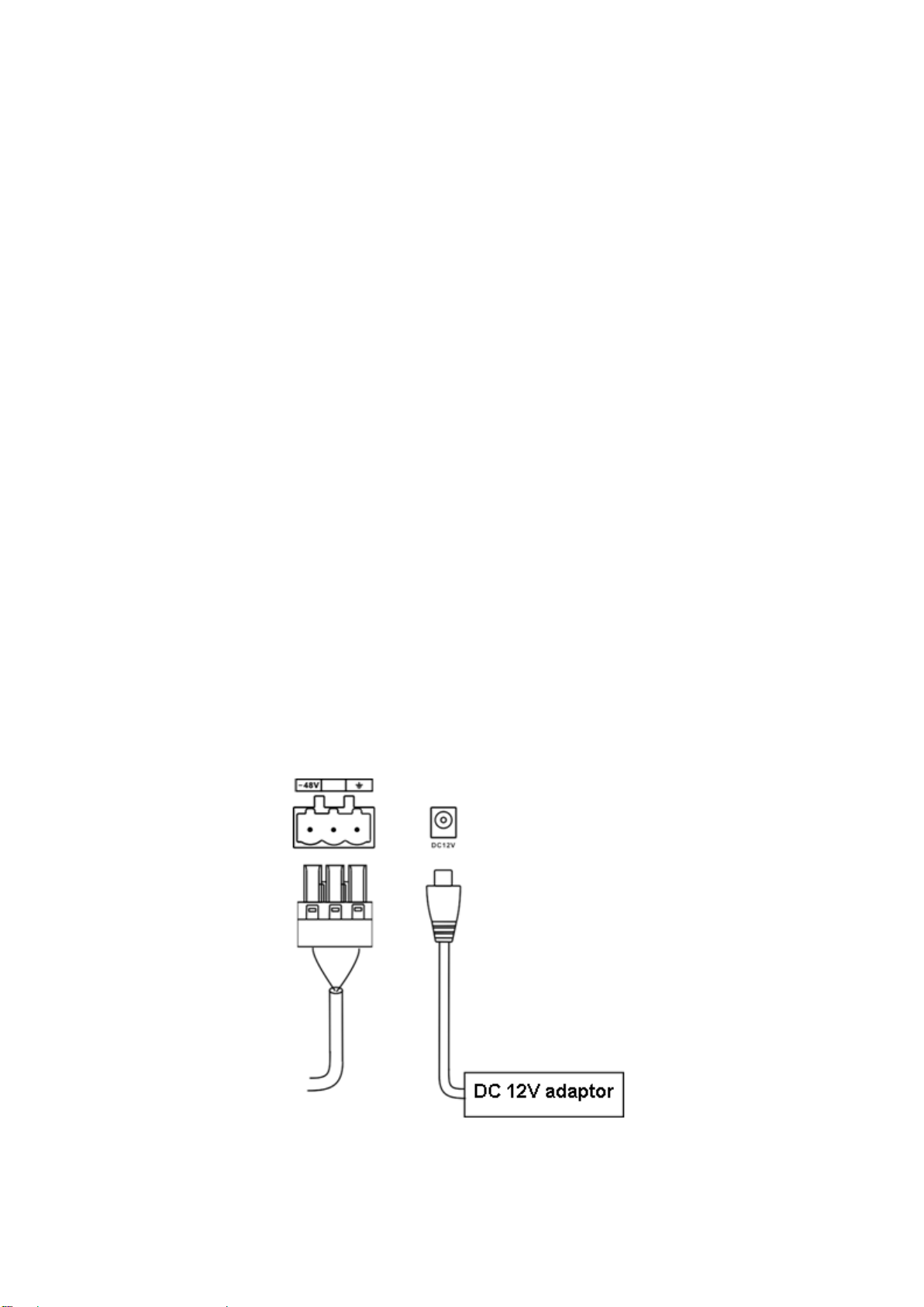
3.4.1 Main Power Wiring
The device provides two methods of main power (DC-48V and DC12V) to power the device, see
Figure 3-1.
3.4.2 Network Port Wring
Figure 3-1
Page 14
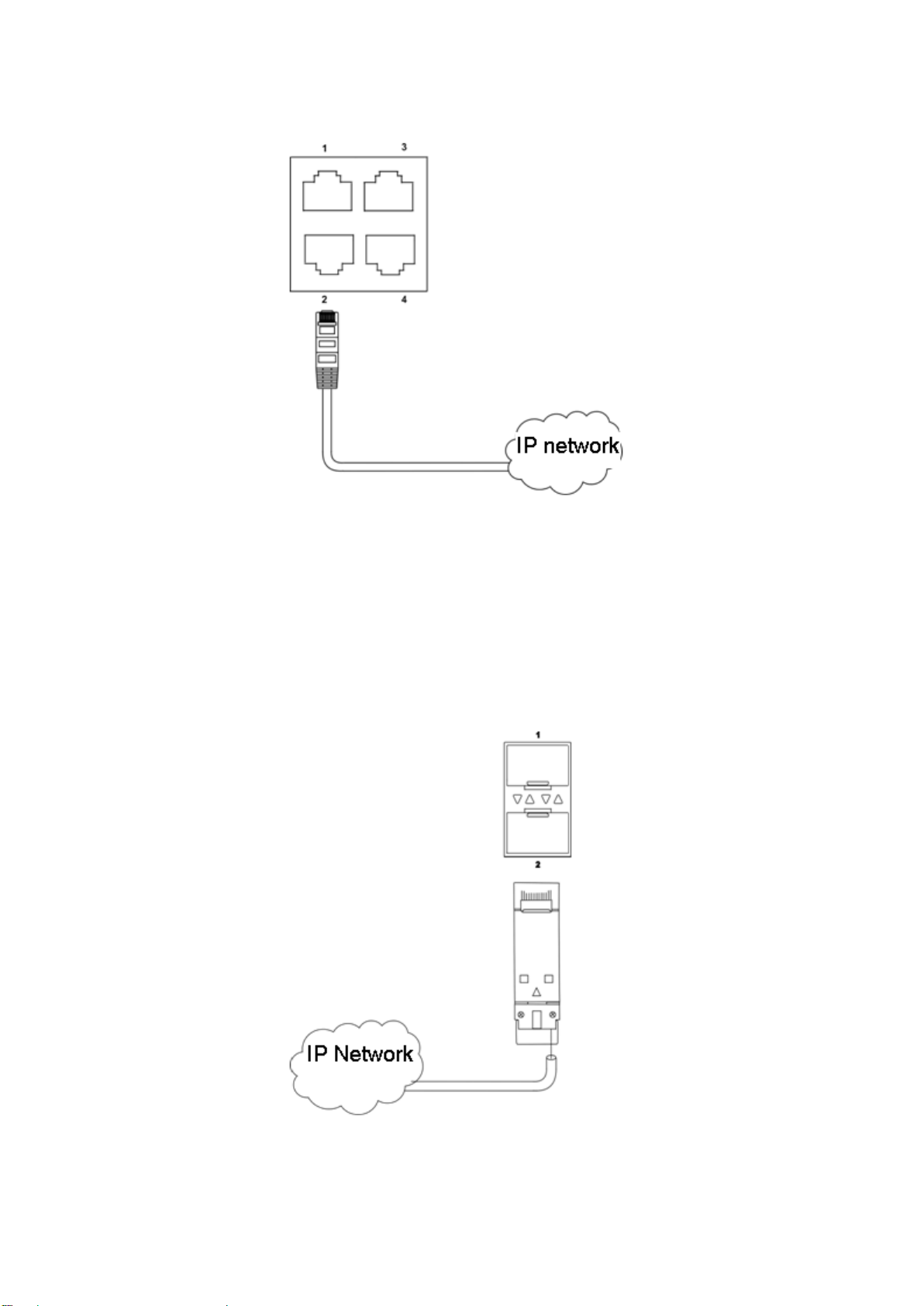
The device provides 4-ch network port, to support exchange and achieve linkage use among
device and PC, device and IPC, or network collection controllers, see Figure 3-2.
Figure 3-2
3.4.3 SFP Port Wiring
The device provides 2-ch SFP port, to support loop network and achieve linkage use among
device and optical exchange, device and device, see Figure 3-3.
Connect fiber wire: after inserting fiber wire into the port, pull up black cover, and insert fiber wire
into the plug.
Remove fiber plug: pull the shifting ring on plug out to take out plug.
Figure 3-3
Page 15
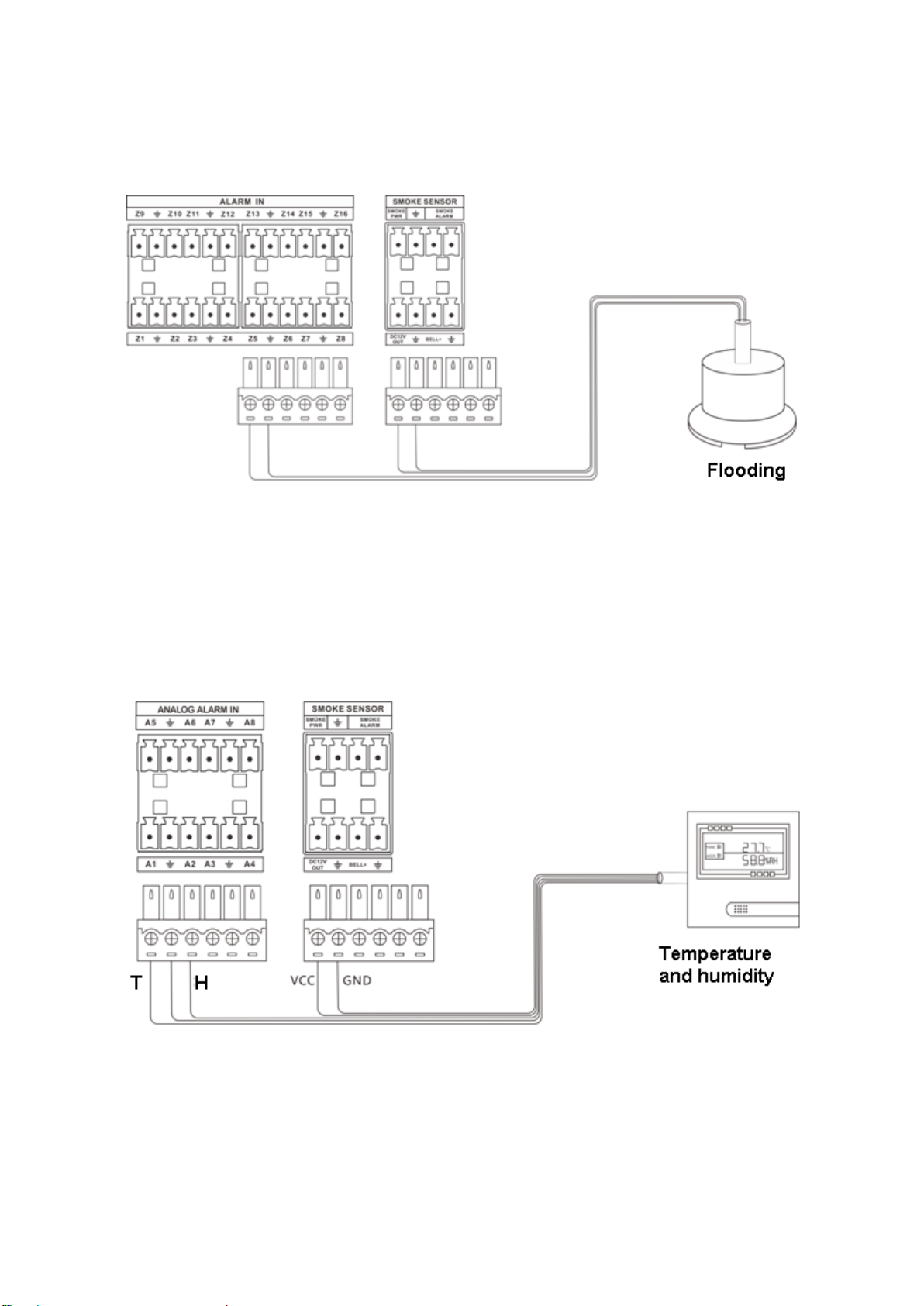
3.4.4 DI Port Wiring
The device provides 16-ch DI port which may connect to passive IR sensor, smoke sensor, pointtype flooding and etc. See Figure 3-4.
Figure 3-4
3.4.5 AI Port Wiring
The device provides 8-ch analog value port, which may connect to temperature/humidity sensor
and other 4~20mA analog value peripherals. See Figure 3-5.
3.4.6 RS 485 Port Wiring
Figure 3-5
Page 16
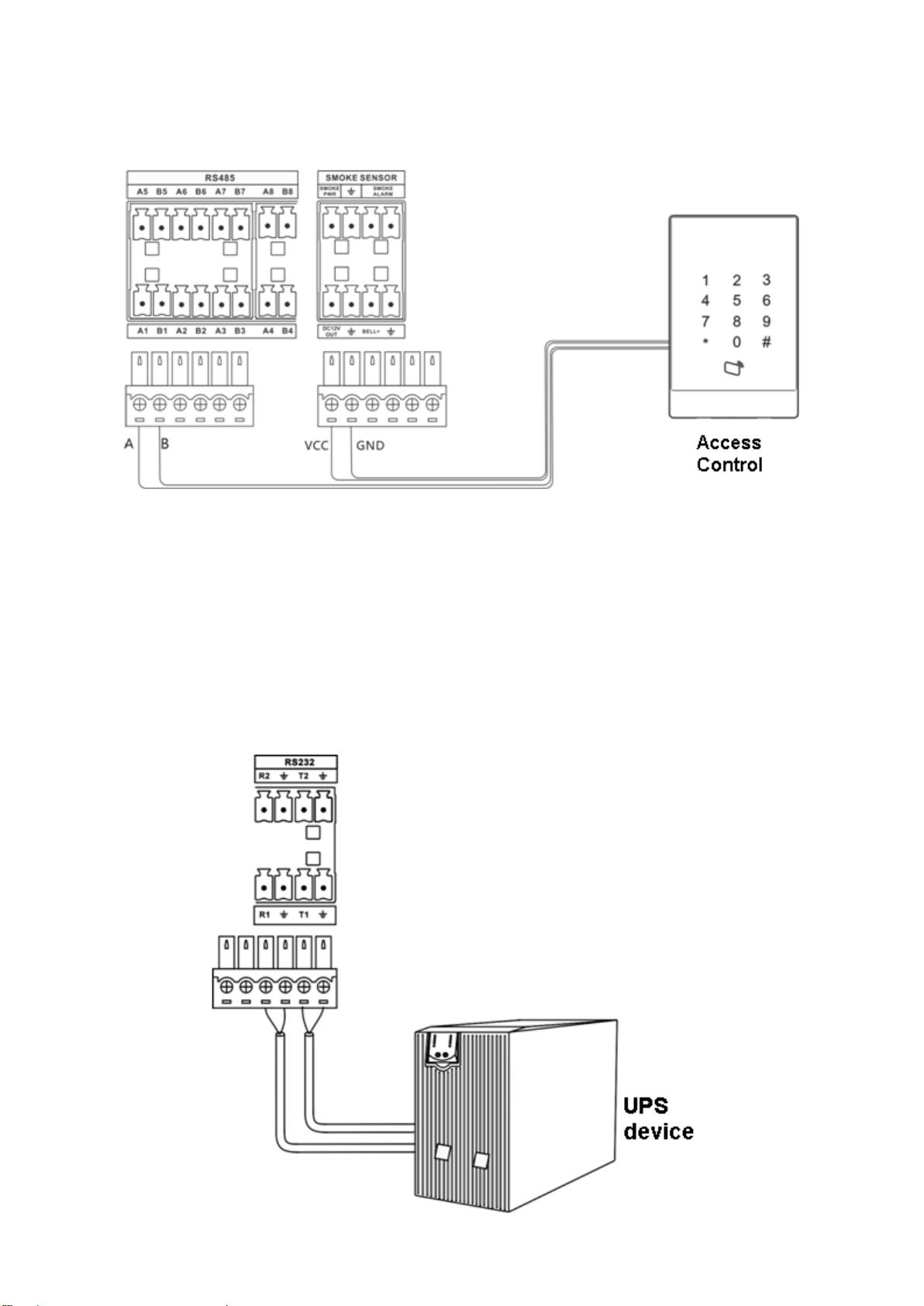
The device provides 8-ch RS485 port, which may connect to PTZ, temperature/humidity sensor,
voltameter/smart meter, access control, distribution switch and smart air conditioner, battery
detector and etc, see Figure 3-6.
Figure 3-6
Note:
Peripheral 485 address must match the corresponding address of port.
3.4.7 RS232 Port Wiring
The device provides 2-ch RS232 port, which may connect to 2 groups of UPS device, see Figure
3-7.
Page 17
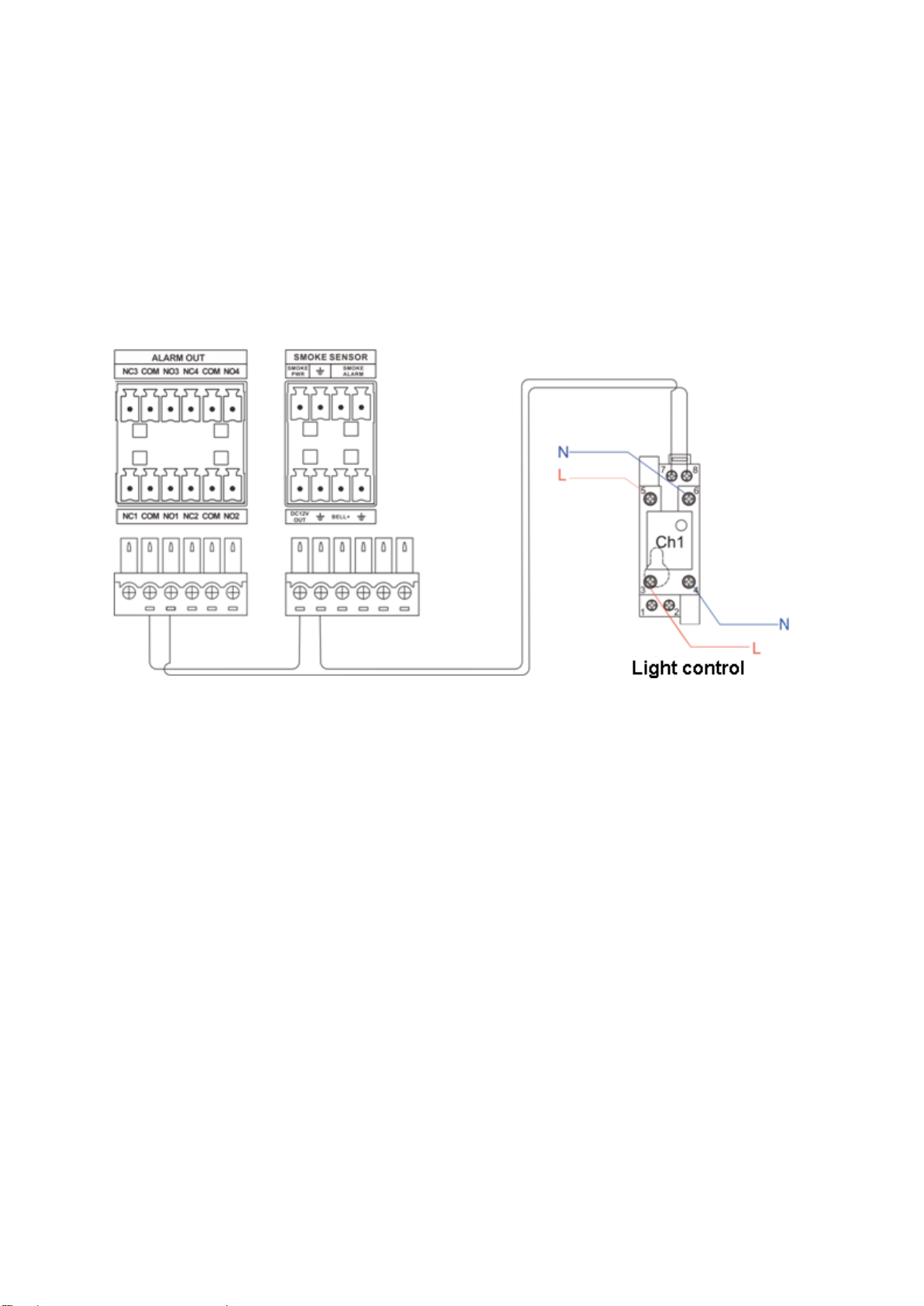
Figure 3-7
3.4.8 DO Port Wiring
The device provides 4-ch wiring (NC, COM, NO), may connect to light control device, see Figure
3-8.
NC: normal close.
NO: normal open.
COM: component object mode, public terminal.
Figure 3-8
Note:
L is fire line, N is null line; or L is phase line, N is neutral line.
Light control device is NO by default, so light is OFF. When alarm occurs, light will be ON.
3.4.9 Smoke Sensor Wiring
The device provides smoke sensor port, connecting to smoke sensor, see Figure 3-9.
Page 18
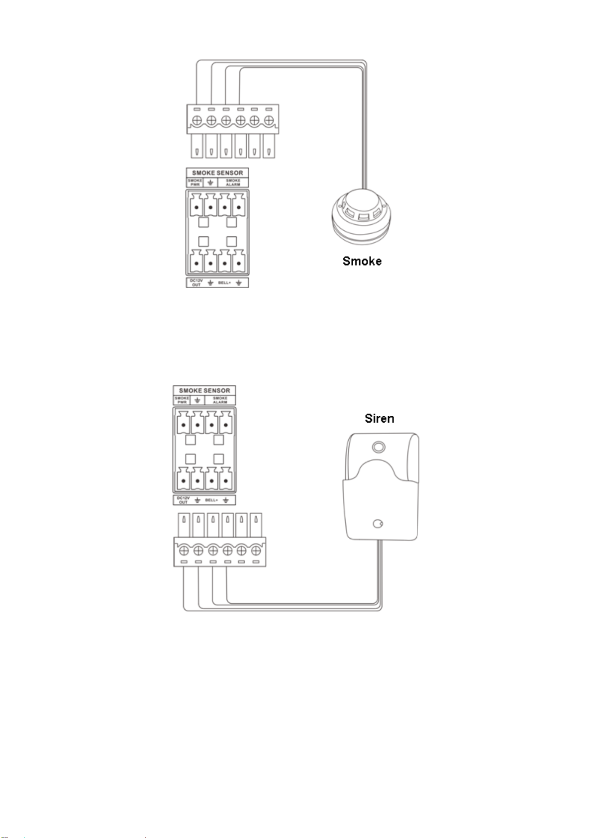
Figure 3-9
3.4.10 Siren Port Wiring
The device provides siren port (BELL+), to achieve siren alarm, see Figure 3-10.
Figure 3-10
3.4.11 Audio Input Port Wiring
The device provides 1-ch audio input port (MIC IN), to connect MIC, pick-up and etc and achieve
audio intercom, see Figure 3-11.
Page 19
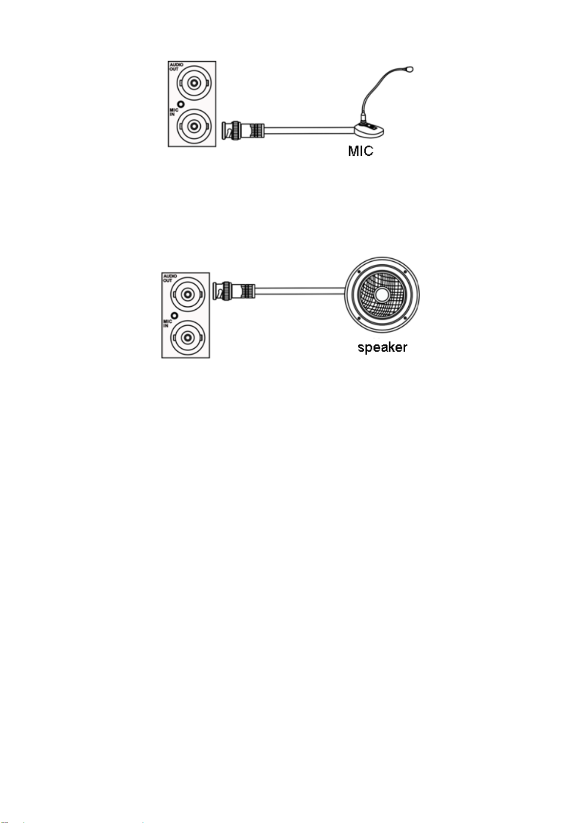
Figure 3-11
3.4.12 Audio Output Port Wiring
The device provides 1-ch audio output port (AUDIO OUT), to connect speaker and etc. which
can play audio, see Figure 3-12.
Figure 3-12
Page 20
4 Boot Up and Operation
4.1 Boot Up
Connect power line, boot up the device. When the device beeps, it completely boots up. See
Chart 2-2.
4.2 Login Web
Please make sure PC and the Field Surveillance Unit are in the same network segment and
there is communication between network port and Field Surveillance Unit.
Note:
Field Surveillance Unit’s initial IP is 192.168.1.108.
At first time login, please follow instructions to install plug in.
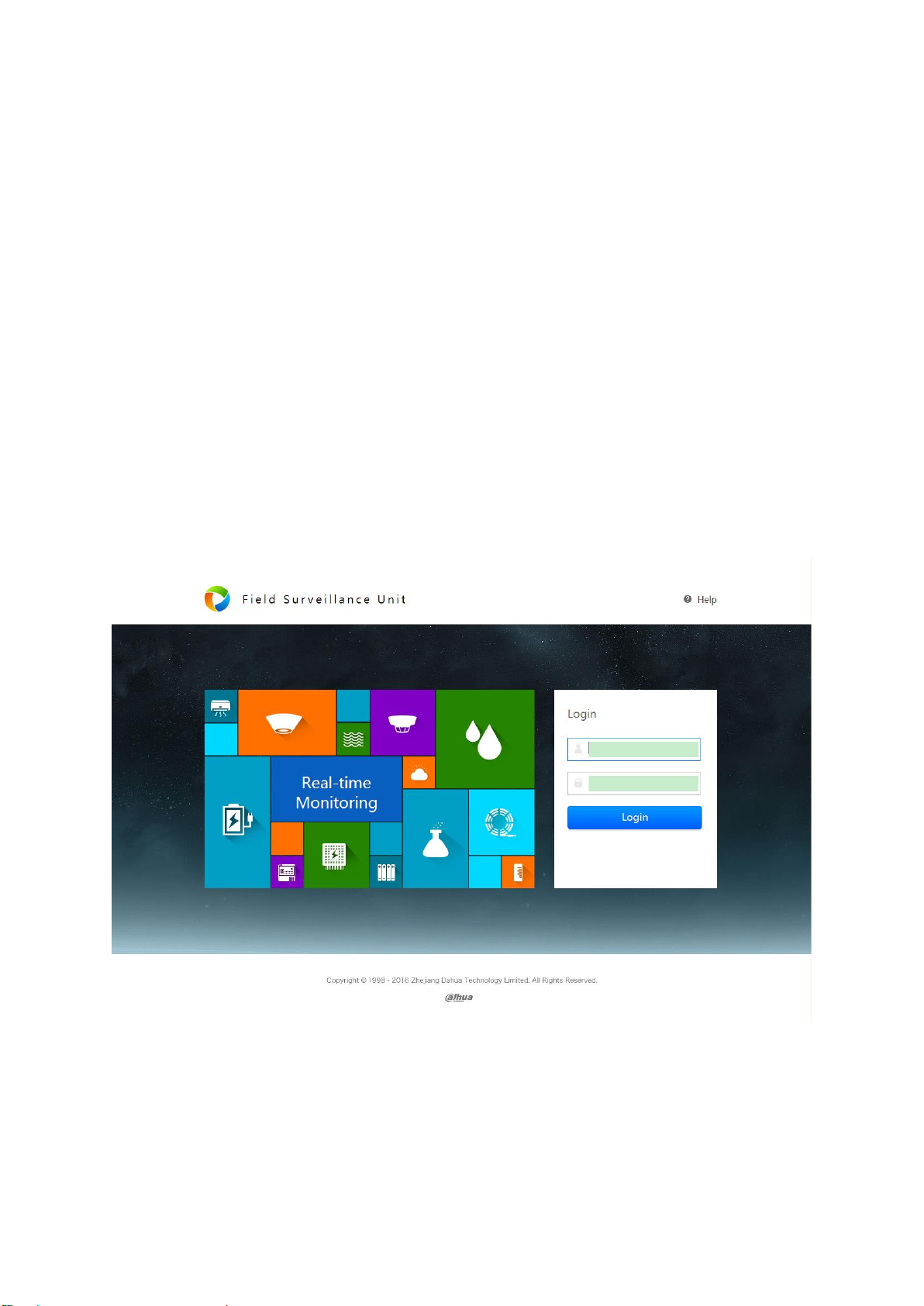
Step 1. In Internet Explorer, input IP add of Field Surveillance Unit, press Enter. You will see
Figure 4-1.
Figure 4-1
Step 2. Enter username and password, click Login to enter homepage.
Note:
Default username and password are both “admin”, please change the password after first time
login.
Page 21
First time login
System shows admin security setup box.
If you want to change password, please enter old password, new password and
confirm password. Click OK.
If you do not want to change password, click Cancel and enter homepage.
Non-first time login. See Figure 4-2.
Figure 4-2
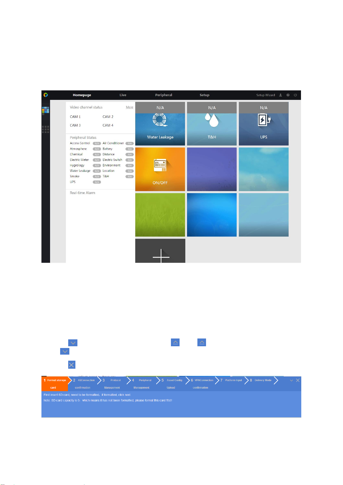
4.3 Setup Wizard
The device provides setup wizard, to quickly set parameters, network connection, peripheral and
platform connection.
Click Setup Wizard at the upper right corner, pop up wizard interface, see Figure 4-3.
Click to hide interface, icon changes to. . Click to unfold interface, icon changes
to .
Click to close interface.
Figure 4-3
4.3.1 Format Storage Card (including SD Card)
Page 22
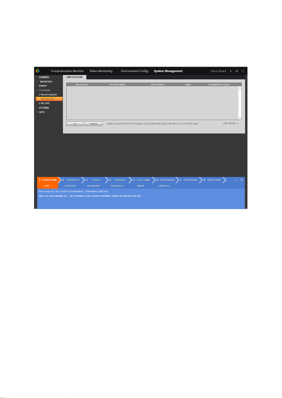
Warning:
When you first time insert SD card, you shall format it. If you have already formatted it, please
skip this step.
Click “1 Format Storage Card”, see Figure 4-4.Select storage card. Click Format, device auto
reboots.
Figure 4-4
4.3.2 4G Connection Status
Click “2 4G Connection Confirmation”, see Figure 4-5. If you get dial IP, manufacturer info and
wireless signal, then means successfully dialed. If not shown, confirm if connection of 4G module
power, USB and antenna are connected rightly if signal strength over -90dBm.
Page 23
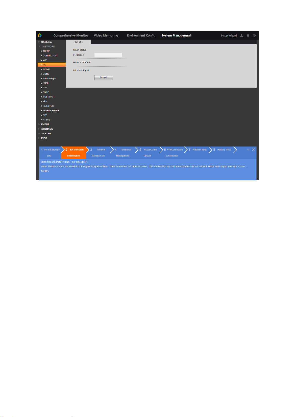
Figure 4-5
4.3.3 Add Peripheral Protocol
Step 1. Click “3 Protocol Management”, see Figure 4-6.
Page 24
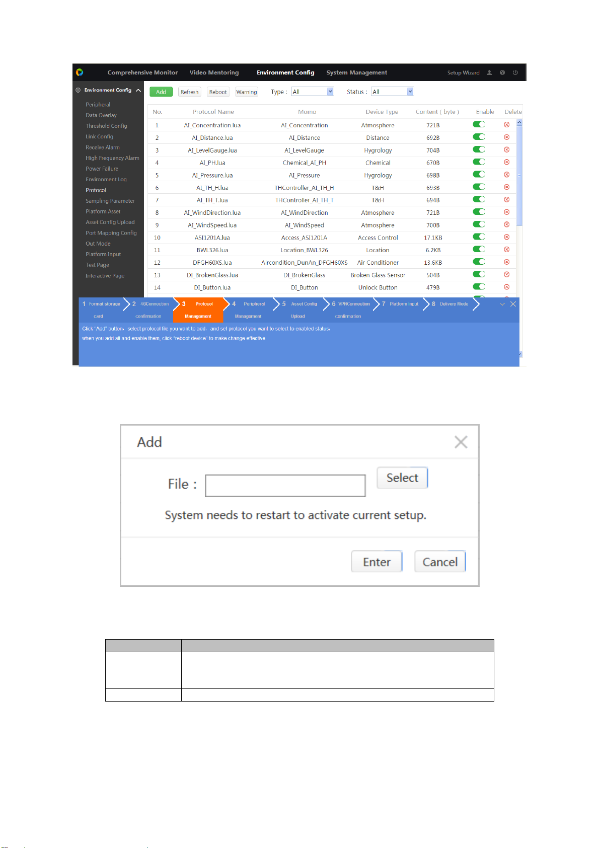
Figure 4-6
Protocol Type
Note
AA_a.lua
Peripheral file, single protocol only provides one peripheral
input. If you need more models of peripheral, need to upload
more protocol.
pointDB
Point database file, need peripheral need to update this file.
Step 2. Click Add, see Figure 4-7.
Figure 4-7
Step 3. Click Select, select file, see Chart 4-1.
Chart 4-1
Step 4. Click Enter to add this protocol into list.
Page 25
Step 5. In the list, find this protocol, click , to enable this protocol, button switches to
.
Step 6. Click Reboot.
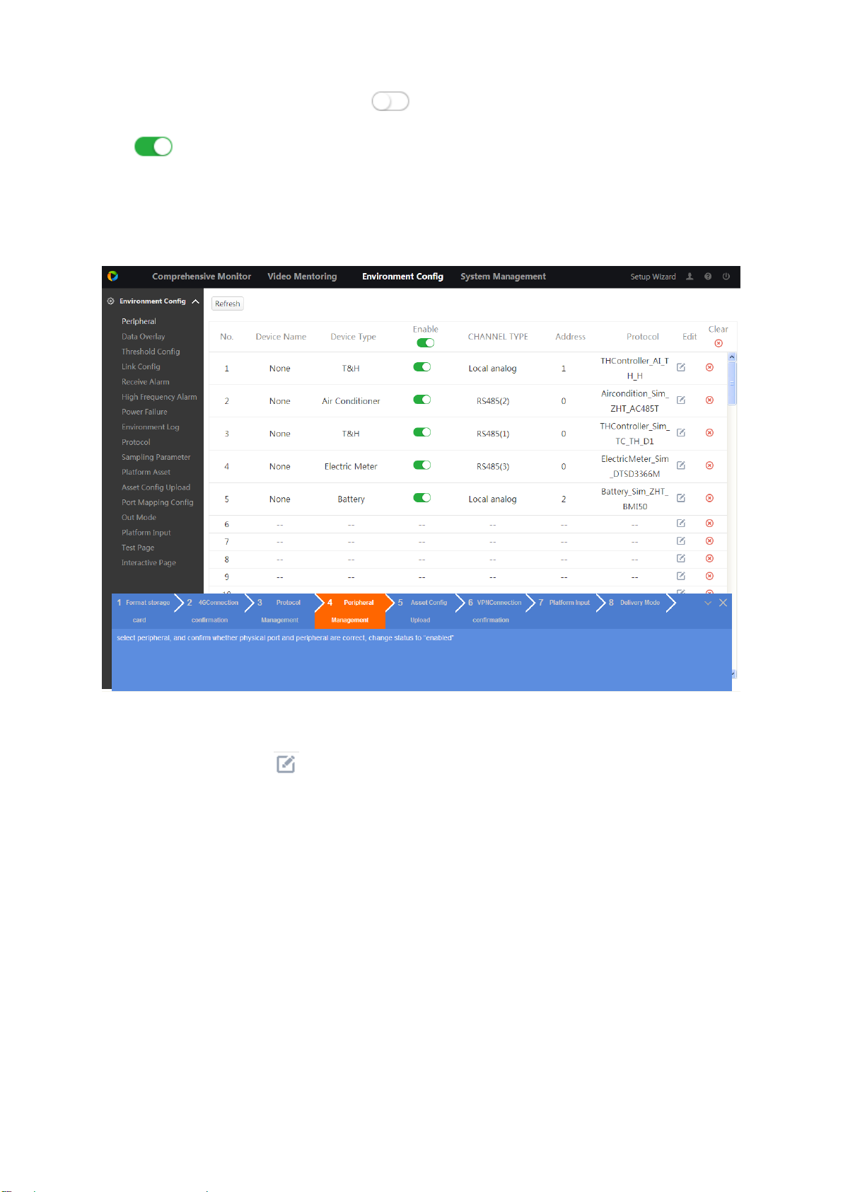
4.3.4 Add Peripheral
Step 1. Click “4 Peripheral Management”, see Figure 4-8. Link peripheral to protocol.
Step 2. In blank row, click .
See Figure 4-9.
Figure 4-8
Page 26
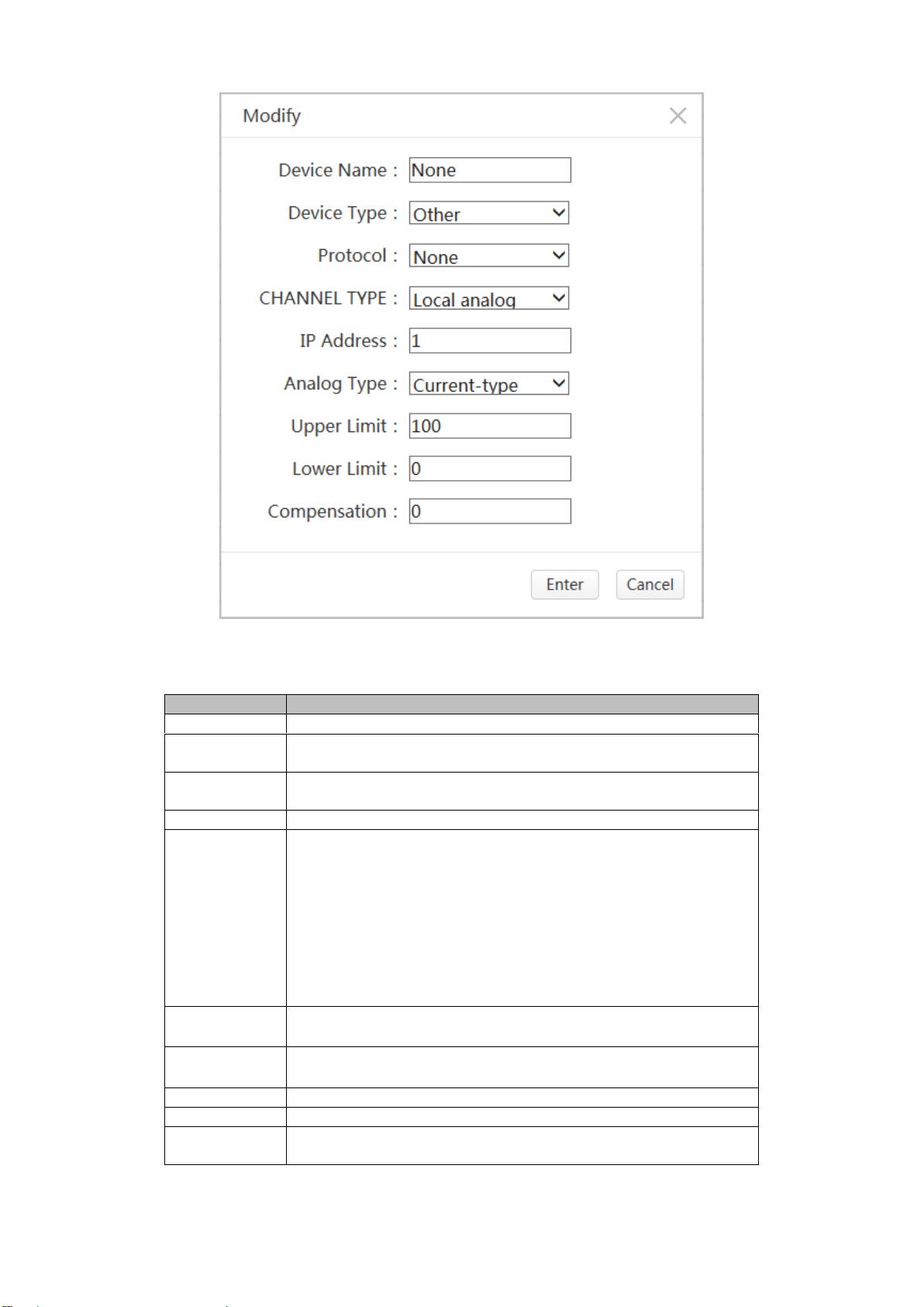
Step 3. Set parameter.
Parameter
Note
Device Name
Customize peripheral name.
Device Type
Peripheral type supported by current device shall match device
type supported in protocol management.
Protocol
Match peripheral one by one, the name of protocol is just
model of peripheral. Please see Ch 5.9.
Channel Type
Physical port type of this peripheral.
Address
Different port types, correspond to different addresses.
Relationships are:
Channel type is local switch ( Z1~Z16 ) , corresponding
address is 1~16.
Channel type is local analog value(A1~A8),corresponding
address is 1~8.
Channel type is RS485/RS232 port, corresponding address is
peripheral actual COM address.
Channel type is network, address by default.
NO/NC
Channel type is local switch quantity(Z1~Z16), need to set
NO/NC according to peripheral type.
Analog Type
Channel type is local analog(A1~A8), need to set current
type and voltage according to peripheral type.
Upper Limit
Set according to actual peripheral.
Lower Limit
Set according to actual peripheral.
Compensation
Value
When measure value and actual value differ, you can calibrate
via compensation value.
Figure 4-9
Chart 4-2
Page 27
Step 4. Click . Enable this peripheral, button siwtch to .
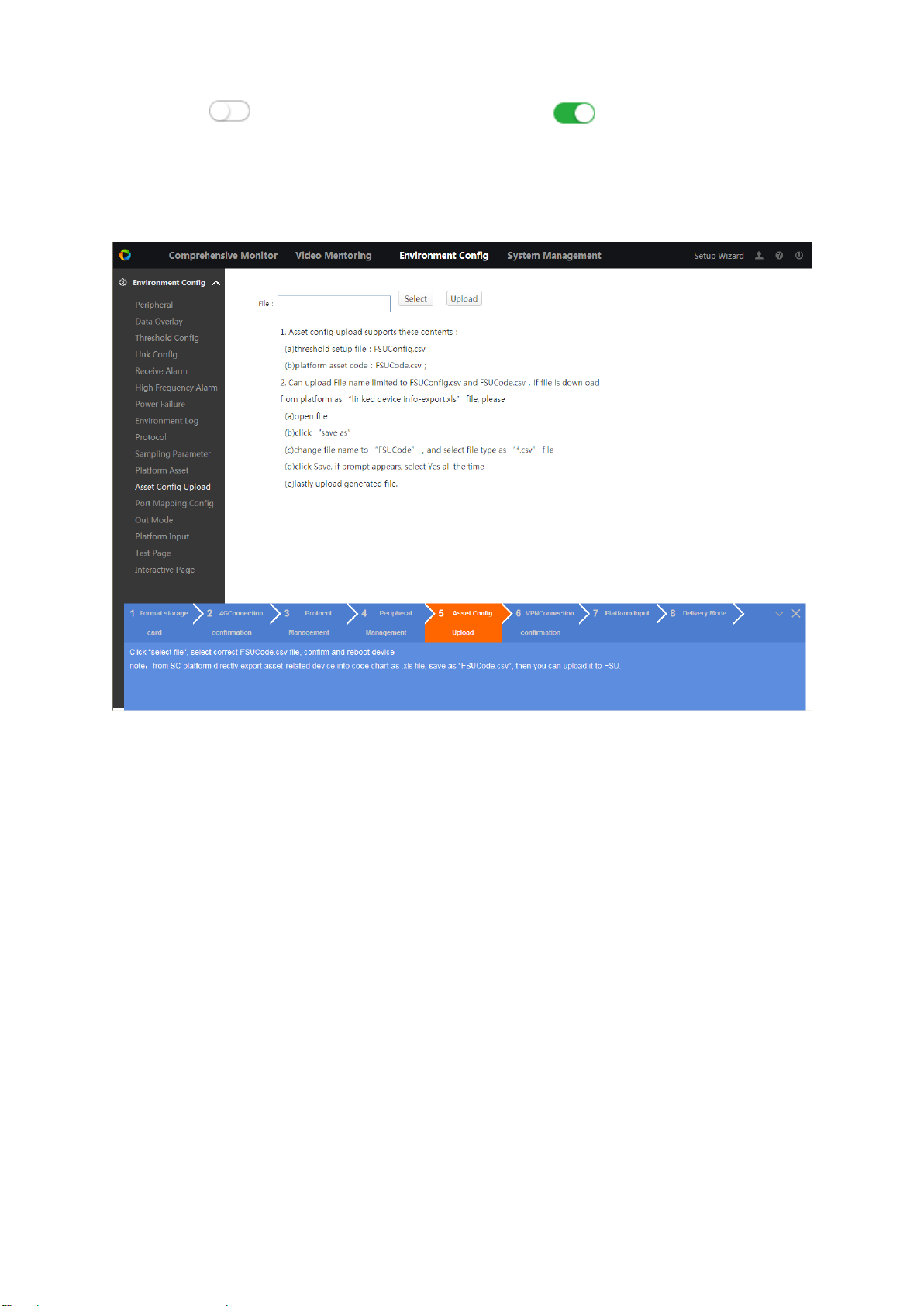
4.3.5 Upload Asset Config
Step 1. Click “5 Asset Config Upload”, see Figure 4-10.
Figure 4-10
Step 2. Click Select, select file.
Note:
File format and naming are strictly ruled.
Step 3. Click Upload.
4.3.6 VPN Connection
VPN is to create virtual network in public network, by encrypting data pack and converting data
pack target address to achieve remote access.
Step 1. Click “6 VPN Connection Confirmation”, see Figure 4-11.
Page 28
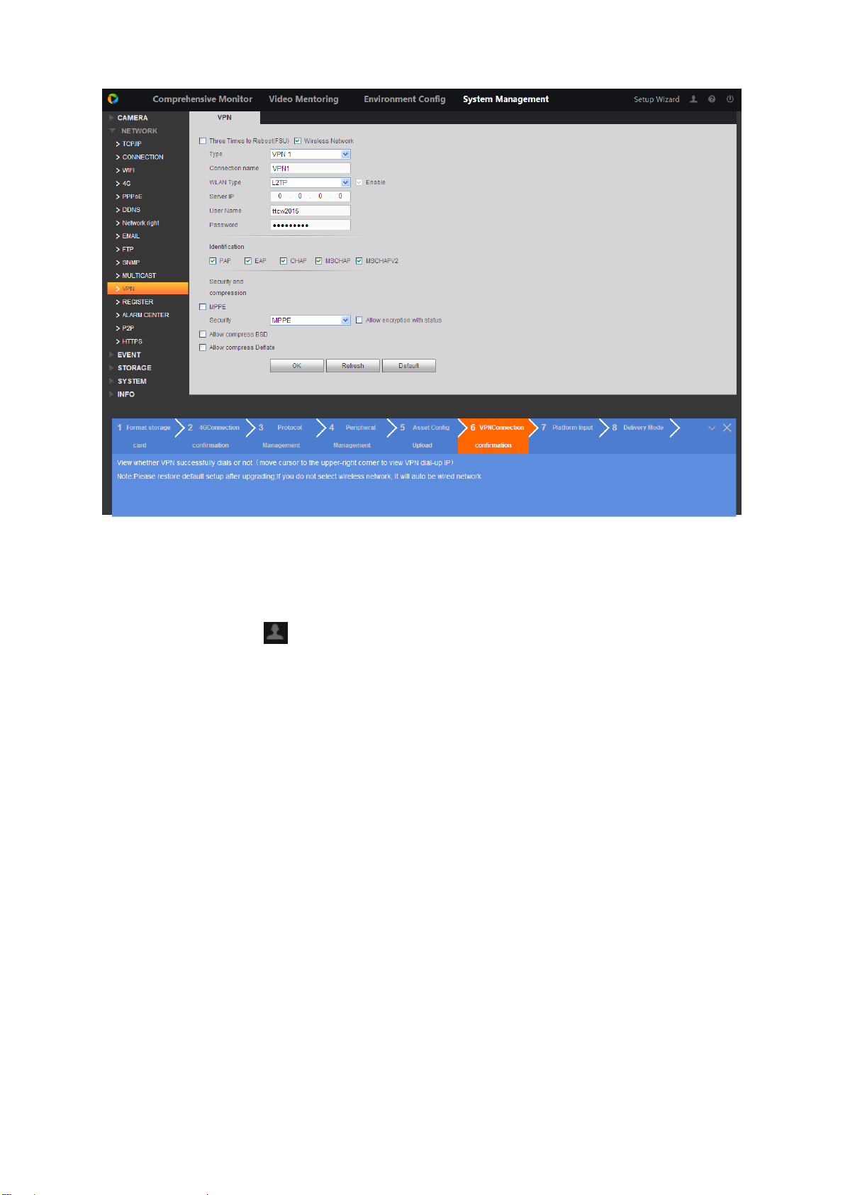
Figure 4-11
Step 2. Set parameter.
Step 3. Click OK.
Step 4. Place mouse on in the upper right to view connection.
4.3.7 Platform Input
Step 1. Click “7 Platform Input”, see Figure 4-12.
Page 29
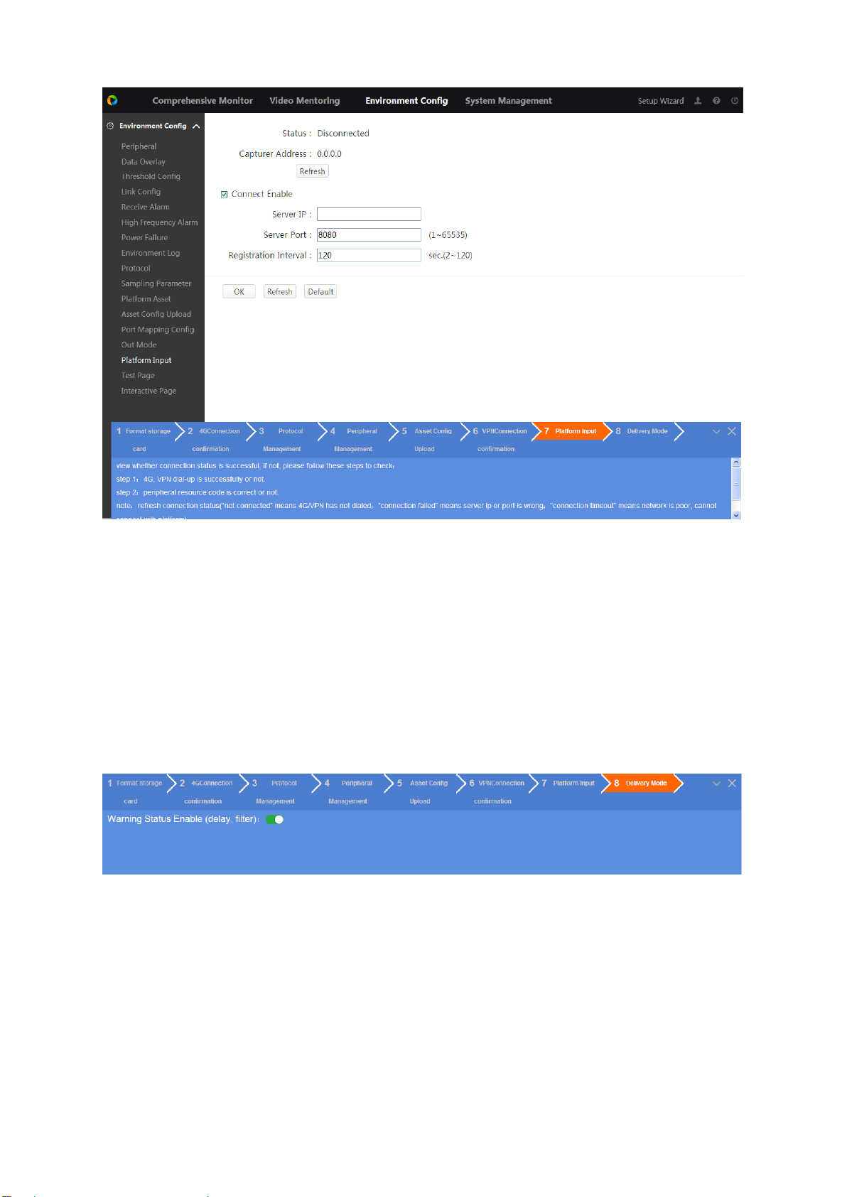
Figure 4-12
Step 2. Check Connect Enable.
Step 3. Enter platform provided server IP, port, registration interval.
Step 4. Click OK.
Step 5. Click Refresh to view whether connection is successful and get sampling address.
4.3.8 Delivery Mode
Used to check wiring and config, quickly deliver.
Click “8 Delivery Mode”, see Figure 4-13.
Figure 4-13
Note:
When disable it, device will not filter warning delay and outage warning. After device reboots, it is
auto enabled.
Page 30
5 Environment Configuration
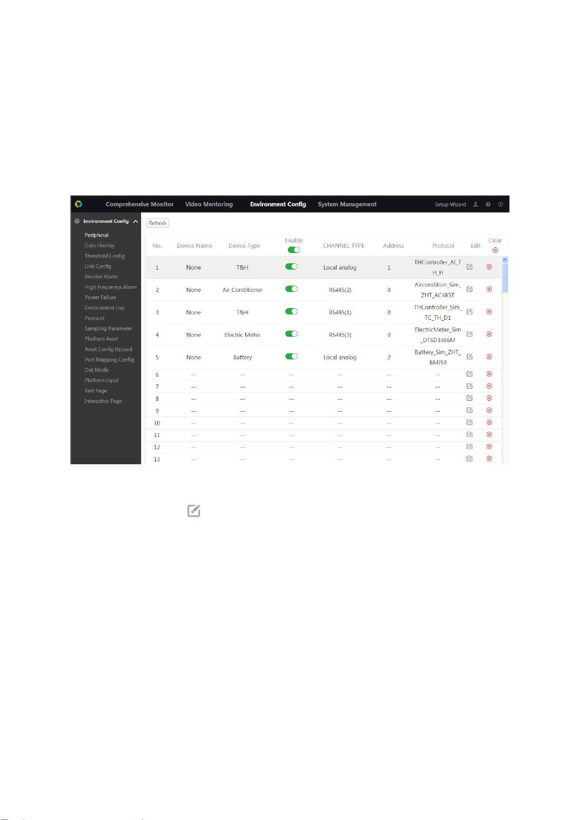
5.1 Peripheral
You must link peripheral to added protocol before you can perform monitoring operation. Select
Environment Config>Peripheral, see Figure 5-1.
Figure 5-1
Step 1. In blank row, click . See Figure 5-2.
Page 31

Step 2. Set parameters.
Parameter
Note
Device Name
For recognition only, may be customized.
Device type
As peripheral type supported by current device,match device
type in Protocol.
Protocol
One to one match peripheral you will connect,protocol name
is the model of protocol. New peripheral shall upload
corresponding protocol referring to Ch 5.9.
Channel type
Physical port connecting the peripheral
Address
Different port type, different address, connection relation is :
channel type is local switch value(Z1~Z16), corresponding
address is 1~16 ; channel type is local analog value
(A1~A8), corresponding address is 1~8;channel type is
serial(RS485/RS232 port),corresponding address is the
actual COM address of peripheral;channel type is network,
address is default.
NO/NC
Channel type is local switch(Z1~Z16), need to set NO/NC
according to peripheral type.
Analog Type
Channel type is local analog quantity(A1~A8), need to set
current and voltage type according to peripheral type.
Upper Limit
Set according to actual peripheral.
Lower Limit
Set according to actual peripheral.
Compensation
Value
When measure value and actual value differ, you can calibrate
via compensation value.
Figure 5-2
Chart 5-1
Page 32

Step 3. Enter.
Step 4. Enable peripheral.
Click in corresponding row, to enable/disable this peripheral, button switches to
.
Click to one-click enable/disable all peripherals.
Modify Peripheral
Step 1. In device info, click . See Figure 5-3,
Figure 5-3
Step 2. Modify parameter as you need.
Step 3. Click Enter.
Delete Peripheral
Click in device row to delete this device.
Page 33

Click to delete all peripherals.
5.2 Data Overlay
By setting data overlay, you can overlay threshold value of s certain peripheral monitoring point
on window of digital channel monitoring window.
Select Environment Config>Data Overlay, see Figure 5-4.
Figure 5-4
Add Data Overlay
Step 1. (Optional) check Enable to enable data overlay function.
Step 2. In dropdown list, select channel no. and font.
Note:
Only digital channel can achieve data overlay.
Step 3. Click Add. See Figure 5-5.
Page 34

Figure 5-5
Step 4. Select device name, and monitoring spot, customize title.
Step 5. Click Enter.
Step 6. Drag yellow module into video box, confirm position to display.
Step 7. Click OK.
Modify Data Overlay
Step 1. Click in device info.
Step 2. Modify parameter as you need.
Step 3. Click OK.
Delete Data Overlay
Click to delete corresponding row.
5.3 Threshold Config
You can set alarm point threshold value of the above added peripheral.
Step 1. Select Environment>Threshold Setup, see Figure 5-6.
Page 35

Figure 5-6
Step 2. In dropdown list, select device name and monitoring spot, to filter monitoring spot.
Remote test: remotely collect peripheral analog date.
Remote signal: remotely collect peripheral switch signal.
Step 3. Modify monitoring spot info.
a) Click . See Figure 5-7.
Figure 5-7
b) Modify threshold value, see Chart 5-2.
Note:
If you set absolute threshold and relative threshold at the same time, it prefers absolute value.
Page 36

Parameter
Note
Door Limit
When a certain remote test datum exceeds door threshold, the device
will alarm.
Delay
When monitoring spot reaches warning limit, system will delay a while
then warns.
Warning
Difference
Used to limit frequent warning.
Too high warning, warning threshold value below door limit-warning
difference, warning disappears.
Too low warning, warning threshold value over door limit+warning
difference, warning disappears.
Absolute
Threshold
Remote test data change range exceed absolute threshold, data will be
saved to database.
Relative
Threshold
Remote test data change range exceed the product of previous remote
test value and relative threshold value, and data will be saved to
database.
Chart 5-2
c) Click OK.
Step 4. (Optional) Click in Enable column to set this spot to key monitoring spot, and
button switches to .
Step 5. (Optional) Click in Enable column to close mentoring, button switches to .
5.4 Link Config
You need to set link parameter, when a certain peripheral reaches alarm point, it can link other
peripherals to alarm. The system provides 16 link groups, and each group can add 16 devices to
link alarm.
Step 1. Select Environment Config>Link Config, see Figure 5-8.
Page 37

Parameter
Note
PTZ
Activation
Check it, select channel and link mode. Link mode includes preset, pointto-point tour, pattern. See Ch 8.7.2
Figure 5-8
Step 2. Select link group, and customize group name.
Step 3. Set link device.
a) Click Add, see Figure 5-9.
Figure 5-9
b) Set device name and monitoring spot.
Step 4. Set parameter.
Page 38

Parameter
Note
Record
Check, select snapshot channel, when alarm occurs, link this channel
record. See Ch 6.4.2.
Record
Delay
When alarm ends, record delays for a while before it stops.
Snapshot
Check, select snapshot channel, when alarm occurs, link this channel
snapshot, snapshot 20 pics each time. See Ch 6.4.3.
Alarm
Output
Check, select alarm output channel, when alarm occurs, link alarm output
port peripheral device.
Alarm Delay
When alarm event ends, alarm delays for a while before it stops.
Voice
Prompts
Check, in dropdown list select audio file, when alarm occurs, link this
audio file. See Ch 6.5.2.
Buzzer
Check, when alarm occurs, buzzer alarms.
Siren
Check, when alarm occurs, it enables siren.
Message
Check, in dropdown list select alarm group, when alarm occurs, it sends
message to user in this group. See Ch 5.5 .
Mail
Check, in dropdown list select alarm group, when alarm occurs, it sends
mail to user in this group. See Ch 5.5 .
Chart 5-3
Step 5. Click OK.
5.5 Receive Alarm
You can set receiving alarm contact, and the system provides 3 receiving alarm group setup.
Select Environment Config>Receive Alarm, see Figure 5-10.
Figure 5-10
Page 39

Add Receive Alarm
Step 1. Select Receive Alarm Group. Double click group name to customize name.
Step 2. Click Add. See Figure 5-11.
Figure 5-11
Step 3. Enter contact name, mobile phone, mail address and organization. Click Enter.
Step 4. Click Enter.
Modify Receive Alarm
Step 1. Click .
Step 2. Modify info accordingly.
Step 3. Click Enter.
Delete Receive Alarm
Click to delete one contact.
Check multiple contact, click Delete to batch delete contacts.
5.6 High Frequency Alarm
Set period and max alarm number, then when a certain alarm info has been reported exceeding
max alarm limit within the period, the system will treat it as high frequency alarm, and shield this
alarm info. If alarm within the period has not reached max alarm limit, then system cancel high
frequency alarm.
Step 1. Select Environment Config>High Frequency Alarm, see Figure 5-12.
Page 40

Figure 5-12
Step 2. Set statistical cycle (period) and max alarm.
Statistical cycle: time interval of each time alarm count, unit is second, max1800s.
Max alarm: within the statistical cycle, max alarm log number received by the system,
unit is item, which is 6 by default.
Step 3. Click OK.
5.7 Power Failure
When alarms occur due to power failure, high voltage, low voltage, or lack of equal status, the
other alarm points can be set as "filtering monitoring points" to filter out these linkage alarm
messages when other devices generate linkage alarms. .
For example, because the main power-down, resulting in air-conditioning also power-down, this
time will also produce the main power failure alarm information and air conditioning power failure
alarm information. If the main power failure is set to "display monitoring point", air conditioning
power failure is set to "filter monitoring point", you can filter air conditioning power failure alarm
information, only displaying the main power failure alarm information.
Step 1. Select Environment Config>Power Failure, see Figure 5-13.
Page 41

Step 2. Click . See Figure 5-14.
Figure 5-13
Figure 5-14
Step 3. According to actually connected peripheral, check show monitor point and filter monitor
point. Click Enter.
Click to delete this monitor fiter result.
5.8 Environment Log
Page 42

Used to filter, view and back up log.
Step 1. Select Environment Config>Environment Log, see Figure 5-15.
Figure 5-15
Step 2. In dropdown list select device name, monitor spot, and period.
Step 3. Click Search.
See Figure 5-16.
Click to switch image display.
Click Export to export log info to local.
Figure 5-16
Page 43

5.9 Protocol
Warning
After you add or delete protocol, you must reboot the device to make adding/deleting
valid.
Add relative peripheral protocol, to link video field surveillance unit and peripheral.
Step 1. Select Environment Config>Protocol, see Figure 5-17.
Figure 5-17
Click Warning, to enable/disable warning delay.
Click to delete this protocol.
Step 2. Click Add. See Figure 5-18.
Figure 5-18
Page 44

Step 3. Click Select, select file, see Chart 5-4.
Protocol Type
Note
AA_a.lua
AA_a.lua:peripheral protocol file,one protocol can only
provide one peripheral input, if you connect to multiple
models of peripheral, you must upload multple protocols.
AA is peripheral model, a represents peripheral no.(1, 2,
3). For MDDH9901DC,if you want to input 3 units at the
same time, you must upload such protocols as
MDDH9901DC_1.lua;MDDH9901_2.lua;
MDDH9901DC_3.lua
pointDB
Point position database file, new peripheral will need to upload
this file.
Chart 5-4
Step 4. Click Enter.
Step 5. In list find this protocol info, click , enable this protocol and button switches to
.
Step 6. Click Reboot to reboot the device.
5.10 Sampling Parameter
You can set collection period and storage count and collect peripheral change info.
Step 1. Select Environment Config>Sampling Parameter, see Figure 5-19.
Figure 5-19
Step 2. Set collection cycle and storage count.
Collection cycle: time interval between each time of collection, unit is second, range is 1~60.
Storage count: Max log quantity can be stored by the system, range is 1~5000.
Step 3. Click OK.
5.11 Platform Asset Code
Step 1. Select Environment Config>Platform Asset. See Figure 5-20.
Page 45

Figure 5-20
Step 2. In dropdown list select station name, enter province/state and city. Below show platforms
connected to this station.
Step 3. In New Asset Code box, enter new code.
Step 4. Click OK.
5.12 Asset Config Upload
Step 1. Select Environment Config>Asset Config>Upload. See Figure 5-21.
Page 46

Figure 5-21
Step 2. Click Select, select file ended in “.cvs”.
Step 3. Click Upload. Log in web again.
5.13 Port Mapping Config
Bind environment port with network device IP, port no. to input network device.
Select Environment Config>Port Mapping Config, see Figure 5-22.
Figure 5-22
Page 47

Add Port Mapping
Step 1. Click Add, see Figure 5-23.
Figure 5-23
Step 2. Select device type, fill in device IP and port.
Step 3. Click Enter.
Modify Port Mapping
Step 1. Click . See Figure 5-24.
Step 2. Modify parameter.
Step 3. Click Enter.
Delete Port Mapping
Figure 5-24
Click to delete one port mapping info.
Page 48

Check multiple mapping info, click Delete to batch delete.
5.14 Out Mode
Step 1. Select Environment Config>Out Mode. See Figure 5-25.
Figure 5-25
Step 2. Select each channel out mode, as manual, auto and off.
Step 3. Click OK.
5.15 Platform Input
Input platform device into video field surveillance unit, and collect platform data for monitoring.
Step 1. Select Environment Config>Platform Input. See Figure 5-26.
Page 49

Figure 5-26
Step 2. Check Connect Enable, to enable platform input.
Step 3. Enter server IP, server port and registration interval of platform.
Step 4. Click OK.
Step 5. Click Refresh to see if connection is successful.
5.16 Test Page
Used to test whether system runs normally or not and whether peripheral connection is OK.
Select Environment Config>Test Page, see Figure 5-27.
Figure 5-27
5.17 Interactive Page
For the poor upstream network, or in order to improve the interactive speed, alarm signals
triggered by environmental peripherals will be sent to interactive page. Upon network recovery or
in background operation those signals then be reported to platform together.
Remote signal: each type of switch signal of remote peripherals
Remote test: each type of analog data of remote peripherals
Step 1. Select Environment Config>Interactive Page, see Figure 5-28.
Page 50

Figure 5-28
Step 2. In dropdown list select view type. The list below shows related type of device monitoring
info.
When it shows remote signal device, you can operate All Start and All Stop.
Page 51

6 Setup
6.1 Camera
6.1.1 Remote Device
A user can manually or automatically add remote devices and modify, delete and update info.
6.1.1.1 Add Remote Device
Step 1. Select Setup>Camera>Remote Device, see Figure 6-1.
Figure 6-1
Note:
If the device you want to add has the same IP and TCP port with existing device list, you will
not be able to add this device.
Max 4 remote devices supported by the device.
means successful connection, and means failed connection.
Step 2. Add remote device.
Search to add
Step 1. Click Device Search, list shows searched device info.
Step 2. Double click the device info or select the check box in front of device info,
then you can add it into list.
Manually add
Step 1. Click Manual Add. See Figure 6-2.
Page 52

Parameter
Description
Channel
Remote device’s channel number in local device. Configure remote
devices in the corresponding passage in the local device. For example, if
you configure a channel name, the corresponding channel number is
used.
Manufacturers
Select in the drop-down box according to the actual situation. Adding
support for these manufacturers:
Panasonic, Sony, Dynacolor, Samsung, Axis, Arecont, Onvif like.
IP Address
Enter the IP address of the remote device.
RTSP Port
Enter the remote device RTSP port number, the default is 554.
HTTP Port
Enter the remote device HTTP communication port number, 80 by
default.
TCP Port
TCP port to provide communications services, according to the actual
needs of users. The default is 37777.
Username /
Password
Enter the user name and password to log into the remote device.
Remote
Channel No.
The channel number of channels needed to connect remote devices.
Decode Buffer
Including the default, real-time, smooth cases.
Service Type
Including the automatic, TCP and UDP.
Figure 6-2
Step 2. Set parameter, see Chart 6-1.
Chart 6-1
Step 3. Click OK.
6.1.1.2 Modify or Delete Remote Device
Modify device info
Page 53

Click or double click one added device, pop up modify box, see Chart 6-1 and modify
Parameter
Note
Stream type
Activity controlled frame rate (ACF) feature, use a different frame rate for
video, high frame rate recording for an important event, for timed events using
a low frame rate video, motion detection and alarm recording frame rate can
be set individually.
Main stream including ordinary stream, motion detection and alarm stream.
For different events you can choose different video streams.
Secondary stream supports only the ordinary stream.
Enable
video
Select Enable to open the secondary stream, by default.
Encoding
mode
Video encoding mode, with the following options:
H.264: Main profile encoding.
MJPEG: High-definition video streams are needed to ensure
the image quality. In order to make the video image to achieve better
results, we recommend choosing the maximum value among our
parameter. Click OK.
Delete device
Click in added device list to delete the device.
In added device list, check multiple check, click Delete to batch delete remote device.
6.1.2 Encode
You can set video stream, snapshot stream, video overlay and storage path.
6.1.2.1 Encode
Step 1. Select Setup>Camera>Encode>Encode. See Figure 6-3.
Figure 6-3
Step 2. Select channel no., set video stream, see Chart 6-2.
Page 54

reference stream values.
Resolution
Video resolution. The maximum resolution of different devices may be
different, please refer to the actual interface.
The main stream resolution types are 1920 * 1080 (1080p),
1280 * 1024 (SXGA), 1280 * 960 (1.3M), 1280 * 720 (720P), 704 * 576
(D1).
The auxiliary stream resolution type is 704 * 576 (D1), 352 *
288 (CIF).
Frame rate
The number of frames per second video included. The higher the frame rate,
the more realistic and smooth the image. The frame rate varies depending on
the resolution.
Stream
control
Video stream control mode.
Limited stream: the stream is a fixed value.
Variable bit stream: the stream will change with the scene and
so on.
Note:
When Encoding Mode is set to MJPEG, the bit stream control mode can only
be fixed code stream.
Code
stream
value
Main stream: set the stream value to change the quality of
picture quality, the higher the code value, the better picture
quality. The reference code stream value provides the best reference
range.
In the fixed picture stream mode, the code stream value is the
upper limit of the code stream; under the dynamic picture, if
necessary, by reducing the frame rate and picture quality to ensure
that the code stream does not exceed this value; in the variable bit
stream mode, the value does not make sense.
Reference
code stream
value
The best code stream range recommended to the user according to the
resolution and frame rate user configured.
Enable
audio
Select the check box indicates that the feature is enabled. When audio is
enabled, the recording file is an audio / video composite stream.
Note:
Video Enable must be selected first before enable audio in Sub Stream.
Chart 6-2
Step 3. Click OK.
6.1.2.2 Snapshot
Step 1. Select Setup>Camera>Encode>Snapshot. See Figure 6-4.
Page 55

Figure 6-4
Parameter
Note
Mode
As timing, event and trigger.
Timing is to snapshot within set time, see Ch 6.4.2.1.
Event is to snapshot when alarm linked.
Image
Size
Set according to front-end device image size.
Image
Quality
Set image quality within 6 levels.
Snapshot
Frequenc
y
Set snapshot frequency.
Step 2. Select Channel no., set parameter, see Chart 6-3.
Chart 6-3
Step 3. Click OK.
6.1.2.3 Video Overlay
Step 1. Select Setup>Camera>Encode>Overlay. See Figure 6-5.
Figure 6-5
Step 2. (Optional)Set cover area.
Note:
When you want to cover certain part of video for privacy, you can set cover area.
1. Check Monitor, see Set button on the right.
Page 56

2. Click Set, on left press mouse/right click to draw cover area. System supports to 4 cover
areas.
Select area box, click delete or right click mouse to delete corresponding area.
Click clear to delete all area boxes.
Step 3. (Optional) Set channel title.
Note:
When you need to show channel title in video, you can set channel title.
1. Check channel display, see Set button on the right.
2. Click Set to enter title.
3. Drag channel box on the left to adjust position.
Figure 6-6
Step 4. (Optional) Set time title.
Note:
When you need to show time in video, you can set time title.
1. Check Time Title, see Set button on the right.
2. Click Set to enter title.
Drag time box on the left to adjust position.
Figure 6-7
Page 57

Step 5. Click OK.
Click Copy to copy this config to other channels.
After being saved, in Live, select channel to view, see Figure 6-8.
Figure 6-8
6.1.2.4 Path
Step 1. Select Setup>Camera>Encode>Path. See Figure 6-9.
Figure 6-9
Step 2. Click Browse, select snapshot path and record path.
Default path is PictureDownload and RecordDownload in system disk.
Step 3. Click OK.
Click Default to restore default setup.
6.1.3 Cam Name
Used to mark each channel.
Note:
Set channel name, monitor interface and overlay setup interface, which will sync the latest
channel name and title.
Page 58

Step 1. Select Setup>Camera>Cam Name. See Figure 6-10.
Parameter
Note
Network Card
Default is “Network Card1”.
IP Version
You can select IPv4 and IPv6. Currently there are two types of IP address
supported.
MAC Address
Show device MAC address.
Figure 6-10
Step 2. Enter channel name.
Step 3. Click OK
6.2 Network
6.2.1 TCP/IP
Note:
Before you set network, please confirm that Field Surveillance Unit has been properly connected
into the Internet.
Step 1. Select Setup>Network>TCP/IP, see Figure 6-11.
Figure 6-11
Step 2. Set TCP/IP parameter, see Chart 6-4.
Page 59

Parameter
Note
Mode
Static
Manually set IP address, subnet mask, gateway.
DHCP
Auto get IP function. When enable DHCP, “IP Address”, “Subnet mask”
and “Default Gateway” cannot be set.
If currently DHCP is valid, then IP/mask/gateway show DHCP to get
value. If invalid, IP and etc. are 0.
To check the current IP, if DHCP does not take effect, turn off DHCP first
to display the IP information obtained by non-DHCP automatically. If
DHCP is enabled, then turn off DHCP cannot show the original IP
information, need to re-set IP related parameters.
"IP Address, Subnet Mask, Default Gateway and DHCP cannot be
changed when PPPoE dialing is enabled.
IP Address
Enter planned IP address.
Subnet Mask
According to the actual situation, subnet prefix is digital, input 1 ~ 255,
subnet prefix part identifies a specific network link, usually includes a
hierarchical structure.
Note:
The device checks the validity of all IPv6 addresses. The IP address and
the default gateway must be in the same network segment. That is, the
segment with the specified length which the subnet prefix defines must be
the same to pass the test.
Default
Gateway
According to the actual situation, the IP
address must be in the same network
segment.
Note:
IPv6 version IP address,
default gateway, preferred
DNS, alternate DNS input is
128 bits, cannot be empty.
Preferred DNS
DNS server IP address.
Alternate DNS
DNS server backup IP address.
MTU
Used to set the MTU value of the network card, the setting range is 1280
bytes to 7200 bytes and the default is 1500. Modifying the MTU will cause
the network card to be restarted and the network interruption will affect the
running network service. When MTU modification is saved, Dialog box to
confirm that the device reboots. If the user cancels the restart, the
modification does not take effect.
Note:
MTU recommended value:
1500: The maximum and default value for Ethernet packets. The
typical settings for network connections without PPPoE and VPN are
the default settings for some routers, network adapters, and switches.
1492: The best value of PPPOE.
1468: the best value for DHCP.
1450: the best value of VPN.
Chart 6-4
Step 3. Click OK.
6.2.2 Port
You can set device’s max connection ports in this interface and each port value.
Step 1. Select Setup>Network>Port, see Figure 6-12.
Page 60

Figure 6-12
Parameter
Note
Max
Connection
The number of clients allowed to log in at the same time (with WEB client,
platform client, mobile client, etc.).
TCP Port
TCP protocol communication port to provide services, according to the
actual needs of the user settings, the default is 37,777.
UDP Port
User packet protocol port, according to the actual needs of the user
settings, the default is 37778.
HTTP Port
HTTP communication port, according to the actual needs of the user
settings, the default is 80, if set to other values, use the browser login and
need to add a modified port number after the address.
HTTPS Port
HTTPS communication port, according to the actual needs of users, the
default is 443.
RTSP Port
RTSP port number defaults to 554, if default there is no need to fill
out. The following formats can be used to play back real-time
monitoring using QuickTime or VLC in Apple's browser. Blackberry
also supports this feature.
Real-time monitoring of streaming stream URL format, requesting
real-time monitoring of streaming RTSP streaming media service
should indicate the requested channel number and stream type in the
URL. If user needs authentication information, user name and
password should also be provided.
Users accessing by BlackBerry need to set stream encoding mode to
H.264B, the resolution to CIF, and turn off the audio.
URL format note:
rtsp://username:password@ip:port/cam/realmonitor?channel=1&su
btype=0
username
password
ip
port: Port number, the default is 554, if the default cannot fill out.
channel: Channel number, starting with 1. Such as channel 2, then
channel = 2.
subtype: The code stream type is 0 (that is, subtype = 0) and the
secondary stream is 1 (that is, subtype = 1).
For example, to request the secondary stream for channel 2 of a device,
the URL is as follows
rtsp://admin:admin@10.12.4.84:554/cam/realmonitor?channel=2&su
btype=1
If you do not need authentication, the user name and password need not
be specified, use the following format:
rtsp://ip:port/cam/realmonitor?channel=1&subtype=0
Step 2. Set each port value, see Chart 6-5.
Page 61

Chart 6-5
Step 3. Click OK.
6.2.3 WIFI
WIFI is wireless network, you can connect Field Surveillance Unit into the Internet via WIFI.
Note:
Confirm that device has WIFI module or has connected to external WIFI module.
Step 1. Select Setup>Network>WIFI, see Figure 6-13.
Figure 6-13
Step 2. Check Enable.
Step 3. Click Search SSID.
SSID list shows all available WIFI name and its connection mode, encryption and etc. See
Figure 6-14.
Figure 6-14
Page 62

Step 4. Double click WIFI to connect. Click Refresh to get connection status.
6.2.4 4G
Warning:
Ensure connection with 3G/4G module.
The device accesses the 3G / 4G network through the dial-up mode of each operator, and
realizes the functions such as receiving alarm information, device state, audio / video, image
receiving and so on.
Select Setup>Network>4G>4G Set, see Figure 6-15.
Figure 6-15
If the dialing is unsuccessful or frequently dropped, make sure that the 4G module, USB cable
and antenna are connected correctly and that the signal strength is above -90dBm.
Note:
You can place mouse on at the upper-right corner to view 4G connection status.
6.2.5 PPPoE
By enabling PPPoE (Point-to-Point Protocol over Ethernet) dial-up connection, the device will
obtain a dynamic IP address for the WAN. Before doing so, obtain the PPPoE user name and
password provided by the ISP (Internet Service Provider).
Note:
After enabling PPPoE function, select Setup>Network>TCP/IP, you cannot edit IP address here.
Step 1. Select Setup>Network>PPPoP. See Figure 6-16.
Figure 6-16
Step 2. Check Enable, enter PPPoE username and password.
Page 63

Step 3. Click OK.
Parameter
Note
DDNS Type
DDNS server provider name.
Host IP
DDNS server provider address, default is www.quickddns.com,
cannot change.
Domain Mode
Select domain mode, include default domain name or custom
domain name.
Default domain name format is “MAC address
(without’.’).quickddns.com”.
Custom domain name is to set domain name by user, format is
“name.quickddns.com”.
Username
Fill in mail username to access DDNS server provider.
Test
Click "Test" to confirm whether the domain name can be registered
successfully. If the test is unsuccessful, check that the domain
information is correct and clean up your browser's cache.
The system prompts to save successfully and display the acquired public IP address in real time.
The user can access the device through the IP address.
6.2.6 DDNS
DDNS (Dynamic Domain Name Server) is used to dynamically update the relationship between
the domain name and IP address on the DNS server, so that users can access the device
through the domain name.
Note:
Before configuring, check whether the device supports the DNS server type and register the
domain name of the DDNS service provider provides on the WAN PC. After the registration
succeeds, you can view all the connected device information of the registered user.
If the DDNS type is Private DDNS or Quick DDNS, you do not need to register the domain
name.
If the DDNS type is other types, you need to register the corresponding DDNS website to
register the user name, password, domain name and other information.
Step 1. Select Setup>Network>DDNS. See Figure 6-17.
Figure 6-17
Step 2. Check Enable, according to actual condition, set DDNS config.
If you select DDNS type to be Dahua DDNS, then see Chart 6-6.
Page 64

Chart 6-6
Parameter
Note
DDNS Type
DDNS server provider name and address, the corresponding
relationship is as follows.
Dyndns DDNS address:members.dyndns.org.
NO-IP DDNS address:dynupdate.no-ip.com.
CN99 DDNS address:members.3322.org.
Private DDNS address : www.privateddns.com, private DDNS
server, its port can be set according to actual condition, you can
achieve domain+port no. to access device.
Host IP
Domain Name
The domain name registered by the user on the DNS server provider
Web site.
Username
Enter the user name and password obtained from the DDNS service
provider, and the user needs to register the account (including the
user name and password) on the DDNS server provider website.
Password
Interval
Specifies the interval in minutes, then an update request is
periodically sent after a DNS update is initiated.
If you select DDNS type to be other types, see Chart 6-7.
Chart 6-7
Step 3. Click OK.
Step 4. In PC Internet Explorer page, enter domain name, press Enter.
If you can see device WEB page, config is successful. If you cannot see it, condig. fails.
6.2.7 IP Filter
In order to strengthen the device network security and protect the device data, you need to set
the rights an IP host accesses devices (An IP host can be a personal computer or IP server).
Trusted Sites: allow specific IP host to access device.
Blocked Sites: prohibit specific IP host to access device.
Step 1. Select Setup>Network>IP Filter. See Figure 6-18.
Figure 6-18
Step 2. Check Enable.
System shows trusted/blocked site list.
Check trusted site, click Trusted Sites tab, to add trusted site.
Page 65

1. Click Add, see Chart 6-8. Max support 64 IP addresses.
Parameter
Note
IP Address
Enter host IP address to add.
IP Segment
Enter start address and end address of segment to
add.
IPv4
IP address uses IPv4 format, like 172.16.5.10.
IPv6
IP address uses IPv6 format, like
aa:aa:aa:aa:aa:aa:aa:aa.
Parameter
Note
Enable
Check Enable,SMTP server enable.
SMTP Server
SMTP server address.
Port
SMTP server port no.
Anonymous
Check Anonymous to enable it.
Chart 6-8
2. Click OK to make config valid.
Check Blocked Sites, click Blocked Sites tab, to add Blocked Sites.
1. See Chart 6-8.
Note:
Blocked sites do not support to add host MAC address.
2. Click OK.
Use the blocked sites in list to login device WEB interface, the system prompts and cannot
successfully log on.
6.2.8 Email
By setting Email, when alarm occurs, video detects, abnormal event occurs and etc., system will
send email immediately.
Step 1. Select Setup>Network>Email. See Figure 6-19.
Step 2. Set parameter, see Chart 6-9.
Figure 6-19
Page 66

Parameter
Note
Username
SMTP server username
Password
SMTP server password
Sender
Send email.
Receiver
Receive email. Support max 3 mail addresses.
Encryption Type
Select encryption type, as :NONE, SSL and TLS.
Title
Support letter, number input, up to 63 characters.
Attachment
Check Attachment, allow to send attachment files.
Interval
Time range 0 ~ 3600 seconds, 0 means no interval to send mail.
After setting the interval time, when the alarm, video detection,
abnormal events trigger EMAIL alarm, the message will not be
triggered according to the alarm signal to send EMAIL immediately,
but according to the same type of event before the interval of mail
sent, mainly to avoid flooding mails produced by frequent abnormal
events, and mail server’s excessive pressure.
Health Enable
Check Health Enable to enable the Health mail function.
Health messages can be sent by the system in accordance with the
interval time (30 minutes to 1440 minutes) from the mail test
information to determine whether the success of mail links.
Test
Test whether the e-mail function is normal. In the case of the correct
configuration, the mailbox will receive a test message. Before mail
testing, you need to click "OK" to save the mail configuration
information.
Chart 6-9
Parameter
Note
Host IP
Host IP address for installing FTP server tool.
Port
Default is 21.
Username,
password
Username and password to access FTP server.
Step 3. Click OK.
6.2.9 FTP
You can back up record and picture into FTP server.
Step 1. Select Setup>Network>FTP, see Figure 6-20.
Figure 6-20
Step 2. Check Enable, to enable FTP upload and see
Page 67

Parameter
Note
Remote Directory
Create a folder in the FTP account root directory according to the
rules.
When the remote directory is empty, the system will automatically
create different folders by IP, time, and channel.
Enter the name of the remote directory, the system will create
corresponding folders in the FTP root directory, then create
different folders by IP, time, and channel.
File Length
Size of the video file uploaded.
When the set length of the file is smaller than the recording file
size, only the recordings in the set value will be uploaded.
When the set file length is larger than the recording file size,
upload the entire recording file.
When the value is set to 0, the entire recording file is uploaded.
Image Upload
Interval
The time interval for uploading images.
If the picture upload interval is greater than the snapshot
frequency, then take the most recent picture uploaded, such as
the picture interval is set to 5 seconds, snapshot frequency is 2
seconds per picture, then upload the latest snapshot picture every
5 seconds.
If the picture upload interval is less than the snapshot frequency,
then upload according to the snapshot frequency, for example, the
picture upload interval is set to 5 seconds, the snapshot frequency
is 10 seconds per picture, then upload pictures every 10 seconds.
Select Setup>Camera >Encode > Snapshot, set snapshot frequency.
Channel
For uploading video files, you can set up the week, time period and
recording type of uploading video for each channel.
Weekday, time
period
Can select in accordance with particular weekday. Each weekday can
separately set time periods for uploading. Two time periods can be set
per week.
Type
Select the type of uploaded video, including alarm, motion detection,
ordinary recording. After select the corresponding recording type for
time periods, then upload the recording of the selected type in the set
time period.
Step 3. Chart 6-10.
Parameter
Note
Host IP
Host IP address for installing FTP server tool.
Port
Default is 21.
Username,
password
Username and password to access FTP server.
Remote Directory
Create a folder in the FTP account root directory according to the
rules.
When the remote directory is empty, the system will automatically
create different folders by IP, time, and channel.
Enter the name of the remote directory, the system will create
corresponding folders in the FTP root directory, then create
different folders by IP, time, and channel.
File Length
Size of the video file uploaded.
When the set length of the file is smaller than the recording file
size, only the recordings in the set value will be uploaded.
When the set file length is larger than the recording file size,
upload the entire recording file.
When the value is set to 0, the entire recording file is uploaded.
Page 68

Parameter
Note
Image Upload
Interval
The time interval for uploading images.
If the picture upload interval is greater than the snapshot
frequency, then take the most recent picture uploaded, such as
the picture interval is set to 5 seconds, snapshot frequency is 2
seconds per picture, then upload the latest snapshot picture every
5 seconds.
If the picture upload interval is less than the snapshot frequency,
then upload according to the snapshot frequency, for example, the
picture upload interval is set to 5 seconds, the snapshot frequency
is 10 seconds per picture, then upload pictures every 10 seconds.
Select Setup>Camera >Encode > Snapshot, set snapshot frequency.
Channel
For uploading video files, you can set up the week, time period and
recording type of uploading video for each channel.
Weekday, time
period
Can select in accordance with particular weekday. Each weekday can
separately set time periods for uploading. Two time periods can be set
per week.
Type
Select the type of uploaded video, including alarm, motion detection,
ordinary recording. After select the corresponding recording type for
time periods, then upload the recording of the selected type in the set
time period.
Chart 6-10
Step 4. Click Test.
If succeeded: prompt FTP test is successful.
If failed: Prompt FTP test error, please check network or config.
Step 5. Click OK.
6.2.10 SNMP
SNMP (Simple Network Management Protocol) provides a framework for the underlying network
management for the network management system. The network service settings allow you to
control SNMP functions. Through the relevant software tools, you can connect the device and
after the success of access, you can get device’s related configuration information.
Note:
Before configuration, please make sure:
Have installed SNMP device monitoring and management tool, such as MIB Builder and
MG-SOFT MIB Browser.
Have obtained two MIB files corresponding to current version from our technical staff.
Step 1. Select Setup>Network>SNMP, see Figure 6-21.
Page 69

Figure 6-21
Parameter
Note
Version
Select the check box, select the version, the device program
processing selects the appropriate version of the information.
SNMP Port
Listening port of the proxy program on device.
Write/Read Community
Write/Read community string proxy program supports.
Trap Address
Destination address the device proxy program sends Trap into
Trap Port
Destination port the device proxy program sends Trap into
Step 2. Check Enable, to enable SNMP. Trap address is IP address of PC where you have
installed MG-SOFT MIB Browser software, other configures are by default.
See
Chart 6-11.
Chart 6-11
Step 3. Click OK.
Step 4. View device info.
1. Run the MIB Builder and MG-SOFT MIB Browser software.
2. Compile the two MIB files with the MIB Builder software.
3. Run the MG-SOFT MIB Browser software to load the generated modules into the software.
4. Enter the device IP to be managed into the MG-SOFT MIB Browser software and select the
version number to search.
5. Expand the tree list displayed on the MG-SOFT MIB Browser software to get the
configuration information of the device, such as how many video or audio channels the device
has, and the version number of software.
6.2.11 Multicast
Access device via network and preview video. If access exceeds limit, then you cannot view
video. Now you may set multicast IP of device.
Step 1. Select Setup>Network>Multicast, see Figure 6-22.
Page 70

Figure 6-22
Parameter
Note
IP Address
Device access multicast IP address ( range: 224.0.1.0 ~
238.255.255.255).
Port
Device access multicast port no. (range:1025~65000).
Parameter
Note
Step 2. Check Enable, enter IP address and port, see Chart 6-12.
Chart 6-12
Step 3. Click OK.
After login, WEB will automatically obtain the multicast address and join the multicast group, at
this time, open the video surveillance, video images can be monitored through multicast.
6.2.12 VPN
VPN refers to the public network to establish a dedicated virtual network, through the data packet
encryption and packet destination address conversion achieve remote access.
Step 1. Select Setup>Network>VPN. See Figure 6-23.
Figure 6-23
Step 2. Set parameter, see Chart 6-13.
Page 71

Parameter
Note
Three Times to
Reboot
Three times to reboot function, is to improve the efficiency of base
stations to solve the problem of wireless information networking and
field surveillance unit off-line fault caused by its own hardware and
software problems.
When checked, Surveillance Unit will reboot if VPN dialing fails.
Note:
In case of wired network, three times to reboot function is invalid.
Wireless
Network
Check, the device will dial to the external network through 3G / 4G
module and VPN dial-up.
Type
VPN1 is the primary connection VPN, VPN2, VPN3, and VPN4 are
standby connections. Configure the active and standby VPNs
according to the actual situation. When VPN dials in, it will dial to
the primary VPN server first, and if it fails, it will change to dialing to
the standby VPN server.
Connection
Name
For customization.
WLAN Type
Support PPTP and L2TP VPN technology.
PPTP: A point-to-point tunneling protocol that encapsulates and
encrypts IP, IPX, and NetBEUI communications using Point-toPoint Protocol (PPP) user authentication and Microsoft Pointto-Point Encryption (MPPE).
L2PT: Layer 2 tunneling protocol that encapsulates and encrypts IP,
IPX, and NetBEUI traffic using PPP user authentication and IP
security (IPSec) encryption.
Server IP
VPN server’s IP address, username and password.
Username
Password
Identification
The following authentication methods are supported:
PAP: Common password authentication protocol
EAP: Extended Authentication Protocol
CHAP: Challenge Handshake Authentication Protocol
MSCHAP: The Microsoft version of CHAP, which provides two-way
authentication
MSCHAPV2: The Microsoft version of CHAP Version 2, providing
two-way authentication and a more robust initial data key
MPPE: Microsoft's point-to-point encryption technology, to achieve
the confidentiality of the data link layer protection
MPPE Security
After checking, MPPE encryption is enabled. In this case, you can
set the number of encryption bits and whether or not status
encryption is available.
Allow Compress
BSD
After checking, the data will be compressed and transmitted by the
BSD algorithm.
Allow Compress
Deflate
After checking, the data will be compressed and transmitted via the
Deflate algorithm.
Chart 6-13
Step 3. Click OK.
Step 4. Place mouse on at the upper right corner, see connection status.
6.2.13 Register
Page 72

When connecting to external network, device will actively report its address to a server user
Parameter
Note
IP Address
Server’s IP address or domain name registered to.
Port
Server’s port no. for active registration.
Sub-Device ID
Device’s ID the server assigns.
assigns, for client software to access device via the server, to preview and monitor.
Step 1. Select Setup>Network>Register. See Figure 6-24.
Figure 6-24
Step 2. Check Enable, enter server’s IP address, port and sub-device’s ID. See Chart 6-14.
Chart 6-14
Step 3. Click OK.
6.2.14 Alarm Center
Used to upload alarm message on real-time basis to alarm center.
Step 1. Select Setup>Network>Alarm Center, see Figure 6-25.
Step 2. Check Enable to enable alarm center function.
Figure 6-25
Page 73

Step 3. Set parameter, see Chart 6-15.
Parameter
Note
Protocol Type
Alarm center by default.
Host IP
Alarm client PC’s IP address and communication port.
Port
Self-report Time
At fixed period, regularly report device status.
Example:
Channel Mask: 0000000000000000000000
Alarm type: 400c
Ip&port: 172.8.6.7:53657
Domain name:
Occur time: 2015-11-26 08:00:00
Chart 6-15
Step 4. Click OK.
If you want upload alarm message to alarm center, you need to check Alarm Upload in
Setup>Event>Video Detect. See Figure 6-26.
6.2.15 P2P
P2P is a private network penetration technology. Users can scan QR code, download mobile
application and register account, to achieve the purpose of managing multiple devices. When
used no need to apply for dynamic domain name, port mapping or deployment of transit server,
easy and convenient.
Warning:
To use this function, device must be connected to WLAN.
Step 1. Select Setup>Network>P2P, see Figure 6-27.
Figure 6-26
Page 74

Figure 6-27
Step 2. Check Enable, to enable P2P function.
Step 3. Click Save. When status is online, then P2P registration is successful.
After the P2P registration is successful, you can use the mobile client to scan the QR code or
enter the serial number directly to add the controller to access the management controller, for
detailed operation, please refer to the relevant mobile phone APP manual.
6.2.16 HTTPS
Users can create a server certificate or download the root certificate, set the port number, so that
the PC can normally log on through HTTPS to ensure the security of communication data, as a
reliable and stable technical means for user information and device security protection.
Select Setup>Network>HTTPS, see Figure 6-28.
Figure 6-28
Note:
If you use this feature for the first time or replace the device IP, you need to re-execute the
server certificate.
If you use HTTPS for the first time after replacing the computer, you need to re-execute the
"Download Root Certificate".
6.2.16.1 Create Server Certificate
Step 1. Click Create Server Certificate. See Figure 6-29.
Page 75

Figure 6-29
Step 2. Fill country, status and etc. Click Create.
When it prompts that successfully created, server certificate has been created, see Figure
6-30.
Note:
IP or Domain name field requires value matching device IP or domain name.
Figure 6-30
6.2.16.2 Download Root Certificate
Step 1. Click Download Root Certificate, see Figure 6-31.
Page 76

Step 2. Click Open. See Figure 6-32.
Figure 6-31
Figure 6-32
Step 3. Click Install Certificate. See Figure 6-33.
Page 77

Step 4. Click Next. See Figure 6-34.
Figure 6-33
Figure 6-34
Step 5. Select certificate type, auto select storage area, click Next.
See Figure 6-35.
Page 78

Step 6. Click Yes. See Figure 6-36.
6.2.16.3 Set HTTPS Port
Figure 6-35
Figure 6-36
After you have created server certificate and downloaded certificate, you shall set port.
Step 1. Select Setup>Network>Port, see Figure 6-37.
Page 79

Figure 6-37
Step 2. Enter HTTPS Port, default is 443.
Step 3. Click OK.
6.2.16.4 Use HTTPS
Use HTTPS to login.
In Internet Explorer, enter https://xx.xx.xx.xx:port, pop up login page.
Note:
“xx.xx.xx.xx”corresponds to your IP or domain name.
Port is HTTPS port, if it is 443 by default, you do not need to add “:port”, and you can directly
use https://xx.xx.xx.xx for access.
6.3 Event
6.3.1 Video Detect
Video detection using computer vision and image processing technology to deal with camera
video snapshot, access to real-time, dynamic information, signal control, information
dissemination and so on.
6.3.1.1 Motion Detect
When detect target moving reaches set sensitivity, alarm is triggered.
Step 1. Select Setup>Event>Video Detect>Motion Detect, see Figure 6-38.
Page 80

Step 2. Set parameter, see Chart 6-16.
Parameter
Note
Enable
Check and select the channel number for which you want to enable motion
detection.
Period
Set the arm and disarm time, in the set time range linkage of the corresponding
configuration item to start the alarm, see Ch 6.3.1.1.1.
Anti-dither
Only one motion detection event is recorded during the Anti-dither time period.
Sensitivity
The greater the sensitivity value, the easier it is to trigger the motion check, but at
the same time increase the false alarm rate, it is recommended to use the default
value.
Region
To set the range of motion detection, see Section 6.3.1.1.2.
Record
Channel
When motion detection alarm occurs, the system will record the selected channel
(support check).
Note
Record file storage path can refer to Ch 6.1.2.4.
To trigger motion detection, the system also need to meet the following two
conditions:
The video recording has been turned on. For details, refer to Ch 6.4.2.1.
Auto recording has been set. For details, refer to Ch 6.4.2.2.
Delay
After the motion detection alarm finished, the time for resumed recording.
Alarm Out
The alarm output ports connect alarm devices (such as lights, sirens, etc.), when
motion detection triggered, system will sent alarm information to these alarm
devices.
Latch
After the motion detection alarm, continue to alarm for some time.
PTZ
Activation
When a motion detection alarm occurs, the video monitoring screen is linked to the
corresponding pan / tilt action. For details, refer to Ch 6.3.1.1.3.
Note:
Motion detection only supports linkage to the preset point.
Snapshot
When a motion detection alarm occurs, trigger selected channel’s snapshot.
Note:
The snapshot has been opened. For details, refer to Ch 6.4.1.
For the storage location query and setting, please refer to Ch 6.1.2.4.
Voice
Prompt
When a motion detection alarm occurs, the selected voice file is played back.
Note:
The selected voice file must be added to the voice management file list. For details,
refer to Ch 6.5.2.
Send
EMAIL
When the motion detection alarm occurs, send an e-mail to the set mailbox to
inform the alarm.
Note:
Required setup of Email, see Ch 6.2.8.
Figure 6-38
Page 81

Parameter
Note
Alarm
Upload
When a motion detection alarm occurs, an alarm message is sent to the alarm
center.
Note:
Require that device is connected to the alarm center. For details, refer to Ch 6.2.14.
Buzzer
When a motion detection alarm occurs, a buzzer will sound.
Show
Message
When a motion detection alarm occurs, send a message to the specified phone
number.
Note:
Require to set the SMS number. For details, refer to Ch 5.5.
Log
When a motion detection alarm occurs, an alarm message is recorded in the log.
Chart 6-16
Step 3. Click OK.
Click Copy to apply this config to other channels.
6.3.1.1.1 Set Arm Period
Step 1. Click Set next to Period, see Figure 6-39.
Figure 6-39
Step 2. Set period.
Method1: hold left mouse and drag it on time bar to set.
Method2: select week and period below, and enter time value, up to 6 daily periods.
Page 82

Step 3. Click OK.
6.3.1.1.2 Set Region
Step 1. Click Set next to Region. See Figure 6-40.
Figure 6-40
Step 2. In live, click left mouse to select region.
Note:
You can draw multiple regions until occupy the entire live video.
Step 3. Click OK.
6.3.1.1.3 Set PTZ Activation
Warning:
Required that PTZ is set, see Ch 8.7.2.2.
Step 1. Click Set next to PTZ Activation, see Figure 6-41.
Page 83

Figure 6-41
Step 2. Select whether each channel links to preset, and enter preset value.
Step 3. Click OK.
6.3.1.2 Video Loss
When video is lost, it will alarm.
Step 1. Click Setup>Event>Video Detect>Video Loss. See Figure 6-42.
Figure 6-42
Step 2. Set parameter, see Chart 6-16.
Step 3. Click OK.
6.3.1.3 Tampering
When a video is tampered, it will alarm.
Step 1. Select Setup>Event>Video Detect>Tampering, see Figure 6-43.
Page 84

Figure 6-43
Parameter
Note
Channel
Enanle alarm input interface.
Note:
Only can select channel supporting IPC binding.
Alarm Name
Set alarm name.
Step 2. Set parameter, see Chart 6-16.
Step 3. Click OK.
6.3.2 Alarm
According to different alarm sources, select different types of input, and set alarm output.
6.3.2.1 IPC External Alarm
IPC switch alarm signal is uploaded to Field Surveillance Unit device, the device output alarm
according to set method.
Step 1. Select Setup>Event>Alarm>IPC External Alarm. See Figure 6-44.
Step 2. Set parameter, see Chart 6-17.
Figure 6-44
Page 85

Parameter
Note
Period
Within period, intrusion causes alarm. See Ch 6.3.1.1 step 2.
Anti-dither
In set period, only record alarm event once.
Type
According to IPC alarm output’s trigger method, select NO or
NC.
Chart 6-17
Step 3. Click OK.
6.3.2.2 IPC Offline Alarm
When IPC and Field Surveillance Unit disconnect, trigger alarm.
Step 1. Select Setup>Event>Alarm>IPC Offline Alarm. See Figure 6-45.
Figure 6-45
Step 2. Set parameter.
Step 3. Click OK.
6.3.3 Abnormality
When device status is detected to be same with pre-set event type, trigger alarm.
6.3.3.1 HDD
Detect Field Surveillance Unit HDD status, if it is the same with pre-set event type, trigger alarm.
Step 1. Select Setup>Event>Abnormality>HDD, see Figure 6-46.
Page 86

Figure 6-46
Step 2. Select abnormal event type, check Enable to enable abnormal link alarm.
Step 3. See Chart 6-17, set link alarm parameter under abnormality.
Step 4. Click OK.
6.3.3.2 Network
Detect Field Surveillance Unit network status, and it is the same with pre-set event type, trigger
alarm.
Step 1. Select Setup>Event>Abnormality>Network, see Figure 6-47.
Figure 6-47
Step 2. Select abnormal event type, check Enable to enable abnormal link alarm.
Step 3. See Chart 6-17, set link alarm parameter under abnormality.
Step 4. Click OK.
6.4 Storage
6.4.1 HDD Manage
Warning:
Before you record or snapshot, you shall confirm there is HDD installed.
When you use SD card for the first time, you must format it.
Select Setup>Storage>HDD Manage, see Figure 6-48. View HDD name, position, status and
capacity, and you can modify its read/write method and format it.
If you want to view snapshot, please go to FTP folder, to enter FTP: in Internet Explorer, enter
ftp://+device IP, login username and password are both “admin”.
Page 87

Parameter
Note
Figure 6-48
Modify Read/Write
Select HDD read/write method to be “read-write disk” or “read-only disk”, click OK.
Note:
If you select read-only format, then it can cause no-HDD alarm.
Format
Click Format, in pop-up box, click OK to clear all data.
6.4.2 Record
6.4.2.1 Schedule
The default recording mode is 24 hours continuous recording of each channel, you can set the
recording time and recording type according to your needs
Step 1. Select Setup>Storage>Schedule. See Figure 6-49.
Figure 6-49
Step 2. Set parameter, see Chart 6-18.
Page 88

Parameter
Note
Chanel
Select the recording channel number, and set different recording
schedule for each channel. If you want to make the same
settings for all channels, select "All".
Pre-record
Record 1 second to 30 seconds before recordable status takes
place. (The recording time depends on the stream size.)
Chart 6-18
Step 3. Set record plan.
a) Behind corresponding week, click Set. See Figure 6-50.
Figure 6-50
b) Set record type of each period.
There are 6 periods daily.
Check All or Week below to apply set period to selected week.
c) Click OK.
Step 4. (Optional) Click Copy to apply set channel schedule to other channels.
Step 5. Click OK.
Step 6. In Setup>Event>Video Detect, select corresponding event, check Record Channel, select
Channel.
For example, see Figure 6-51.
Page 89

Figure 6-51
Step 7. Enter Record Control interface, select auto for record method. See Ch 6.4.2.2.
6.4.2.2 Record
Recording can be divided into automatic recording and manual recording, you can set recording
mode separately for main stream and extended stream. It can also set whether to open the
snapshot function.
Auto recording: Automatically record according to the recording type and recording time
selected in the set recording schedule.
Manual recording: 24 hours continuous channel recording.
Warning:
Manual recording operation requires the user to have the "Storage Setting" operation privilege.
Make sure that you have installed a properly formatted hard drive before proceeding with this
procedure, see Ch 6.4.1.
Step 1. Select Setup>Storage>Record, see Figure 6-52.
Page 90

Step 2. Set parameter, see
Parameter
Note
Channel
The channel quantity of the device is the same as the maximum
number of channels supported by the device.
You can select one or more channels and select "All" to select all
channels.
Status
List the current status of the corresponding channel, including
automatic, manual, off, on and off.
Record
Control
Manual
The priority is the highest, regardless of the channel status, select the
"Manual", all the corresponding channels choose the ordinary record.
Auto
Follow the record type set in “Setup >Storage >Snapshot”(normal,
MD, alarm)to record.
Off
All channels stop recording.
Snapshot
ON
You can select one or more channels, control corresponding channel to
turn on/off snapshot timer.
OFF
You can select one or more channels, turn off snapshot timer.
Step 3. Chart 6-19.
Figure 6-52
Chart 6-19
Step 4. Click OK.
6.4.3 Snapshot
Page 91

Snapshots can be divided into two types of time-grabbing and event-grabbing. When the timing
of capture and event capture at the same time open, the priority of the event capture is higher
than the regular snapshot, the situation is as follows.
If the corresponding alarm is generated, the corresponding "event snapshot".
If there is no corresponding alarm is generated, the "schedule."
Note:
You can upload snapshot picture to FTP server for backup, see Ch 6.2.9.
6.4.3.1 Schedule
Step 1. See Ch 6.4.2.2 to enable corresponding channel snapshot.
Step 2. See Ch 6.1.2.2 to enable snapshot mode with timer, set timer of each channel, including
image size, image quality and snapshot frequency.
Step 3. Select Setup>Storage>Schedule. System shows Schedule interface. Set corresponding
channel Snapshot period, the method is the same with record plan, see Ch 6.4.2.1.
6.4.3.2 Event Snapshot
When an alarm event occurs, to snapshot event.
Step 1. See Ch 6.1.2.2, to enable snapshot mode as event, set schedule snapshot parameter of
each channel, including image size, image quality, and snapshot frequency.
Step 2. In Setup>Event>Video Detect, select corresponding event, check Snapshot, select
corresponding channel. For example, see Figure 6-53.
Figure 6-53
Page 92

6.5 System
Parameter
Note
Device Name
Set device name.
Device No.
Set device no.
Language
Select system language.
Video Standard
System default is PAL, cannot change.
HDD Full
Set the hard disk full time recording mode, including stop and
overwrite.
Stop record: Stop the recording when the current working disk is
full and there is no extra free disk.
Overwrite: When the current working disk is full and there is no
extra free disk, circularly overwrite the oldest recording file to
continue recording.
Pack Duration
Set each record file length, default is 60 min, max 120 min.
6.5.1 General
6.5.1.1 General
Set device name, no., language and etc.
Step 1. Select System>System>General>General. See Figure 6-54.
Figure 6-54
Step 2. Set parameters, see Chart 6-20.
Chart 6-20
Step 3. Click OK.
6.5.1.2 Date & Time
Set device date and time.
Step 1. Select Setup>System>General>General. See Figure 6-55.
Page 93

Step 2. Set parameters, see Chart 6-21.
Parameter
Note
Date Format
Select date format.
Time Format
24-hour and 12-hour.
Date
Separator
Set date separator.
Time Zone
According to current zone, set time zone.
System Time
Set device current time and date.
Click Sync PC to sync time with PC.
Warning:
System time is very important, only change it when necessary.
DST
In some countries or regions, you can implement daylight saving
time. You can select whether to enable daylight saving time
according to your actual needs. The steps are as follows:
1. 1. Check "Daylight Saving Time" to turn on daylight saving
time.
2. 2. Select Daylight Saving Time Type, including Week and
Date.
3. 3. Set the start and end time of daylight saving time.
NTP
After NTP is set, the device automatically synchronizes the time to
the NTP server. The operation method is as follows:
1. Check the "NTP settings" to enable the NTP time update
function.
2. Configure the parameters.
service is installed.
device and NTP server time.
limited to 123.
Update interval: The interval device synchronizes the time to the
NTP server. The maximum update interval is 65535 minutes.
Figure 6-55
Step 3. Click OK.
6.5.1.3 Holiday
Chart 6-21
Page 94

After Holiday is enabled, in Schedule period, you can see Holiday option, and you can snapshot
all holidays.
Step 1. Select Setup>System>General>Holiday. See Figure 6-56.
Figure 6-56
Step 2. Click Add Holidays, see Figure 6-57.
Figure 6-57
Step 3. According to need, set holiday name, holiday status, repeat mode, holiday range, start
time and end time.
Note:
Holiday status is set to Open, in Schedule period, setup will show holiday option, and you
can snapshot all holidays.
Step 4. Click OK.
See Figure 6-58.
Page 95

Figure 6-58
Step 5. Modify holiday status, click OK.
Click , modify holiday info.
Click to delete holiday.
Step 6. Click OK.
6.5.2 Voice
Voice is used to manage audio file and file schedule.
6.5.3 File List
Warning:
Ensure you have inputted storage device.
You can add voice file accordingly, to play, rename and delete audio file. You can adjust volume.
Step 1. Select Setup>System>Voice, see Figure 6-59.
Figure 6-59
Step 2. Click Select audio.
Step 3. Click OK. Only supports 2k ~ 4M size of the file, more than or less than it will prompt
"upload failed."
Page 96

When you are sure that the audio output is connected to the speaker, click , you can play
audio, click button to change to .
Click to delete audio file.
6.5.4 Account
Default User and Right
The default user names of the device are admin, 888888, and hidden “default”.
admin: factory password and user name are the same, the factory default is a high-
privileged users.
888888: The factory password is the same as the user name. By default, the factory
password is a high-privilege user. However, the network client cannot log in.
hidden “default”: This user is used within the system, cannot be deleted. When the local user
is in the "no user login" state, the system will automatically use this account login. The user
can modify the account rights; some of the operations can be performed without a login.
Users with the "User Management" privilege can modify the rights of the default account.
For user-friendly management, it is recommended that the authority of ordinary users be
lower than the advanced users when user defines authority.
User Group and User
User management have user and user group, each user name and group name are exclusive.
The system supports a maximum of 64 users, 20 user groups.
Default settings include user and admin two groups, cannot be deleted.
A user in a group can modify rights within the group’s rights. But 888888 and admin users
cannot arbitrarily designate.
Each user must belong to a group, a user can only belong to one group; select the group,
the user's rights can only be a subset of the group rights, cannot exceed the group's right
attributes.
The string length of a user name and a user group’s name is up to 16 bytes. It must be
composed of letters, numbers, underscores, minus signs, dots, commas, and so on. First
and last byte cannot be blank.
6.5.4.1 Account
Before you add user, make sure the user group of the user you want to add exists. If not, please
add user group first, see Ch 6.5.4.2.
Step 1. Select Setup>System>Account>User, see Figure 6-60.
Page 97

Step 2. Click Add User, see Figure 6-61.
Parameter
Note
Username,
password,
confirm
password
Please input the user name and password according to the actual
situation, and confirm the password.
Password has a strong or weak password prompt.
Memo
Enter device memo.
Group
Select user group.
Authority
Configure system permissions, playback and real-time monitoring right.
Check to have this permission.
Figure 6-60
Figure 6-61
Step 3. Set parameters, see
Page 98

Parameter
Note
Users in a group can modify permissions in that group's permissions. But
888888 and admin user permissions cannot be modified.
Chart 6-22
Step 4. Click OK.
6.5.4.2 User Group
User group is a combination of different rights.
Step 1. Select Setup>System>Account<User Group, see Figure 6-62.
Figure 6-62
Step 2. Click Add Group, see Figure 6-63.
Figure 6-63
Step 3. Fill in group name, set right.
Step 4. Click OK.
Page 99

6.5.5 Auto Maintain
Select Setup>System>Auto Maintain, see Figure 6-64.
Figure 6-64
Auto Reboot System
Select week and time, click OK. The system will reboot at set time.
Auto Delete Old Files
Select Auto Delete Old Files, click OK. The system will auto delete files according to set.
If set to Never, then will not clean up.
If set to custom, then the system will auto delete all files created X days ago.
Reboot
Click Reboot to reboot system.
6.5.6 Import/Export
Import or export the system configuration file. When multiple devices need to configure the same
parameters, you can use the configuration backup file.
Step 1. Select Setup>System>Import/Export, see Figure 6-65.
Figure 6-65
Step 2. Click Browse, select import file.
Step 3. Click Config Import to complete backup system config data.
If you click Config Export, a box pops up. Click Save, select path, save all WEB config file.
6.5.7 Default
Select Setup>System>Default, see Figure 6-66.
Page 100

Figure 6-66
Default
Select the configuration item, click "Default", confirm and restart the system, the system will
restore the selected parameters to default values.
Check "All" to select all configuration items.
Factory Reset
Click "Factory Reset" to confirm that the system will reboot and restore all the parameters to the
factory defaults.
6.5.8 Upgrade
6.5.8.1 System Upgrade
Warning:
During the upgrade process, do not power off, disconnect, restart, or shut down the device.
Please select the correct upgrade file, upgrade the wrong program may cause the device
does not work properly.
Select Setup>System>Upgrade, see Figure 6-67. Click Browse, select upgrade file (.bin), click
Upgrade to complete upgrading.
After upgrade is complete, WEB page will restart.
Figure 6-67
6.5.8.2 USB Upgrade
Step 1. Name the bin file for upgrading to AutoUpDate.bin and copy it to a USB disk.
Step 2. In the USB disk, create a file named AutoUpDatelicence.txt with the following contents:
Username = admin
Password = admin
 Loading...