

Page 1

Video Matrix Platform User’s Manual
V 1.0.0
Dahua Technology CO., LTD
Page 2

i
Table of Contents
1 PRODUCT OVERVIEW........................................................................................................... 1
1.1 Introduction ......................................................................................................................... 1
1.2 Features............................................................................................................................... 1
1.2.1 Structure ........................................................................................................................... 1
1.2.2 Hardware .......................................................................................................................... 1
1.2.3 Software ........................................................................................................................... 2
1.3 Introduction to Compression Cards in System ................................................................. 3
1.4 Host System ................................................................................................ ........................ 3
1.4.1 4U Host ............................................................................................................................ 3
1.4.2 Main Control Panel ........................................................................................................... 4
1.4.3 Control Panel .................................................................................................................... 5
1.5 Function Card...................................................................................................................... 6
1.5.1 VEC0404HD-M70 Video Matrix Platform 4-CH HD DVI Encoding Card ............................. 6
1.5.2 VEC0404HV-M70Video Matrix Platform 4-CH VGA Encoding Card ................................... 7
1.5.3 VEC0804HS-M70 Video Matrix Platform 8-CH HD SDI Encoding Card ............................. 8
1.5.4 VEC0804HC-M70 Video Matrix Platform 8-CH HDCVI Encoding Card .............................. 9
1.5.5 VDC0404D-M70 Video Matrix Platform 4-CH HD DVI Decoding Card ............................. 11
1.5.6 VDC0404V-M70 Video Matrix Platform HD VGA Decoding Card ..................................... 11
1.5.7 VS0201R-M70 Video Matrix Platform M70 Series RAID Card .......................................... 12
2 OPEN-PACKAGE INSPECTION AND WIRING ................................................................... 14
2.1 Inspection Procedure........................................................................................................ 14
2.2 Accompanied Assessory Bag .......................................................................................... 14
2.3 Device Installation............................................................................................................. 14
3 LOCAL INTERFACE CONFIG .............................................................................................. 15
3.1 Software Interface Basic Operation ................................................................................. 15
3.1.1 Boot Up Device ............................................................................................................... 15
3.1.2 Shut Down Device .......................................................................................................... 15
3.1.3 Enter System Menu ........................................................................................................ 15
3.1.4 Main Interface Introduction .............................................................................................. 17
3.1.5 Output Device Tree Introduction ...................................................................................... 18
3.1.6 Input Device Tree Introduction ........................................................................................ 20
3.1.7 Display Control Area Introduction .................................................................................... 21
3.1.8 Display Setting ................................................................................................................ 22
3.1.9 Input Group..................................................................................................................... 26
Page 3

ii
3.1.10 Scheme ................................ ................................................................ ...................... 32
3.2 Advanced Menu Operation ............................................................................................... 34
3.2.1 Menu Navigation ............................................................................................................. 34
3.2.2 Menu Operation .............................................................................................................. 35
3.2.3 Info ................................................................................................................................. 36
3.2.4 System Setting................................................................................................................ 41
3.2.5 Advanced ....................................................................................................................... 68
3.2.6 Remote Device ............................................................................................................... 79
3.2.7 Shutdown ....................................................................................................................... 81
4 WEB OPERATION ................................................................................................................ 82
4.1 Network Connection ......................................................................................................... 82
4.2 Login and Logoff ............................................................................................................... 82
4.2.1 Matrix Control ................................................................................................................. 90
4.2.2 System Info..................................................................................................................... 93
4.2.3 System Config ................................................................................................................ 97
4.2.4 Advanced ..................................................................................................................... 125
4.3 Search ............................................................................................................................. 145
4.4 Alarm ............................................................................................................................... 150
4.5 About ............................................................................................................................... 150
4.6 Log Out ............................................................................................................................ 151
5 DSS OPERATION ............................................................................................................... 152
6 FAQ...................................................................................................................................... 153
6.1 FAQ .................................................................................................................................. 153
6.2 Maintenance ................................................................................................ .................... 156
APPENDIX A MOUSE CONTROL .............................................................................................. 157
APPENDIX B TOXIC OR HAZARDOUS MATERIALS OR ELEMENTS ................................... 159
Page 4

iii
Welcome
Thank you for purchasing our Video Matrix Platform!
This user’s manual is designed to be a reference tool for the installation and operation of your
system.
Here you can find information about features and functions, as well as a detailed menu tree.
Before installation and operation please read the following safeguards and warnings carefully!
Page 5

iv
Important Safeguards and Warnings
1.Electrical safety
All installation and operation here should conform to your local electrical safety codes.
We assume no liability or responsibility for all the fires or electrical shock caused by improper
handling or installation.
2.Transportation security
Heavy stress, violent vibration or water splash are not allowed during transportation, storage and
installation.
3.Installation
Keep the device upwards. Handle it with care.
Do not apply power to the device before completing installation.
Do not place objects on the device.
4.Qualified engineers needed
All the examination and repair work should be done by the qualified service engineers.
We are not liable for any problems caused by unauthorized modifications or attempted repair.
5.Environment
The device should be installed in a cool, dry place away from direct sunlight, inflammable,
explosive substances and etc.
6. Accessories
Be sure to use all the accessories recommended by manufacturer.
Before installation, please open the package and check all the components are included.
Contact your local retailer ASAP if something is broken in your package.
7. Lithium battery
Improper battery use may result in fire, explosion, or personal injury!
When replace the battery, please make sure you are using the same model!
Page 6
1
1 Product Overview
1.1 Introduction
The Video Matrix Platform is designed by referring to ATCA (Advanced Telecommunications
Computing Architecture) as the modern telecommunication-level device which supersede DVR,
decoder, analog matrix, video wall controller and is compatible with past and current network
monitoring environments.
Main Application: flexible equipping of Function Card; supporting analog camera, HD-SDI
camera, input of various IPCs; outputs of BNC, VGA, HDMI, DVI. It achieves matrix switch,
encoding, decoding and etc. with these abundant interfaces. It supports analysis of video by
video intelligent analysis card, and network storage that leads to centralized storage
management. It also supports online real-time preview and optical cascading function of multiple
matrixes.
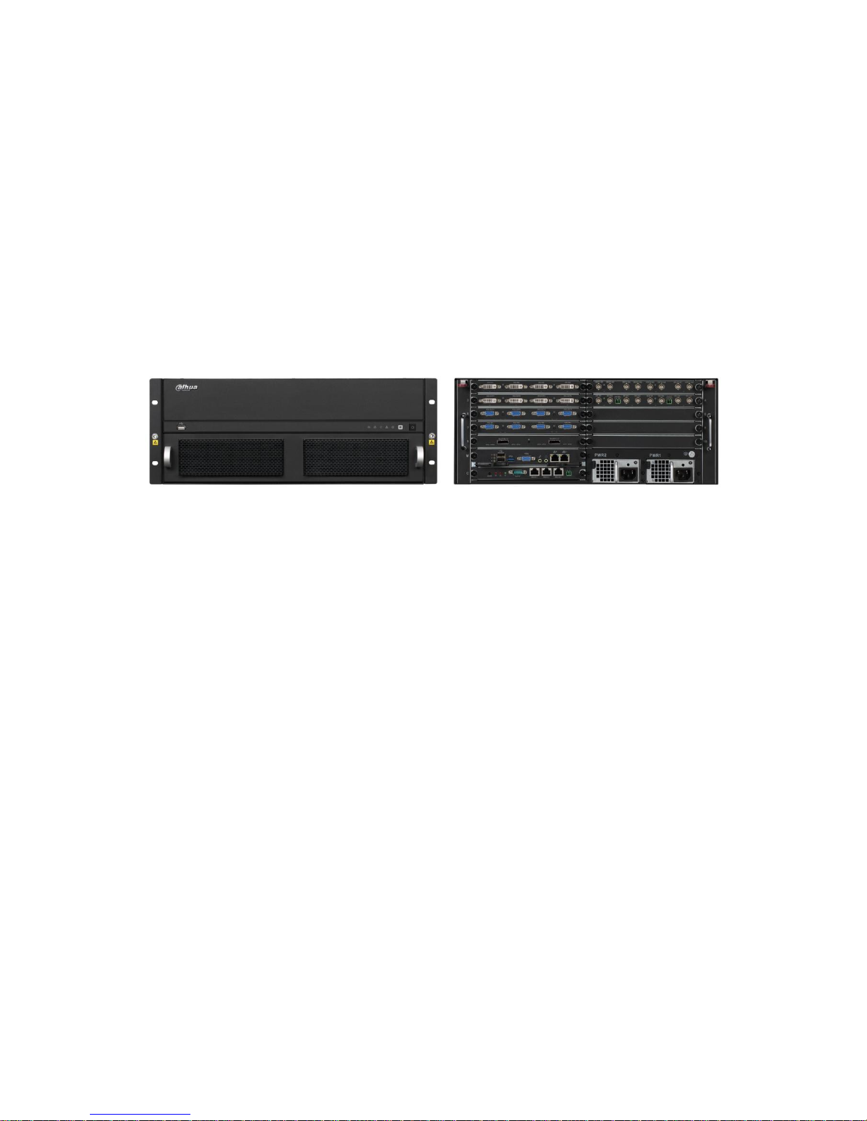
Figure 1- 1
1.2 Features
This product is a digital video matrix system with functions of digital video switch, multiple
operation insertion, centralized management, and distributed deployment. It achieves switches
among analog signal, digital signal, HD network signal and HD digital video signal and making
HD image available on video walls. It is a platform product integrating video signal
encoding/decoding, centralized data storage, online real-time preview and various networks, preplan, log, user authority management, device maintenance functions and etc., which allows HD
video command/dispatch and video conference.
1.2.1 Structure
19 inch 4U standard rack case for universal uses.
Card-type large scale ATCA structure for simple extension and flexibility.
2 groups of fans for intelligent temperature controlling, contributing to stabilized air passage
with the case structure to balance internal temperature.
Dual-channel redundant power supply for continuous working of device and security of data.
Double blade Function Card.
1.2.2 Hardware
Page 7

2
Intel x 86 Platforms for device expandability and fluency when system is in full load.
High speed connector on compression card, x4 PCI-E gen2,12V DC power supply, for
fluency of high speed data flow.
Compression card’s hot swap button and indicator for users’ flexible extension on the
application and knowledge of compression card status.
Various interfaces of compression card, such as USB, serial, Internet port, HDMI, BNC, DVI
and etc. which guarantee device functions and simplify operation and adjustment done by
users and technical staffs.
Each Function Card works independently to balance system’s work load and ensure fluency.
Duel-high-speed non blocking design for rear panel to meet demand of large volume A/V
data transmission.
1.2.3 Software
Embedded LINUX OS: safe, stable, efficient, and easy for development and maintenance.
Video Encoding/Decoding
Each A/V encode card can support 32-ch of BNC or 8-ch of HD-SDI, 4-ch of DVI (supports
DVI, VGA, HDMI signal) and 8-ch of HDCVI.
Each A/V decode card can support 64-ch of D1 or 16-ch HD1080P decoding output.
Network Function
2 RJ45 interfaces, supporting 1000M network.
Support TCP/IP protocol including TCP,UDP,RTP,RTSP, PPPoE,DHCP,DNS,
DDNS,NTP,SADP,SMTP,ISCSI and etc.
Support NAS, IP SAN network centralized storage, and support receiving system log
remotely.
Support management software to achieve remotely switching between analog and digital
videos on video wall and control with keyboard.
Support remotely receiving and configuring parameter, remotely rebooting and remotely
inputting/outputting parameters.
Video Management
Support HD, SD digital matrix, and direct switch as non-compression bit stream which
eliminate image quality reduction after multiple switches of video signal.
Support HD, SD network IPC matrix.
Support digital video full crossing switch matrix, based on different applied compression card
combination, forming different digital video full crossing switch matrix with different
specifications.
A/V decode card supports HDMI, DVI, VGA and BNC interfaces support up to
1080P(1920*1080P) resolution output.
Allow operator to loop display different images on same screen, pre-set and switch as group.
Page 8

3
Splicing image favorites, simplified operations on multiple video channels.
Other
Complete set of operation, alarm, abnormality and log recording, simplifying user and
technical staff’s maintenance.
Complete user authority management and storage management, while the authority can be
subdivided into a channel and a single HDD, making the device more user-friendly.
Support local and remote update, guaranteeing update to catch changing market demand.
Support network storage to accommodate demand from medium to large monitoring
systems.
Multiple users and clients login, convenient for users to preview and manage monitoring
whenever and wherever possible.
1.3 Introduction to Compression Cards in System
No.
Name
Model
Functional
Module
Description
Note
1
Platform
Host
Video Matrix
Platform-4U
Video matrix
platform host
1) 1 4U host,support 10
Function Cards
2)1 MBC0004 main
control panel
3)1 control panel
4)1 built-in power
adaptor (redundant)
Standard
(dualredundant
power
optional)
2
Input
Module
VEC0804HSM70
HD-SDI video
encoding card
1)8-ch HD-SDI video
input (BNC)
2)2-ch RS485 interface
Optional
VEC0404HDM70
HD DVI video
encoding card
4-ch DVI video input
Optional
(support
DVI, VGA,
HDMI)
VEC0804HCM70
HDCVI
encoding card
8-ch BNC video input
(HDCVI)
Optional
VEC0404HVM70
HD VGA
encoding card
4-ch VGA video input
Optional
3
Output
Module
VDC0404DM70
HD DVI
decoding card
4-ch DVI video output
port
Optional
VDC0404VM70
HD VGA
decoding card
4-ch VGA video output
port
Optional
4
RAID
Card
VS0201R-M70
RAID card
2-ch MINI, SAS port,
may connect to external
disk matrix
Optional
1.4 Host System
1.4.1 4U Host
Video matrix platform with 19 inch 4U structure host includes Function Card slot, power interface
and intelligent temperature-controlled fan. For product appearance, please see Figure 1- 2.
Page 9
4
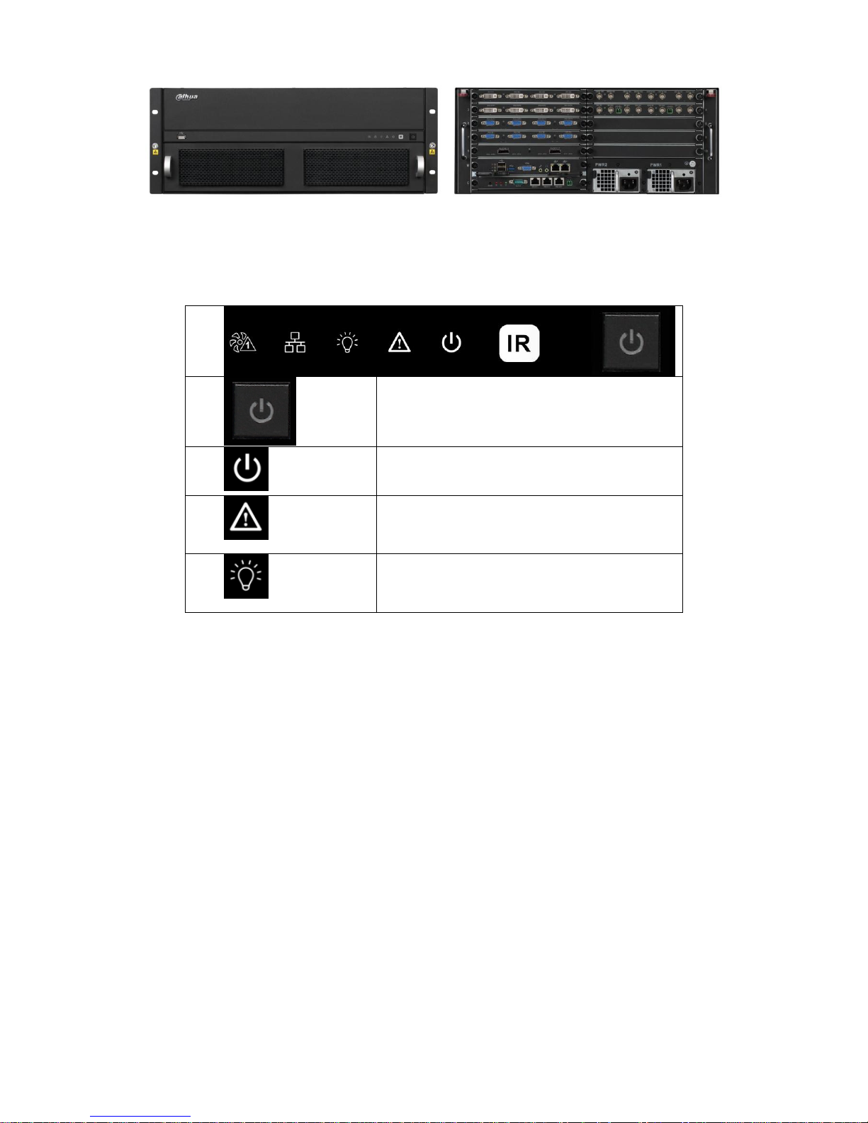
Figure 1- 2
Front panel, for displaying device working status;
ON/OFF button.
Device power indicator.
Off: Not operating after plugged in.
Red: Operating.
Device alarm indicator.
Red: Alarm on.
Off: Alarm off.
Device tatus indicator.
Yellow: Device is properly running.
Air intake of host with dust filter at rear;
Intelligent temperature-controlled fan, total of 2 groups, allow hot swap;
Function Card’s rear interface board slot, total of 10, labeled in sequence, for installation of
Function Card’s rear interface board;
Main control panel’s rear slot, marked as “M”;
Control panel’s rear slot, marked as “C”.
Duel-power module, support 220V modules.
1.4.2 Main Control Panel
1.4.2.1 Interface Introduction
Please see Figure 1- 3.
Page 10

5
Figure 1- 3
No.
Interface
Function
1
Reset Button
1, support restoring to default settings
2
Mainboard
Power Indicator
1, display mainboard power status
System Status
Indicator
1, display system working status
PCI-E Status
Indicator
1, display PCI-E working status
3
USB Port
3, as 1 USB 3.0 and 2 USB 2.0 for connection to mouse,
keyboard, USB
4
VGA
1, for local display output
5
Audio Input
1, for audio bidirectional talk
6
Audio Output
1, for audio bidirectional talk
7
Kilomega RJ45
Port
2, for transmission of network A/V data and network control
signal.
1.4.2.2 Features
High speed connector, including 10 x4 PCI-E gen2, 12V DC power, IIC
Memory slot, 1 single channel, 4G DDR3L memory
Fan interface, power/rotation rate control (CPU)
3 indicators (power indicator, system running status indicator, PCI-E status indicator)
1.4.3 Control Panel
1.4.3.1 Interface Introduction
Please see Figure 1- 4.
Figure 1- 4
No.
Interface
Function
1
Clear Alarm
1, support to clear alarm
Page 11
6
Button
2
Mainboard
Power Indicator
1, display mainboard power status
3
Alarm Indicator
1, display alarm status
4
System Status
Indicator
1, display system working status
5
RS232
1, DB9, debug serial or central control serial
6
RJ45 Port
3, for control of peripheral equipment
7
RS485
1
1.4.3.2 Features
Control device power up/down and working status monitoring
When system has alarm, via alarm clear button to clear alarm of the system
3 indicators (power indicator, system running status indicator, system alarm indicator)
Via RS232 serial connection with central control device or debug PC
Via RJ45 serial control peripheral equipment, such as analog matrix, wall and etc.
1.5 Function Card
Function Card adopts blade module design, and is mainly used to input analog, digital video and
centralize encoding compression, achieving remote preview, network centralized storage and etc.
1.5.1 VEC0404HD-M70 Video Matrix Platform 4-CH HD DVI
Encoding Card
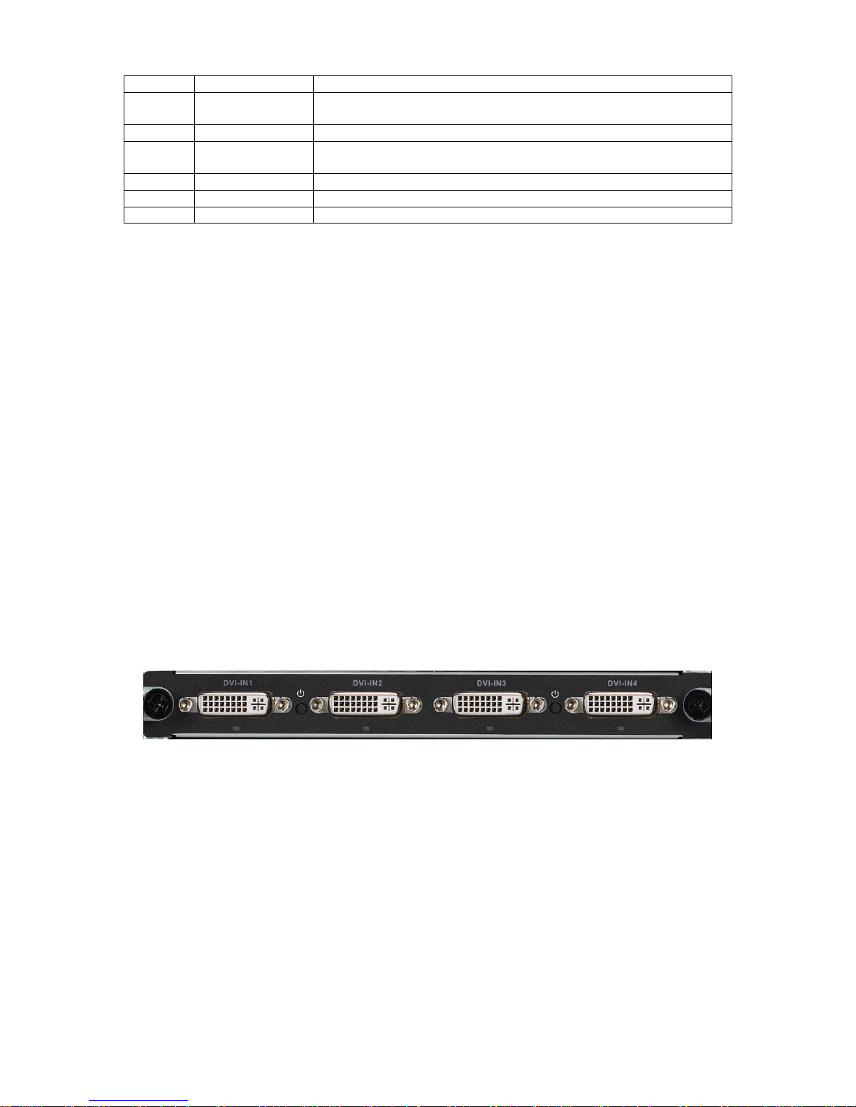
Please see Figure 1- 5.
.
Figure 1- 5
1.5.1.1 Main Features and Performance
Features
4-ch DVI-I video interface input, supporting HDMI, VGA and DVI input
2 buttons, hot swap
4 indicators
High speed connector, including x4 PCI-E gen2,12V DC power
Encoding Function
Page 12

7
Support DVI HD input port: 1080P@60Hz, 1680*1050@60Hz, 1440*900@60Hz,
1366*768@60Hz, 1280*1024@60Hz, 1280*960@60Hz, 1280*800@60Hz, 1280*720@60Hz,
1152*864@60Hz, 1024*768@60Hz, 800*600@60Hz
Adopt H.264 video compression technology
Video encoding parameter is adjustable in each channel, including resolution, bit stream rate,
image quality and etc.
Each channel supports schedule and event as compression parameters
Support composite and bit stream encoding.
Support dual stream technology
Support picture compression in 4 CIF under JPEG standard or CIF and net transmission
Support watermark technology
1.5.1.2 Interface introduction
VIN video input interface, DVI-I interface
1.5.1.3 Technical Specifications
Model
VEC0404HD-M70
A/V Input
Video Input
4-ch, DVI-I
A/V
Encoding
Parameter
Video
Compression
Standard
H.264
Video
Encoding
Resolution
1080P, 1680*1050, 1440*900, 1366*768, 1280*1024,
1280*960, 1280*800, 1280*720, 1152*864, 1024*768, 800*600
Video Frame
PAL:1/16--25 frame/s, NTSC: 1/16--30 frame/s
Bit stream Rate
48Kbps-2048Kbps,customizable, max 4096Kbps
Dual Stream
Support
1.5.2 VEC0404HV-M70Video Matrix Platform 4-CH VGA
Encoding Card
Please see Figure 1- 6.
Figure 1- 6
1.5.2.1 Main Features and Performance
Features
4-ch VGA video interface input, support VGA signal input
2 buttons, hot swap
Page 13

8
4 indicators
High speed connector, including x4 PCI-E gen2,12V DC power
Encoding Function
VGA HD input port: UXGA@60Hz
1080P@60Hz,1080P@50Hz,720P@50Hz,720P@60Hz,1024x768@60Hz,1024x768@75Hz
,1280x1024@60Hz,1280x1024@75Hz;
Adopts H.264 video compression technology
Video encoding parameter is adjustable in each channel, including resolution, bit stream rate,
image quality and etc.
Each channel supports schedule and event as compression parameters
Support composite and bit stream encoding.
Support dual stream technology
Support picture compression in 4 CIF under JPEG standard or CIF and net transmission
Support watermark technology
1.5.2.2 Interface introduction
VIN video input interface, VGA interface
1.5.2.3 Technical Specifications
Model
VEC0404HV-M70
A/V Input
Video Input
4-ch, VGA
A/V
Encoding
Parameter
Video
Compression
Standard
H.264
Video
Encoding
Resolution
UXGA@60Hz,1080P@60Hz,1080P@50Hz,
720P@50Hz,720P@60Hz,1024x768@60Hz,
1024x768@75Hz,1280x1024@60Hz,1280x1024@75Hz;
Video Frame
PAL:1/16--25 frame/s, NTSC: 1/16--30 frame/s
Bit stream Rate
48Kbps-2048Kbps,customizable, max 4096Kbps
Dual Stream
Support
1.5.3 VEC0804HS-M70 Video Matrix Platform 8-CH HD SDI
Encoding Card
Please see Figure 1- 7.
Figure 1- 7
Page 14

9
1.5.3.1 Main Features and Performance
Features
8-ch HD-SDI video interface input
2-ch RS485 interface
2 buttons, hot swap
4 indicators
High speed connector, including x8 PCI-E gen2, 12V DC power
Encoding Function
Adopts H.264 video compression technology
Video encoding parameter is independently adjustable in each channel, including resolution,
frame rate, bit stream rate, image quality and etc.
Each channel supports schedule and event as compression parameters
Support composite and bit stream encoding, A/V are synchronized in composite.
Support dual stream technology
Support picture compression in 4 CIF under JPEG standard or CIF and net transmission
Support watermark technology
1.5.3.2 Interface Introduction
VIN video input interface, BNC interface
1.5.3.3 Technical Specifications
Model
VEC0804HS-M70
A/V Input
Video Input
8-ch SDI (BNC) (electrical level: 1.0Vp-p; impedance: 75Ω)
A/V
Encoding
Parameter
Video
Compression
Standard
H.264
Video
Encoding
Resolution
1080P/720P/D1/HD1/2CIF/CIF/QCIF
Video Frame
PAL:1/16--25 frame/s, NTSC: 1/16--30 frame/s
Bit stream Rate
48Kbps-4096Kbps,customizable, max 8192 Kbps
Dual Stream
Support
1.5.4 VEC0804HC-M70 Video Matrix Platform 8-CH HDCVI
Encoding Card
Please see Figure 1- 8.
Figure 1- 8
Page 15

10
1.5.4.1 Main Features and Performance
Features
8-ch BNC video input interface, support HDCVI signal input.
8-ch audio input, support external and built-in.
Countercharge
2 buttons, hot swap
4 indicators
High speed connector, including x4 PCI-E gen2, 12V DC power
Encoding Function
HDCVI HD input port 1080P@30Hz, 1080P@25Hz, 720P@60Hz, 720P@50Hz,
720P@30Hz, 720P@25Hz
Adopts H.264 video compression technology
Adopts G711a, PCM and G711u audio compression standard
Video encoding parameter is independently adjustable in each channel, including resolution,
frame rate, bit stream rate, image quality and etc.
Each channel supports schedule and event as compression parameters
Support composite and bit stream encoding, A/V are synchronized in composite.
Support dual stream technology
Support picture compression in 4 CIF under JPEG standard or CIF and net transmission
Support watermark technology
1.5.4.2 Interface Introduction
A/V input interface, BNC interface
1.5.4.3 Technical Specifications
Model
VEC804HC-M70
A/V Input
Video Input
8-ch BNC
Audio Input
8-ch HDCVI built-in
A/V
Encoding
Parameter
Video
Compression
Standard
H.264
Video
Encoding
Resolution
1080P/720P
Video Frame
PAL:1/16--25 frame/s, NTSC: 1/16--30 frame/s
Bit stream Rate
48Kbps-2048Kbps,customizable, max 4096 Kbps
Dual Stream
Support
Audio
Compresson
Standard
G711a, PCM, G711u
Audio Stream
Rate
8K16BIT
Page 16

11
1.5.5 VDC0404D-M70 Video Matrix Platform 4-CH HD DVI
Decoding Card
Please see Figure 1- 9.
Figure 1- 9
1.5.5.1 Main Features and Performance
Features
4-ch DVI digital video interface output
2 buttons, hot swap
4 indicators
High speed connector, including x4 PCI-E gen2, 12V DC power
Decoding Function
Support 64-ch D1 or 16-ch 1080p decoding output
Support 16-ch D1 uncompressed data output
Support DVI output interface 1080p@50/60Hz, 1280*720@50/60Hz, 1024*768@60Hz
Support hot swap
1.5.5.2 Interface Introduction
VOUT video output port, DVI port
1.5.5.3 Technical Specifications
Model
VDC0404D-M70
A/V Output
Video Output
4-ch DVI digital video port output
A/V
Decoding
Parameter
Video
Compression
Standard
H.264, MPEG4
Video
Decoding
Resolution
1920x1080/1280x1024/1280x720/1024x768
Video
Processing
Capacity
Support 64-ch 4CIF/24-ch HD 720P/16-ch HD 1080P image
decoding output; support 16-ch 4CIF or 4-ch HD original data
stream direct output
Bit stream Rate
48Kbps-4096Kbps,customizable, max 8192 Kbps
Image Display
Method
1, 4, 8,9,16 screen split
1.5.6 VDC0404V-M70 Video Matrix Platform HD VGA
Decoding Card
Page 17

12
Please see Figure 1- 10.
Figure 1- 10
1.5.6.1 Main Features and Performance
Features
4-ch VGA digital video interface output
2 buttons, hot swap
4 indicators
High speed connector, including x4 PCI-E gen2, 12V DC power,
Decoding Function
Support 64-ch D1 or 16-ch 1080p decoding output
Support 16-ch D1 uncompressed data output
Support VGA output interface 1080p@50/60Hz, 1280*720@50/60Hz, 1024*768@60Hz
Support hot swap
1.5.6.2 Interface Introduction
VOUT video output port, VGA port
1.5.6.3 Technical Specifications
Model
VDC0404V-M70
A/V Output
Video Output
4-ch VGA digital video port output
A/V
Decoding
Parameter
Video
Compression
Standard
H.264, MPEG4
Video
Decoding
Resolution
1920x1080/1280x1024/1280x720/1024x768
Video
Processing
Capacity
Support 64-ch 4CIF/24-ch HD 720P/16-ch HD 1080P image
decoding output; support 16-ch 4CIF or 4-ch HD original data
stream direct output
Bit stream Rate
48Kbps-4096Kbps,customizable, max 8192 Kbps
Image Display
Method
1, 4, 8,9,16 screen split
1.5.7 VS0201R-M70 Video Matrix Platform M70 Series RAID
Card
Please see Figure 1- 11.
Page 18

13
Figure 1- 11
1.5.7.1 Main Features and Performance
Features
2 MINI SAS ports, may connect to external disk matrix
1 button, hot swap
8indicators (MINI SAS work indicator)
High speed connector, including x4 PCI-E gen2, 12V DC power
Storage Function
Support raid0, raid1, raid5, raid6, raid10
Support two disk racks or up to 48 HDDs
Support max rate 6Gbps of each SAS port
Support 152-ch 1080P storage capacity
Data protection supports battery protection Cache
Support global hot spare
Support disk group management
1.5.7.2 Interface Introduction
MINI SAS port
1.5.7.3 Technical Specifications
Model
VS0201R-M70
Storage
Parameter
External Port
MINI SAS *2
RAID Mode
Raid0, raid1, raid5, raid6, raid10
Disk Rack
Support two disk racks
HDD
Max support 48 HDD
Port Rate
Each SAS port max rate is 6Gbps
Page 19

14
2 Open-Package Inspection and Wiring
2.1 Inspection Procedure
When you receive video matrix platform, please check for obvious external damage. The material
of product package should be able to protect the product from majority impacts during
transportation.
Secondly please open the package, and check all accessories see if any part is missing. You
may refer to accompanied accessory bag. After you have checked that all parts are included, you
may remove protector on device.
Thirdly, please open device case to check front panel’s wiring, power line and see if the
connection between mainboard and interface board is loose.
2.2 Accompanied Assessory Bag
Accompanied assessory bag includes user’s manual and disk. When you unpackage the product,
please make sure all contents match the checklist.
2.3 Device Installation
At time of inserting mainboard and Function Card into chassis, please remove the protection
cover at connection interface of real panel.
In case of beep, it may be that either one of power modules is not well fixed. You may press
the small red button next to power module at the rear of device to cancel beep alarm.
Page 20

15
3 Local Interface Config
3.1 Software Interface Basic Operation
3.1.1 Boot Up Device
Plug in power line, and press power switch on front panel. Power indicator turns on and device
boots up followed by boot interface which lasts for 90s.
When you boot up device, please keep the following in mind:
1) Make sure whether the supplied voltage is within 100~240V 47~63Hz. Turn on the device
after you check power line connection.
2) We recommend you to use power supply with stable voltage and little interference (refer to
international standard), which benefit the device to work stably and last longer. This will also
benefit external devices such as camera. UPS is the best choice if possible.
3.1.2 Shut Down Device
1. Enter main menu in shutdown system select shutdown device.
2. Press ON button on panel for 5s to shutdown.
Note:
Method 1 is recommended.
Stop all performance of the device, and then you may unplug the device from power
supply.
3.1.2.1 Outage Recovery
When the device is under working status, and there is an outage or forced shutdown, the
system can automatically save and resume previous working status after power recovery.
3.1.2.2 Replace Button Battery
Please make sure to use the same battery model if possible.
We recommend replace battery regularly (such as one-year) to guarantee system time
accuracy.
Note: Before replacement, please save the system setting, otherwise, you may lose the
data completely!
3.1.2.3
3.1.3 Enter System Menu
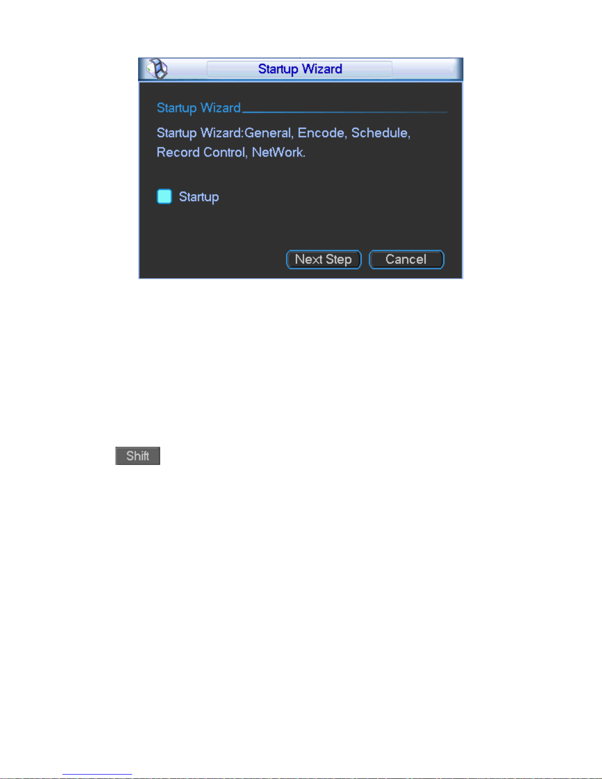
After you properly turn on the device, system pops up the startup wizard. Click the Cancel button;
you can go to the system login interface. Click the Next Step button; you can go to the startup
wizard interface. Here you can set general, encode, schedule, record control, and network.
Please see Figure 3- 1.
Page 21
16
Figure 3- 1
The system login interface is shown as in Figure 3- 2.
System consists of four accounts (defaulted):
Username: admin. Password: admin. (administrator, local and network)
Username: 888888. Password: 888888. (administrator, local only)
Username: 666666. Passwords: 666666(Lower authority user who can only monitor, playback,
backup and etc.)
Username: default. Password: default(hidden user)
You can use USB mouse, front panel, remote control or keyboard to input. About input method:
Click to switch between numeral, English character (small/capitalized) and denotation
and click designated buttons on soft keyboard with the mouse.
Note:
For security reason, please modify password after you first login. To add user group, user
and edit user please refer to User Account Section.
Within 30 minutes, three times login failure will result in system alarm and five times login failure
will result in account lock!
Page 22

17
Figure 3- 2
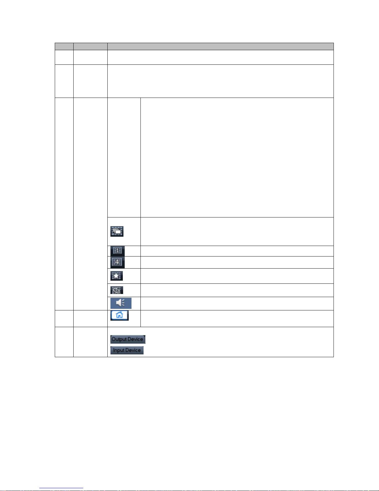
3.1.4 Main Interface Introduction
After you logged in, you will enter main interface as shown in Figure 3- 3 (for various icon
definitions, please refer to the following Chart 3- 1).
Figure 3- 3
1
2
3
4
5
Page 23
18
No.
Name
Function Description
1
Current
Output
Display current output slot name
2
Display
window
Display current output screen or cubeless video wall’s splicing illustration.
Click channel, and if its corresponding area turns yellow, it is selected
successfully.
Support1, 4, 8, 9, 16 channel display at the same time.
3
Display
Control
Area
Display
mode
selection
area
Display mode:single channel, 4-ch, 8-ch, 9-ch and 16-ch available.
(device differ for different number of channels)
Under single channel mode, you may select 1st to 16th channel.
Under 4-ch mode, you may switch among :
1st to 4th channel
5th to 8th channel
9th to 12th channel
13th to 16th channel
Under 6-ch mode, you may switch between 1st to 6th channel and 7th
to 12th channel, and 13th to 18th channel.
Under 8-ch mode, you may switch between 1st to 8th channel and 9th
to 16th channel.
Under 9-ch mode, you may switch between 1st to 9th channel and 8th
to 16th channel.
Under 16-ch mode, you may view full 16 channels at the same time
Independent display button. It allows an independent view of any
window selected in a single screen or independent view plus
crossing screen function in a cubeless video wall. To exit, you need
to re-split and drag selected window.
May split all cubeless video wall units into one.
May split all cubeless video wall units into four.
Favorites,you may save combination of display channels which you
often monitor.
Tour button,support tour decoding and wall mount.
Sound on/off.
4
Shortcut
Menu
Click to enter homepage.
5
Input and
Output
Device
Show input and output devices of each slot and channel
Click this button to switch to output device list.
Click this button to switch to input device list.
Chart 3- 1
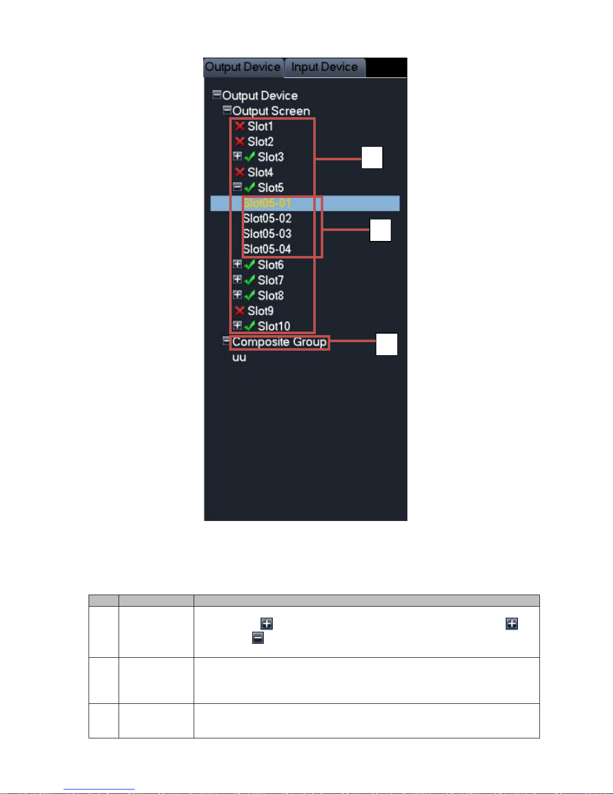
3.1.5 Output Device Tree Introduction
The output device tree is show as follows; please see Figure 3- 4 and Chart 3- 2.
Page 24
19
Figure 3- 4
No.
Name
Function Description
1
Output Card
List Area
List of output card inserted in slot, when an output card is inserted into
current slot, will display. You may click it to extend the list as will
change to . Meanwhile the current output card’s corresponding output
interface name will be listed.
2
Output
Interface List
Area
Display all output interface names under current output card. You may
switch display control area to current output interface by double clicking on
output interface name to achieve control over displayed contents of current
output interface.
3
Cubeless
video wall List
Area
Display current cubeless video wall list. You may double click cubeless
video wall to switch from display control area to current cubeless video wall
to achieve control over displayed contents of current cubeless video wall.
1
2
3
Page 25
20
Chart 3- 2
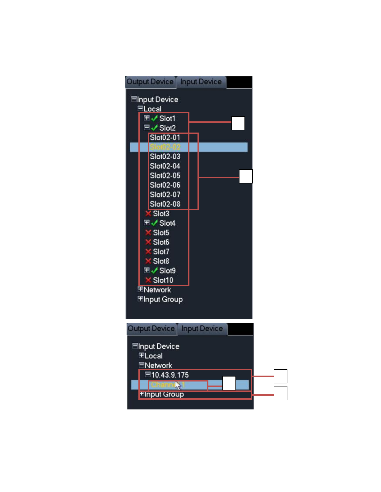
3.1.6 Input Device Tree Introduction
The input device tree is show as follows; please see Figure 3- 5 and Chart 3- 3.
Figure 3- 5
1 2 3 4 5
Page 26
21
Chart 3- 3
3.1.7 Display Control Area Introduction
The display control area is shown as follows; please see Figure 3- 6 and Chart 3- 4.
Figure 3- 6
No.
Name
Function Description
1
Decoding
Card List Area
List of Decoding Card inserted in slot, when an Decoding Card is inserted
into current slot, will display. You may click it to extend the list as will
change to . Meanwhile the current Decoding Card’s corresponding input
interface name will be listed.
2
Input Interface
List Area
Display all input interface names under current Decoding Card. After control
area displays, select channel. By double clicking input interface name, you
may switch from local input channel to currently selected input channel.
3
Remote Input
List Area
Display added remote device list, and devices may be DVR, IPC and
otherencoding devices. It will display icon, and you may click it to
extend the list as . Meanwhile channels supported by current remote
device will be listed.
4
Remote Input
Channel List
Area
Display all input channel names under surrent remote device. After control
area displays, select channel. By double click input interface name, you
switch from remote input channel to currently selected input channel.
5
Input Group
When there is input group, it will display icon and you may click it to
extend the list as . Current input group name will be displayed.
1 2 3
Page 27
22
Chart 3- 4
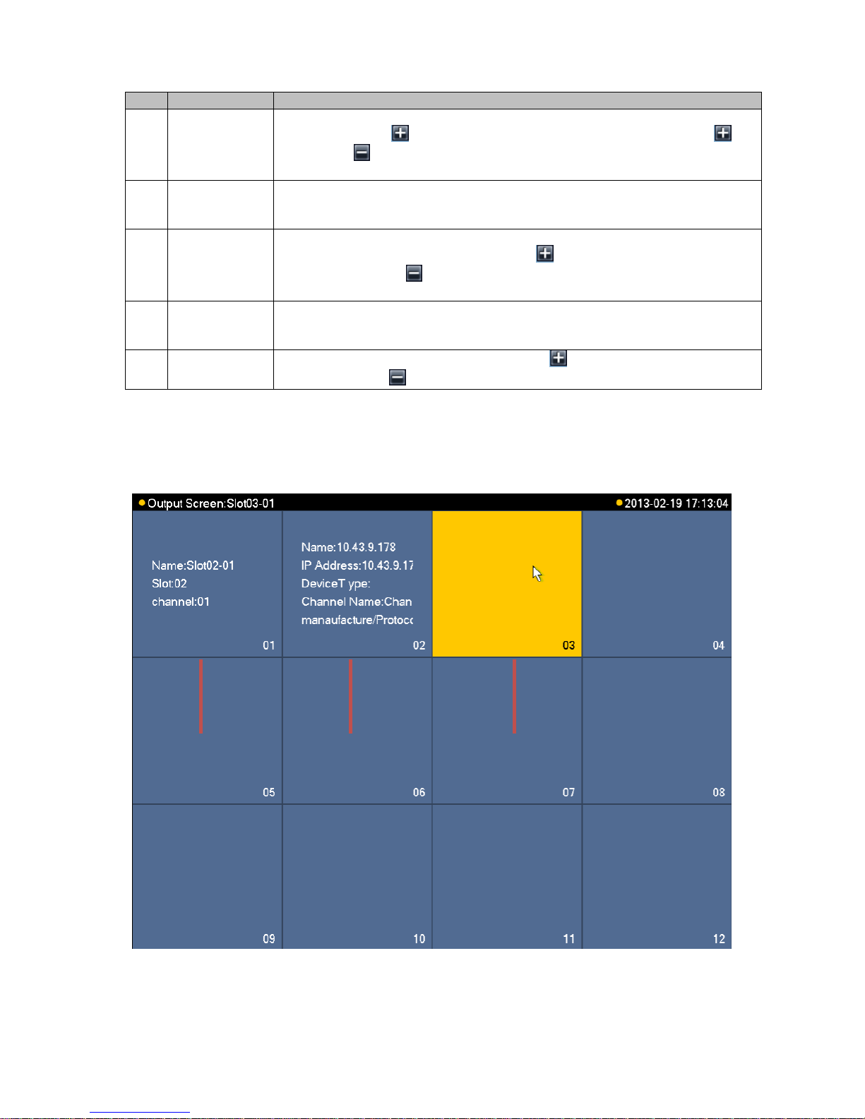
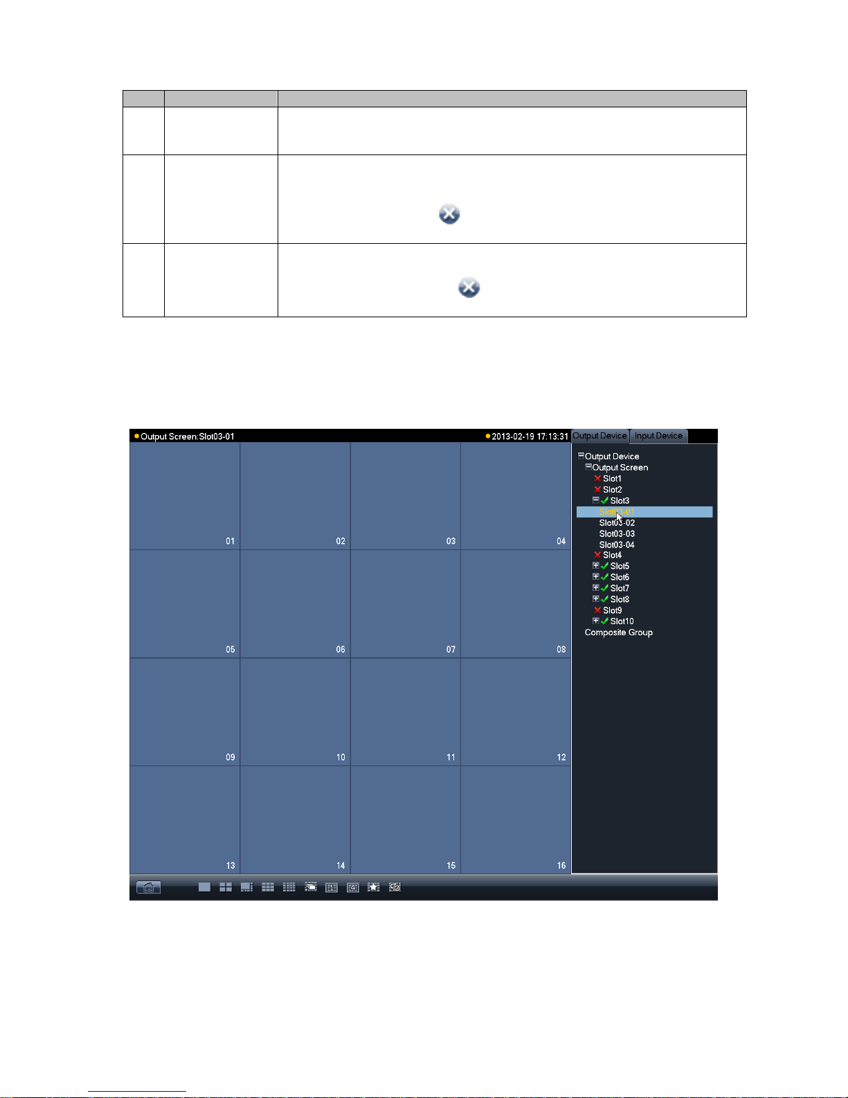
3.1.8 Display Setting
Video Matrix has no output by default after first boot up. You may set it on main menu.
Figure 3- 7
In output list, click output channel name to select designated split window. Please see Figure 3- 7.
No.
Name
Function Description
1
Blank Area
When current output interface’s current output channel does not have
corresponding input channel, the status info is blank. You may click this
channel to view it, and its corresponding area will turn yellow.
2
Remote Input
Display
If current output interface’s output channel has been set up remote input
device device channel, then device ID, IP address, device type, channel
name, manufacturing protocol will be displayed. When you click this
channel, you will see icon which allow you to close displayed
contents in this channel.
3
Local Input
Display
If current output interface’s output channel has been set up local input
device channel, then name, slot, channel will be displayed. When you click
this channel, you will see icon which allow you to close displayed
contents in this channel.
Page 28
23
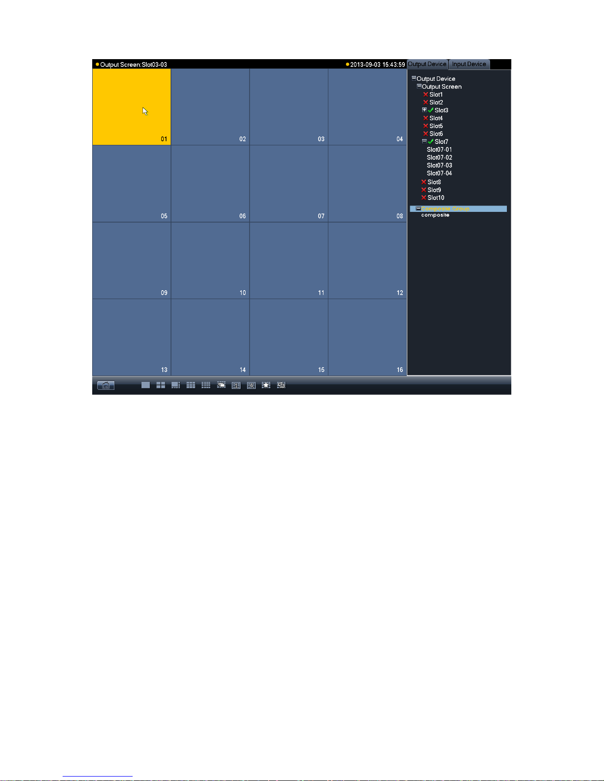
Figure 3- 8
In display window, select corresponding channel and then its corresponding window turns yellow.
Please see Figure 3- 8.
Page 29
24
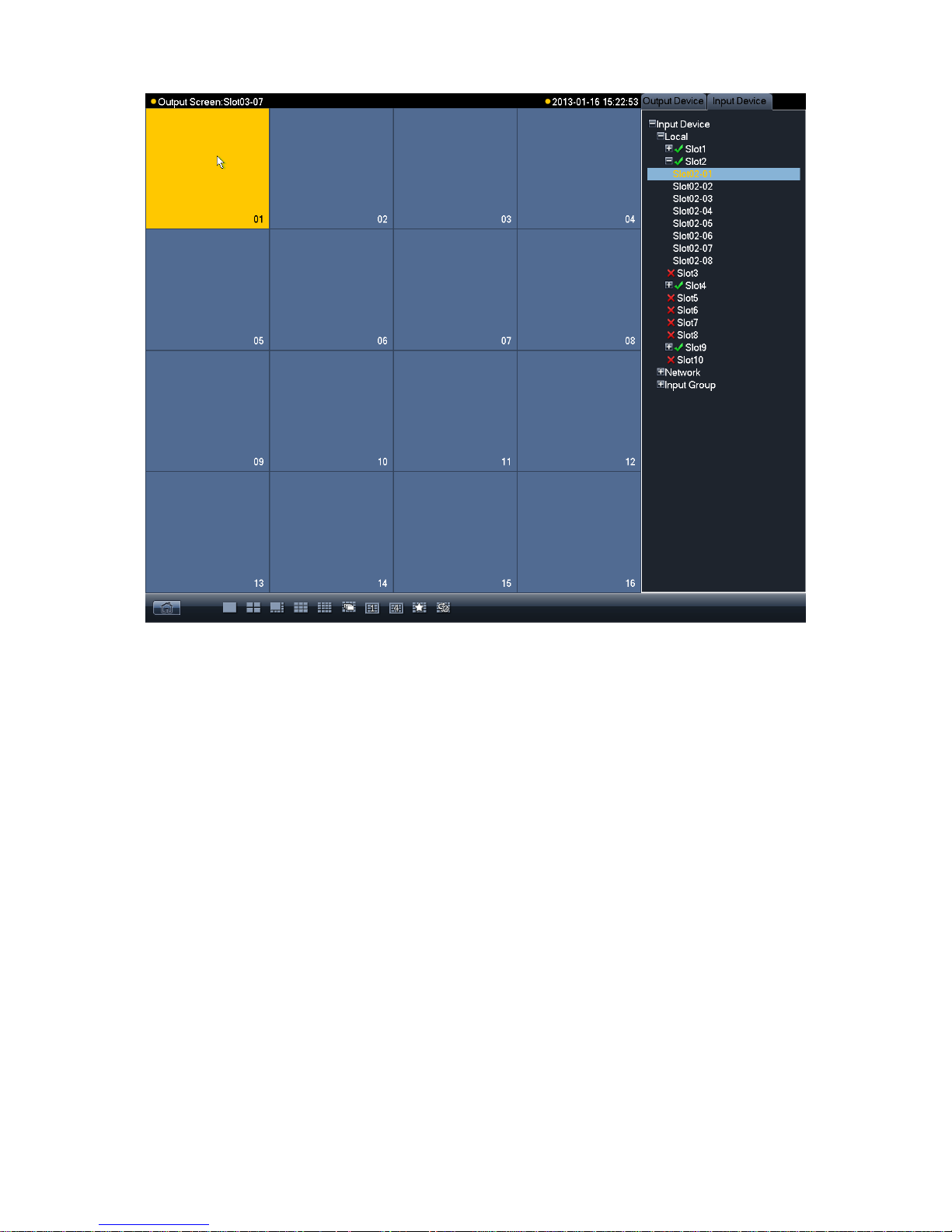
Figure 3- 9
Switch to input device list. Please see Figure 3- 9.
Page 30
25
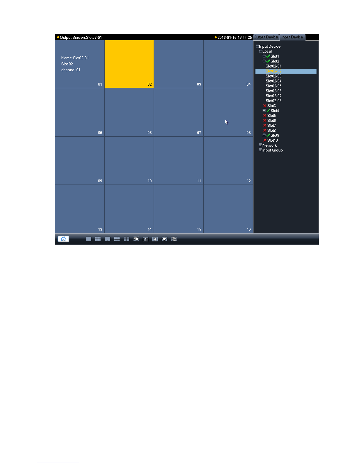
Figure 3- 10
Double click corresponding input channel and then you may config video to output interface.
Please see Figure 3- 10.
Double click homepage, you will see Figure 3- 11.
Page 31

26
Figure 3- 11
E-zoom: When input device supports e-zoom, you can use this function.
Close Video: Delete current output screen’s channel configuration.
Cubeless: Cubeless video wall.
Input Group: Config input group. You can display all video config of input group on the
output screen. When signal of input is more than the max split of output screen, auto tour
starts.
Scheme: Config scheme. Save all output screen config of current device.
Main Menu: Display main menu.
Shutdown: Shutdown device.
The following sections are descriptions of input group and scheme. For other functions, please
refer to later chapters.
3.1.9 Input Group
Step 1. Click input group and you will enter Figure 3-13.
Page 32

27
Figure 3- 12
Step 2. Click add. You will see Figure 3- 13.
Figure 3- 13
Page 33

28
Step 3. Select input source. means selected. Click add, and fill in name of input group. Click
OK. See Figure 3-15 and Figure 3-16.
Figure 3- 14
Page 34

29
Figure 3- 15
Step 4. You may continue adding if you need. If you want to delete input group, you can check
the small box in front of designated group and click delete. Click OK to confirm. When
you are done, click OK to exit. You can open the input group you added in Figure 3-17.
Page 35

30
Figure 3- 16
Step 5. In output device list, double click output channel name and select one output channel.
You will see its corresponding window turns yellow. Please see Figure 3- 17.
Page 36

31
Figure 3- 17
Step 6. Switch to input device list. Double click configured input group, you will see configured
signal source appear on output channel. See Figure 3-19.
Page 37

32
Figure 3- 18
Note:
When signal of input is more than the max split of output screen, auto tour starts.
3.1.10 Scheme
Step 1. Click scheme, and you will enter Figure 3- 19.
Page 38

33
Figure 3- 19
Step 2. Click add to add new scheme. See Figure 3- 20.
Figure 3- 20
Step 3. If the name has already existed, you may rename it. See Figure 3- 21.
Page 39

34
Figure 3- 21
Step 4. You may delete and load existing scheme.
Note: If the scheme is not configured, you cannot save it.
3.2 Advanced Menu Operation
3.2.1 Menu Navigation
Main
Menu
1st Level
Submenu
Option Note
Info
HDD Info
SATA interface status, HDD total capacity, free space, video
start/end time and etc.
BPS
Wave pattern means that calculation of each channel’s current
bit stream size and used capacity per hour.
Log
It displays system log for important event. You may appoint log
for event requires recording.
Version
It displays system hardware features, software version, release
date and etc.
Online User
To view online user info.
Status
To view fan speed, card information and its temperature info,
source info, net percentage, CPU percentage and memory
percentage.
Setting
General
It includes system time, video record saving method, local
device No. and etc.
Page 40

35
Encode
AV encoding mode, frame rate, quality and other parameter
setting
Schedule
It includes timing setting for general video record, motion detect
and external alarm.
RS232
To set serial function, baud rate and other parameters.
Network
To set network address, video data transmission protocol and
other parameters and PPPoE, DDNS function.
Detect
To set motion detect’ sensitivity, area and handling (alarm
output and boot up video record) parameter, video loss, black
screen detection and etc.
Pan/Tilt/Zoom
To set communication protocol, baud rate and other parameters
with PTZ device.
Display
Setting of menu output and monitoring tour parameter
Default
Choose to restore factory settings for all or partial configs
△Note:User accounts do not have recovery function.
Advanced
HDD Manage
HDD management, emptying HDD and etc.
△Note:If you edit HDD property, then you must reboot the
system to make change effective.
Abnormality
To set up alarm for abnomaly event such as no HDD, HDD
error.
Record
To boot up or shutdown channel schedule.
Account
To modify user group and user account.
Auto Maintain
To set up auto maintenance for item requires it.
Cubeless video
Wall
To config cubeless video wall output.
RAID
To config Raid for record storage.
Remote
Device
To add, delete remote devices.
Shutdown
To Log off menu user, shutdown system, reboot system and
switch user.
3.2.2 Menu Operation
After you logged in, the system main menu is shown as below. Please see Figure 3- 22.
There are total five icons: setting, advanced, remote device, info, and shutdown.
Note: 1. Setting in all submenus will come effective only after you click save,
otherwise you will lose all modified settings. 2. If a check box is filled with or
checked, then it is available in corresponding text; otherwise, it is not available in the
text.
Page 41

36
Figure 3- 22
3.2.3 Info
After you enter information menu, the submenu is shown as below. Please see Figure 3- 23.
There are total five icons: HDD info, bit per second (BPS), log, version, online user and status.
Figure 3- 23
3.2.3.1 HDD Info
Page 42

37
It displays HDD interface status, total capacity of all HDDs, free space, video record start and
end time, status and etc. Please see Figure 3- 24.
Figure 3- 24
In HDD info, add “*” after SN means is it current working disk (i.e. 1*). Status info shows whether
there is conflict in the disk. If disk is damaged, system shows as “?”.
After system booted up, if there is any conflict, system goes to HDD information interface directly.
Please note, system does not ask you to deal with it forcedly.
When HDD confliction occurs, you can check whether system time and HDD time are identical or
not. If they are not identical, please go to General to adjust system time or go to HDD
Management to format HDD and then reboot device. Please see Figure 3- 25.
Page 43

38
Figure 3- 25
Note: You may left click view recording times button to switch to view type and
capacity.
3.2.3.2 Log
The interface displays system log file.
Log types include system, config, storage, alarm, record, account, clear, and playback.
Pleased select start time and end time, then click search button. You can view the log files in list
format. System max displays 15 logs in one page. Please use page up/down button to turn
pages. Please see Figure 3- 26.
Page 44

39
Figure 3- 26
3.2.3.3 BPS
This interface real time displays bit stream (Kb/S) and used space (MB/H), while wave pattern
better shows changes in bit stream. Please see Figure 3- 27.
Figure 3- 27
Page 45

40
3.2.3.4 Version
The interface displays system version, WEB version and their SN. You may click start to upgrade
system after connect a USB device to device.
Note: The upgrading file in USB must be named update.bin.
3.2.3.5 Online Users
In this interface, you can view and management online users connected to device. You may also
disconnect or shield selected (with √ in box) users (for a set period up to 65535s). Please see
Figure 3- 28.
Figure 3- 28
3.2.3.6 Status
Please see Figure 3- 29.
Page 46

41
Figure 3- 29
Fan speed: It displays current speed of two fans.
Card information: It displays card information of each slot, including type, encoding/decoding.
It also displays current status of each card, including data exchange and online status.
Temperature Information: It displays current temperature and status of each card.
Source Information: It displays usage of two group of power.
Time: It displays current time.
Net percentage: It displays net sending and receiving percentage of each network port.
CPU percentage: It displays usage percentage of each CPU.
Memory percentage: It displays percentage of memory.
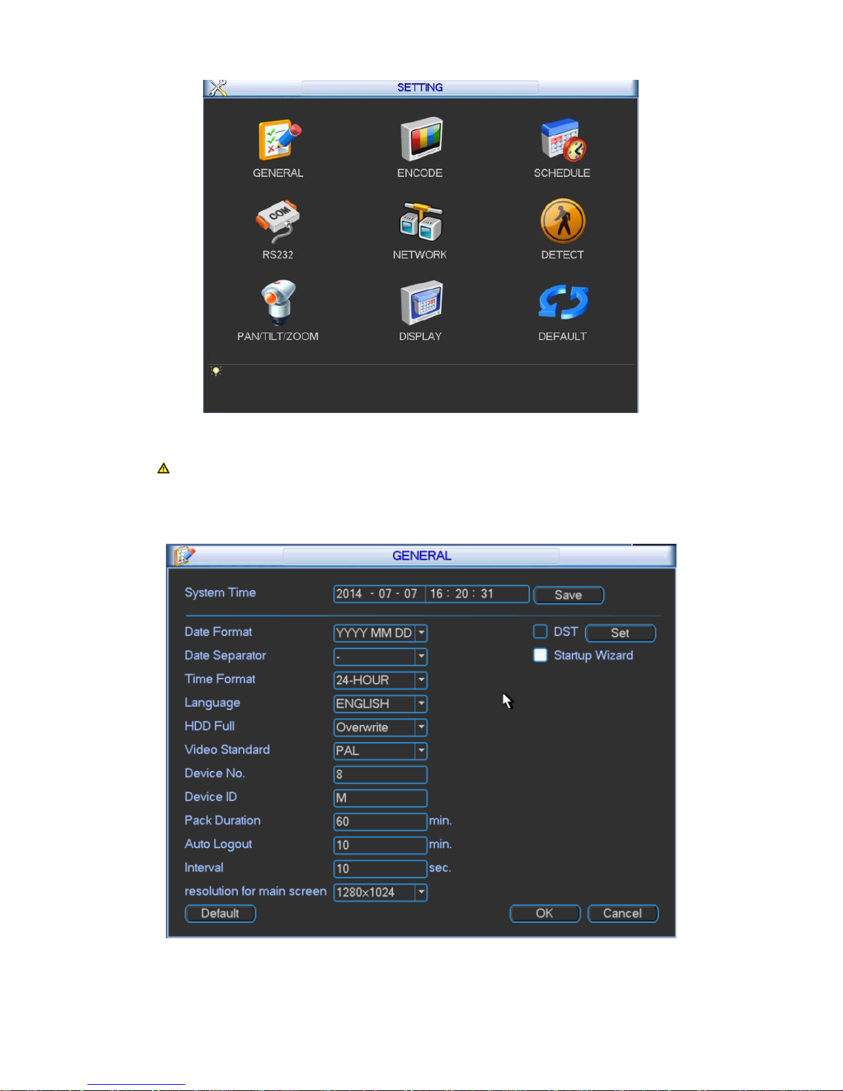
3.2.4 System Setting
System setting includes submenu: general, encode, schedule, RS232, network, detect,
pan/tilt/zoom (PTZ), display, and default. Please see Figure 3- 30.
Page 47
42
Figure 3- 30
Note: Only authorized user can enter system setting.
3.2.4.1 General
General setting interface is shown as follow; please see Figure 3- 31.
Figure 3- 31
Page 48
43
System time: You can set system date and time. After you modify setting, you must save
your change to make changes effective.
Date format: There are three types: YYYY-MM-DD: MM-DD-YYYY or DD-MM-YYYY.
Date separator: There are three denotations to separate date: dot, beeline and solidus.
Time format: There are two types: 24-hour mode or 12-hour mode.
Language: To switch menu language (as English and Simplified Chinese)
HDD full: You may select working mode when hard disk is full. There are two options: stop
recording or rewrite. If current working HDD is overwritten or the current HDD is full while
the next HDD is no empty, then system stops recording, If the current HDD is full and next
HDD is not empty, then system overwrites the previous files.
Video standard: There are two formats: NTSC and PAL.( different models have different
options)
Device NO.: Used to set vehicle license plate.
Device ID: You may edit device ID.
Pack duration: You may specify each record’s duration. Default value is 60 minutes. Max
value is 120 minutes.
Auto logout: You may set standby interval which is a specified period of time between the
moment once login user becomes inactive and the auto logoff of this user. It ranges from 0
to 60 minutes. 0 is log off immediately once this use becomes inactive. Users are required to
log in again for operations in this case.
Interval: To set interval between each tour of monitoring. It ranges from 10 to 120s.
Resolution for main screen: Default is 1280*1024.
Startup wizard: Once you check the box here, system will go to the startup wizard directly
when the system restarts the next time. Otherwise, it will go to the login interface.
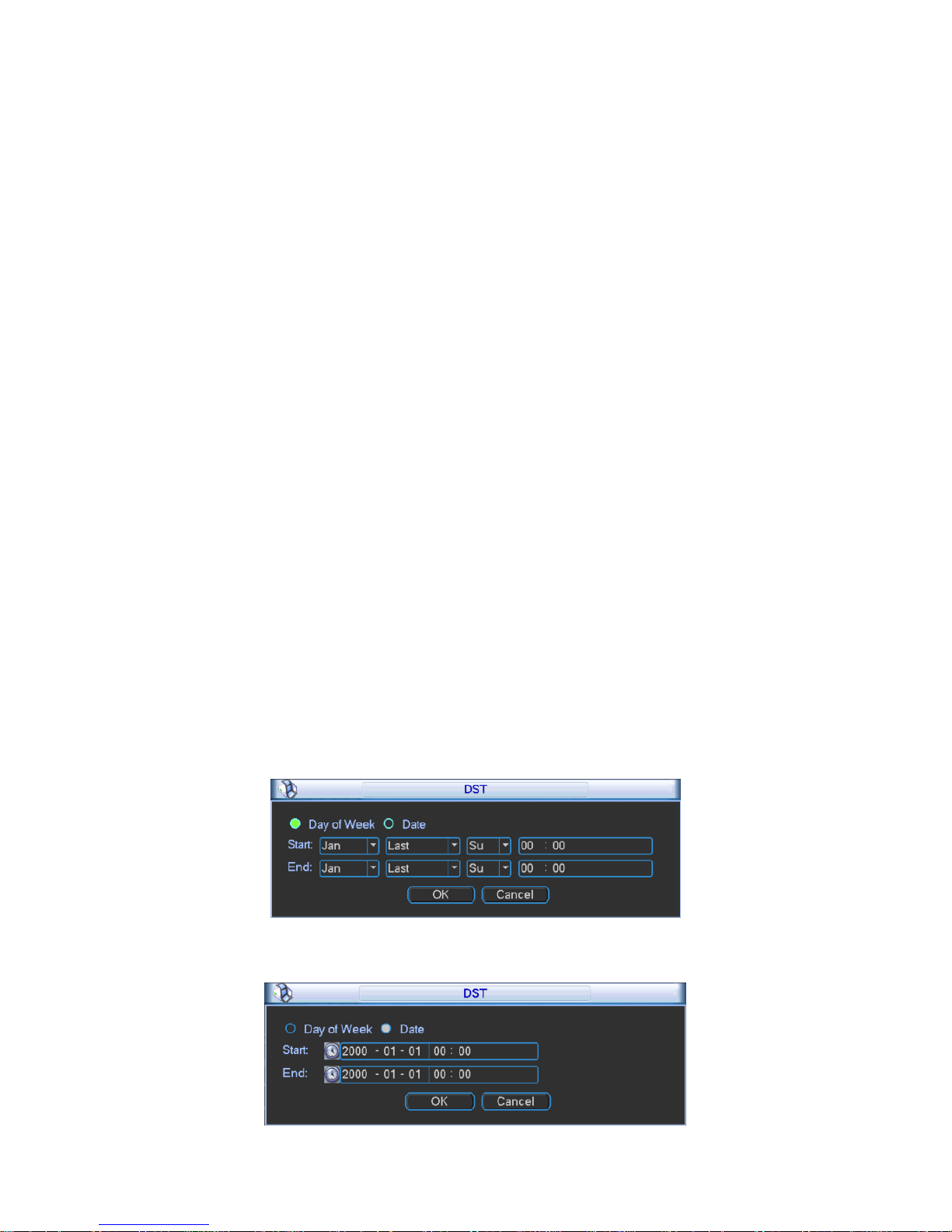
DST: Here you can set DST time and date. Please enable DST function and then click set
button. You can see an interface is shown as in Figure 3- 32. Here you can set start time
and end time by setting corresponding week setting. In Figure 3- 32, enable date button, you
can see an interface is shown as in Figure 3- 33. Here you can set start time and end time
by setting corresponding date setting.
Figure 3- 32
Page 49

44
Figure 3- 33
Note: Since system time is very important, do not modify time casually unless
there is a must!
Before your time modification, please stop record operation first!
3.2.4.2 Encode
Encode setting interface is shown as below. Please see Figure 3- 34.
Figure 3- 34
Slot: To select the slot you want.
Channel: To select the channel you want.
Signal type: Please select from the dropdown list.
Type: Select from regular, detect and alarm.
Compression: System supports H.264.
Profile: Main and Baseline.
Resolution: System supports various resolutions, you can select from the dropdown list. The
standard definition main stream supports D1/HD1/2CIF/CIF/QCIF and the high definition
main stream supports 1080P/720P/D1 and etc. Please note the option may vary due to
different series.
Frame rate: Pal standard: 1 frame/s – 25 frame/s. NTSC standard: 1 frame/s – 30 frame/s.
Bit rate type: System supports two types: CBR and VBR. You cannot set image quality
under CBR. In VBR mode, you can set video quality. There are six levels ranging from 1 to 6.
The sixth level has the highest image quality.
Bit rate: To set bit stream value to change image quality. The higher the rate, the better the
image quality. There is recommended bit stream value for you to refer.
Page 50

45
Video/audio: You can enable or disable the video/audio. Main bit stream video by default is
ON. For extra bit stream, you must select video prior to selecting audio.
Audio format: You can select audio format: G711a, G711u and PCM.
Note: In encode setup, you cannot set encode parameter for remote device.
3.2.4.2.1 Overlay
Click overlay button, you can see an interface shown in Figure 3- 35.
Figure 3- 35
Cover area (Privacy mask): Display as . To set cover area. You can drag you mouse to set
proper area size. In one channel video, system max supports 4 zones in one channel.
Preview: Preview means the cover area cannot be viewed by user when system is in
preview status.
Monitor: Monitor means the cover area cannot be view by the user when system is in
monitoring status.
Time display: You can select whether system displays time or not in decoding data for
playback. Please set button and then drag the title to the corresponding position in the
screen.
Channel display: You can select whether system displays channel number or not in
decoding data for playback. Please click set button and then drag the title to the
corresponding position in the screen.
Note: Titles cannot overlay each other.
3.2.4.3 Schedule
After system booted up, it is in default of not recording. You can set record type and time in
menu system settings schedule. Please see Figure 3- 36.
Page 51

46
Figure 3- 36
Analog channel: Please select the channel number first.
Slot: Please select the slotl number first. You can select “all” if you want to set for the whole
slots.
Video input: Please select the channel number first. You can select “all” if you want to set for
the whole channels.
Snapshot: Enable it by checking and then you may schedule snapshot. It snapshots 1/s
by default. You can modify it in encode setup.
Holidays: Enable it by checking . You may set vacation mode up to one month.
Period: You may set period for general recording as video recording is operating within this
time period. You may set by day of week while each day has setting in six periods. You can
select “all” if you want to set all days at once.
Pre-record: System can pre-record the video before the event occurs into the file. The value
ranges from 0 to 30 seconds depending on the bit stream.
Note: Pre-record time depends on its bit stream as pre-record time may not be
reached in case of large bit stream.
Record types: There are three types: regular, motion detect (MD) and alarm.
At the bottom of the menu, there are color bars for your reference. Green color stands for
regular recording; yellow color stands for motion detect.
Note: Settings in analog and digital channels are similar.
Page 52

47
Figure 3- 37
Device: Remote device IP address.
Channel: Remote device channel no.
Quick Setting
1) This function allows you to copy one channel setting to another. After setting in channel 1,
you can click copy button and turn to channel 3 and then click paste button or vice versa.
2) You can finish setting for one channel and then click save button or you can finish all setting
and then click save button to memorize all the settings.
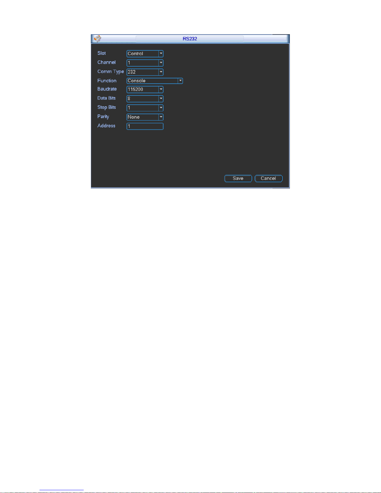
3.2.4.4 RS232
RS232 interface is shown below as in Figure 3- 38.
Page 53
48
Figure 3- 38
Function: There are various devices for you to select. Console is for you to use the COM or
mini-end software to upgrade or debug the program. The keyboard is for you to control the
device via the special keyboard. Adapter is to connect to the PC to transfer data directly.
Net keyboard is for you to use the special keyboard to control the device. MatrixCom is to
connect to the peripheral matrix control. PELCO is for you to control matrix via PELCO.
Baud rate: You can select proper baud rate.
Data bit: You can select proper data bit. The value ranges from 5 to 8.
Stop bit: There are two values: 1/2.
Parity: there are four choices: odd/even/space/mark.
System default setting is:
Function: Console
Baud rate:115200
Data bit:8
Stop bit:1
Parity: None.
Address: You can set address.
3.2.4.5 Network
Network interface is shown below as in Figure 3- 39.
Page 54

49
Figure 3- 39
Network Mode: It includes multi-addresses, fault tolerance, load balance, net bridge and
link aggregation.
Aggregation Set: Under net bridge mode under.
Net bridge Set: Under net bridge mode only. This setup can bind any two network cards
to one net bridge as one network card can only bind one net bridge. Bound net bridge
will be shown in Ethernet dropdown box. Bound network card as net bridge will be not
shown.
Ethernet Card Name: You can select from 1~~2.
Default Ethernet port: You can select from 1~~2. Under multiple addresses and bridge mode
only.
Aggregation strategy: Under aggregation link mode only. Strategies available are MAC-
address-based, IP-address-and-port-based, IP-address-and-MAC-address-based. IP-
address-and-port-based.
IP version: IPv4 and IPv6.
IP address: Here you can input IP address and then set corresponding subnet mask and default
gateway.
DHCP: It is to auto search IP. When enable DHCP function, you cannot modify IP/Subnet
mask /Gateway. These values are from DHCP function. If you have not enabled DHCP
function, IP/Subnet mask/Gateway display as zero. You need to disable DHCP function to
Page 55

50
view current IP information. You must set IP-related parameters again if you disabled
DHCP. Besides, when PPPoE is operating, you cannot modify IP/Subnet mask /Gateway.
TCP port: Default value is 37777. You may set this port.
UDP port: Default value is 37778. You may set this port.
HTTP port: Default value is 80.
Max connection: connections: 0-128. System supports maximal 128 users. 0 means there is
no connection allowed.
Preferred DNS server: Set DNS server IP address.
Alternate DNS server: Set DNS server alternate IP address.
Transfer mode: Here you can select the priority among fluency/video qualities/self-adaption.
LAN download: Under sufficient bandwidth, system can process the downloaded data first if
you enable this function. The download speed is 1.5X or 2.0X of the normal speed.
LAN service: Click to enter LAN service setting as shown in Figure 3- 40.
Figure 3- 40
3.2.4.5.1 IP Filter
Only IP listed on trusted sites can connect to this device. Trusted sites supports up to 64 IP
addresses.
If you disable trusted sites, then there will be no limit for IP address to visits this device. Please
see Figure 3- 41.
Page 56

51
Figure 3- 41
3.2.4.5.2 NTP Setting
Figure 3- 42
You need to install SNTP server (Such as Absolute Time Server) in your PC first. In Windows 7
OS, you can use command “net start w32time” to boot up NTP service.
NTP setting interface is shown as in Figure 3- 42.
Host IP: Input your PC address where SNTP server is installed.
Port: This SNTP supports TCP transmission only. Port default value is 123.
Time zone: select your corresponding time zone here.
Here is a sheet for your time zone setting.
City /Region Name
Time Zone
London
GMT+0
Berlin
GMT+1
Cairo
GMT+2
Moscow
GMT+3
Page 57

52
New Deli
GMT+5
Bangkok
GMT+7
Beijing (Hong Kong)
GMT+8
Tokyo
GMT+9
Sydney
GMT+10
Hawaii
GMT-10
Alaska
GMT-9
Pacific Time(P.T)
GMT-8
American Mountain Time(M.T)
GMT-7
American Central Time(C.T)
GMT-6
American Eastern Time(E.T)
GMT-5
Atlantic Time
GMT-4
Brazil
GMT-3
Middle Atlantic Time
GMT-2
Update interval: minimum value is 1. Max value is 65535. (Unit: minute)
3.2.4.5.3 Multicast
After multicast is enabled, it will automatically get multicast address and add ins group. Open
preview to monitor via multicast.
3.2.4.5.4 DDNS
DDNS setting interface is shown as in Figure 3- 43.
Figure 3- 43
You need a PC of fixed IP in the internet and there is the DDNS software running on this PC. In
other words, this PC is a DNS (domain name server).
In network DDNS, please select DDNS type (currently support CN99 DDNS,NO-IP DDNS,
Private DDNS and Dyndns DDNS which can coexist )and highlight enable item. In host IP, input
DDNS name allowing you to connect to WEB search page of the device.
Note: Private DDNS function shall work with special DDNS server and special
Professional Surveillance Software (PSS).
Page 58

53
3.2.4.5.5 UPNP
Figure 3- 44
The UPNP protocol is to establish a mapping relationship between the LAN and the WAN.
Please see Figure 3- 44.
UPNP on/off :Turn on or off the UPNP function of the device.
Status: Display UPNP function status, including success, fail and searching.
Router LAN IP: It is the router IP in the LAN.
WAN IP: It is the router IP in the WAN.
PAT table:Display info of added ports.
You may add new port and delete existing port.
Note: Double clicke item; you can change the corresponding mapping information.
Please see Figure 3- 45.
Figure 3- 45
3.2.4.5.6 Email
Page 59

54
Email setting interface is shown as in Figure 3- 46.
Figure 3- 46
SMTP server: Please input your email SMTP server IP here.
Port: Please input corresponding port value here.
User name: Please input the user name to login the sender email box.
Password: Please input the corresponding password here.
Sender: Please input sender email address here.
Title: Please input email subject here. System support English character and Arabic number.
Max 32-digit.
Interval: The send interval ranges from 0 to 3600 seconds. 0 means there is no interval.
Please note system will not send out the email immediately when the alarm occurs. When the
alarm, motion detect or the Abnormality event activates the email, system sends out the email
according to the interval you specified here. This function is very useful when there are too many
emails activated by the Abnormality events, which may result in heavy load for the email server.
Health email enable: Please check the box here to enable this function. This function allows
the system to send out the test email to check whether the connection is OK or not. Select
this function and then set interval for those test email. The send interval ranges from 30 to
1440 minutes.
Note: Click test button to test whether current EMAIL config is OK.
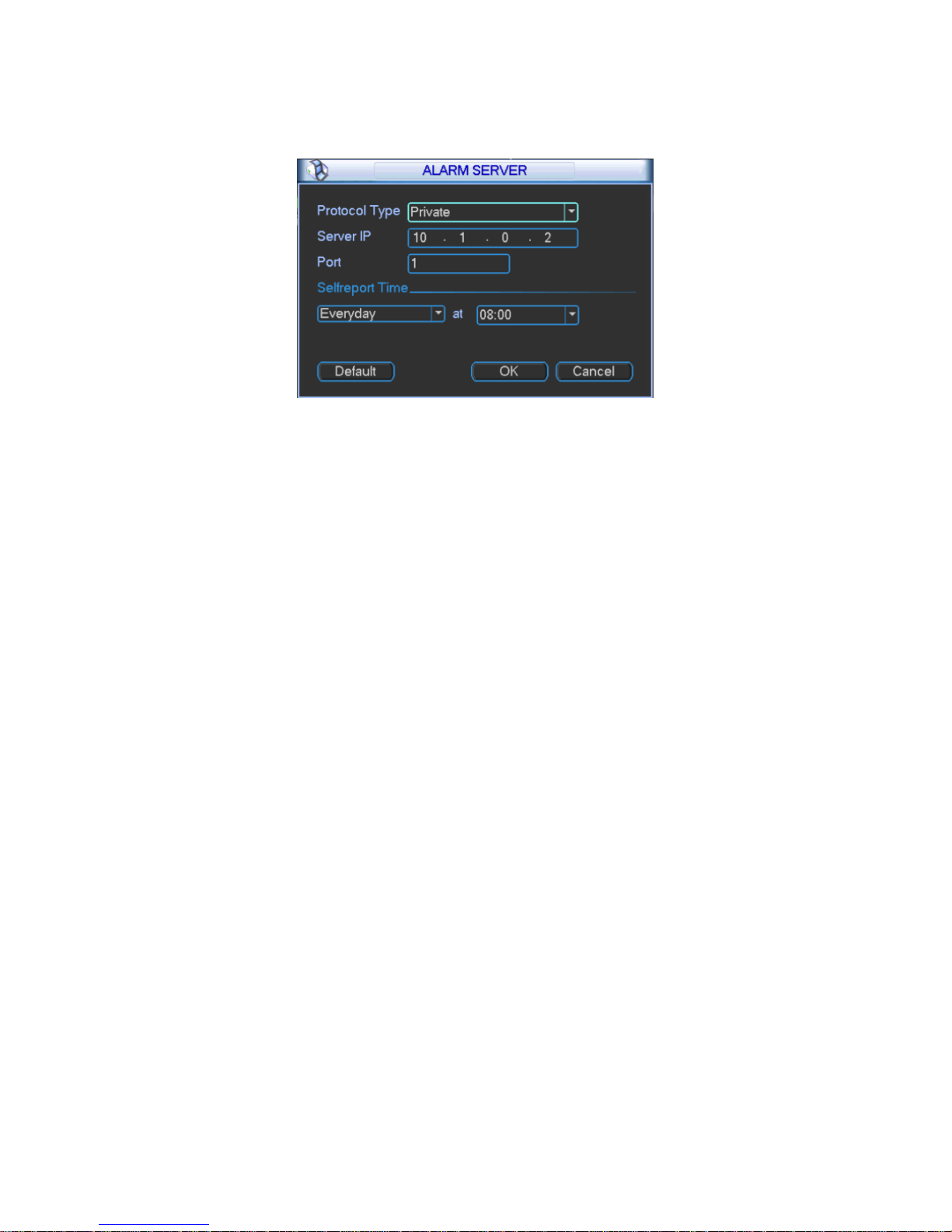
3.2.4.5.7 Alarm Center
This interface is reserved for you to develop. If alarm occurs locally, its alarm signal will be
uploaded to alarm center. For you to use alarm center, please set server IP and port first. When
Page 60
55
alarm occurs, the device will send data according to protocol format and client will receive
designated data. Please see Figure 3- 47.
Figure 3- 47
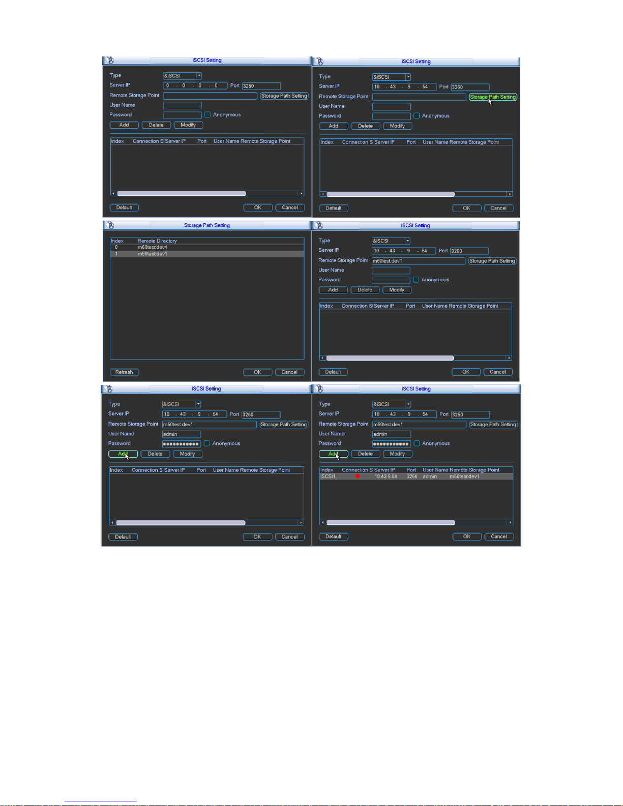
3.2.4.5.8 iSCSI
1) Click system setting network network service setting iSCSI setting. Set its
parameter, including host IP, port.
2) Click storage path setting.
3) Select corresponding remote directory and then click OK to enable.
4) Input correct username and password. Click Add.
5) Click OK.
Please see Figure 3- 48 as guide.
Page 61
56
Figure 3- 48
3.2.4.6 Video Detection
Introduction:
1) Please set in menu system settings detect.
2) There are no settings of detection area, sensitivity or anti-dither in video loss and camera
mask.
3) You can drag your mouse to set motion detect area. You may right click to save your
selection and exit setting. Please click save before you exit.
Page 62

57
3.2.4.6.1 Motion detect
When the system detects dynamic signal that reaches preset sensitivity via analyzing video
image, motion detect alarm will turn on. The interface is shown below as in Figure 3- 49.
Figure 3- 49
Note: Please make sure you have enabled motion detect function as the check box
filled by ■.
Event type: from the dropdown list you can select motion detect type.
Slot: select slot to set.
Enable: ■ means selected.
Channel: select the channel to activate motion detect or select all to include all channels
under selected slot.
Region: Move cursor to set, and click enter. The interface is shown as in Figure 3- 50. The
green zone is current cursor position. Grey zone is the motion detect zone. Black zone is the
disarmed zone. Do remember click save button to save current setting. If you click ESC
button to exit the region setting interface system will not save your zone setting.
Page 63

58
Figure 3- 50
Sensitivity: System supports 1-6 levels. The sixth level has the highest sensitivity.
Period: Click set button, you can see an interface is shown as in Figure 3- 50. You may set
period of motion detect and during other periods, motion detect will remain off.
Select designated days of week with six periods per day available for selection. You must
check the front box to activate corresponding period. Select all if you want set all periods at
once.
Besides the above method, you also may set period by week day and week end.
Week day and weekend setting:
1. From the dropdown list you can select week day or weekend and then click the set button
at the right. You will see setting for you to define your week day and weekend. For
example, you may set Monday to Friday as week days and Saturday and Sunday as
weekends. Please save your setting. Please see Figure 3- 52 and Figure 3- 53.
2. Set periods for your week days and weekends.
Figure 3- 51
Page 64

59
Figure 3- 52
Figure 3- 53
Anti-jitter: Here you can set anti-jitter time. If anti jitter is set to be 10s, then when motion
detect is triggered, this signal will lasts 10s. Currently this function is on motion detect only.
The value ranges from 5 to 600s.
Alarm output: Select alarm output channel (reselectable). When alarm occurs, system will
automatically enable this alarm channel.
Delay: When motion ends, alarm delays for a certain period before it stops. Unit is second
with range between 10 to 300.
Show message: System can pop up a message to alarm you in the local host screen if you
enabled this function.
Alarm upload: System can upload the alarm signal to the network (including alarm centre) if
you enabled this function.
Send email: System can send out email to alert you when alarm occurs.
Record channel: Select designated record channel (same channel can be selected more
than once). When alarm occurs, system will automatically record selected channel.
Delay: When motion detect stops, recording will continue for a set period of time which
ranges from 10s to 300s.
Snapshot: Enable snapshot by checking ■. Snapshot when motion detection starts. Click
select to set certain channels. See Figure 3- 54.
Page 65

60
Figure 3- 54
Buzzer: Buzzer rings when motion detection alarms.
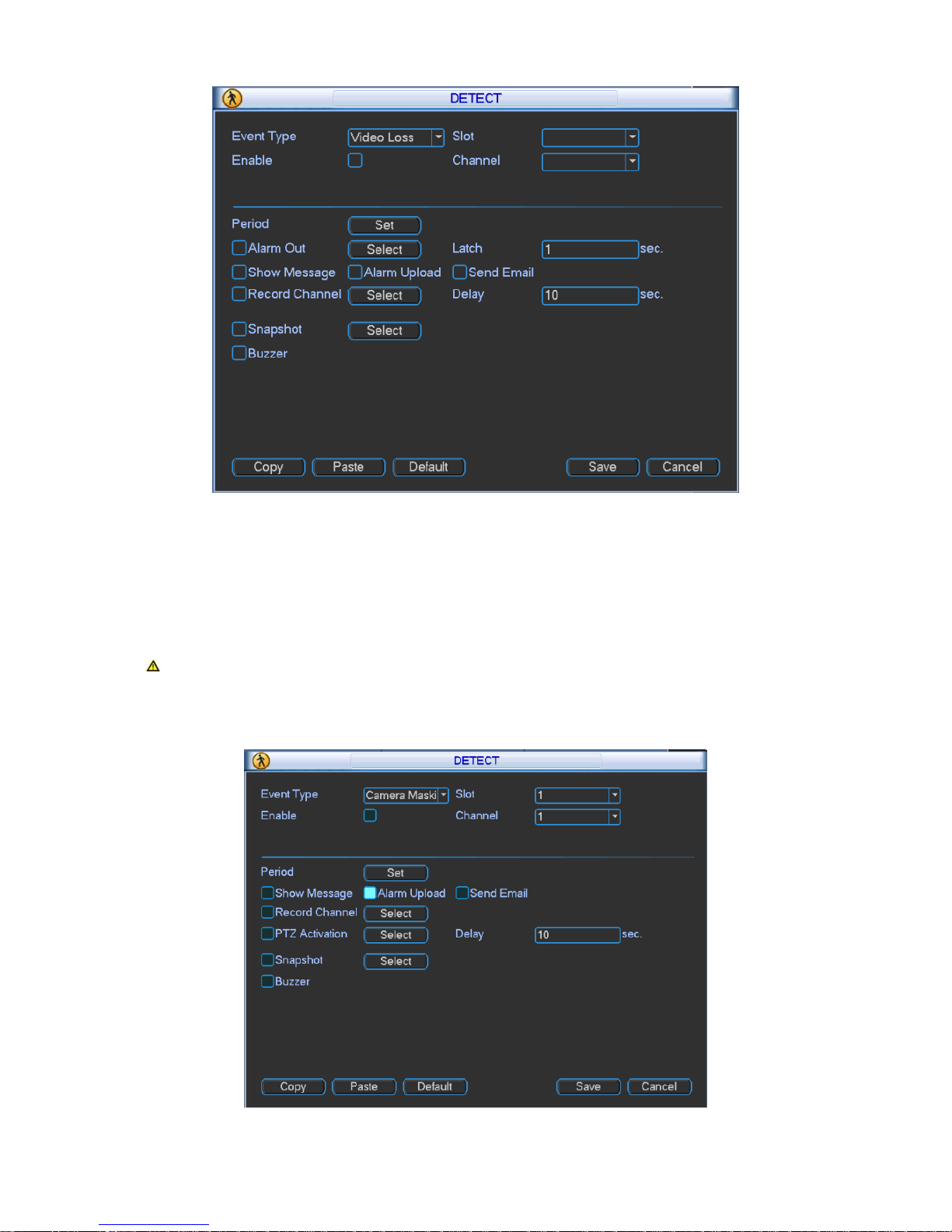
3.2.4.6.2 Video Loss
Page 66
61
Figure 3- 55
In Figure 3- 55, select video loss from the type list. This function allows you to be informed
when video loss occurred. You can enable alarm upload, send email and screen prompt
function.
Note: You can refer to setting in motion detect.
3.2.4.6.3 Camera Masking
Figure 3- 56
Page 67

62
Camera masking interface is shown as in Figure 3- 56.
When someone viciously masks the lens, or the output video is in one-color due to the
environments light change, the system can alert you to guarantee video continuity. You may
enable alarm upload, show message and send email function for alert.
Note: You can refer to setting in motion detect .
Explanation
1) In Detect interface, copy/paste function is only valid for the same type, which means you
cannot copy a channel setting in video loss mode to camera masking mode. (i.e. Camera
masking setting of channel 1 can be pasted to camera masking of other channels, but
cannot be pasted to other settings
2) You can only perform default operation for detection type in your current channel. (i.e.
When you operate in camera masking interface, your default operation will not affect
detection settings other than camera masking.)
Note: In motion detect settings, copy/paste function is not valid for area
parameters since video content in each channel are different.
3.2.4.7 PTZ
Step 1. PTZ and speed dome connection is right. Speed dome address setting is right.
Step 2. Speed dome A and B line connect properly with A and B line.
Step 3. In the main menu, click setting, and then click PTZ Control button. The interface
is shown as in Figure 3- 57. Here you can set the following items:
Slot: Select slot to connect.
PTZ Comm: Select local serial.
Protocol: select corresponding PTZ protocol(such as PELCOD)
Address: default address is 1. (This address must be identical with speed dome,
otherwise control over PTZ is invalid.)
Baud rate: select corresponding baud rate. Default value is 9600.
Data bits: select corresponding data bits. Default value is 8.
Stop bits: select corresponding stop bits. Default value is 1.
Parity: Default setting is none.
Page 68

63
Figure 3- 57
When card of corresponding slot is fiber encoding card and HDCVI encoding card, you can set
countercharge front-end function. See Figure 3- 58.
Figure 3- 58
After above setting is complete, as may countercharge front-end via video line, please refer to
RS 485 control.
3.2.4.8 Display
Page 69

64
Display is shown below as in Figure 3- 59, Figure 3- 60 and Figure 3- 61.
Figure 3- 59
Page 70

65
Figure 3- 60
Page 71

66
Figure 3- 61
Channel/output name: Click channel/output name to enter channel name interface where
you may edit channel name. (support maximal 20 characters, which may vary among
versions)
Page 72

67
Figure 3- 62
Color setting: Click to enter image color output setting. Please see Figure 3- 62.
Decoder screen setting: Click to enter setting of decoder screen. Please see Figure 3- 63.
Figure 3- 63
Page 73

68
3.2.4.9 Default
The default interface is shown in Figure 3- 64.
Figure 3- 64
Click default icon, system pops up a dialogue box. Please see Figure 3- 64.
Please highlight icon to select the corresponding function.
After all the settings please click save button, system goes back to the previous menu.
Note: System menu color, language, video standard, IP address, user account will not
maintain previous setting after default operation!
3.2.5 Advanced
Double click advanced icon in the main window, the interface is shown below as in Figure 3- 65.
There are total six function keys: HDD manage, abnormality, record, account, auto maintain,
cubeless video wall and Raid.
Page 74

69
Figure 3- 65
3.2.5.1 HDD Management
Here is for you to view and implement hard disk management. In menu, click advanced setting
and then click HDD manage. Please see Figure 3- 66.
You can see current HDD name, type, status, free capacity and total capacity. Operation include
modify HDD property, change to read-write disk, read only disk, and clear disk. You must save
your changes and reboot device before updated changes come effective. When HDD has error,
you may recover HDD.
Page 75

70
Figure 3- 66
Type: write-read disk and read-only disk.
HDD: Set current port input remote storage directory or external HDD no.
Channel
HDD channel: You can set HDD channel according to your actual condition. Slot sets local video
input. Digital channel sets remote video input.
Please see Figure 3- 67.
Figure 3- 67
Format: Format disk, clear data.
3.2.5.2 Abnormality
Page 76

71
Figure 3- 68
Abnormality interface is shown as in Figure 3- 68. In menu, click advanced setting and then
click Abnormality.
Event type: There are several options for you such as disk error, no disk, disconnection,
IP conflict, MAC conflict and etc. You can set one and more events.
Enable: ■ as selected.
Alarm Out: Select channel to alarm out. When alarm occurs, system automatically
enables the alarm channel(s).
Latch: Alarm latches one period and stops. Unit is second with range between 10 and
300.
Show message: system can pop up the message in the local screen to alert you when
alarm occurs.
Alarm upload: System can upload the alarm signal to the network (including alarm centre)
if you enabled current function.
Send email: System can send out email to alert you when alarm occurs.
Buzzer: ■ as selected. Highlight the icon to enable this function. The buzzer beeps when
alarm occurs.
3.2.5.3 Record
You may manually control records from each slot, each channel and network devices. Please
see Figure 3- 69.
Page 77

72
Figure 3- 69
3.2.5.4 Account
Figure 3- 70
Here is for you to implement account management. Please see Figure 3- 70.
For account management please note:
For the user account name and the user group, the string max length is 6-byte. The
backspace in front of or at the back of the string is invalid. There can be backspace in the
Page 78

73
middle. The string includes the valid character, letter, number, underline, subtraction sign,
and dot.
System account adopts two-level management: group and user. No limit to group or user
amount. For group or user management, there are two levels: admin and user.
One user should belong to one group. User right cannot exceed group right.
Figure 3- 71
Password Change
Please select the account from the dropdown list, input the old password and then input the new
password twice. Click the Save button to confirm current modification. The password max length
is 6-byte and first byte cannot be empty. Please see Figure 3- 71.
For the users of user account right, it can modify password of other users.
Page 79

74
Figure 3- 72
Add Group
You can add group by inputting group name and then inputting some memo information if
necessary.
Enter add group interface and select rights over control panel, shut down, real-time monitor,
playback, record, record file backup, PTZ, user account, system information view, alarm
input/output setting, system setting, log view, clear log, upgrade system, control device and etc.
Please see Figure 3- 72.
Modify Group
The modify group interface is similar to Figure 3- 72.
Add User
Figure 3- 73
Add user interface is shown above as in Figure 3- 73.
There are four default users: admin/888888/666666 and hidden user “default”. The first three
users have passwords same as the usernames, respectively. Except user 6666, other users
have administrator right. Hidden user “default” is for system interior use only and cannot be
deleted. When there is no login user, hidden user “default” automatically login. You can set some
rights such as monitor for this user so that you can view some channel view without login.
After you enter add user interface, please input the user name, password, and select the group it
belongs to from the dropdown list. You may select same user more than once. You are able to
use this selected user on different clients at the same time. Then you can check the
corresponding rights for current user. User right cannot exceed group right.
For convenient user management, usually we recommend the general user right is lower than
the admin account.
Page 80

75
3.2.5.5 Auto Maintain
Figure 3- 74
Here you can set auto-reboot time and auto-delete old files setting. You can set to reboot device
by specified time. You can set to delete files or expired files for the specified days.
You can select proper setting from dropdown list. Please see Figure 3- 74.
After all the settings please click save button, system goes back to the previous menu.
3.2.5.6 Cubeless Video Wall
Here you can set cubeless video wall function. Please see Figure 3- 75.
Figure 3- 75
Page 81

76
Select config and click delete to delete config. Click add to add config of cubeless video wall.
Please see Figure 3- 76.
Figure 3- 76
Name: Name of the cubeless video wall.
Row: Set number of rows of the cubeless video wall.
Column: Set number of columns of the cubeless video wall.
Windows: Rank all splicing units.
Output screen: Output channel of each splicing unit.
For example, the cubeless video wall is 2*2 as in Figure 3- 77.
Figure 3- 77
Step 1. Set name, row and column of the cubeless video wall. Select output screen and click
apply. (You must click apply every time you select output screen). Click OK. You will see
Figure 3- 78.
Page 82

77
Figure 3- 78
Step 2. You can continue to add cubeless video wall or edit or delete added ones. Select
cubeless video wall and click remove to delete it.
Step 3. You can edit name of cubeless video wall as in Figure 3- 79.
Figure 3- 79
Step 4. Click OK.
Step 5. Click OK to see the configured cubeless video wall. You can find it in output list.
3.2.5.7 Raid
Config Raid for record storage.
Page 83

78
Figure 3- 80
Click Add to add new Raid. Select corresponding level.
Figure 3- 81
Page 84

79
Click hot spare manager to set Raid hot spare disk which improves security.
Figure 3- 82
3.2.6 Remote Device
Note: This function must work with DVR or IPC.
3.2.6.1 IP Search
1) In remote device interface, click IP search. You may search all remote devices in network.
The display includes IP address, port, manufacturer protocol and type, please see Figure 3-
83.
2) Check box in front of remote device you want to add. Multiple selections is allowed.
3) Click add to add device.
4) Click OK to complete operation.
Page 85

80
Figure 3- 83
3.2.6.2 Manually Add
1) In remote device, click manually add. A prompt pops up and you need to input device name,
manufacturer, IP address, TCP port, username, password and channel number. Please see
Figure 3- 84.
2) Make sure you save changes.
3) Add device into added device.
4) Click OKto complete operation.
Page 86

81
Figure 3- 84
3.2.7 Shutdown
Figure 3- 85
Double click shutdown button, system pops up a dialogue box for you to select. Please see
Figure 3- 85.
Logout menu user: log out menu. You need to input password when you login the next time.
Restart application: reboot .
Shutdown: system shuts down and turns off power.
Switch user: you can use another account to log in.
Shutdown menu includes the above four functions.
Page 87

82
4 Web Operation
4.1 Network Connection
Before web client operation, please check the following items:
Network connection is right for the device and PC.
PC network setting is right, including IP address, subnet mask and gateway. (If there is no
router in network, then allocate IP address in same net section. Otherwise, set gateway and
subnet mask.)Please refer to Chapter 3: main menusettingnetwork.
Use order ping ***.***.***.***( IP address) to check connection is OK or not. Usually the
return TTL value equal to 64.
Set Internet Explorer: Tools-Internet Option-Security-Custom Level. Enable or prompt
ActiveX and plug-in. IE7 and IE8 are preferred.
Open the IE and then input IP address.
System can automatically download latest web control and the new version can overwrite
the previous one.
If you want to un-install the web control, please run uninstall webrec2.0.bat. Or you can go to
C:\Program Files\webrec to remove single folder. Please note, before you un-install, please
close all web pages, otherwise the un-installation might result in error.
4.2 Login and Logoff
Figure 4- 1
Open IE and input address in the address field. For example, if your IP is 10.43.200.141, then
please input http:// 10.43.200.141 in IE address field and press enter. Please see Figure 4- 1.
Please input your user name and password. Default factory name is admin and password is
admin.
Note: For security reasons, please modify your password after you first login.
Then you can select the login mode: LAN and WAN.
Page 88
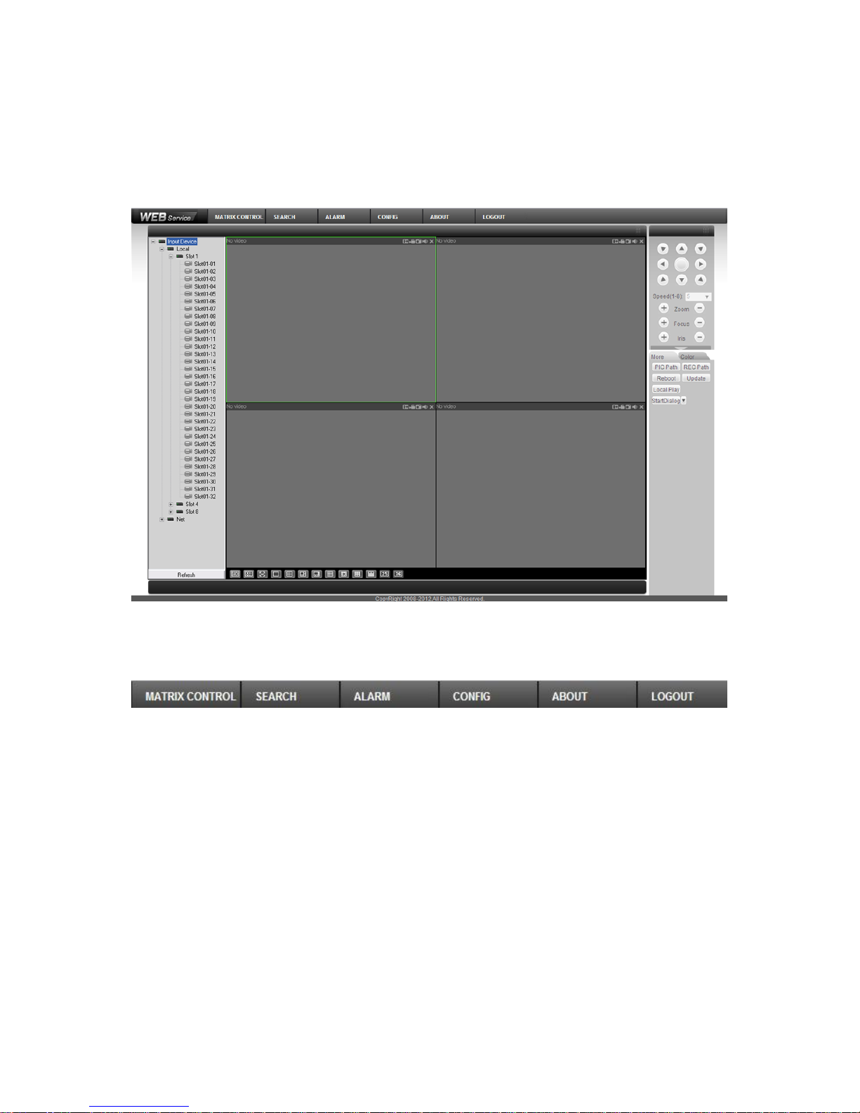
83
At login, system pops up warning information to ask you whether install webrec.cab control or not.
Please click yes button.
If you can’t download the ActiveX file, please make sure there is no plug-ins prohibiting this
ActiveX file and meanwhile lower your IE security level.
You will see the following interface after successful login in Figure 4- 2.
Figure 4- 2
1 System Menu
Figure 4- 3
The above Figure 4- 3 is system menu buttons.
2 Real-Time Monitoring
Click any channel to real-time monitor the channel. Monitoring window functions are summarized:
Display device info: Device IP, channel NO. and network monitor bit stream are displayed in
playing video. Otherwise no video displays.
Zoom in: Click this button and drag mouse to select any part in window. The selected part
will be zoomed in, and will return to original size with a right click.
Local record: Click this button to start recording. Records are saved in Record Download file
in system disk as default.
Snapshot: Click this button to snapshot video. Snapshots are saved in Picture Download file
in system disk as default.
Page 89

84
Audio: Whether turn on audio or not. (Note: Audio here is not related to audio in system
setting.)
Figure 4- 4
Close video: Close video window.
Switch between main/extra bit stream: Real time monitor the switch between main and extra
bit stream. Please see Figure 4- 5.
Figure 4- 5
Refresh: Refresh channel name list displayed on the left.
3 Input List
Local: Local input channel.
Network: Via network add to input channel into the device.
4 Refresh
Click refresh button to refresh local and network input list of adding device.
5 Monitoring Window Switch
Figure 4- 6
Device IP, monitor
channel No. and
network monitor
bit stream
From left to
right: zoom in, local
record, snapshot,
audio on, and
close video.
Page 90

85
Please see Figure 4- 6. From left to right are:
image quality
fluency
full screen
single window
four windows
six windows
eight windows
nine windows
thirteen windows
sixteen windows
twenty windows
twenty-five windows
thirty-six windows
You may flexibly adjust image fluency and real time performance.
6 PTZ Console
Before using PTZ Console, you must set PTZ protocol (please see PTZ setting in system
settings), otherwise you cannot access PTZ control operation.
You may control the direction, step length, zoom, focusing, iris, preset, point-to-point tour, pattern,
auto scan, lighting, wiper, horizontal rotation and other controls.
Step length: It is mainly used to control directions, for example rotation speed of step length 8 is
much faster than of step length 1.
PTZ rotation: It supports 8 directions: up, down, left, right, upper left, upper right, lower left and
lower right.
Page 91

86
Figure 4- 7
Hide PTZ
Console
Page 92

87
Figure 4- 8
Please see Figure 4- 7 and Figure 4- 8.
Auto scan: Select left border of camera auto scan via direction buttons, and click left border
button to confirm. It is same for right border.
Preset: Rotate the camera to designated position via direction buttons. Input preset value in
corresponding box, and click add button to save.
Auto tour: Input auto tour path value in point-to-point auto tour box. Input preset value in
correspond box and then click add button. You may repeat this process to add multiple presets.
You may delete preset by clicking on delete button.
Pattern: You may record down the above operations as Pattern X by click start to record button.
Then you should refer to Figure 4- 7 to perform zooming, focusing, iris, direction and etc. You
can stop recording by pressing stop button.
Assistant: select one item on assistant list and then click start or stop button. Please see Figure
4- 9.
Figure 4- 9
Matrix: It includes monitor output, video input, matrix ID and video switch.
Page 93

88
Light Wiper: Remote control over light and wiper.
On: Select speed dome image, click ON to overlay.
Off: Turn off overlay.
Up/down/left/right: Select menu item.
7 Image/Other Settings
Image setting: select one channel with green box and you may set the brightness, contrastness,
hue, and saturation. Please see Figure 4- 10.
Figure 4- 10
Other settings:
1) Click snapshot path or record path button to modify storage path. Please see Figure 4- 11.
Figure 4- 11
2)Click reboot device. You will see a pop-up box as in the left picture in Figure 4- 12 and click OK
to reboot.
Note: Before you reboot please be notified: 1. You must have authority to reboot
device; 2. There is no other users logging in system menu locally.
If someone is logging in system menu or you do not have the authority, you will see
the following box as in the right picture in Figure 4- 12.
Figure 4- 12
Page 94

89
1) Update
Click update button, and select updating file. Please see Figure 4- 13, Figure 4- 14 and Figure 4-
15.
Figure 4- 13
Figure 4- 14
Figure 4- 15
Click BIOS to start updating.
Page 95

90
2) Local Playback
Web support playback of record file saved on PC. Click local playback, you will see a prompt box
as in Figure 4-16. You need to select file to playback.
Figure 4- 16
4.2.1 Matrix Control
Via matrix, you can slit TV wall, and complete output and input config.
Step 1. Click matrix control to enter interface in Figure 4- 17.
Figure 4- 17
Please see Figure 4- 17 and Figure 4- 18.If system has just upgraded, then click Save to see the
following.
Page 96

91
Figure 4- 18
Step 2. If you want to add new card or delete output screen and add again, please select
to add and click Save.
Step 3. Select slot to config. See Figure 4-19.
Page 97

92
Figure 4- 19
The red area can be dragged to move.
Step 4. Click Splice, and select area to splice, click OK.
Step 5. Click Scheme.
Step 6. Right click scheme to add. Later, you can right click a certain scheme to rename and
delete, or double click scheme to operate. This step may also be performed after all
operations are complete. Output screen and input device config will not be lost.
Step 7. If you have uploaded background and would use this function, check background, and
select picture to upload. All output screen without input device will show this background.
Step 8. Select screen or output screen on the left and then select split mode and group no.
Cubeless video wall can split into 1, 4, 8, 9, 16 and free split (free split is for tour and can
use auto alignment).
Step 9. You can modify decode strategy, and you may drag according to live to fluent.
Step 10. Input device list, including local, net, input group and favorites. Select input device and
drag to window to decode. If input device supports e-zoom function, then click e-zoom.
Page 98

93
Step 11. You can refresh, add to favorites, sort favorites and add input group. Click add to
favorites and sort favorites.
Step 12. Enable tour. You can set tour interval time with 10-120s.
4.2.2 System Info
4.2.2.1 Version Info
Here you can view hardware features, software version and its release date. Please see Figure
4- 20.
Figure 4- 20
4.2.2.2 HDD Info
Here you can view HDD status, free space and total space.
Page 99

94
Figure 4- 21
4.2.2.3 Log
Here you can view system log.
System logs are classified into: system operation, config, data management, alarm event, record,
user, and deleted log. You can select classification to search by directly clicking on search button.
The system will display logs in list format. You may click backup button to record log on PC. If
you click delete button, the system will clear all log files.
Page 100

95
Figure 4- 22
4.2.2.4 System Status
Here you can view status of system CPU, memory, temperature, fan and power. Please see
Figure 4- 23.
 Loading...