

Page 1

Dahua Vandal Proof Wi-Fi Dome Camera Quick Start Guide
V 1.0.1
Zhejiang Dahua Vision Technology CO., LTD
Page 2
1
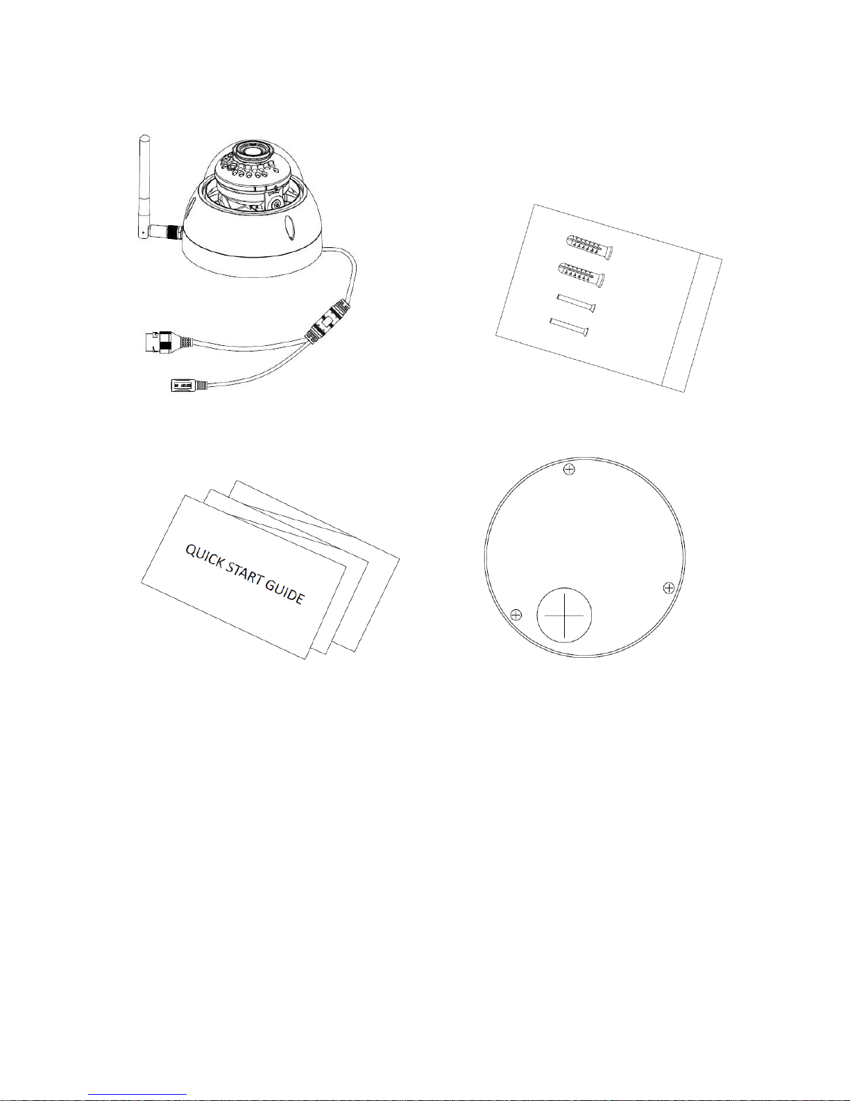
1 Packing List
Device × 1 Screw Package ×1
QSG ×1 Installation Position Map×1
Page 3

2
2 Product Appearance
Figure 2-1
Please refer to the following sheet for more details about the device.
SN
Name
①
Dome cover
②
Dome enclosure
③
Network Port
④
Power Port
Sheet 2-1
Page 4

3
Figure 2-1
Please refer to the following sheet for more details about each component.
Sheet 2-2
Note:
For reset, long press for 8 seconds and then the light off; For WPS (Wi-Fi Protected Setup), one quick
press.
Please refer to the following sheet for more details about status of indicator light.
Indicator light status
Device status
Red light normally on
Booting
Green light slow flashing
Booting completed, await wifi config,
enter smart config status;
Green light quick flashing
Wifi smart config in progress, including
WPS (Wi-Fi Protected Setup),
management frame and etc.
Green light normally on
Wifi connection succeeded, operate
normally.
Red and green lights flash alternately
Device upgrade
Red light slow flashing
Network connection failure or
disconnection after network connection
success.
Red light quick flashing
Device malfunction, fail to boot up; alarm
or SD card malfunction
Sheet 2-3
SN
Name
①
Wireless antenna
②
Waterproof ring
③
Reset/ WPS (Wi-Fi Protected Setup) button
④
Micro SD card slot
⑤
Indicator light 1
⑥
Indicator light 2
Page 5

8
4 Device Installation
Important
Before the installation, please make sure the installation environment can at least support 3x weight of
the camera.
Figure 4-1
Step 1
Use inner hex wrench in the accessories bag to open dome enclosure by unfastening three inner hex
screws on enclosure.
Step 2
Please take out the installation position map in the accessories bag, and then paste it on the ceiling or
the wall according to your monitor area requirements.
Step 3
Find cross signs on the map, and dig three plastic expansion bolts holes on the installation surface
and then insert three expansion bolts in the holes. Secure these three bolts firmly.
Note:
If user pulls out cable from top of installation surface, you must dig an exit hole on installation
surface according to the installation position map.
If user pulls out cable from side of cable channel, it must go through the U-shape channel on
dome pedestal, and take out cable from the side exit hole on pedestal.
Step 4
Adjust the device installation pedestal to the proper position and then pull cable through the exit hole
on Installation surface. Make direction of TOP sign same as it on installation position map. Line up the
three screw holes in the device pedestal to the three plastic expansion bolt holes in the installation
Page 6

9
position. Put the three self-tapping screws in the three plastic expansion bolts firmly. Fix dome body on
installation surface.
Step 5
Hold both sides of the rotation bracket bottom with hands, rotate horizontally along the axis, and adjust
lens horizontal direction to designated position. Hold the LED decoration cover with hand, rotate along
the vertical direction, adjust the lens vertical direction to designated position; it is okay to loosen the fix
screws on both sides of the bracket first if it is too tight to adjust (just make it loose, do not take it
down), then adjust the lens, tighten the fix screws after adjustment. Hold the LED decoration cover
with hands, rotate horizontally along the axis, and adjust the lens image to designated position. Range
of lens: vertical (0°~+64°), horizontal (0°~+355°), image rotation direction (0°~+355°).
Note:
When it rotates to 64° vertically, please pay attention to the image rotation direction in order to avoid
the outer cover blocking IR light and influencing IR effect.
Note:
This quick start guide is for reference only. Slight difference may be found in user interface.
All the designs and software here are subject to change without prior written notice.
All trademarks and registered trademarks mentioned are the properties of their respective
owners.
If there is any uncertainty or controversy, please refer to the final explanation of us.
Please visit our website or contact your local service engineer for more information.
Zhejiang Dahua Vision Technology Co., Ltd
Address:No.1199 Bin’an Road, Binjiang District, Hangzhou, PRC.
Postcode: 310053
Tel: +86-571-87688883
Fax: +86-571-87688815
Email:overseas@dahuatech.com
Website: www.dahuasecurity.com
 Loading...