

Page 1

Smart Professional Surveillance System User’s Manual
Version 1.11.0
Page 2

i
Table of Contents
1 OVERVIEW AND ENVIRONMENT ..................................................................... 1
1.1 Overview .............................................................................................................................. 1
1.2 Performance ........................................................................................................................ 1
1.3 Environments ...................................................................................................................... 1
2 INSTALLATION AND UPGRADE ...................................................................... 2
2.1 Installation ........................................................................................................................... 2
2.2 Un-installation ..................................................................................................................... 5
3 SETTING ............................................................................................................ 7
3.1 Login Interface .................................................................................................................... 7
3.2 Main Interface ...................................................................................................................... 7
3.3 General ................................................................................................................................ 8
3.3.1 Basic ................................................................................................................................ 9
3.3.2 File Path ......................................................................................................................... 10
3.3.3 Alarm Prompt .................................................................................................................. 10
3.3.4 Version ........................................................................................................................... 11
3.4 Account ............................................................................................................................. 12
3.4.1 Add role .......................................................................................................................... 12
3.4.2 Add user ......................................................................................................................... 14
3.5 Device Manager ................................................................................................................. 15
3.6 Signals Manager ............................................................................................................... 20
3.6.1 General........................................................................................................................... 20
3.6.1.1 Network .................................................................................................................. 20
3.6.1.2 Remote .................................................................................................................. 27
3.6.1.3 Encode ................................................................................................................... 28
3.6.1.4 Image ..................................................................................................................... 32
3.6.1.5 PTZ Control ............................................................................................................ 32
3.6.2 Event ................................................................................................ .............................. 33
3.6.2.1 Video Detect ........................................................................................................... 33
3.6.2.2 Alarm ..................................................................................................................... 38
3.6.2.3 Abnormality ............................................................................................................ 41
3.6.2.4 Smart Config .......................................................................................................... 44
3.6.3 Record/Storage............................................................................................................... 48
Page 3

ii
3.6.3.1 Schedule ................................................................................................................ 48
3.6.3.2 Disk ................................................................ ........................................................ 52
3.6.4 Maintenance ................................................................................................................... 53
3.6.4.1 Account .................................................................................................................. 54
3.6.4.2 Maintenance ........................................................................................................... 56
3.6.4.3 WEB ....................................................................................................................... 61
3.7 Alarm Setup ....................................................................................................................... 61
3.7.1 Set Alarm Scheme .......................................................................................................... 61
3.7.2 Enable/Disable/Export Scheme ....................................................................................... 66
3.8 Video Wall Configuration .................................................................................................. 66
3.9 Tour &Task ........................................................................................................................ 70
3.10 PC-NVR .............................................................................................................................. 73
4 BASIC OPERATION ......................................................................................... 79
4.1 Liveview............................................................................................................................. 79
4.1.1 Real-time Liveview .......................................................................................................... 79
4.1.2 Record ............................................................................................................................ 82
4.1.3 Snapshot ........................................................................................................................ 82
4.1.4 PTZ ................................................................................................................................ 83
4.1.4.1 Preset..................................................................................................................... 84
4.1.4.2 Tour ....................................................................................................................... 84
4.2 Playback ............................................................................................................................ 85
4.2.1 Playback Device Record ................................................................................................. 87
4.2.2 Playback Local Record ................................................................................................... 89
4.2.3 Export ............................................................................................................................. 89
4.3 Alarm Manager .................................................................................................................. 89
4.4 Log ..................................................................................................................................... 90
5 EXTENSION ..................................................................................................... 92
5.1 Video Wall ......................................................................................................................... 92
5.2 E-map ................................................................................................................................ 94
5.2.1 Add E-map...................................................................................................................... 94
5.2.2 Edit E-map ...................................................................................................................... 95
5.2.3 Liveview E-map ................................................................ .............................................. 97
5.3 Device Display&Control .................................................................................................... 97
Page 4

iii
Welcome
Thank you for using our Smart Professional Surveillance System (SmartPSS)!
This user’s manual is designed to be a reference tool for operation of your system.
Here you can find detailed operation information about SmartPSS.
Page 5

1
1 Overview and Environment
1.1 Overview
SmartPSS is an abbreviation for Smart Professional Surveillance System.
The software is to manage small quantity security surveillance devices. It releases with the
device and does not support the products from other manufacturers. It has the following features:
View real-time video of several camera channels.
View the playback video files from various cameras.
Support multiple scheduled arms to realize auto PC guard.
Support e-map; you can clearly view and manage all device locations.
Video wall plan setup and can output video wall video at the same time.
Support extension applications, can send out alarm information to external programs.
1.2 Performance
System max supports 36-channel at CIF resolution.
Each stream media server max receives 16-channel video and transfers 128-chanel video.
Each storage server max supports to save 16-channel video (no bit stream limit).
1.3 Environments
Item
Requirements
OS
Windows 7/ Windows 8/ Mac (SmartPSS Mac version).
CPU
2.4GHz or higher.
Display card
Independent car and support directX 8.0c or higher.
Memory
1GB or higher.
Displayer
Resolution
1024×768 or higher.
Page 6
2
2 Installation and Upgrade
2.1 Installation
Double click “General_Smart-PSS_Eng_IS_VX.XX.X.exe” to begin installation. See Figure
2-1.
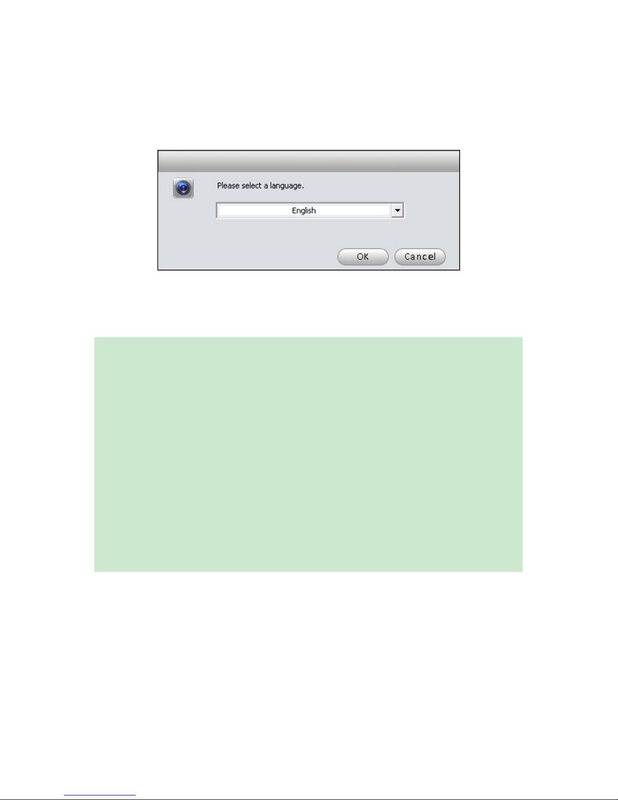
Figure 2-1
Select installation language from the dropdown list and then click OK button to go to
Welcome interface. See Figure 2-2.
Figure 2-2
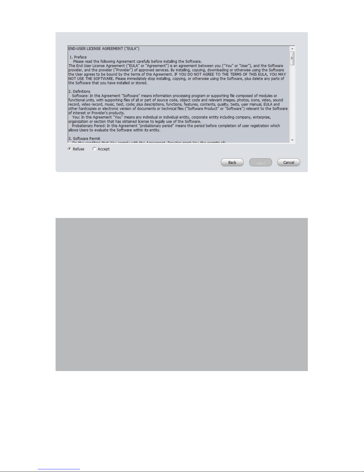
Click next button, you can see an interface is shown as in Figure 2-3. Here you can view
End User License Agreement.
Page 7
3
Figure 2-3
Please check the Accept item and then click Next button to continue. System pops up
module installation dialogue box. See Figure 2-4.
Figure 2-4
Check SmartPSS item and then click Next button, you can see there is an interface asking
you to specify installation path. See Figure 2-5.
Page 8
4
Figure 2-5
After you select installation path click Next button, system begins installation. The interface
is shown as in Figure 2-6.
Figure 2-6
During the installation process, you can click Cancel button to exit. After installation, you can
see an interface is shown as below. See Figure 2-7.
Page 9

5
Figure 2-7
Click Finish button, you can complete the installation.
2.2 Un-installation
1) From Start -> All programs->SmartPSS, select Uninstall SmartPSS item. System pops up
the following dialogue box. See Figure 2-8.
Figure 2-8
2) Click Next button, you can see an interface shown as in Figure 2-9.
Page 10

6
3) Check the box here to remove SmartPSS. You can check the box to remove PC-NVR too.
Click Uninstall button to remove.
Figure 2-9
Page 11

7
3 Setting
Double click SmartPSS icon , you can go to the login interface.
3.1 Login Interface
Login interface is shown as in Figure 3-1.
User name: Input the user account
Password: Please input corresponding password to log in.
OK: Click this button, system can verify the account and then enter the software main
interface.
Cancel: Click this button to exit login interface.
Note:
If it is your first time to run the SmartPSS program, default user name is admin and its
password is admin too. Admin is a super administrator and can not be removed. It can add,
modify or delete other user.
For security reason, please modify your password after first log in.
You can memory your password, so that when you can log in the next time, you do not need
to input user name and password. Please note this function is for your convenient only. Do
not enable this function in public PC.
Figure 3-1
3.2 Main Interface
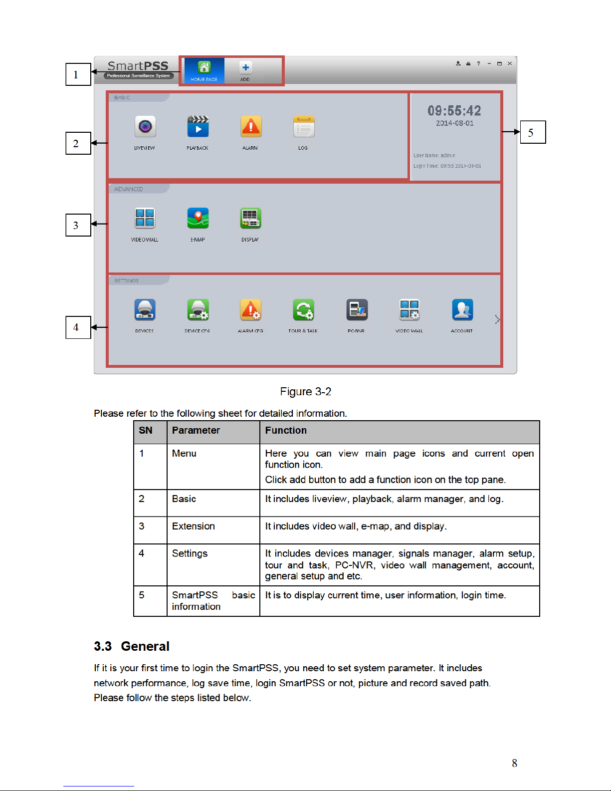
Click Login button, system begins verifying user name and password and then go to the main
interface. See Figure 3-2.
Page 12
Page 13
9
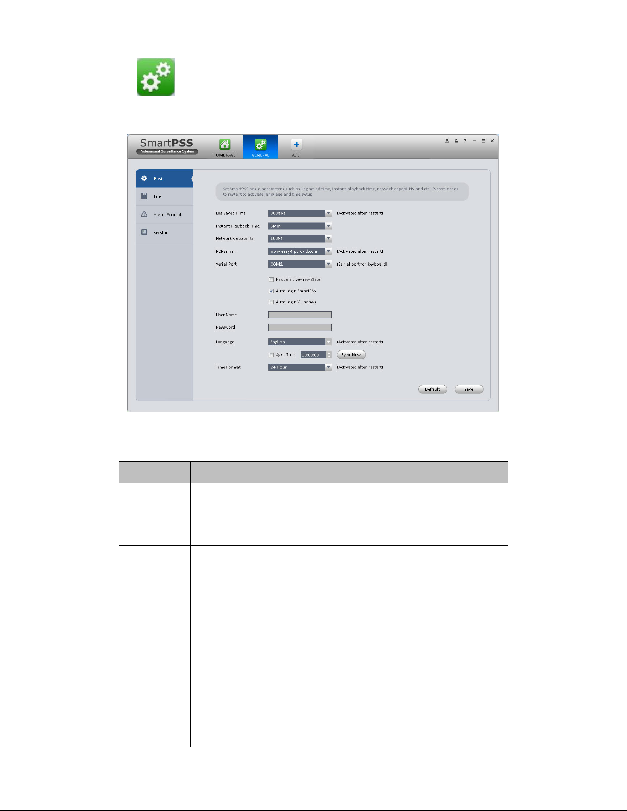
Click the button; you can go to the general interface. See Figure 3-3.
3.3.1 Basic
It is to set capability, language, time and etc.
Figure 3-3
Please refer to the following sheet for detailed information.
Item
Function
Log Saved
Time
Here you can set log save time. System automatically overwrites old
files once it reaches the period you set here.
Instant Play
Time
It is to set instant playback time.
Network
capability
It is for you to set network function. It includes: “Low”,
“10M”, ”100M”, ”1000M”.
Serial Port
Keyboard can select corresponding serial port to operate,
COM1~COM10 are available.
P2P Server
Select P2P server.
Resume
Previous
State
System restores previous liveview status after it restarts.
Auto Login
SmartPSS
Check the box here, you can login SmartPSS directly without
inputting user name and password.
Page 14
10
Item
Function
Auto Login
Windows
Check the box here and then input user name and password, you
can go to the Windows OS after the computer restarts.
Language
Software language.
Sync time
Check the box here to enable time synchronization function and
then input synchronization time. SmartPSS can auto synchronize
time with the PC at the time you specified.
Click Sync now button to begin synchronization now.
Time format
System time format. It includes 12H/24H.
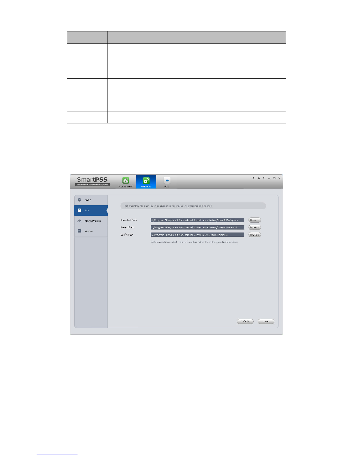
3.3.2 File Path
File configuration interface is shown as below. See Figure 3-4.
Here you can set snapshot picture and record file default save path.
Configuration file path: It is to import or export configuration file. If you change path to D disk, you
can export current software user information to D disk. If current software has installed at the D
disk, you can import user information to current software.
Figure 3-4
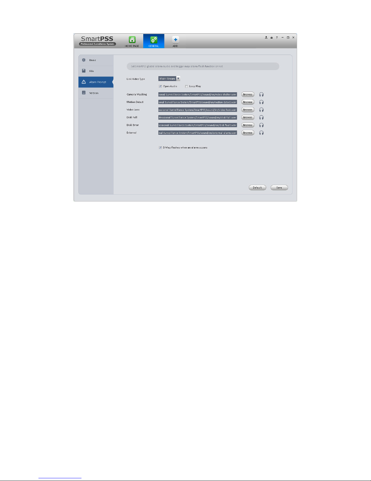
3.3.3 Alarm Prompt
It is to set alarm prompt audio. The interface is shown as below. See Figure 3-5.
Please select corresponding prompt audio for the specified alarm type.
Check the box at the bottom of the interface to enable e-map function. The e-map can flash
when the corresponding alarm occurs.
Page 15
11
Figure 3-5
Tips
You can click Default button to restore factory default setup.
User config file storage path is used to import and export user config file. If current user config
file storage path is modified to other path, then it means all users’ config info are exported. If user
re-install, he can export previous all user’s config info to current client.
If he re-install the software and import previously exported user config info, after being saved,
original user config info will be successfully imported into current client.
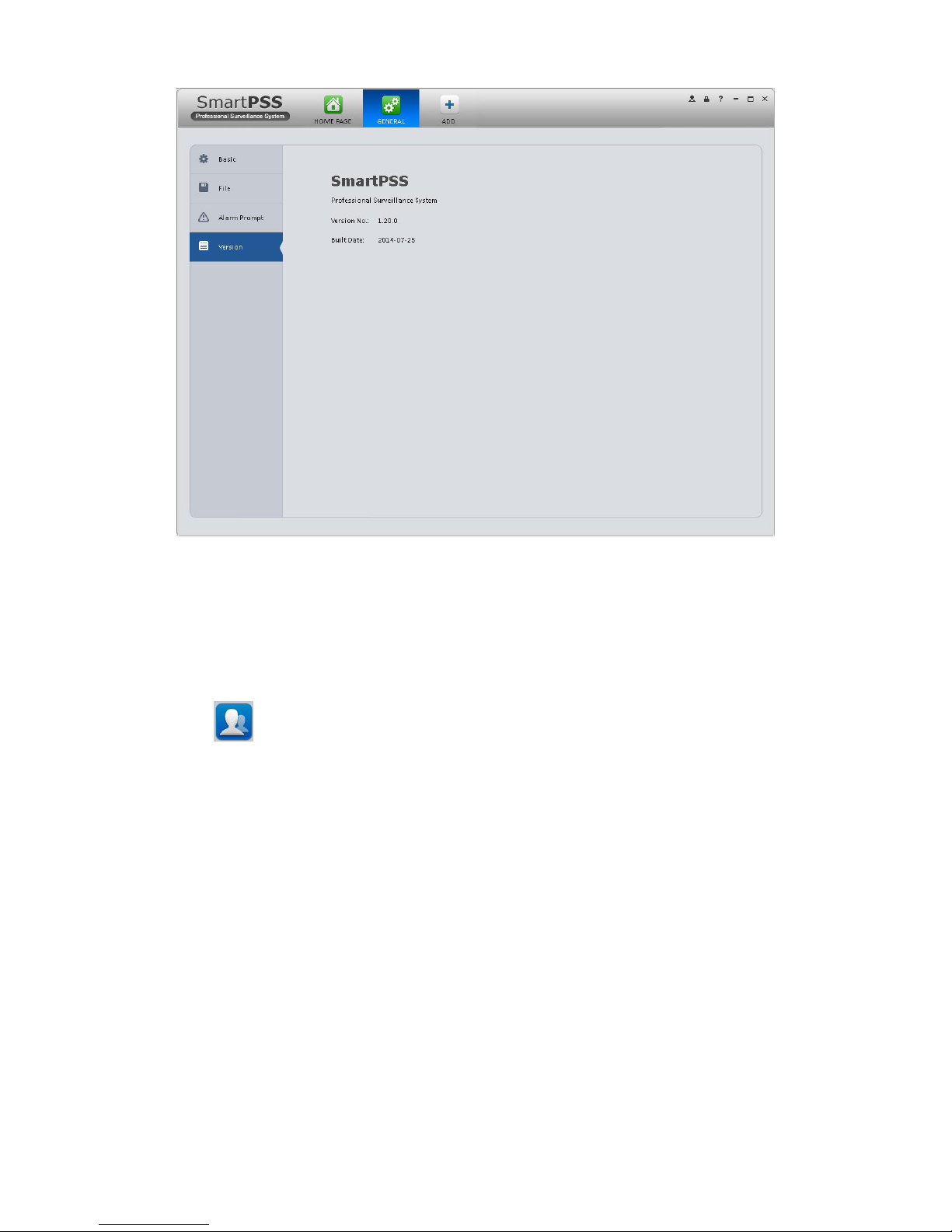
3.3.4 Version
Click the version button; you can go to the following interface. See Figure 3-6.
Here you can view software version information.
Page 16
12
Figure 3-6
3.4 Account
Here you can add, modify or delete a user.
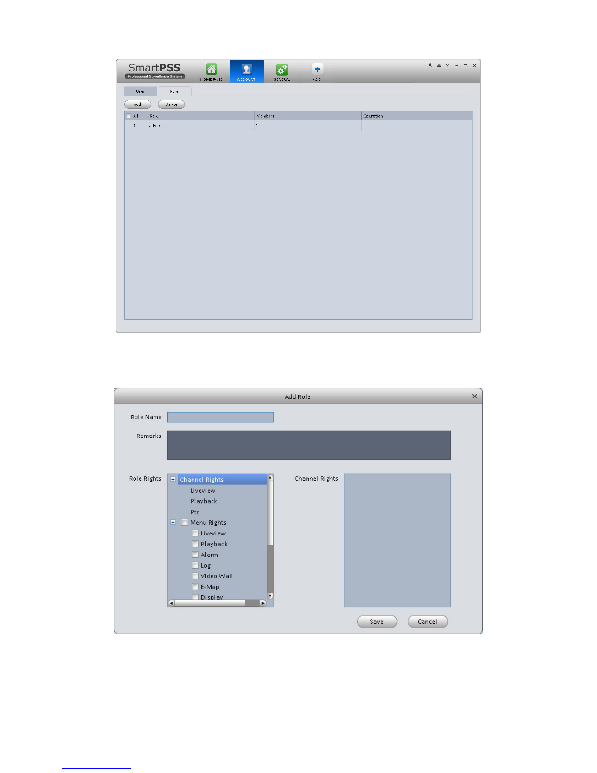
3.4.1 Add role
1) Click in the Settings pane, and then click role button, you can go to the following
interface. See Figure 3-7.
Page 17
13
Figure 3-7
2) Click Add button, the interface is shown as in Figure 3-8.
Figure 3-8
Page 18
14
3) Please input a role name and check the corresponding role rights. You can input some
reference information if necessary.
4) Click Save button.
Tips
Select a role and then click Modify/Delete button to modify or delete a role.
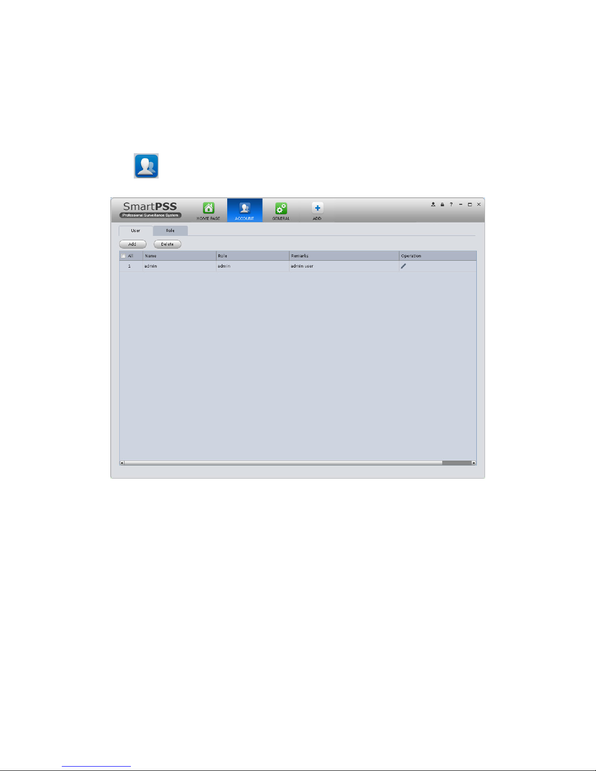
3.4.2 Add user
1) Click in the Settings pane, and then click user button, you can go to the following
interface. See Figure 3-9.
Figure 3-9
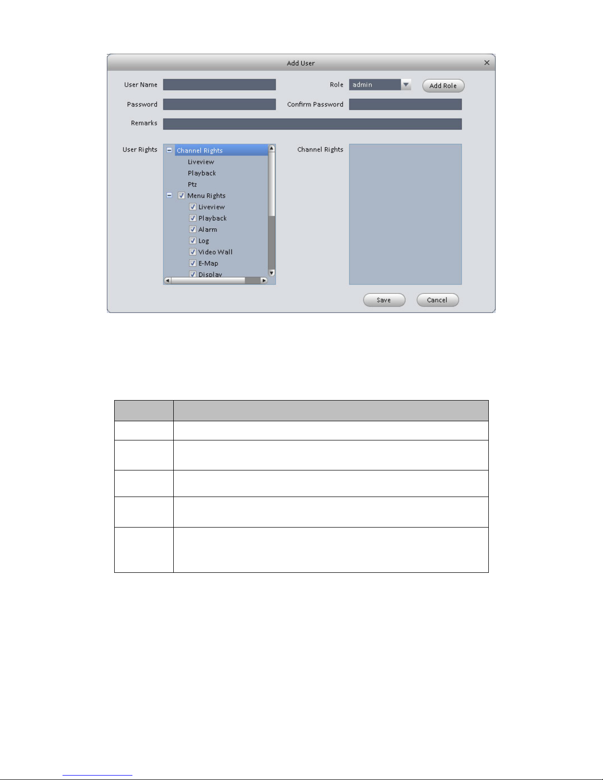
2) Click Add button, you can see system pops up the following interface. See Figure 3-10.
Page 19
15
Figure 3-10
3) Select a role from the dropdown list, input user name, password and confirm password.
Input some description information if necessary. Select rights for the new user.
4) Click Save button to add a new user.
Please refer to the following sheet for detailed information.
Item
Function
User name
Please input user name here.
Role
You can select user role from the dropdown list. Or you can click Add
role button to add a new role.
Password
Please set user password.
Confirm
password
Please input new password again.
User
Rights
Here you can check the box to select corresponding rights for current
user.
If the new user is a manager, system checks all rights by default.
5) Click Save button to add a new user.
Tips
Select a user name and then click Modify/Delete button to modify or delete a user.
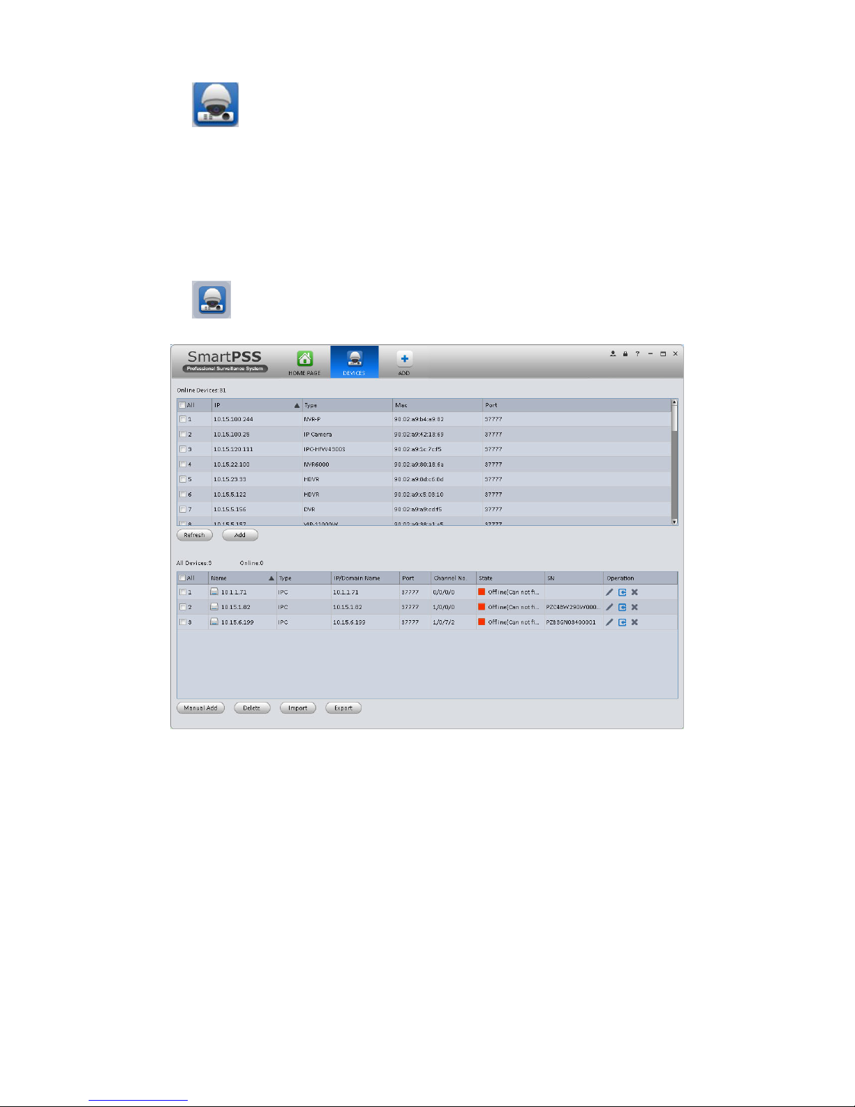
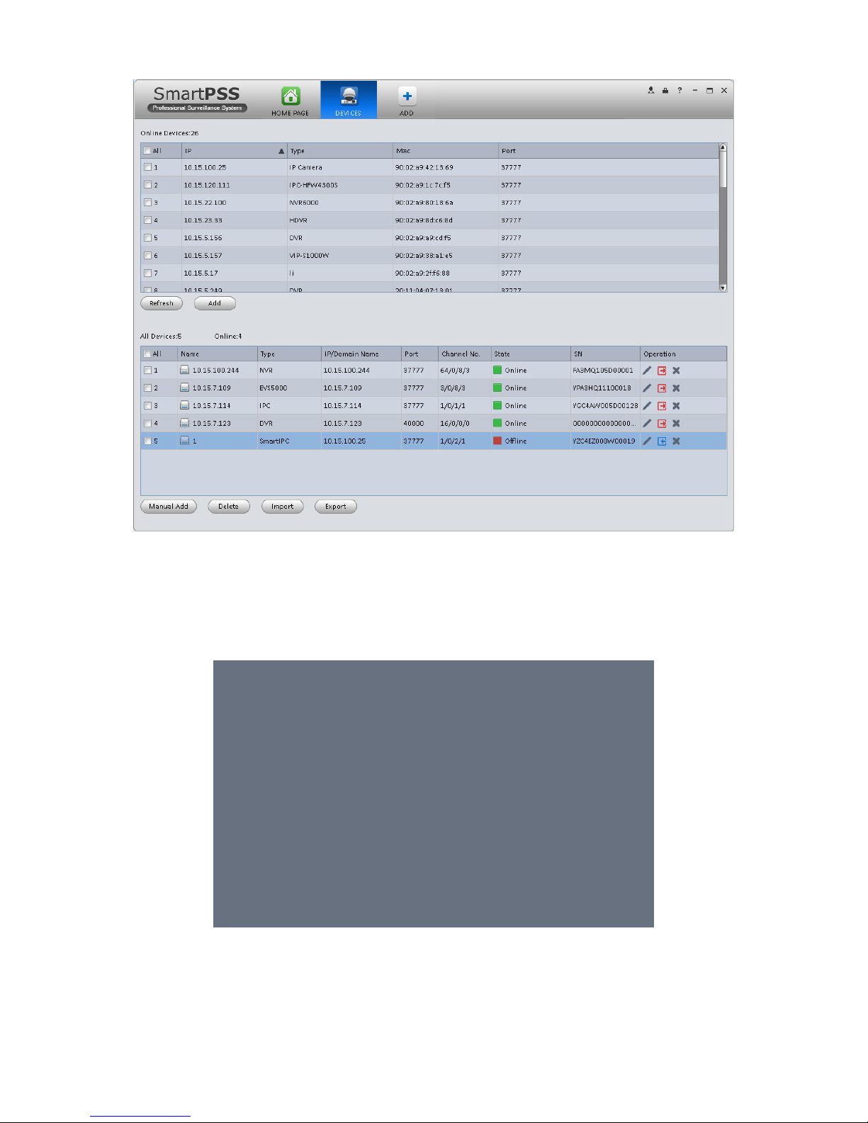
3.5 Device Manager
Here you can add, modify and delete a device. You can also implement device channel group
function.
Auto Add
Page 20
16
1) Click icon. System displays device manager interface.
2) Click Refresh, search device within the LAN.
3) Check device, click Add as auto add device.
Manually Add
You can refer to the steps listed below to add, modify or delete a device manually or
automatically.
1) Click icon in the settings pane, system goes to the device manager interface; you can
see an interface is shown as in Figure 3-11.
Figure 3-11
2) Click Manual Add button, the interface is shown as in Figure 3-12. Please input the
corresponding information and then click Add button.
Page 21

17
Figure 3-12
Please refer to the following sheet for detailed information.
Item
Function
Device name
Please input a device name here.
Register
Mode
By IP/domain and SN.
IP/Domain
name
Device IP address or domain name.
SN
Device SN.
Note:
For P2P device only.
Port
Device IP port.
It is 37777 by default.
Group Name
You can choose one group.
Type
Device type.
User name
The user name you login the device.
Page 22

18
Item
Function
Password
The password you login the device.
3) Config device input info, and click on Get Info. System auto gets device info as in Figure 3-
13.
Figure 3-13
Device SN
Device SN. Read-only.
Video input
Device video input channel amount.
Video output
Device video output channel amount.
Alarm input
Device alarm input channel amount.
Alarm output
Device alarm output channel amount.
4) Click Add. You can click Save and Continue to add next device. Added devices are shown
as in Figure 3-14.
Page 23
19
Figure 3-14
Click Import to batch import local config in .xml format. Or you can import with Easy 4IP account.
See Figure 3-15.
Figure 3-15
Tips
Page 24
20
Select a device in the list, and then:
click to modify, or click to delete it.
Click to login the device manually.
Click to logout the device manually.
Click button and then select save path to save current device list to .xml file.
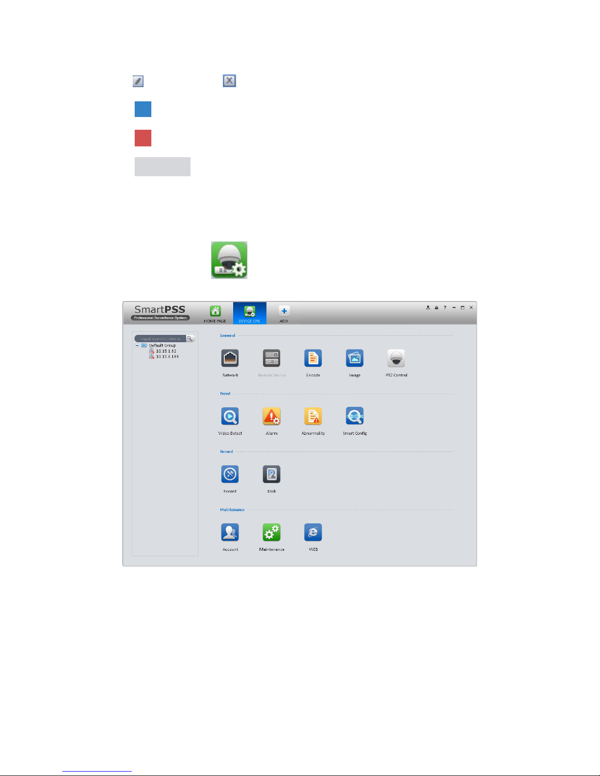
3.6 Signals Manager
After you added a new device, you can go to the signals manager interface to set parameters.
On the main interface, click button in the Settings pane, you can go to the following
interface. See Figure 3-16.
Figure 3-16
3.6.1 General
3.6.1.1 Network
Here is for you to set network information such as TCP/IP, connection, PPPoE, DDNS, IP filter,
SMTP, Multicast, and alarm centre.
3.6.1.1.1 TCP/IP
Page 25
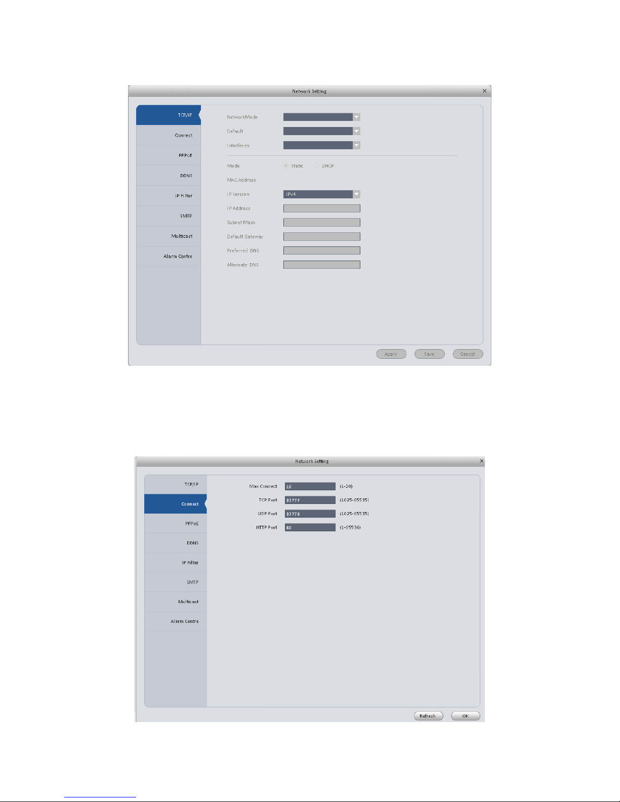
21
Here you can set corresponding parameter when you are using TCP/IP connection. See Figure
3-17.
Figure 3-17
3.6.1.1.2 Connect
Here you can set max login account amount, TCP port, UDP port, HTTP port, RTSP port and etc.
See Figure 3-18.
Figure 3-18
Page 26
22
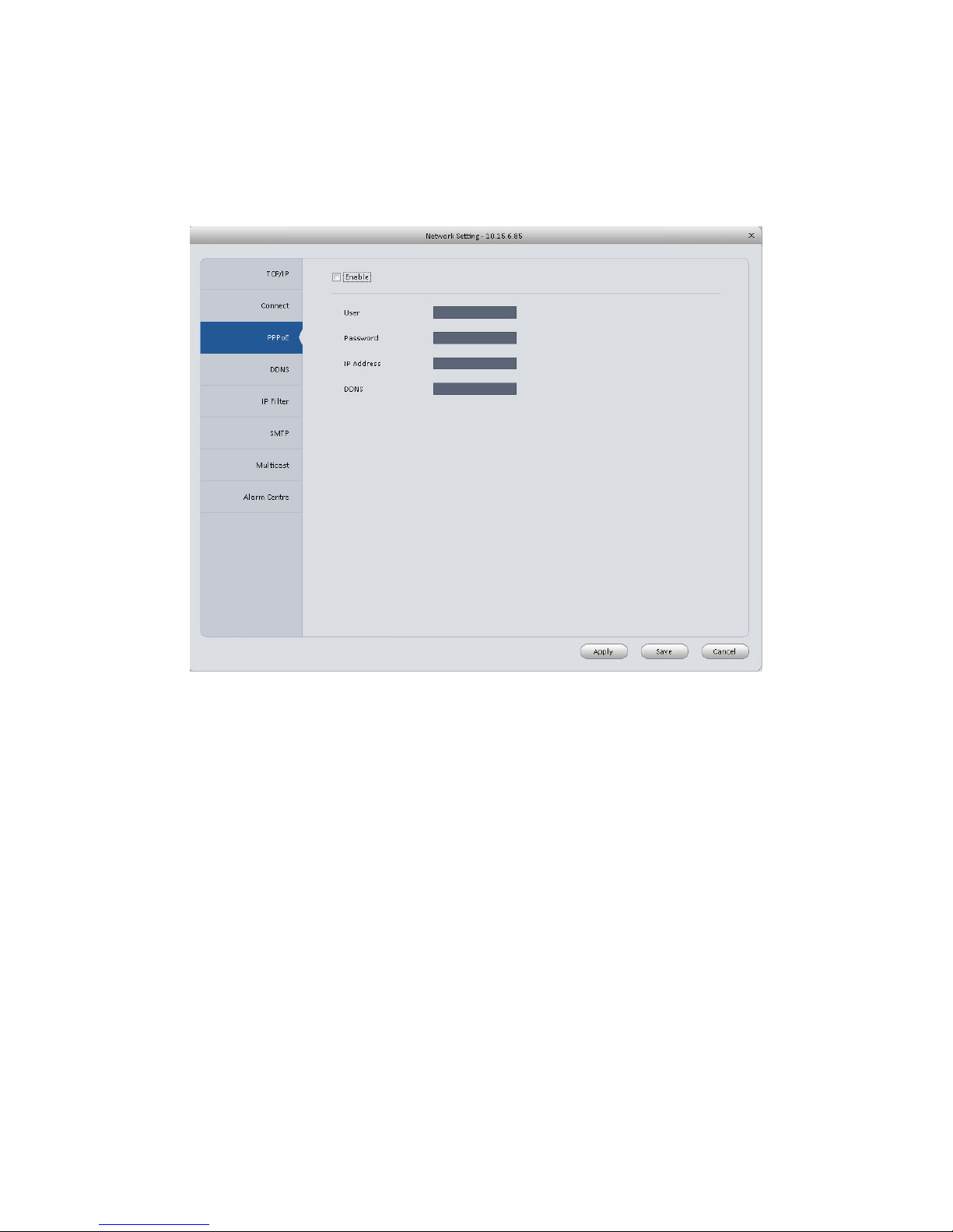
3.6.1.1.3 PPPoE
PPPoE interface is shown as below. See Figure 3-19.
Input “PPPoE name” and “PPPoE password” you get from your ISP (Internet service provider).
Click OK button, you need to restart to activate your configuration.
After rebooting, device will connect to internet automatically. The IP in the PPPoE is the device
dynamic value. You can access this IP to visit the device.
Figure 3-19
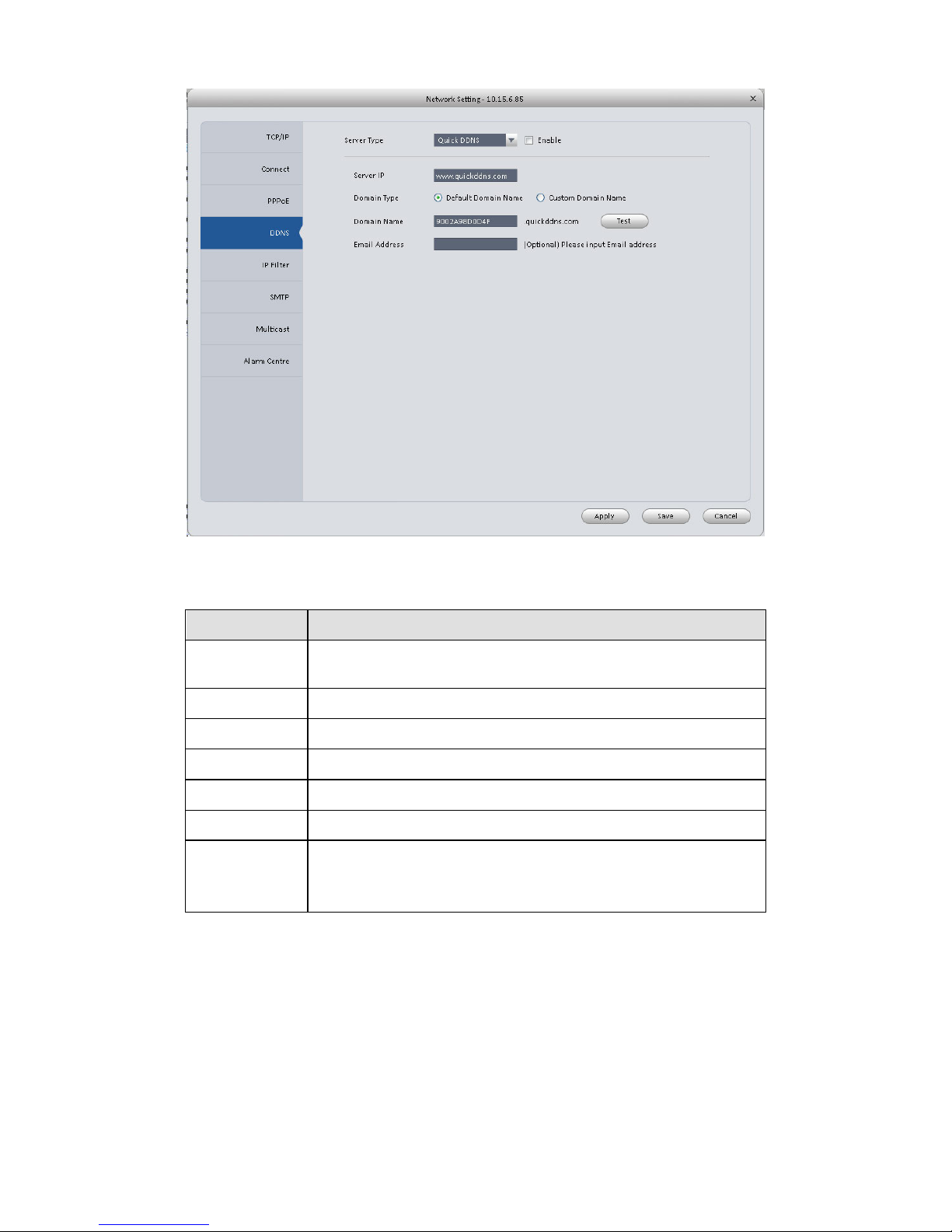
3.6.1.1.4 DDNS
DDNS setup interface is shown as in Figure 3-20.
You need a PC of fixed IP in the internet and there is the DDNS software running in this PC. In
other words, this PC is a DNS (domain name server).
In network DDNS, please select DDNS type and highlight enable item. Then please input your
PPPoE name you get from you IPS and server IP (PC with DDNS). Click OK button and then
reboot system.
Click Ok button, system prompts for rebooting to get all setup activated.
After rebooting, open IE and input as below:
http://(DDNS server IP)/(virtual directory name)/webtest.htm
Page 27
23
Figure 3-20
Please refer to the following sheet for detailed information.
Parameter
Function
Server Type
You can select DDNS protocol from the dropdown list and then
enable DDNS function.
Server IP
DDNS server IP address.
Server Port
DDNS server port.
Domain Name
Your self-defined domain name.
User
The user name you input to log in the server.
Password
The password you input to log in the server.
Update interval
Device sends out alive signal to the server regularly.
You can set interval value between the device and DDNS server
here.
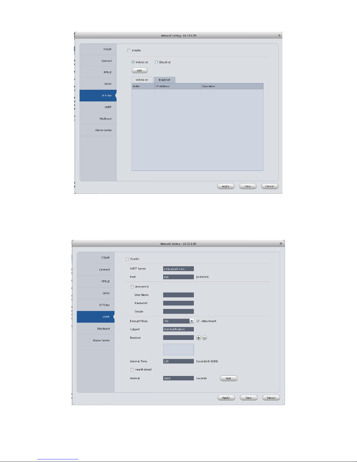
3.6.1.1.5 IP Filter
IP filter interface is shown as in Figure 3-21. You can add IP in the following list.
After you enabled whitelist function, only the IP listed below can access current device.
If you enable blacklist function, the following listed IP addresses can not access current device.
Page 28
24
Figure 3-21
3.6.1.1.6 SMTP (Email)
The SMTP interface is shown as in Figure 3-22. Here you can set email receiver, encryption
mode, send out interval and etc.
Figure 3-22
Page 29

25
Please refer to the following sheet for detailed information.
Parameter
Function
Enable
Please check the box here to enable email function.
SMTP Server
Input server address and then enable this function.
Port
Default value is 25. You can modify it if necessary.
Anonymity
For the server supports the anonymity function. You can auto
login anonymously. You do not need to input the user name,
password and the sender information.
User Name
The user name of the sender email account.
Password
The password of sender email account.
Sender
Sender email address.
Encryption mode
System supports SSL/NONE/TLS.
Subject
Input email subject here.
Attachment
System can send out the email of the snapshot picture once
you check the box here.
Receiver
Input receiver email address here. Max three addresses.
Interval
The send interval ranges from 0 to 3600 seconds. 0 means
there is no interval.
Please note system will not send out the email immediately
when the alarm occurs. When the alarm, motion detection or
the abnormity event activates the email, system sends out the
email according to the interval you specified here. This
function is very useful when there are too many emails
activated by the abnormity events, which may result in heavy
load for the email server.
Health mail
enable
Please check the box here to enable this function.
Health mail
interval
This function allows the system to send out the test email to
check the connection is OK or not.
Please check the box to enable this function and then set the
corresponding interval.
System can send out the email regularly as you set here.
Test
The system will automatically sent out an email once to test
the connection is OK or not .Before the email test, please
save the email setup information.
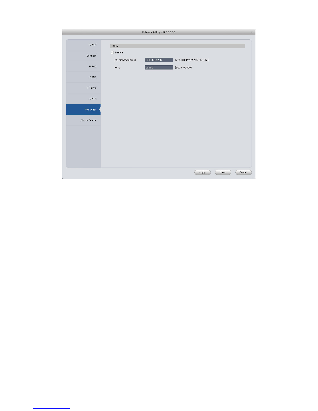
3.6.1.1.7 Multicast
The multicast interface is shown as in Figure 3-23.
Multicast is a transmission mode of data packet. When there is multiple-host to receive the same
data packet, multiple-cast is the best option to reduce the broad width and the CPU load. The
source host can just send out one data to transit. This function also depends on the relationship
of the group member and group of the outer.
Page 30
26
Figure 3-23
3.6.1.1.8 Alarm Server
The alarm centre interface is shown as below. See Figure 3-24.
This interface is reserved for you to develop. System can upload alarm signal to the alarm centre
when local alarm occurs.
Before you use alarm centre, please set server IP, port and etc. When an alarm occurs, system
can send out data as the protocol defined, so the client-end can get the data.
Page 31

27
Figure 3-24
3.6.1.2 Remote
Here you can add remote device manually or automatically. See Figure 3-25.
Figure 3-25
Page 32
28
Click Search device button, system can list all the devices on the same IP section. Select a
device and then click Add button; you can add a remote device.
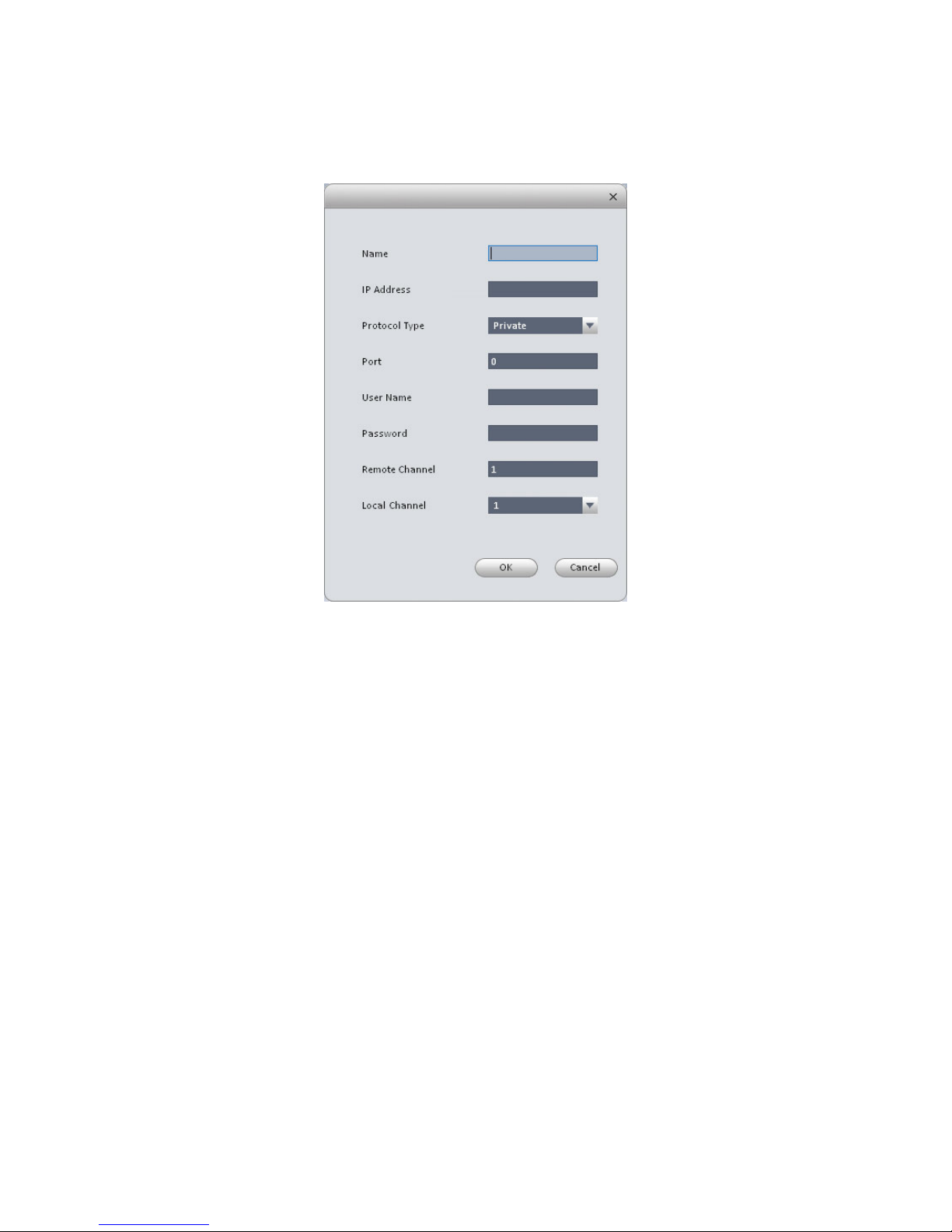
Click Manual add button, System pops up the following dialogue box. See Figure 3-26. Please
input the corresponding information and then click OK button to add a remote device.
Figure 3-26
3.6.1.3 Encode
3.6.1.3.1 Audio/Video
The interface is shown as below. See Figure 3-27. Here you can set audio/video bit stream.
Page 33

29
Figure 3-27
Please refer to the following sheet for detailed information.
Parameter
Function
Video enable
Check the box here to enable extra stream video. This item is
enabled by default.
Stream type
It includes main stream, motion stream and alarm stream. You
can select different encode frame rates form different recorded
events.
Encode mode
It is to set audio/video encode mode. Default setup is H.264.
Resolution
System supports various resolutions, you can select from the
dropdown list.
FPS
PAL:1~25f/s;NTSC:1~30f/s.
Bit stream
In VBR mode, it is the max value of the bit stream. In the CBR
mode, it is a fixed value.
Ref Stream
According to selected encode mode, resolution, display bit
stream. (range)
Iframes
Interval between key frames.
Quality
You can select from the dropdown list.
Audio encode
mode
Check the box here to enable audio function and select encode
type from the dropdown list.
Page 34

30
Watermark
enable
/watermark
character
This function allows you to verify the video is tampered or not.
Here you can select watermark bit stream, watermark mode
and watermark character.
Copy
Click it to copy current setup to other channel(s).
3.6.1.3.2 Snapshot
The snapshot interface is shown as below. See Figure 3-28.
Figure 3-28
Please refer to the following sheet for detailed information.
Parameter
Function
Snapshot type
There are three modes.
Regular: It enables snapshot function as you set on the
snapshot plan.
MD: It enables snapshot function when motion detect
occurs.
Alarm: It enables snapshot function when an alarm occurs.
Image size
It is the same with the resolution of the main stream.
Quality
It is to set the image quality.
Interval
It is to set snapshot frequency.
Copy
Click it; you can copy current channel setup to other
channel(s).
3.6.1.3.3 Overlay
Here is for you to overlay information on the video. See Figure 3-29.
Page 35

31
Figure 3-29
Please refer to the following sheet for detailed information.
Parameter
Function
Channel Name
Set channel name.
Area-overlay
There are two types: Local liveview/network monitor.
Local liveview: It is to shield the corresponding video under
local liveview mode.
Network monitor: It is to shield the corresponding video under
network monitor mode.
Click button to set a zone.
Channel display
You can enable this function so that system overlays channel
information in video window.
Please input channel name here.
You can use the mouse to drag the channel title position.
Time display
You can enable this function so that system overlays time
information in video window.
You can use the mouse to drag the time title position.
You can view time title on the live video of the WEB or the
playback video.
Date format
Select date format from the dropdown list if you want to overlay
date information.
Time format
Select date format from the dropdown list if you want to overlay
time information.
Copy
Click it; you can copy current channel setup to other
Page 36

32
channel(s).
3.6.1.4 Image
Here you can set camera property. See Figure 3-30.
Figure 3-30
Please refer to the following sheet for detailed information.
Parameter
Function
Color mode
It is to set color mode.
Hue
It is to set color hue.
Brightness
It is to adjust color whole brightness. The large the value is, the bright
the video is and vice versa.
When you set, the dark pane and the bright pane of the video can be
increased or decreased accordingly at the same time.
Contrast
It is to set video contrast. The large the value is, the big the contrast is,
vice, versa.
Saturation
It is to set color saturation. The larger the value is, the strong the color
is and vice versa.
3.6.1.5 PTZ Control
It is for you to set PTZ parameters. See Figure 3-31.
Page 37

33
Figure 3-31
Please refer to the following sheet for detailed information.
Parameter
Function
Protocol
Select the corresponding dome protocol such as PELCOD.
Address
Set corresponding dome address. Default value is 1. Please note
your setup here shall comply with your dome address; otherwise
you can not control the speed dome.
Baud
Rate
Select the dome baud rate. Please set according to the speed dome
dial switch setup.
Data Bit
Please set according to the speed dome dial switch setup.
Stop bit
Please set according to the speed dome dial switch setup.
Parity
Please set according to the speed dome dial switch setup.
3.6.2 Event
3.6.2.1 Video Detect
The video detect includes three types:
Motion detect: Through analyze video, system can enable motion detect alarm when it
detects any moving signal that reaches the sensitivity threshold you set here.
Video loss: This function allows you to be informed when video loss phenomenon
occurred. You can enable alarm output channel and then enable show message function.
Camera masking: When someone viciously masks the lens, or the output video is in one-
color due to the environments light change, the system can alert you to guarantee video
continuity.
Page 38

34
Here we use motion detect interface as an example. See Figure 3-32.
Figure 3-32
Figure 3-33
Page 39

35
Figure 3-34
Figure 3-35
Page 40

36
Figure 3-36
Figure 3-37
Please refer to the following sheet for detailed information.
Parameter
Function
Enable
You need to check the box to enable motion detection function.
Page 41

37
Parameter
Function
Arm/disarm
Period
Motion detection function becomes activated in the specified
periods. See Figure 3-33.
There are six periods in one day. You can click to set (Figure
3-34) or use mouse to draw the corresponding period on the time
bar directly (Figure 3-35).
Click OK button, system goes back to motion detection interface,
please click OK button to exit.
Anti-dither
System only memorizes one event during the anti-dither period.
The value ranges from 5s to 100s.
Sensitivity
There are 10 levels. The sixth level has the highest sensitivity.
Zone
You can click this button to set motion detection zone. The
interface is shown as in Figure 3-36. Do remember clicking OK
button to save your motion detection zone setup.
Record
channel
If you select this parameter, then you perform motion detection
alarm recording to this channel.
Please note you need to select auto record in Record-> record
control
Record Delay
System can delay the record for specified time after alarm ended.
Upload To
Cloud
Check if to upload to Cloud.
Alarm output
Enable alarm activation function. You need to select alarm output
port so that system can activate corresponding alarm device when
an alarm occurs.
Output delay
System can delay the alarm output for specified time after an
alarm ended.
Show
message
System can pop up a message to alarm you in the local host
screen if you enabled this function.
Buzzer
Check the box here to enable this function. The buzzer beeps
when an alarm occurs.
Alarm upload
System can upload the alarm signal to the centre (Including alarm
centre.
Message
When 3G network connection is OK, system can send out a
message when motion detect occurs.
Send Email
If you enabled this function, System can send out an email to alert
you when an alarm occurs.
SMS
If you enabled this function, System can send out a message to
specified phone to alert you when an alarm occurs.
Tour
You need to check the box here to enable this function. System
begins 1-wiindow or multiple-window tour display among the
channel(s) you set to record when an alarm occurs.
PTZ
Activation
Here you can set PTZ movement when alarm occurs. See Figure
3-37.
Video Matrix
This function is for motion detect only. Check the box here to
Page 42
38
Parameter
Function
enable video matrix function.
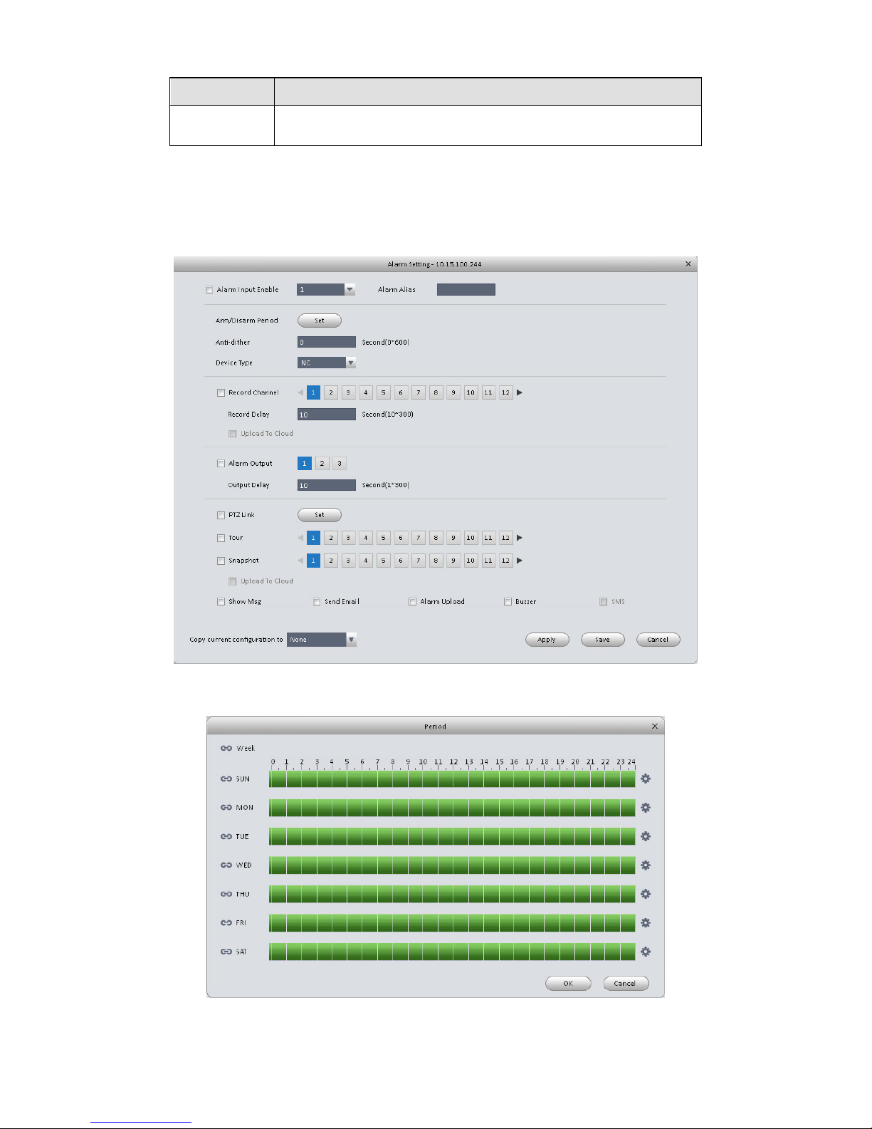
3.6.2.2 Alarm
Before operation, please make sure you have properly connected alarm devices such as
buzzer. The input mode includes local alarm and network alarm.
The local alarm interface is shown as in Figure 3-38.
Figure 3-38
Figure 3-39
Page 43

39
Figure 3-40
Figure 3-41
Figure 3-42
Page 44

40
Please refer to the following sheet for detailed information.
Parameter
Function
Enable
You need to check the box to enable this function.
Please select a channel from the dropdown list.
Arm/disarm Period
This function becomes activated in the specified periods.
There are six periods in one day. See Figure 3-39.
There are six periods in one day. You can click to set
(Figure 3-40) or use mouse to draw the corresponding
period on the time bar directly (Figure 3-41).
Click OK button, system goes back to alarm interface,
please click OK button to exit.
Anti-dither
System only memorizes one event during the anti-dither
period.
Device (Sensor)
type
There are two options: NO/NC.
Record Delay
System can delay the record for specified time after alarm
ended.
Output delay
System can delay the alarm output for specified time after
an alarm ended.
Record channel
If you select this parameter, then you perform local alarm
recording to this channel.
Please note you need to select auto record in
Record-> record control
Record Delay
Means when alarm link ends, record delay for a certain
period of time before stop.
Alarm output
Enable alarm activation function. You need to select alarm
output port so that system can activate corresponding
alarm device when an alarm occurs.
Video matrix
Check the box here to enable video matrix function.
Show message
System can pop up a message to alarm you in the local
host screen if you enabled this function.
Buzzer
Check the box here to enable this function. The buzzer
beeps when an alarm occurs.
Alarm upload
System can upload the alarm signal to the centre
(Including alarm centre.
Send Email
If you enabled this function, System can send out an
email to alert you when an alarm occurs.
SMS
If you enabled this function, System can send out a
message to specified phone to alert you when an alarm
occurs.
Tour
You need to check the box here to enable this function.
Snapshot
If you select this parameter, then the channel is config
with alarm snapshot function.
PTZ Activation
Here you can set PTZ movement when alarm occurs.
Page 45

41
Parameter
Function
Such as go to preset X. See Figure 3-42.
3.6.2.3 Abnormality
It includes six statuses: No device, no space, device error, net offline, IP conflict and MAC
conflict. See Figure 3-43 through Figure 3-48.
Figure 3-43
Page 46

42
Figure 3-44
Figure 3-45
Page 47

43
Figure 3-46
Figure 3-47
Page 48

44
Figure 3-48
Please refer to the following sheet for detailed information.
Parameter
Function
Enable
Check the box here to enable selected function.
Alarm
Output
Please select corresponding alarm output channel when an alarm
occurs. You need to check the box to enable this function.
Output
delay
The alarm output can delay for the specified time after an alarm stops.
Show
message
System can pop up a message to alarm you in the local host screen if
you enabled this function.
Alarm
upload
System can upload the alarm signal to the centre (Including alarm
centre.
Send
Email
If you enabled this function, System can send out an email to alert you
when an alarm occurs.
Buzzer
Check the box here to enable this function. The buzzer beeps when an
alarm occurs.
SMS
If you enabled this function, System can send out a message to
specified phone to alert you when an alarm occurs.
3.6.2.4 Smart Config
Page 49

45
SmartPSS supports to add SmartIPC and config added intelligent device, including audio
detection config and face recognition. After config is complete, you can go to live interface for
preview. Please refer to Ch 4.1.1.
See Figure 3-49.
Figure 3-49
Parameter
Note
Abnormal
Detect
If enable this parameter, then audio detection alarm is enabled.
Mutation
Detect
May config sensitivity and mutation threshold.
If select this parameter, then mutation detect is enabled.
Sensitivity: 1-100 level adjustable. The smaller the value is, the more input sound
volume change exceeds constant environmental sound and is judged as abnormal
audio. User shall adjust according to actual environment.
Mutation threshold:1-100 level adjustable. It is used to set filter of environmental
sound intensity. If environmental noise is high, then you shall set this value high.
Please set and adjust according to actual environment.
Page 50

46
Parameter
Note
Arm/Disarm
Period
Set alarm arm/disarm period.
Click set pop up Arm/Disarm Period box for setup.
Anti-dither
Means only record one motion detection event within the period. Value range 0s~
100s.
Record
Channel
If select the parameter, then alarm record the channel.
Go to “Record >Record Control” and select auto record.
Record Delay
Means when alarm link is end, motion detection record will remain for a period of
time before stop.
Alarm Output
If select the parameter, then enable alarm link output port, so when alarm occurs, it
can link corresponding alarm output device.
Output Delay
Means when alarm link ends, alarm will remain for a period of time before stop.
Capture
If select this parameter, then select this parameter, then this channel config motion
detection snapshot function.
Video Matrix
If select this parameter, then enable matrix function.
Send EMAIL
If select this parameter, then when alarm occurs, it send Email to user.
Alarm Upload
If select this parameter, then when alarms occurs, alarm will be sent to center.
SMS
If select this parameter, then when alarm occurs, user will receive SMS.
Face Detect is shown in Figure 3-50.
Page 51

47
Figure 3-50
Parameter
Note
Enable
If select this parameter, it will link alarm.
Arm/Disarm
Period
Set alarm arm/disarm period.
Click setup to pop up arm/disarm period box.
Dynamic
Track
If select this parameter, then it enable dynamic trick.
Record
Channel
If select this parameter, then the channel has record of alarm.
Go to “Record > Record Control” and select “auto” record.
Record Delay
Means when alarm link ends, motion detection delays for a period of time.
Alarm Output
If select this parameter, then enable alarm link output port, when alarm occurs, may
link alarm output device.
Output Delay
Means when alarm link ends, alarm delays for a period of time.
Capture
If select this parameter, then it configures dynamic snapshot function for this
channel.
Page 52

48
Parameter
Note
Send EMAIL
If select this parameter, then when alarm occurs, it send Email to user.
Alarm Upload
If select this parameter, then when alarms occurs, alarm will be sent to center.
SMS
If select this parameter, then when alarm occurs, user will receive SMS.
3.6.3 Record/Storage
3.6.3.1 Schedule
Record setup has record plan and record control.
Record plan (schedule): Record during set period.
Record control: Select mode of record.
You can set the corresponding period to enable schedule record function. You can follow the
steps listed below to set schedule record function.
1) Click Schedule button, you can go to the following interface. See Figure 3-51.
Page 53

49
Page 54

50
Figure 3-51
2) Click button after corresponding date, you can see an interface shown as below. See
Figure 3-52.
Page 55

51
Figure 3-52
3) Set record period and check the box to select record type. Click OK button, now you can see
an interface shown as in Figure 3-53.
Figure 3-53
You can view the current time period setup from the color bar.
Green color stands for the general record.
Yellow color stands for the motion detect record.
Red color stands for the alarm record.
Blue color stands for MD and alarm record.
Tips
Choose the channel you want, then click save button to copy current setup
3.6.3.1.1 Record Control
It is for you to set record control mode. See Figure 3-54.
Page 56

52
Figure 3-54
Please refer to the following sheet for detailed information.
Parameter
Function
Pre-record
Please input pre-record time here.
Main stream
It is to set main stream record mode. It includes:
Schedule/manual/stop.
Sub stream
It is to set sub stream record mode. It includes:
Schedule/manual/stop.
3.6.3.2 Disk
3.6.3.2.1 Local Store
The local interface is shown as in Figure 3-55. Here you can save data to local SD card or HDD.
Page 57

53
Figure 3-55
3.6.3.2.2 Remote store
It is for you to upload data to a PC via FTP. See Figure 3-56.
Figure 3-56
3.6.4 Maintenance
Page 58

54
3.6.4.1 Account
Here you can add/modify/delete a group or add/modify/delete a user. System default user group
is admin/user. System default user is admin/888888/666666.
Click Account button in Signals interface and then click Role button. See Figure 3-57.
Figure 3-57
Click Add button, you can see system pops up the following interface. See Figure 3-58. Please
input a group name and then select corresponding rights, input some note information for your
reference if necessary. Click OK button to exit.
Figure 3-58
Page 59

55
Go to the User interface, here you can add/remove user and modify user name. See Figure 3-59.
Figure 3-59
Click Add button, you can see the following interface. See Figure 3-60. Please input user name,
password, and select a group from the dropdown list. Select corresponding rights and then click
OK button.
Tips
If you want to multiple users to use this account login at the same time, you need to check the
box to select reusable function.
Page 60

56
Figure 3-60
3.6.4.2 Maintenance
3.6.4.2.1 Host
Here you can set system time, date format, record period and etc. See Figure 3-61.
Page 61

57
Figure 3-61
Please refer to the following sheet for detailed information.
Parameter
Function
Device
name
It is to set device name.
Device No.
When you are using one remote control to manage multiple devices,
you can give a serial numbers to the device.
Before the operation, please make sure you have clicked address
button on the remote control and input a number for current device.
Language
You can select the language from the dropdown list.
Please note the device needs to reboot to get the modification
activated.
Video
Standard
This is to display video standard such as PAL.
HDD full
Here is for you to select working mode when hard disk is full. There
are two options: stop recording or rewrite.
If current working HDD is overwritten or the current HDD is full
while the next HDD is no empty, then system stops recording,
If the current HDD is full and then next HDD is not empty, then
system overwrites the previous files.
Pack
duration
Here is for you to specify record duration.
3.6.4.2.2 Date&Time
The date and time interface is shown as in Figure 3-62.
Page 62

58
Figure 3-62
Please refer to the following sheet for detailed information.
Parameter
Function
Date format
Here you can select date format from the dropdown list.
Time
Format
There are two options: 24-H and 12-H.
Time zone
The time zone of the device.
System
time
It is to set system time. It becomes valid after you set.
Sync PC
You can click this button to save the system time as your PC current
time.
DST enable
Here you can set day night save time begin time and end time. You
can set according to the date format or according to the week
format.
NTP
You can check the box to enable NTP function.
NTP server
You can set the time server address.
Port
It is to set the time server port.
Update
period
It is to set the sync periods between the device and the time server.
3.6.4.2.3 RS232
The RS232 interface is shown as in Figure 3-63.
Page 63

59
Figure 3-63
Please refer to the following sheet for detailed information.
Parameter
Function
COM
You can select from the dropdown list.
Function
There are various devices for you to select.
Console is for you to use the COM or mini-end software to
upgrade or debug the program.
The control keyboard is for you to control the device via the
special keyboard.
Transparent COM (adapter) is to connect to the PC to transfer
data directly.
Protocol COM is for card overlay function.
Network keyboard is for you to use the special keyboard to
control the device.
Baud Rate
Default setup is 115200.
Data Bit
Default setup is 8.
Stop bit
Default setup is 1.
Parity
Default setup is none.
3.6.4.2.4 Auto Maintenance
Here you can set auto-reboot time and auto-delete old files setup. You can set to delete the files
for the specified days. See Figure 3-64.
Page 64

60
Figure 3-64
3.6.4.2.5 Version
Version interface is shown as below. See Figure 3-65.
Figure 3-65
Page 65

61
3.6.4.3 WEB
Click it to go to the WEB of the device. See Figure 3-66. The following figure is for reference only.
Figure 3-66
3.7 Alarm Setup
3.7.1 Set Alarm Scheme
You can follow the steps listed below to set an alarm scheme.
1) Click the icon in the Settings pane, you can go to alarm configuration interface. See
Figure 3-67.
Page 66

62
Figure 3-67
2) Set alarm sources.
a) Click button in Figure 3-67 , system goes to alarm sources setup
interface. See Figure 3-68.
3) Here you can input a scheme name and some reference information. select the alarm type
from the dropdown list.
Page 67

63
a) Check the box to select a channel you want to set alarm scheme on the left pane; you can add
it to the list on the right pane.
Figure 3-68
b) Click Alarm Link on the left pane or click next button in Figure 3-68 , you can go to the
following interface. Please check the trigger channel in Figure 3-69 and alarm output
channel in Figure 3-70.
Page 68

64
Figure 3-69
Figure 3-70
c) Click Period button on the left pane or click next button in Figure 3-69, you can go to the
following interface. See Figure 3-71.
Page 69

65
Figure 3-71
Click after a date to set alarm activation period. There are six periods in one day. See
Figure 3-72. Click OK button to exit.
Figure 3-72
Page 70

66
d) Click OK button, you can view the scheme information on the alarm setup interface. See
Figure 3-73.
Figure 3-73
3.7.2 Enable/Disable/Export Scheme
After you added a scheme, you can view the following contents for operation information.
: Delete current scheme.
: Disable current scheme.
: Enable current scheme.
: Add scheme.
: Select one or more scheme(s) and then click this button to delete.
: Import scheme information.
: Export scheme informaiton.
3.8 Video Wall Configuration
This function allows you to output video to the video wall. Please follow the steps listed below.
1) Click , system goes to video wall setup interface. See Figure 3-74.
Page 71

67
Figure 3-74
2) Config video wall.
a) Enter video wall name and description.
b) Click below, select layout as 1*1, 2*2, 3*3, 4*4 or M*M.
Click screen to draw video wall physical layout, see Figure 3-71.
Page 72

68
Figure 3-75
Note
Use Ctrl+left click mouse to select several screens, right click mouse to select splicing or
click , you can combine several screens to a splicing screen. Right click mouse, select
unbind splicing or click , you can cancel splicing.
Select a screen and right click to select rename or delete, you can rename screen name or
delete a screen. Click , you can delete all screens.
c) Click Next button, you can go to video wall input binding interface.
3) Binding decoder channel
Select a decoder channel and then drag it to the corresponding screen of the video wall. See
Figure 3-72.
Page 73

69
Figure 3-76
Note:
When a screen binds M30, you need to splice physical layout , otherwise you cannot bind.
4) Check the box to enable setup immediately and then click Finish button, you can see an
interface shown as in Figure 3-77.
Page 74

70
Figure 3-77
In Figure 3-77, double click a video wall, or select a video wall and then click Modify button ,
you can change its setup. You can also click Delete button or to remove. Click , you can
change video wall on/off setup.
3.9 Tour &Task
It is to realize monitor tour among each window. Please follow the steps listed below to set.
Click icon in the Settings pane, you can go to monitor tour interface. See Figure
3-78.
Page 75

71
Figure 3-78
Click button to add task interface. See Figure 3-81.
Input task name, stay time.
Click at the bottom of the
interface to select window amount.
Drag channel(s) on the right pane to the windows on the left pane. See Figure 3-79.
Page 76

72
Figure 3-79
Click button to save current setup. See Figure 3-80.
Figure 3-80
Tips
Click to save current task setup and add more tasks at the same time.
In Figure 3-80, you can check the enable button to open current scheme. Or you can go to
the main interface and then click Liveview button ( ) to go to the following interface.
See Figure 3-81. Click at the bottom of the interface to enable the scheme.
Page 77

73
Figure 3-81
3.10 PC-NVR
Important
Before you use this function, please make sure you have installed PC-NVR and the PC-NVR
applications are running now!
This function allows you to storage record file on the PC to effectively use wideband. You can
add, modify or delete PC-NVR and set PC-NVR parameter. Please follow the steps listed below.
1) Click icon in the Settings pane, you can go the PC-NVR interface. See Figure 3-82.
Page 78

74
Figure 3-82
2) Remote device
a) Click button, you can see an interface shown as in Figure 3-83. Here you can
add channels.
Page 79

75
Figure 3-83
b) Please select a device and then check the record channels
c) Click Save button.
3) Disk manager
SmartPSS support disk allocation management of PC-NVR.
Note: Before allocation, make sure the disk has at least 7G in free space.
a) In Figure 3-82, click disk manager button on the left pane, you can go to the setup
interface.
b) You can select saved disk and input the space then click . See Figure 3-84.
Page 80

76
Figure 3-84
4) Add record plan
a) In Figure 3-82, click Record Plan button on the left pane. And then select a channel from
the dropdown list and then click button . You can go to the following interface. See
Figure 3-85.
Page 81

77
Figure 3-85
b) Please set period information and type.
c) Please set the corresponding time.
d) Click OK button. You can see an interface shown as in Figure 3-86.
Figure 3-86
Page 82

78
e) Click Save.
Tips
After you complete setup for one channel, you can click Dropdown in Figure 3-86 to copy current
setup to other channel(s).
5) View version.
Page 83

Page 84

80
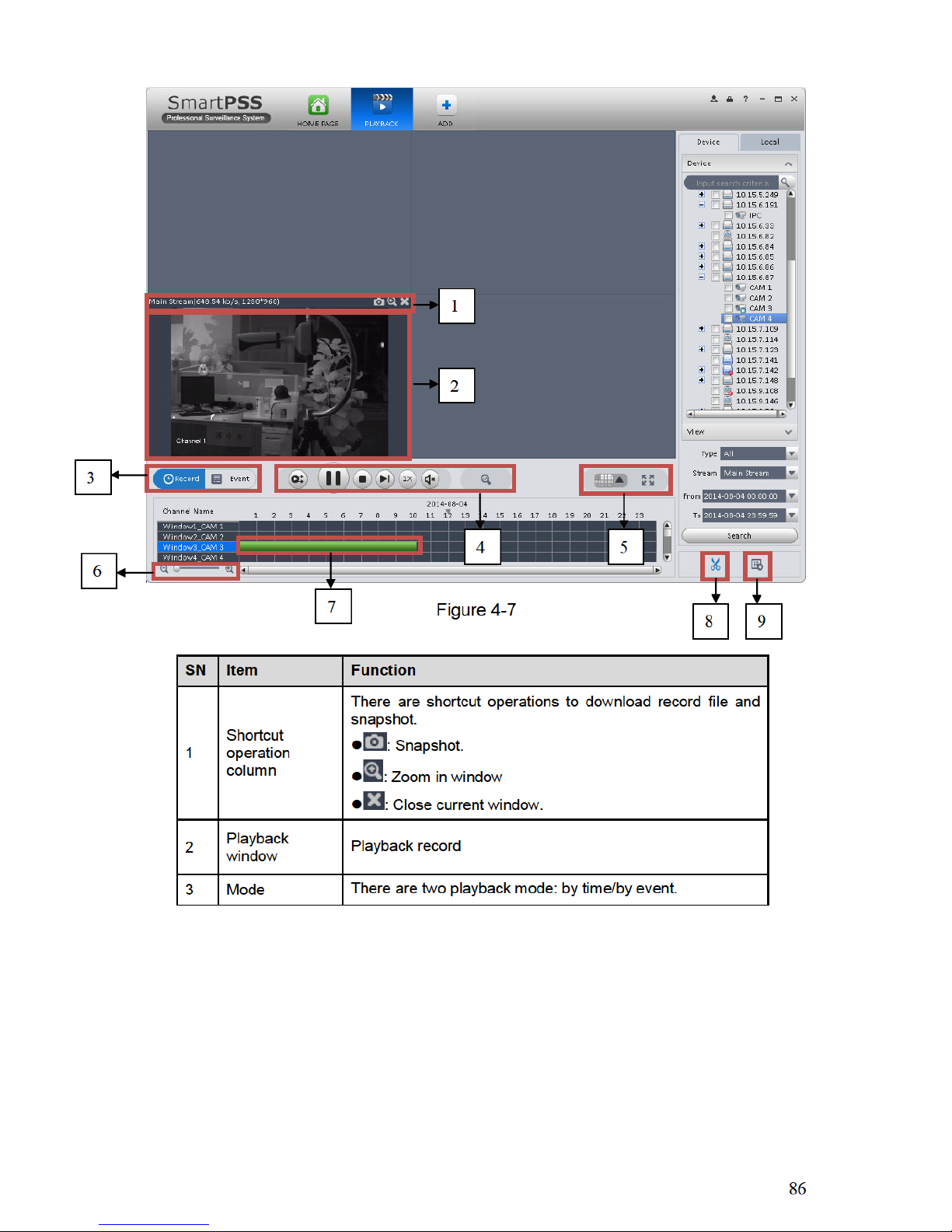
SN
Item
Function
1
Bit stream
information
and
shortcut
operation
menu
Please refer to the following contents for detailed information.
: Enable/disable local record.
: Snapshot.
: Enable/disable audio.
: Enable/disable bidirectional talk.
: Instant playback.
: Digital zoom
: Close current window.
2
Video
window
Real-time video
3
Window
split mode
: It is to set
1-wind to 64-window mode.
: Select a window and then click this button to custmoze its
setup.
: Adjust video scale.
: Full screen.
4
Intelligent
button
:Save current liveview as image. You can view under View.
:Enable tour plan. Refer to Ch 3.9.
:Close tour plan.
:Intelligent alarm. Intelligent device connection, display this
button, meaning device supports intellgient alarm.
:Face recognition. Intelligent device connection, display this
button, meaning device supports face recognition.
5
PTZ
It is for PTZ dome camera or fisheye camera series product only.
Here you can set camera direction, zoom in, zoom out, iris and
etc.
Click advanced button to set preset, tour, aux function and so on.
6
Device list
Display device group and the corresponding channel.
Here you can create a new group and drag a device to it.
Right click a channel, you can select main stream/sub stream or
quickly go to the device setup interface.
Select a liveview window, double click a device channel on the right pane to open the video.
Double click a group name; you can open all channels under current group. Right click device
channel, you can switch between main stream/extra stream.
Right click liveview window, you can see an interface shown as in Figure 4-2.
Page 85

81
Figure 4-2
Please refer to the following sheet for detailed information.
Item
Function
Close video
Click it to close current window.
Close all video
Click it to close all windows.
Start audio
Click it to enable audio function.
Start talk
Click it to enable bidirectional talk function.
Start record
Save audio/video of current window to a record file.
Snapshot
Snapshot current window. Click it once to save one picture.
Triple Snapshot
Snapshot current window. Click it once to save three
pictures by default.
Start instant playback
It is to enable instant playback in current window.
Playback
Click it to go to the playback interface to playback record of
current window.
Fisheye installation
mode
It is to adjust fisheye installation mode. It includes: ceiling
mount, wall mount and ground mount.
Fisheye view
It is to adjust fisheye view mode.
Window scale
It is to adjust window scale.
Page 86

82
Item
Function
Stream type
Switch between main stream/sub stream
Adjust
Set video brightness, contrast, hue and saturation.
Channel setup
Click it to go to the channel setup interface (chapter 3.6).
Full-screen
Click it to switch to full screen mode. You can double click
video window or right click mouse and then select exit full
screen/press Esc to exit.
4.1.2 Record
During the liveview process, you can follow the steps listed below to record.
On the liveview interface, right click mouse and then select record button.
Or you can click the button at the top of the video window to record.
The icon becomes when device is recording.
You can right click mouse to select stop record or click the at the top of the video window to
stop record.
The default record save path is SmartPSS/Record. Here you can go to chapter 3.3 General
and then select file setup icon to modify record save path.
4.1.3 Snapshot
During the liveview process, you can follow the steps listed below to snapshot.
1) On the liveview window, right click mouse and then select snapshot. You can see system
pops up snapshot dialogue box. See Figure 4-3.
Tips
You can also click at the top of the video window to snapshot.
Figure 4-3
2) Please select corresponding parameter from the snapshot reason dropdown list and then
input the information in the Remarks column.
3) Click save button, you can see system prompts “Successfully saved snapshot!”.
Page 87

83
On the Liveview window, right click mouse and then click Triple snapshot, you can snap three
pictures at one time. You can see the corresponding dialogue box if the snapshot succeeds.
The default picture save path is SmartPSS/capture. Here you can go to chapter 3.3 General and
then select file setup icon to modify picture save path.
4.1.4 PTZ
If the device type is PTZ dome camera or fisheye camera, you can click the PTZ button to set.
See Figure 4-4.
Figure 4-4
Please refer to the following sheet for detailed information.
Item
Function
PTZ menu
Click to go to the PTZ menu. See Figure 4-5.
Figure 4-5
Mouse
simulator
Click , you can use your mouse to set camera movement
direction.
Page 88

84
Item
Function
Direction
buttons
It is to set camera movement direction. There are total 8
directions.
Top/bottom/left/right/top left/top right/bottom left/bottom right.
Zoom
It is to control speed dome to realize zoom function.
Focus
It is to adjust video definition.
Iris
It is to adjust brightness.
Step
It is to control PTZ movement speed. It supports value 1 to value
8.
Preset
There are 128 presets by default.
You can set camera to a specified preset.
Use direction keys to move the camera to your desired location
and then input preset value. Click Set button, you have set one
preset.
Tour
This function allows the camera to move between several presets.
Horizontal
rotate
It is to enable horizontal rotate function.
Scan
It is to set two limits so that the camera can move back and forth.
Pattern
The camera can memorize dome operation such as pan, tilt, and
zoom to repeat.
Aux
It is to set aux positioning.
4.1.4.1 Preset
This function allows you to set camera to a specified position.
Preset setup
Please note system supports 128 presets by default.
1) In Figure 4-4, use direction keys to move the camera to your desired location.
2) Click dropdown list, select preset; click and click dropdown list. Select number within
1~128.
3) Click to finish the setup.
4.1.4.2 Tour
This function allows camera to go between several presets.
Important
Before you use this function, please set at least two presets.
Tour setup
1) In Figure 4-4, select Tour from the dropdown list and then click button. See Figure 4-6.
Page 89

85
Figure 4-6
2) Input tour number/tour name.
3) Select preset number from the dropdown list and input stay time.
4) Click button to add one preset to the tour. Select another preset number from the
dropdown list and then click Add button again to add more preset to the tour.
5) Click OK button to complete the tour setup.
6) Click button to tour.
4.2 Playback
After you recorded a file, you can go to this interface to playback.
On the main interface, click in the Basic pane, you can go to the playback interface. See
Figure 4-7.
Page 90
Page 91

87
SN
Item
Function
4
Playback tool
bar
It is to control the playback process, audio and etc:
: Window sync operation button. When this
function is enabled, the operation of the playback
bar is for all windows. When it is in status, it is
for current selected window only.
:It is to switch playback and pause.
:Stop playback.
:Forward.
:It is to control the playback speed.
:It is to adjust volume.
: Motion detect the zone.
5
Window display
mode setup
It is to set window split mode. The value ranges from 1window to 36-window.
: Select a window and then click this button to
realize customized setup.
: Full screen.
6
Time bar
control
It is to zoom in /zoom out time line.
7
Time bar
Playback time process.
8
Time clip
It is to edit the time line to download the specified records.
9
Export process
It is to export the records of the specified period.
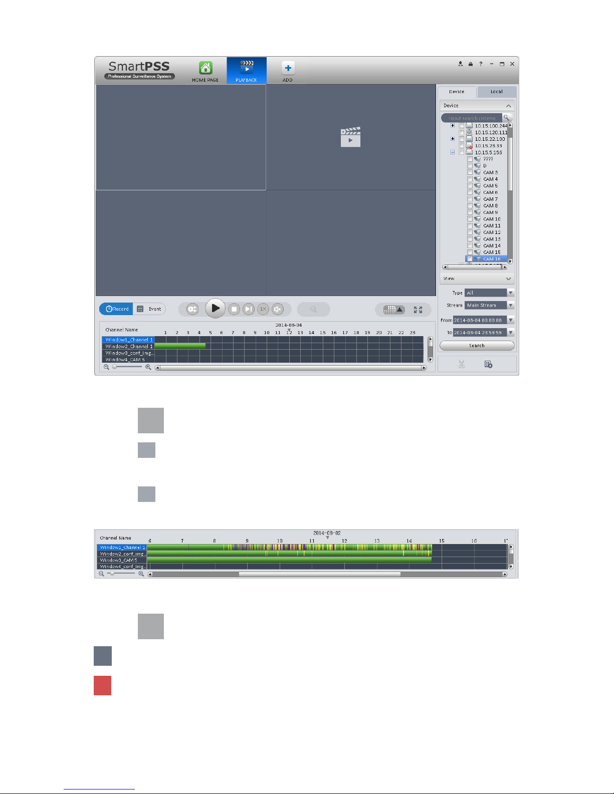
4.2.1 Playback Device Record
Please follow the steps listed below to search the record you want and then playback.
1) In Figure 4-7, click Device button on the upper right intergface.
2) Check a channel (or some channels) on the device list on the top right pane.
3) Select record type, stream type and record start time and end time.
4) Click Search. See Figure 4-8.
Page 92
88
Figure 4-8
5) Click to play record.
6) Click to intelligently search motion detection. System shows motion detection window.
7) Left click to select motion detection area.
8) Click to search motion detection. The purple time bar represents found motion detection
in Figure 4-9.
Figure 4-9
9) Click to play motion detection in video window.
: Re-select motion detection area.
: Exit.
Page 93

89
4.2.2 Playback Local Record
Please follow the steps listed below to search the record you want and then playback.
1) In Figure 4-7, click Local button on the right pane.
2) Check a channel (or some channels) on the device list on the top right pane.
3) Select record start time and end time.
4) Click on the left bottom to search. You can see the
corresponding dialogue box if there is no record.
5) Now you click to playback window.
4.2.3 Export
There are three ways for you to select export records.
In Device record interface, select periods on the time line and then click to export
records.
In Record event interface, select record type and then click to export records.
In Local record interface, check the records first and then click to expoer records.
You can see the export interface is shown as in Figure 4-10. Select the corresponding export
path and then click OK button to export.
Figure 4-10
You can click to view exporting and exported conditoions.
4.3 Alarm Manager
If you have set an alarm scheme, you can see the corresponding alarm in the Alarm manager
interface. You can refer to chapter 3.7.1 to set an alarm scheme first.
Click icon in the basic pane, you can go to Alarm manager interface. See Figure 4-11.
Page 94

90
Figure 4-11
If you have set alarm activation video function in your alarm scheme setup (chapter 3.7), you can
see system instantly shows video window. See Figure 4-12.
If you check the box at the bottom of the interface to pause refresh, the new alarm info will not be
shown in alarm list instantly. Click Alarm Manager at the right bottom of the interface, system
goes to the alarm manager interface for you to view the corresponding alarm record.
Figure 4-12
4.4 Log
Page 95

91
Log interface is shown as in Figure 4-13.
Select start time/end time, and select type from the dropdown list. Click Search button, you can
see the log information.
Figure 4-13
Page 96

92
5 Extension
5.1 Video Wall
After you set video wall setup (chapter 3.8 ), you can output video to the video wall. You can
follow the steps listed below to set.
1) Click icon on the main interface, you can go to the following interface. See Figure
5-1.
Figure 5-1
SN
Item
Function
1
Video
window
Connect to NVD:Video window is fixed, cannot be dragged.
Connect to M30 :Video window can be moved, max is 16.
2
Video
channel
-
Page 97

93
SN
Item
Function
3
Video open
window
Connect to NVD: Select one video window, click
to open 1*1, 2*2, 3*3, 4*4 layouts of windows.
Connect to M30:Click to open 1*1, 2*2, 3*3,
4*4 or M*N layouts of windows.
4
Clear
screen,
open/close
window
:Clear all video channels or layouts on screen.
:Screen on/off setup,to open/close TV wall displsy.
:Clear screen and open window.
2) Select corresponding video wall from the screen information dropdown list. You can check to
select real-time mode if necessary. Once you enable real-time mode, system automatically
output the video to the video wall after you complete the setup. Otherwise, it does not output
the video to the video wall.
3) Drag the channel on the right pane to the corresponding screen and then binding.
You can view details of binding video in Internet Explorer.
1. In IE, enterM30 or NVD device’s IP address.
2. Download web service pack.
3. After download is complete, system pops up login interface. See
Figure 5-2
4. Enter username and password, click Login to view details of bound video source.
Default username and password is admin/admin.
4) Click save as task button, you can see system pops up a dialogue box for you to input task
name.
5) Please input task name and click Save button.
6) Click Output video.
Please note:
Page 98

Page 99

95
Figure 5-4
After you added an e-map, the interface is shown as below. See Figure 5-5.
Figure 5-5
5.2.2 Edit E-map
Click , you can go to the following interface. See Figure 5-6.Click Tools, you can edit emap, delete e-map, delete device, add area, modify area, delete area and etc.
Drag a channel on the right pane to the e-map; you can add it to the e-map.
Page 100

96
Figure 5-6
Click button, you can see a function bar shown as below. See Figure 5-7.
Figure 5-7
Please refer to the following sheet for detailed information.
Item
Function
Modify e-map
It is for you to change e-map name, picture, description
Delete e-map
Delete current e-map.
Delete device
Delete a device from the e-map.
Add area
Add hot zone on the e-map.
 Loading...