

Dahua SD6AE230F-HNI Installation Manual

IR Intelligent Speed Dome Installation Manual
Version 1.0.2

i
Table of Contents
1 IR INTELLIGENT SPEED DOME INSTALLATION ............................................. 1
1.1 Installation Preparation ......................................................................................................................... 1
1.2 Check Accessories ................................................................................................................................ 2
1.3 Open the Device .................................................................................................................................... 2
1.4 Dial Switch Setup................................................................................................................................... 2
1.4.1 Dial Switch Address and Function .................................................................................................. 2
1.4.2 Dial Switch Setup .............................................................................................................................. 4
1.4.3 Address Setup ................................................................................................................................... 4
1.4.4 Baud Rate, Parity Setup, HD/SD Video Mode Setup .................................................................. 5
1.4.5 Terminal Matched Resistance Setup ............................................................................................. 6
1.5 Reset and SD Card Installation (network speed dome) .................................................................. 6
1.6 Speed Dome Installation ...................................................................................................................... 7
Note: ...................................................................................................................................................................... 7
1.6.1 Quick Installation Connector ........................................................................................................... 7
1.6.2 Cable Connection ............................................................................................................................. 8
1.6.3 Install the speed dome ..................................................................................................................... 9
2 BRACKET DIMENSIONS ................................................................................. 11
2.1 Wall Mount Bracket ............................................................................................................................. 11
2.2 Hanging Mount Bracket (Multiple Lengths) ..................................................................................... 11
2.3 Corner Mount Bracket ......................................................................................................................... 12
2.4 Pole Mount Bracket ............................................................................................................................. 13

ii
3 WALL MOUNT BRACKET INSTALLATION ...................................................... 15
3.1 Component Installation ....................................................................................................................... 15
3.2 Installation ............................................................................................................................................. 15
3.2.1 Installation Requirements .............................................................................................................. 15
3.2.2 Installation Steps ............................................................................................................................. 15
4 HANG MOUNT BRACKET INSTALLATION ..................................................... 18
4.1 Component Installation ....................................................................................................................... 18
4.2 Installation ............................................................................................................................................. 18
4.2.1 Installation Requirements .............................................................................................................. 18
4.2.2 Installation Steps ............................................................................................................................. 18
5 CORNER MOUNT BRACKET INSTALLATION ................................................ 21
5.1 Component Installation ....................................................................................................................... 21
5.2 Installation ............................................................................................................................................. 21
5.2.1 Installation Requirements .............................................................................................................. 21
5.2.2 Installation Steps ............................................................................................................................. 21
6 POLE MOUNT BRACKET INSTALLATION ...................................................... 24
6.1 Installation ............................................................................................................................................. 24
6.1.1 Installation Requirements .............................................................................................................. 24
6.1.2 Installation Steps ............................................................................................................................. 24
7 APPENDIX Ⅰ LIGHTNING PROOF AND SURGE PROTECTION ..................... 27
8 APPENDIX Ⅱ ABOUT RS485 BUS ................................................................... 28

iii
8.1 RS485 Bus Main Feature ................................................................................................................... 28
8.2 RS485 Bus Transmission Distance .................................................................................................. 28
8.3 The Problem in Practical Use ............................................................................................................ 28
8.4 RS485 Bus FAQ .................................................................................................................................. 29
9 APPENDIX Ⅲ THE RELATIONSHIP BETWEEN THE 24V AC CABLE
DIAMETER AND THE TRANSMISSION DISTANCE ............................................... 30
10 APPENDIX Ⅳ THE RELATIONSHIP BETWEEN THE 12V DC CABLE
DIAMETER AND THE TRANSMISSION DISTANCE ............................................... 32
11 APPENDIX IV WIRE GAUGE REFERENCE SHEET ....................................... 34

iv
Welcome
Thank you for purchasing our speed dome!
Please read the following safeguards and warnings carefully before you install or use the
product!

v
Important Safeguards and Warnings
Safety Measures
1. Qualified Engineer Needed
The installation engineer or maintenance engineer shall have corresponding CCTV system
installation certificate or maintenance qualification certificate.
The installation engineer or maintenance engineer shall have qualification certificate for work
at height.
The installation engineer or maintenance engineer shall have the basic knowledge and
operation technique for low-voltage cable layout and low-voltage electronic cable connection.
Please read the installation manual carefully and keep it well for future reference,
We are not liable for any problems caused by unauthorized modifications or attempted repair.
2. Lifting Appliance Requirement
Please select the proper speed dome installation mode and use the lifting appliances at the
safety environment.
The lifting appliances shall have the enough capacity to reach the installation height.
The lifting appliances shall have safe performance.
The precaution measures include two types: Warning and Note.
Warning: It is to alert you there is an optional risk of death or series injury!
Note: It is to alert you there is an optional risk of damage or property loss!
Warning
1. All installation and operation here should conform to your local electrical safety codes. We
assume no liability or responsibility for all the fires or electrical shock caused by improper
handling or installation.
2. Be sure to use all the accessories (such as power adapter) recommended by manufacturer.
3. Laser light is dangerous; please do not look at it straight.
4. Do not connect several speed domes to one power adapter. It may result in overheat or fire
if it exceeds the rated load.
5. Before you connect the cable, install or uninstall, or begin the daily maintenance work,
please turn off the power and unplug the power cable.
6. Please make sure the produce is secure firmly on the wall or the ceiling.

vi
7. Please turn off the power and unplug the power cable, If there is any smoke, disgusting
smell, or noise. Please contact your local retailer or customer service centre for help.
8. All the examination and repair work should be done by the qualified service engineers. We
are not liable for any problems caused by unauthorized modifications or attempted repair.
Note
1. Safety Transportation
Heavy stress, violent vibration or water splash are not allowed during transportation, storage
and installation.
This series product must use split type package during the transportation.
We are not liable for any damage or problem resulting from the integrated package during
the transportation.
2. When device is malfunction
Shut down the device and disconnect the power cable immediately if there is smoke, abnormal
smell or abnormal function. Please contact your local retailer ASAP.
3. Do not try to dismantle or modify the device
There is risk of personal injury or device damage resulting from opening the shell.
Please contact your local retailer if there is internal setup or maintenance requirement.
We are not liable for any problems caused by unauthorized modifications or attempted repair.
4. Do not allow other object falling into the device
Please make sure there is no metal or inflammable, explosive substance in the speed dome.
The above mentioned objects in the device may result in fire, short-circuit or damage.
Please shut down the device and disconnect the power cable if there is water or liquid falling
into the camera. Please contact your local retailer ASAP.
Please pay attention to the camera. Avoid the sea water or rain to erode the camera.
5. Handle carefully
Do not allow this series product fall down to the ground.
Avoid heavy vibration.
6. Installation Environment Requirement
This series speed dome should be installed in a cool, dry place away from direct sunlight,
inflammable, explosive substances and etc.
This series product shall be away from the strong electromagnetism radiant, please keep it
away from wireless power, TV transmitter, transformer and etc.
7. Daily Maintenance

vii
Please use the soft cloth to clean dust on the shell, or you can use soft cloth with cleaning
liquid to clean the shell and then use soft cloth to make it dry.
Do not use gasoline, dope thinner or other chemical material to clean the shell. It may result
in shell transfiguration or paint flake.
Do not allow the plastic or rubber material to touch the shell for a long time. It may result in
paint flake.
It is highly recommended to use the product with a lightning-proof device, which can realize
better lightning-proof effect.
1
1 IR INTELLIGENT SPEED DOME INSTALLATION
1.1 Installation Preparation
Basic Requirement
All installation and operation here should conform to your local electrical safety codes.
Before installation, please open the package and check all the components are included.
Please make sure the speed dome installation environment and installation mode can meet
your requirement. If there is special requirement, please contact your local retailer for more
information.
We assume no liability or responsibility for all the fires or electrical shock caused by
improper handling or installation.
Check installation space and installation location intension
Please make sure the installation environment has enough space to install the speed dome and
its corresponding bracket.
Please make sure the ceiling, wall and the bracket can support the speed dome and its
corresponding installation component. It shall sustain the 8X weight of the speed dome. Please
notice that the installation height should be more than 6m if it is a laser speed dome.
About cable
Please select the cable according to your transmission distance.
The minimum video coaxial-cable requirement is:
75 ohm.
Full cable with copper conductor
95% knitted copper shield
International Model
Max Distance
(Ft\M)
RG59/U
750ft (229m)
RG6/U
1,000ft (305m)
RG11/U
1,500ft (457m)
Please refer to appendix 2 for more information about RS485 communication cable.
Select proper power supply cable according to transmission distance
Refer to appendix 3 for 24VAC power supply device.
Refer to appendix 4 for 12VDC power supply device.
Please keep all package material well for future use
Please keep speed dome package material well in case you need to send it back to your local
retailer or manufacturer for maintenance work.
Non-original package material may result in device damage during the transportation.

2
1.2 Check Accessories
Before the installation, please check the accessories one by one according to the packing list.
Please make sure all the components listed are includes.
1.3 Open the Device
Please open the box and then take out the speed dome. See Figure 1-1.
Figure 1-1
Note:
There are two types of IR intelligent speed dome which are shown in Figure 1-1, please refer to
the actual object for details.
There is laser light and IR light on the laser speed dome, the laser light is used for light
compensation while the IR light can be used to indicate whether the laser light is on or off, the
laser light is enabled when the IR light is on.
1.4 Dial Switch Setup
1.4.1 Dial Switch Address and Function
The corresponding functions of dial switch for both analog speed dome and HDCVI speed dome
are different, which will be introduced respectively.
1.4.1.1 Analog Speed Dome
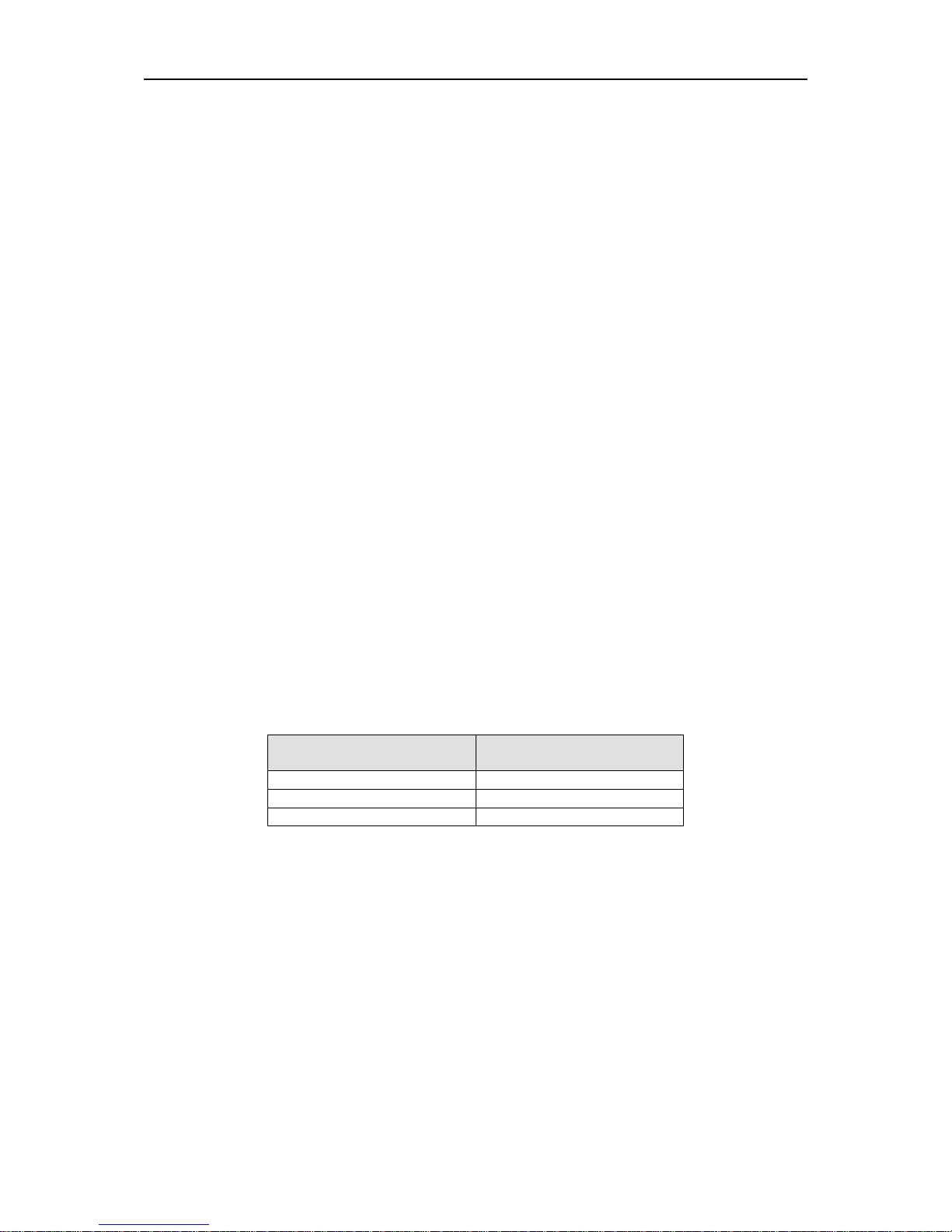
3
Open the cover of the speed dome; you can see there are two dial switch buttons on the PTZ
mainboard. You can use them to set speed dome address, baud rate and parity. Please refer to
Figure 1-2 for the dial switch address.
Figure 1-2
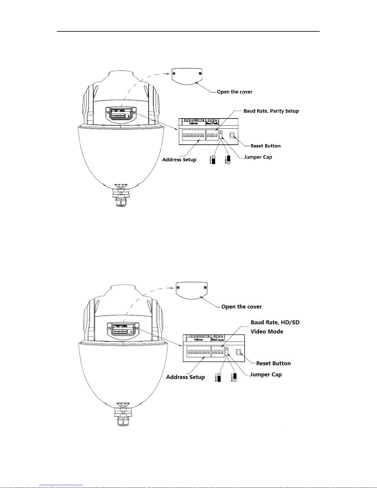
1.4.1.2 HDCVI Speed Dome
Open the cover of the speed dome; you can see there are two dial switch buttons on the PTZ
mainboard. You can use them to set speed dome address, baud rate and HD/SD video mode.
Please refer to Figure 1-3 for the dial switch address.
Figure 1-3
4
Note:
When HDCVI intelligent speed dome only uses coaxial control, dial-up and other related RS485
setup don’t have to be conducted.
1.4.2 Dial Switch Setup
Users must set the address, Baud rate or HD/SD video mode which is used by the speed dome
before controlling it. Only after all these settings, can the speed dome respond to its control
commands.
Note:
As for the wall-mounted speed dome, you need to install back the transparent cover component
after taking out the EPE and setting the dial switch address.
Users must reboot the speed dome after resetting some specifications, which makes the new
setup take effect.
There are two dial switch buttons on the speed dome PTZ which are used to confirm the speed
dome address, baud rate, parity or HD/SD vide mode. It is 1 when you set the button as ON. For
address setup dial switch, 1 is the lowest bit, 8 is the highest bit; for the Baud rate and parity
setup dial switch, 1 is the lowest bit, 4 is the highest bit. (Intelligent speed dome self-adaptive
PELCO-D, PELCO-P, industrial standard protocol, control protocol don’t need dial switch setup).
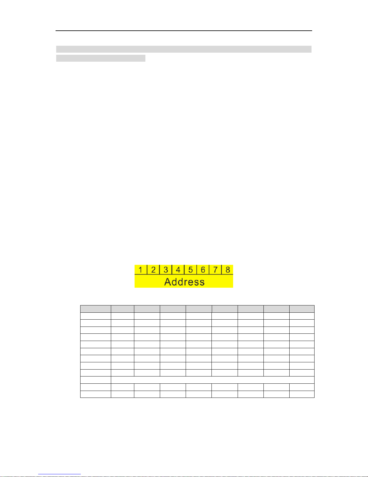
1.4.3 Address Setup
The speed dome uses dial switch to set address, the encode mode adopts binary system. 1 to 8
is valid bit. The highest address bit is 255; see Figure 1-4 for address and you can refer to the
sheet 1-1 for more information.
Figure 1-4
Address
1 2 3 4 5 6 7 8 0
OFF
OFF
OFF
OFF
OFF
OFF
OFF
OFF
1
ON
OFF
OFF
OFF
OFF
OFF
OFF
OFF
2
OFF
ON
OFF
OFF
OFF
OFF
OFF
OFF
3
ON
ON
OFF
OFF
OFF
OFF
OFF
OFF
4
OFF
OFF
ON
OFF
OFF
OFF
OFF
OFF
5
ON
OFF
ON
OFF
OFF
OFF
OFF
OFF
6
OFF
ON
ON
OFF
OFF
OFF
OFF
OFF
7
ON
ON
ON
OFF
OFF
OFF
OFF
OFF
8
OFF
OFF
OFF
ON
OFF
OFF
OFF
OFF
……
…………………………………………………………………
254
OFF
ON
ON
ON
ON
ON
ON
ON
255
ON
ON
ON
ON
ON
ON
ON
ON
Sheet 1-1
5
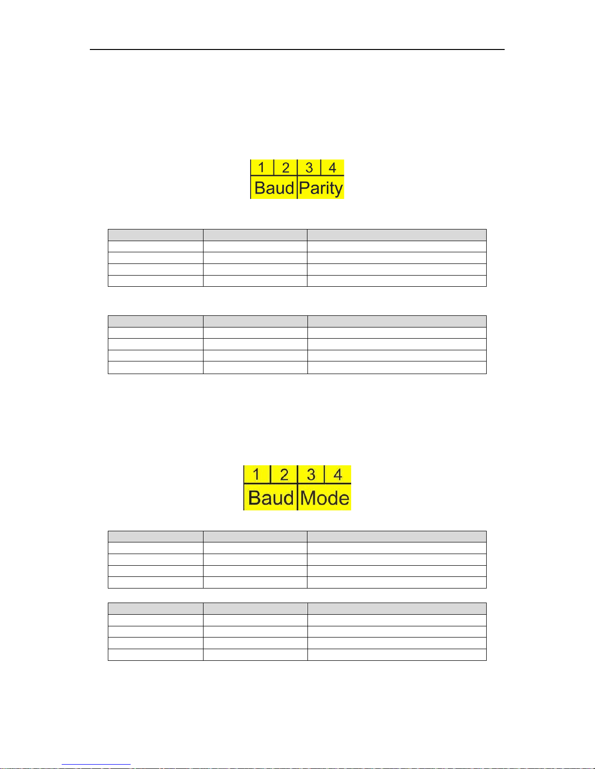
1.4.4 Baud Rate, Parity Setup, HD/SD Video Mode Setup
The functions which need to be set are different for analog speed dome and HDCVI speed dome,
which will be introduced respectively.
1.4.4.1 Analog Speed Dome
It is used to set speed dome Baud rate and parity. 1 and 2 bits are used to set Baud rate while 3
and 4 bits are used to set parity, see Figure 1-5.
Figure 1-5
Please refer to the baud rate setup sheet1-2 for detailed information.
1 2 Baud rate
OFF
OFF
9600bps
ON
OFF
4800bps
OFF
ON
2400bps
ON
ON
1200bps
Sheet 1-2
Please refer to the parity setup sheet 1-3 for detailed information.
3 4 Parity
OFF
OFF
NONE
ON
OFF
EVEN
OFF
ON
ODD
ON
ON
NONE
Sheet 1-3
1.4.4.2 HDCVI Speed Dome
It is to set the speed dome baud rate and HD/SD video mode. From 1 to 4 dial switch, 1 and 2 bit
are used to set Baud rate, 3 and 4 bit are used to set HD/SD video mode. See Figure 1-6 for
Baud rate and mode; refer to sheet 1-4 and 1-5 for Baud rate and mode setup.
Figure 1-6
1 2 Baud rate
OFF
OFF
9600bps
ON
OFF
4800bps
OFF
ON
2400bps
ON
ON
1200bps
Sheet 1-4
3 4 HD/SD video mode
OFF
OFF
HD
ON
OFF
SD
OFF
ON
Self-adaptive
ON
ON
HD
Sheet 1-5
 Loading...