

Dahua PSD81602-A360 Operation Manual

Dahua Panoramic + PTZ Network Camera Web3.0
Operation Manual
Version 1.0.0
ZHEJIANG DAHUA VISION TECHNOLOGY CO., LTD.

Table of Contents
1 Product Introduction ...................................................................................................... 1
1.1 Product Overview .............................................................................................. 1
1.2 Function Features ............................................................................................. 2
2 Basic Config .................................................................................................................. 5
2.1 Modify IP Address ............................................................................................. 5
2.1.1 Modify Individually ................................................................................ 5
2.1.2 Modify in Batches ................................................................................. 7
2.2 Log in WEB Interface ........................................................................................ 8
2.3 Modify User Password .................................................................................... 10
3 General Operation ....................................................................................................... 13
3.1 Live ................................................................................................................. 13
3.1.1 Live Interface Introduction .................................................................. 13
3.1.2 Video Window Function ...................................................................... 14
3.1.3 Video Window Adjustment .................................................................. 15
3.2 Playback ......................................................................................................... 19
3.2.1 Video Playback ................................................................................... 20
3.2.2 Picture Playback ................................................................................. 26
3.3 Configure Alarm Info ....................................................................................... 28
3.3.1 Understand Alarm Type ...................................................................... 28
3.3.2 Subscribe Alarm Information .............................................................. 29
4 Config .......................................................................................................................... 31
4.1 Camera Setup ................................................................................................. 31
4.1.1 Set Camera Condition ........................................................................ 31
4.1.2 Set Video Parameter .......................................................................... 44
4.1.3 Configure Audio Parameters .............................................................. 58
4.2 Network Setup ................................................................................................ 60
4.2.1 Set TCP/IP Parameter ........................................................................ 60
4.2.2 Set Connection Parameter ................................................................. 64
4.2.3 Set PPPoE Parameter ........................................................................ 66
4.2.4 Set DDNS Parameter ......................................................................... 67
4.2.5 Set IP Filter ......................................................................................... 69
4.2.6 Set SMTP Parameter ......................................................................... 71
4.2.7 Set UPnP Parameter .......................................................................... 73
4.2.8 Set SNMP Parameter ......................................................................... 74
4.2.9 Set Bonjour Parameter ....................................................................... 78
4.2.10 Set Multicast ....................................................................................... 79
4.2.11 Set 802.1x Parameter......................................................................... 81

4.2.12 Set QoS Parameter ............................................................................ 82
4.3 Set PTZ Function ................................ ................................ ............................ 83
4.3.1 Set Preset ........................................................................................... 83
Step 2 ......................................................................................................................... 84
4.3.2 Set Tour .............................................................................................. 84
4.3.3 Set Scan ................................ ................................ ............................. 85
4.3.4 Set Pattern ......................................................................................... 86
4.3.5 Enable Pan ......................................................................................... 87
4.3.6 Set PTZ Speed ................................................................................... 88
4.3.7 Set Idle Motion ................................................................................... 89
4.3.8 Set PowerUp ...................................................................................... 90
4.3.9 Set Time Task .................................................................................... 91
4.3.10 PTZ Restart ........................................................................................ 93
4.3.11 Default ................................................................................................ 94
4.4 Event ............................................................................................................... 95
4.4.1 Set Smart Track ................................................................................. 95
4.4.2 Set Video Detection ............................................................................ 98
4.4.3 Set Audio Detection .......................................................................... 107
4.4.4 Smart Plan ........................................................................................ 109
4.4.5 Set IVS ............................................................................................. 111
4.4.6 Set Face Detection ........................................................................... 142
4.4.7 Set People Counting......................................................................... 144
4.4.8 Heat Map .......................................................................................... 149
4.4.9 Set Alarm .......................................................................................... 151
4.4.10 Abnormity ......................................................................................... 154
4.5 Storage ......................................................................................................... 158
4.5.1 Set Schedule .................................................................................... 158
4.5.2 Destination ....................................................................................... 162
4.5.3 Record Control ................................................................................. 166
4.6 System .......................................................................................................... 167
4.6.1 General ............................................................................................. 167
4.6.2 Account ............................................................................................ 170
4.6.3 Add Onvif User ................................................................................. 175
5 System Maintenance ................................................................................................. 178
5.1 Maintenance Requirements .......................................................................... 178
5.2 Auto Maintenance ......................................................................................... 178
5.2.1 Auto Reboot ..................................................................................... 178
5.2.2 Delete Old Files ................................................................................ 179
5.3 Backup and Recovery ................................................................................... 179

5.3.1 Backup Device Config Info ............................................................... 179
5.3.2 Recover Device Config Info .............................................................. 180
5.3.3 Default .............................................................................................. 181
5.4 Upgrade ........................................................................................................ 181
5.5 Version .......................................................................................................... 182
5.6 Log ................................................................................................ ................ 182
5.7 Online User ................................................................................................... 184

Important
The following functions are for reference only. Some series products may not
support all the functions listed below.
1 Product Introduction
1.1 Product Overview
The product series is able to provide video preview, record, smart track and intelligent behavior
analytics and so on based on the requirements of detail tracking, panoramic monitoring and large scene
monitoring of various industries. The product is widely applied in government enterprise, public facility
management and other industries, besides, it can provide practical serialized solutions separately or
combined with storage device for several application fields such as safe city, industrial park security and
public place safety etc. The product is equipped with following features.
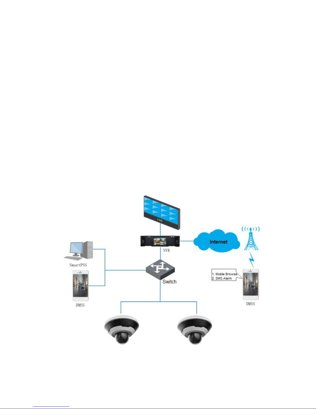
Panoramic coverage and detail tracking
Adopts integrated structure design, it can cover both overall and partial monitoring, the panoramic
camera is able to realize omnibearing coverage for the scene, the speed dome can implement quick
positioning and tracking upon details.
Multi-scenario intelligent application
It can realize intelligent detection, realtime alarm and evidence acquisition for abnormal behaviors via
intrusion and alarm linkage function in several application scenarios.
The main application scenario is shown in Figure 1-1.
Figure 1-1

1.2 Function Features
Realtime Monitoring
Function
Note
Live
Supports preview panoramic camera image and tracking speed dome
image at the same time. It can monitor panorama via panoramic
camera, meanwhile it can check details via manual tracking or
intelligent activated positioning by tracking speed dome.
Supports preview mode switch.
PTZ control
It can operate the tracking speed dome to position and recognize details
via PTZ.
Speed dome PTZ functions include camera rotation, scan, preset, tour,
pattern, pan and position etc.
Talk
It can contact front-end monitoring sites in time and deal with abnormities
quickly after talk is enabled.
Local snapshot
It can monitor the image abnormities via snapshot or triple snapshot during
preview, which is convenient to check and deal with abnormities
subsequently.
Local record
It can record abnormities of monitoring image during preview, which is
convenient to check and deal with abnormities subsequently.
others
Switch video stream or media protocol.
Manually position tracking speed dome to the target location in the
image of panoramic camera.
Zoom in partial area of the tracking speed dome image or roll mouse
to zoom tracking speed dome image.
Check if there is alarm output.
Zoom in partial details of the video image.
Manually track target via tracking speed dome.
It can automatically track target when the target triggers intelligent
rules and generate alarm after setting intelligent rules.
Adjust display effect of the monitoring image.
Enable or disable intelligent rules display.
Supports full screen preview.
Supports to adjust fluency of video image.
Supports to display the video image of panoramic camera and tracking
speed dome according to different layout.
Record
Function
Note
Scheduled
record
The system is able to record automatically according to the schedule which
has been set after scheduled record is set.
Video playback
and download
Playback video files, check valuable video clip. Download valuable video
clip, which can be used as evidence for judgement.
Picture playback
Playback snapshot and check valuable captured pictures.
Alarm linkage
record
It is able to activate corresponding channel to record when alarm happens.
Alarm

Set alarm prompt mode or voice according to alarm type.
Check alarm information.
User Management
Function
Note
User group
management
Support to add, modify and delete new user group.
Support to manage user authority according to user group.
User
Management
Support to add, modify and delete users.
Support to set user authority.
Modify password
Support to modify user password.
Event Management
Function
Note
Smart Track
Support smart track between bullet and speed dome.
Support switch between smart track and tracking speed dome linkage.
Video Detection
Support motion detection, video tamper and scene changing.
When alarm happens, it supports a series of linkage actions, such as
record, relay-out, send email, PTZ and snapshot etc.
Audio Detection
Support input abnormity and intensity change.
When alarm happens, it supports a series of linkage actions, such as
record, relay-out, send email, PTZ and snapshot etc.
IVS
Support general behavior analysis of panoramic camera and tracking
speed dome.
Panoramic camera supports intrusion and tripwire, tracking speed dome
supports cross fence, tripwire, intrusion, object abandoned, fast moving,
parking detection, crowd gathering, object missing and loitering detection.
When alarm happens, it supports a series of linkage actions, such as
linked tracking, linked record, relay-out, send email, PTZ and snapshot etc.
Support to add calibration area, filter disturbance and shadow, valid target
filtration.
Face Detection
Only tracking speed dome supports face detection.
When alarm happens, it supports linked record, relay-out, send email, PTZ
and snapshot etc.
People Counting
Only tracking speed dome supports people counting.
When alarm happens, it supports linked record, relay-out, send email, PTZ
and snapshot etc.
Heat Map
Only tracking speed dome supports heat map.
It supports to check report of heat map.
Alarm Setting
It triggers alarm when external alarm inputs device and generates alarm.
When alarm happens, it supports linked record, relay-out, send email, PTZ
and snapshot etc.

Function
Note
Abnormity
Supports SD card abnormity, network abnormity and illegal access
detection.
It supports linked relay-out and send email when SD card abnormity or
illegal access alarm happens.
It supports linked record and relay-out when network abnormity alarm
happens.

2 Basic Config
2.1 Modify IP Address
The default IP address of all the devices is 192.168.1.108, please modify device IP address according
to network planning for the first use or during network adjustment.
You can modify device IP address individually or in batch via ConfigTool, you can also log in WEB client
to modify the device IP address.
You can modify device IP address individually when there are less devices or the device login
password is not the same.
You can modify device IP address in batches when there are more devices or the device login
password is the same.
Precondition
ConfigTool installation package has been acquired, please consult technical service if not.
Network intercommunication between PC installed with ConfigTool and device.
2.1.1 Modify Individually
It is going to introduce how to modify device IP address individually via ConfigTool in this chapter.
Note
Please refer to "4.2.1 Set TCP/IP Parameter" for details about modifying IP address via WEB client
login
Step 1
Click and the system displays the interface of Modify IP.
Step 2
Click Search Setting and the system displays the dialog box of Setting, which is shown in Figure 2-1.
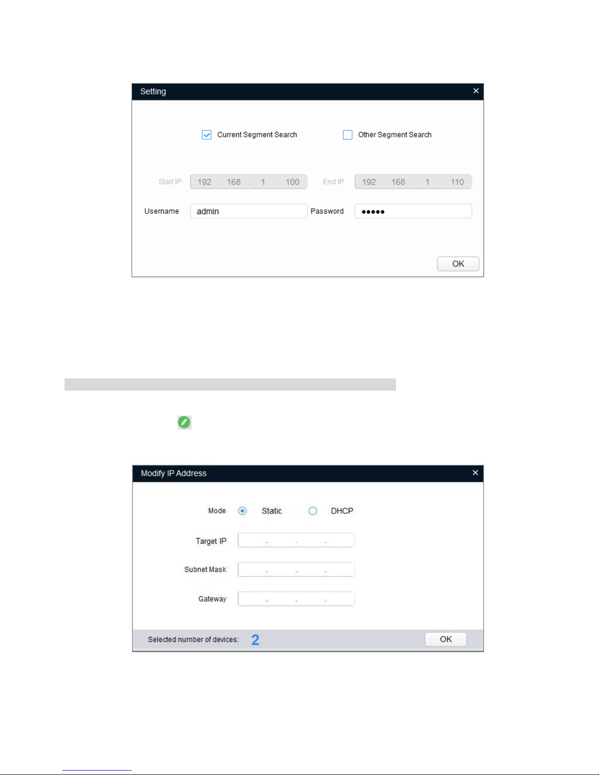
Figure 2-1
Step 3
Set the device network segment, login user name and password, and then click OK. The system will
display the searched devices after searching completes.
Note
The default username and password is admin and admin respectively.
Step 4
Click the corresponding of the device whose IP needs to be modified.
The system will pop out a dialog box of Modify IP, which is shown in Figure 2-2.
Figure 2-2
Step 5
Select the mode of setting IP address according to the actual situation.
DHCP: Set mode as DHCP when there is DHCP server in the network, then the device will
automatically acquire IP address from DHCP server.
Manual mode: Set mode as Static and fill in the Target IP, Subnet Mask and Gateway, and then
the device IP address is modified into the IP address which has been set.
Step 6
Click OK to complete modification.
2.1.2 Modify in Batches
Step 1
Click and the system displays the interface of Modify IP.
Step 2
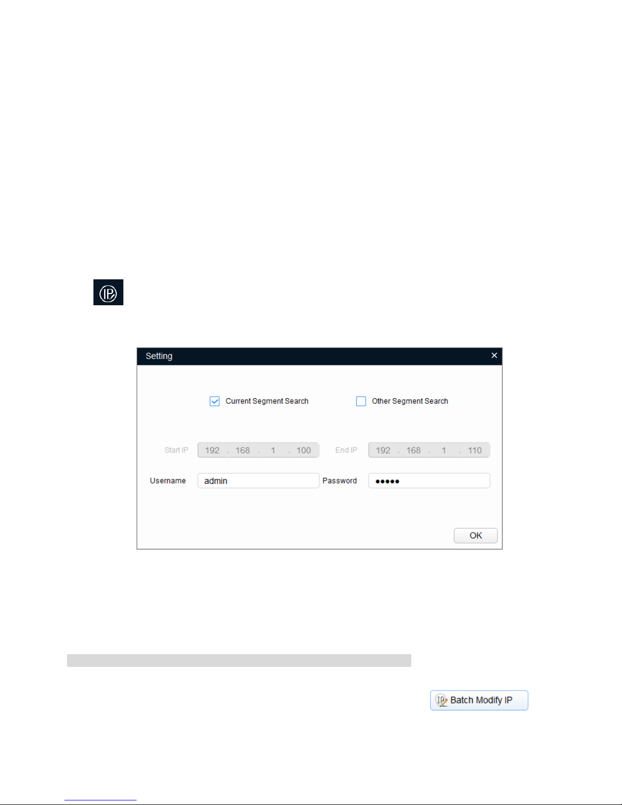
Click Search Setting and the system displays the dialog box of Setting, which is shown in Figure 2-3.
Figure 2-3
Step 3
Set the device network segment, login user name and password, and then click OK. The system will
display the searched devices after searching completes.
Note
The default username and password is admin and admin respectively.
Step 4
Select the devices whose IP addresses need to be modified, and then click .
The system will pop out a dialog box of Modify IP, which is shown in Figure 2-4.
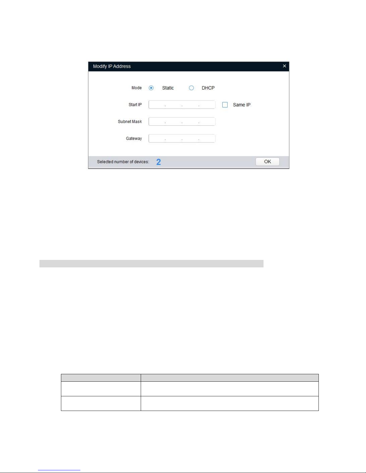
Figure 2-4
Step 5
Select the mode of setting IP address according to the actual situation.
DHCP: Set mode as DHCP when there is DHCP server in the network, then the device will
automatically acquire IP address from DHCP server.
Manual mode: Set mode as Static and fill in the Start IP, Subnet Mask and Gateway, and then the
device IP address will be modified from Start IP sequentially.
Note
Select Same IP and the selected devices will be set with the same IP address.
Step 6
Click OK to complete modification.
2.2 Log in WEB Interface
It can log in device WEB interface via browser and realize device operation, config and maintenance
after IP address has been modified.
Background Info
Please refer to Table 2-1 for the recommended config of PC which logs in device WEB interface.
PC Component
Recommended Config
Operating System
Windows 7 and higher
CPU
Intel core i3 and higher
Graphics Card
Intel HD Graphics and higher
Internal Storage
2GB and higher
Monitor
1024×768 and higher
Browser
Internet Explorer 8/9/10/11
Table 2-1
Operation Steps
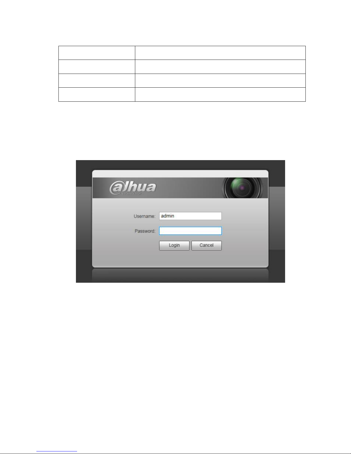
Step 1
Open browser, input camera IP address into the address bar and click Enter button. The system will
display Login interface after it is successfully connected, which is shown in Figure 2-5.
Figure 2-5
Step 2
Input Username and Password, click Login.
The system will display the Live interface after successful login, which is shown in Figure 2-6.
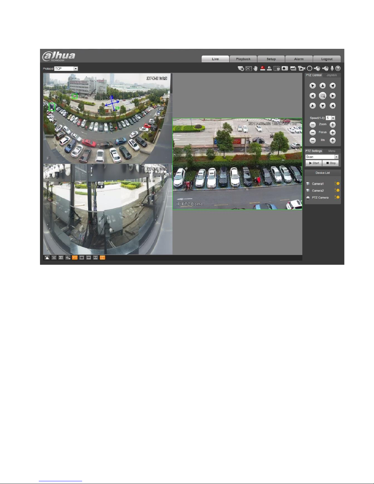
Figure 2-6
Note
Click the Logout button on the upper right corner to log out the system.
2.3 Modify User Password
Please make sure to modify the default password of the device and modify password regularly in order
to guarantee device security. Meanwhile it is recommended to modify the password with high
complexity.
Step 1
Select "Setup > System > Account > User" and the system will display the interface of User Name,
which is shown in Figure 2-7.
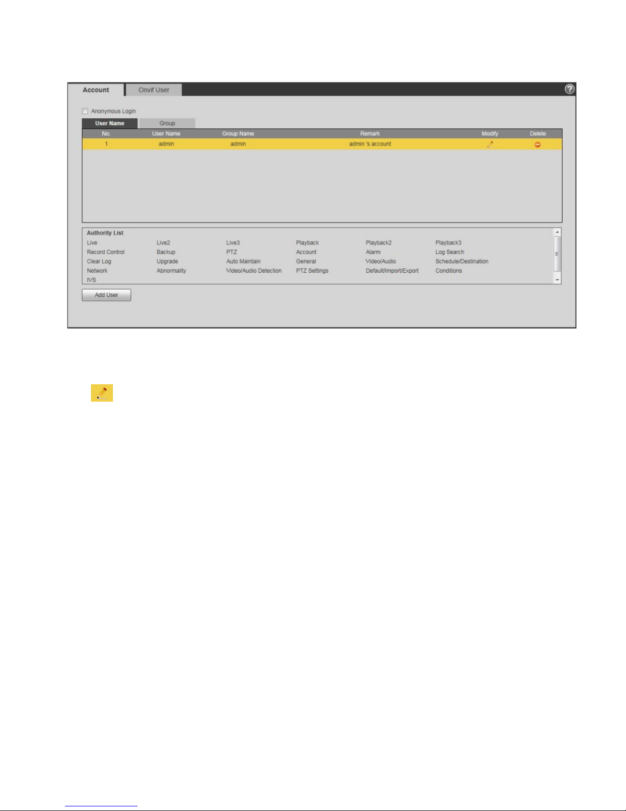
Figure 2-7
Step 2
Click . The system will pop out the dialogue box of Modify User.
Step 3
Select Modify Password. The system will display the interface which is shown in Figure 2-8.
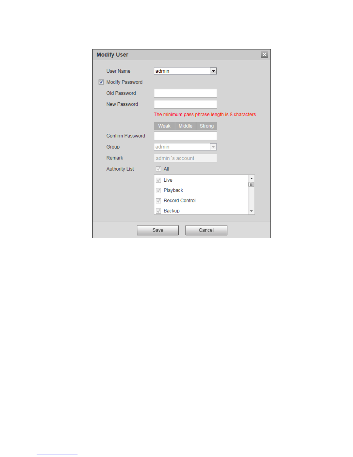
Figure 2-8
Step 4
Enter Old Password, New Password and Confirm Password.
Step 5
Click Save to complete password modification.

3 General Operation
3.1 Live
Users can implement a series of operations such as Live, Snapshot and Record etc. upon realtime
monitoring image on the Live interface.
Note
Different devices may have different functions, please refer to the actual interface for more details.
Double click the image and the image of this channel will be full screen displayed, double click or press
Esc button, the image will be recovered to original size.
3.1.1 Live Interface Introduction
Click Live and the system will display the Live interface, which is shown in Figure 3-1. The Live
interface of WEB client contains five functions, please refer to Figure 3-1 for more details.
Figure 3-1
SN
Name
Note
1
System menu
Click the function name on the system menu column to enter
corresponding config interface.
2
Code setting
Stream media protocol, types of network transmission protocol,
including TCP, UDP and multicast.
3
Video window
function
Please refer to "3.1.2 Video Window Function" for more details.
4
PTZ control
Please refer to "3.1.3.5 PTZ Control" for more details.
5
Video window
adjust
Please refer to "3.1.3 Video Window Adjust" for more details.
6
Switch stream
Display device list and switch main stream and substream.
Click on the right of corresponding camera, then you can switch
preview stream, please select according to actual situation. and
represents substream 1 and substream 2 respectively;
Means main stream.
For mainstream, it has big code stream with high image definition,
but it occupies big bandwidth, suitable for storage and monitoring.
For substream, code stream is comparatively smaller than
Main stream, the image is quite fluent and it occupies small
bandwidth, suitable for monitoring instead of main stream when
network bandwidth is not enough.
Table 3-1
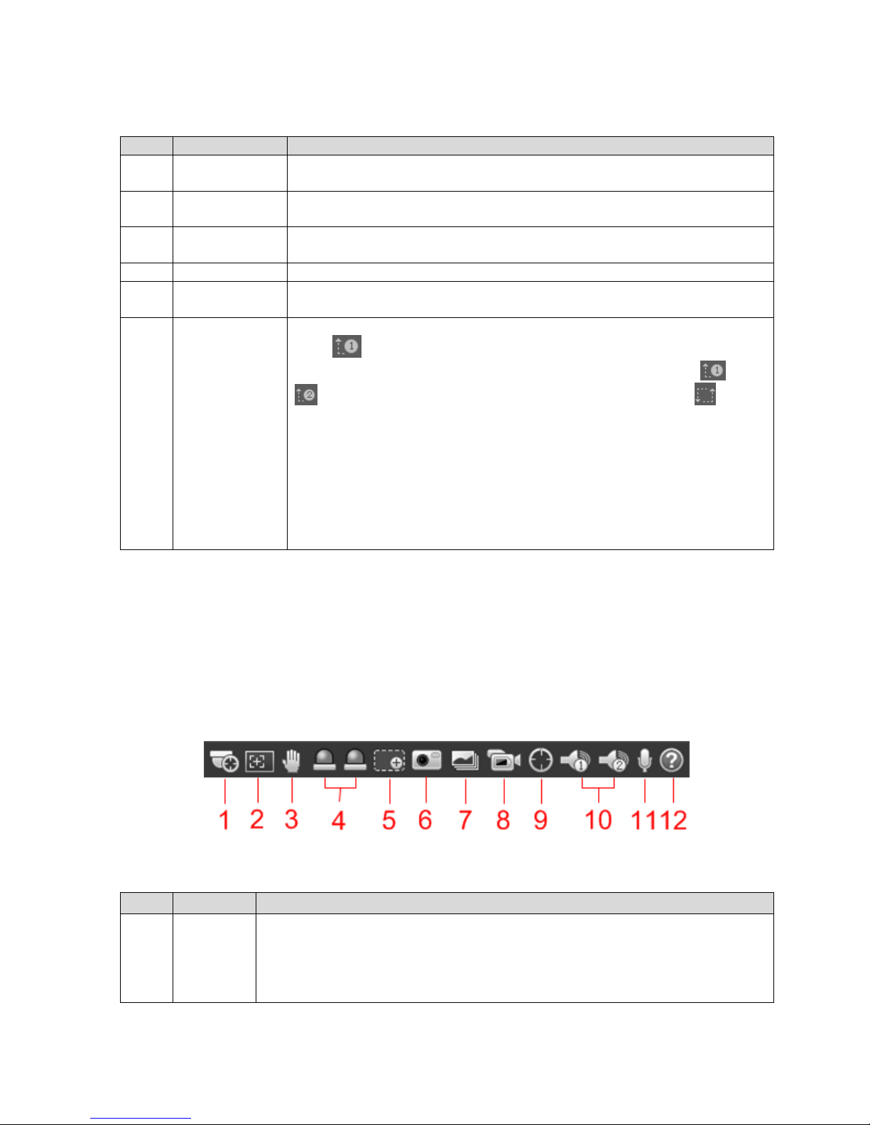
3.1.2 Video Window Function
The video window function option is shown in Figure 3-2. Please refer to Table 3-2 for more details
about each icon.
Note
Different devices may have different functions, please refer to the actual interface for more details.
Figure 3-2
SN
Name
Note
1
Manual
Position
Manually position the tracking speed dome to the selected location of
corresponding panoramic camera.
Select image of panoramic camera channel, click the icon and click or
select randomly on the image of panoramic camera channel, the tracking
speed dome will automatically position the selected location.
SN
Name
Note
2
Regional
Focus
It can realize auto focus in the selected area of the tracking speed dome.
Select channel image of the tracking speed dome, click the icon and click
or select randomly on the channel image of the tracking speed dome, and
then the speed dome can realize auto focus upon the selected region.
3
Gesture
It is to operate the mouse to control PTZ via the channel image of
tracking speed dome.
Select the channel image of tracking speed dome, click the icon and drag
image to control PTZ via pressing left button on the channel image of
tracking speed dome, it can zoom the image via rolling mouse wheel.
4
Relay-out
Display alarm output status, click the icon to compulsively enable or
disable alarm.
Red: It means outputting alarm.
Gray: it means ending alarm.
5
Digital
Zoom
After selecting the channel image, it supports the following two types of
zoom video image:
Click the icon, select regional area of the channel image to zoom in, click
right button to recover original status.
Click the icon and zoom video image size via rolling the mouse wheel.
6
Snapshot
Select channel image, click the icon and the system will auto take
snapshot upon the image of the selected channel.
7
Triple
Snapshot
Select channel image, click the icon and the system will auto take triple
snapshot upon the image of the selected channel.
8
Record
Click the icon and the system starts to record, the video will be stored in
the storage path which has been set. Please refer to 4.1.2.5 Set Storage
Path for more details about operation.
9
Manual
Track
Click the icon and drag left button to select tracking target on the preview
interface of the tracking speed dome, the system will auto track and
select the target.
10
Audio
Click it to enable or disable audio output of monitoring interface.
Note
Only the device with audio supports the function.
11
Talk
Click it to enable or disable bidirectional talk.
Please turn off stereophonic mixing on the computer when enabling
bidirectional talk.
Note
Only the device with audio supports the function.
12
Help
Click it to open help file.
Table 3-2
3.1.3 Video Window Adjustment
Note:
Different devices may have different functions, please refer to the actual interface for more details.
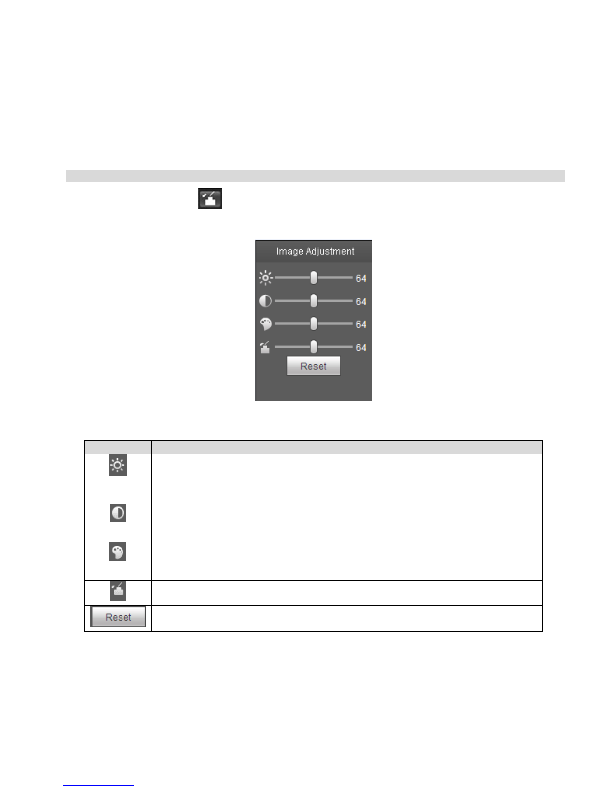
Figure 3-3
3.1.3.1 Local Image Adjustment
It is to adjust the brightness, contrast, hue and saturation of different channel video images on the local
WEB end.
Note
Please refer to 4.1.1 Camera for more details about the operation of actual image parameter adjustment.
Select channel image, click and it will display image adjustment interface on the right of preview
interface, which is shown in Figure 3-4.
Figure 3-4
Icon
Function
Note
Brightness
adjustment
Adjust the total brightness of the selected channel image, it
can adjust the value when the whole image is too bright or
too dark. Both the dark and bright area of the image will be
equivalently increased or decreased during adjustment.
Contrast
adjustment
It is to adjust the contrast of the selected channel image,
when the image total brightness is suitable, but the image
contrast is not enough, then it can adjust the value.
Hue adjustment
It is to adjust the color. There is a default value according to
the photosensitivity of the sensor. Generally the value
doesn't need to be adjusted greatly.
Saturation
adjustment
It is to adjust the color, the threshold will not affect the
overall brightness of the image.
Reset
Click the button to reset the brightness, contrast, hue and
saturation back to system default value.
Table 3-3
3.1.3.2 Full Screen Display
Click and the channel image will be displayed with full screen.
In full screen mode, double click the channel image or press Esc button to exit full screen display.
3.1.3.3 Adjust Fluency
It is to adjust the fluency of channel image.
Select the channel image, click to select fluency level, it supports realtime, general and fluency.
3.1.3.4 Intelligent Rules Display
It is to control video image display or disable rule info. It is enabled by factory default.
After configuring intelligent rules, click and select Enable, video image will display intelligent rules
and target detection box. Please select Disable if you need to cancel display.
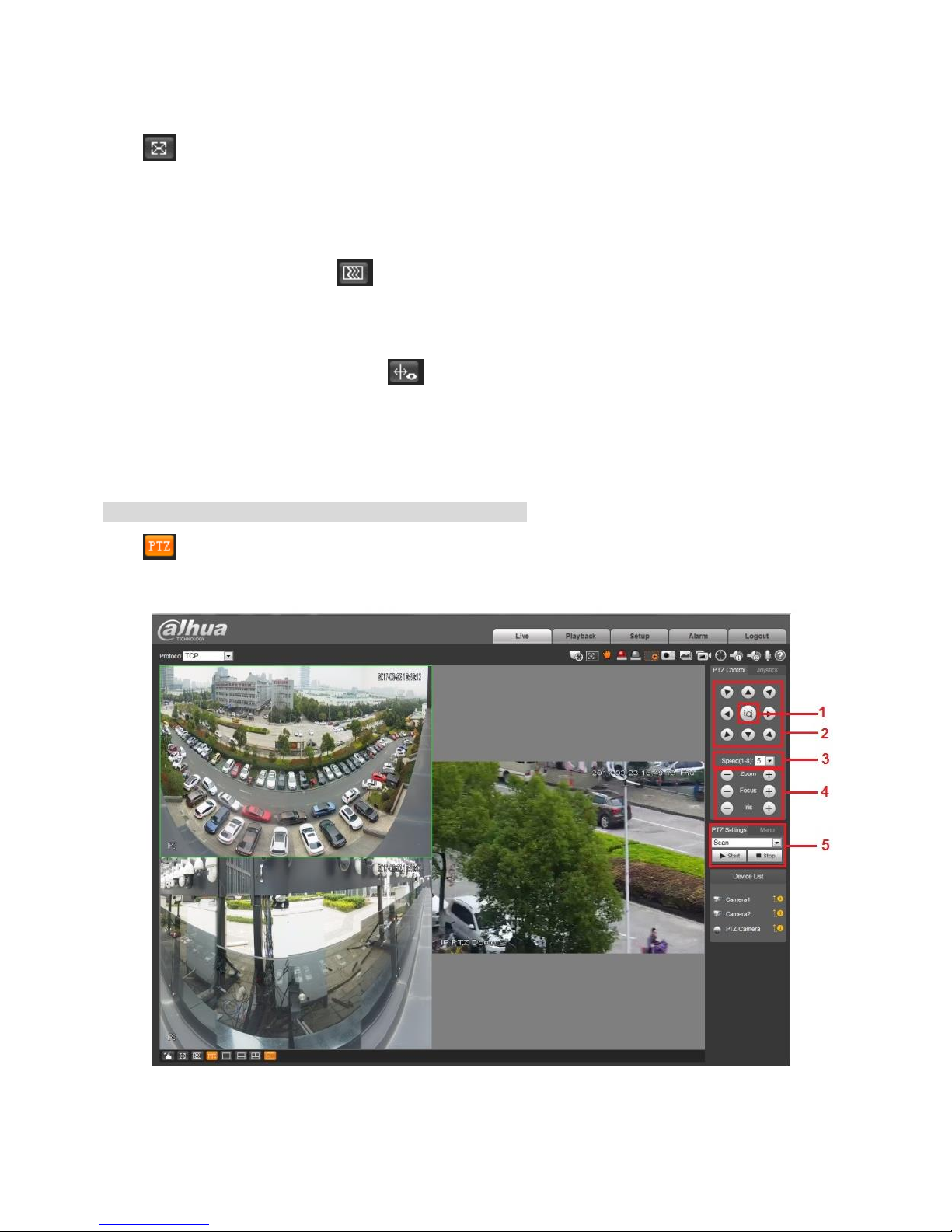
3.1.3.5 PTZ Control
It is to operate the PTZ of tracking speed dome.
Note
Only tracking speed dome supports PTZ control function.
Click and the system will display PTZ control panel, which is shown in Figure 3-5. Please refer to
Table 3-4 for the function of each button.
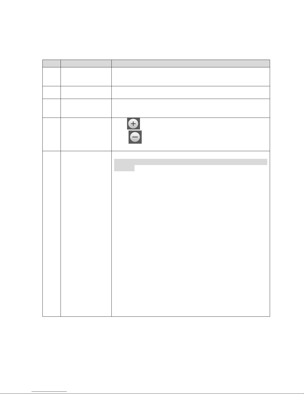
Figure 3-5
SN
Function
Note
1
Quick Position
It is the function of quick position. Use mouse to draw a box in
the monitoring image of tracking speed dome, and the PTZ will
quickly position to the scene.
2
Direction Button
It supports 8 directions, which are up, down, left, right, upper
left, upper right, lower left and lower right.
3
Speed
It is mainly used for speed operation, the bigger the step length
is, the faster the speed becomes. The step length is only valid to
PTZ direction control.
4
Zoom, Focus, Iris
Click and corresponding parameter value becomes bigger,
click and corresponding parameter value becomes
smaller.
5
PTZ Function
Note
It needs to complete 4.3 Set PTZ Function before using PTZ
function.
The supported PTZ functions include:
Scan
Click Start and the camera will automatically scan back and
forth in the area which has been set.
Preset
Select preset number, click Check and the camera will move to
the corresponding location of the preset.
Tour
Select tour number, click Start and the camera will automatically
move back and forth according to the preset sequence which
has been set.
Pattern
Select pattern number, click Start and the camera will
automatically move back and forth according to the moving
trajectory which has been set.
Assistant
Reserve extended function.
Go to
Input the needed horizontal and vertical angle, click Go to and it
can accurately position some spot.
Table 3-4
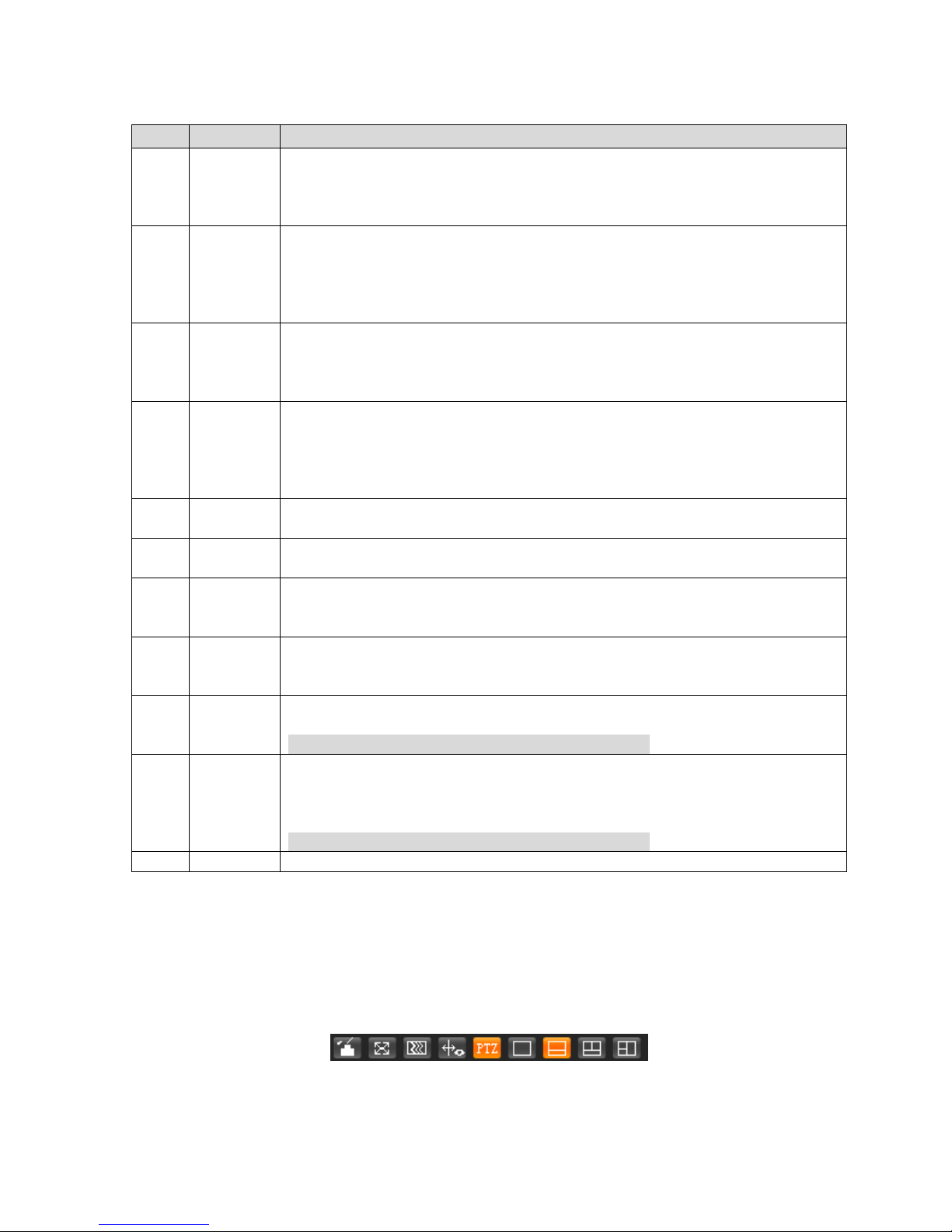
3.1.3.6 Window Layout
Select display layout of the channel image.

Single picture: Click and select the channel which needs to be displayed, support to select
panoramic camera 1, panoramic camera 2 or tracking speed dome.
Double picture: Click and the tracking speed dome is displayed by default, select panoramic
camera 1 or panoramic camera 2.
Triple picture: Panoramic camera 1, panoramic camera 2 and tracking speed dome are displayed
simultaneously, click and the panoramic cameras are displayed on the top and the tracking speed
dome is displayed on the bottom; click and panoramic cameras are displayed on the left and
tracking speed dome is displayed on the right.
3.2 Playback
WEB client playback supports video playback and picture playback.
Note
It needs to refer to 4.5 Storage for setting period, storage mode and record control of record and
snapshot before playback.
Different devices may have different functions, please refer to the actual interface for more details.
Click Playback and the system will display the interface of Playback, which is shown in Figure 3-6.
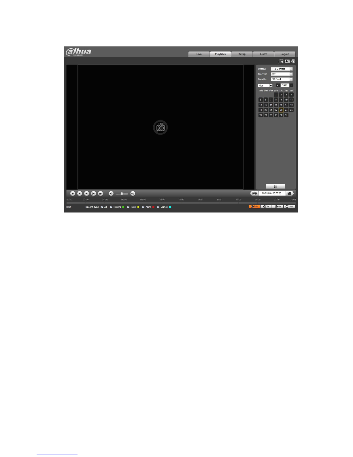
Figure 3-6
3.2.1 Video Playback
Video playback includes interface introduction, function column, playback video, video clip and aux
function.
3.2.1.1 Interface Introduction
It is to play video according to the requirement.
Select file type as "dav", and the system will display the interface of video playback, which is shown in
Figure 3-7, refer to Table 3-5 for more details.

Figure 3-7
SN
Function
Note
1
Play control bar
Play control button, refer to "3.2.1.2 Play Control Bar" for more
details.
2
Volume
adjustment bar
Control the volume during playback, which includes following two
states:
, it means mute state.
, it means voice broadcast state, volume can be adjusted.
3
Rule info bar
After enabling "Rule Info", the preview interface will display
intelligent rules and object detection box. It is enabled by default.
Note
If it is configured with intelligent rules during recording, then it is
valid by enabling "Rule Info" when play backing the recorded files.
4
Record type
Record type includes general, event, alarm and manual, you can
check the record type according to requirements.
SN
Function
Note
5
Progress bar
It is to display the record type and its period.
Click some spot in the color area, then it will begin to playback from
the time point.
Different record types mean different color, please refer to record
type selection bar for corresponding relations.
6
Progress bar
time format
It includes 、 、 和 four
types of format.. Take for example, it means the whole
progress bar is 24 hours.
7
Video cut bar
Cut some piece of video and save. Please refer to "3.2.1.4 Video
Clip" for more details.
8
Playback file
bar
Here it can select file type, data source and record date etc.
9
Aux function
bar
Aux function includes digital zoom and snapshot, please refer to
"3.2.1.5 Aux Function" for more details.
Table 3-5
3.2.1.2 Play Control Bar
Please refer to Table 3-6 for more description about play control.
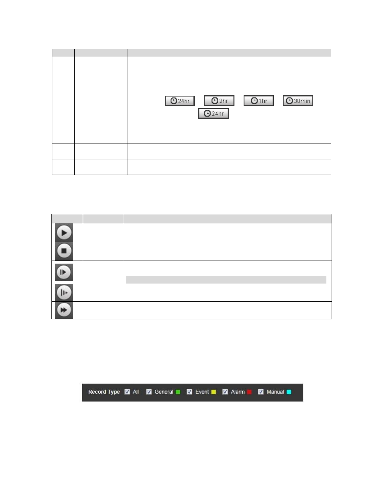
Icon
Function
Note
Play
When it displays the icon, it means pause or not playing video, click
the icon to switch to normal play state.
Stop
Click the icon to stop playing video
Play by
frame
Click the icon and skip to next frame to play.
Note
It needs to pause playback when using the function of play by frame.
Slow
forward
Click the icon and then it plays slowly.
Fast
forward
Click the icon and it plays fast.
Table 3-6
3.2.1.3 Playback Video
Step 1
Select record type in the "Record Type Selection Bar" according to requirement, which is shown in
Figure 3-8.
Figure 3-8
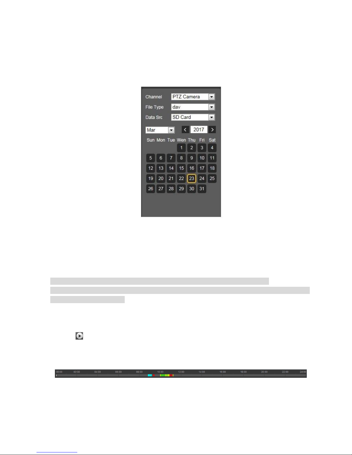
Step 2
Select the channel which needs to playback video, set "File Type" as dav", "Data Source" as "SD card",
which is shown in Figure 3-9.
File type includes dav and jpg, "dav" means video playback and "jpg" means picture playback.
Figure 3-9
Step 3
Select the month and year of the video which needs to be checked, click the date with blue background.
The system will display the record file progress bar with color.
Note
Display the date with blue background, it means there is record file on this date.
Different colors are corresponding to different record types on the progress bar, please refer to
Figure 3-8 for more details.
Step 4
Play video
Click the in the play control bar.
The system will play the record file of the selected date (According to time sequence)
Click some time point on the progress bar (area with color), which is shown in Figure 3-10.
The system will play the record file from this time point.
Figure 3-10
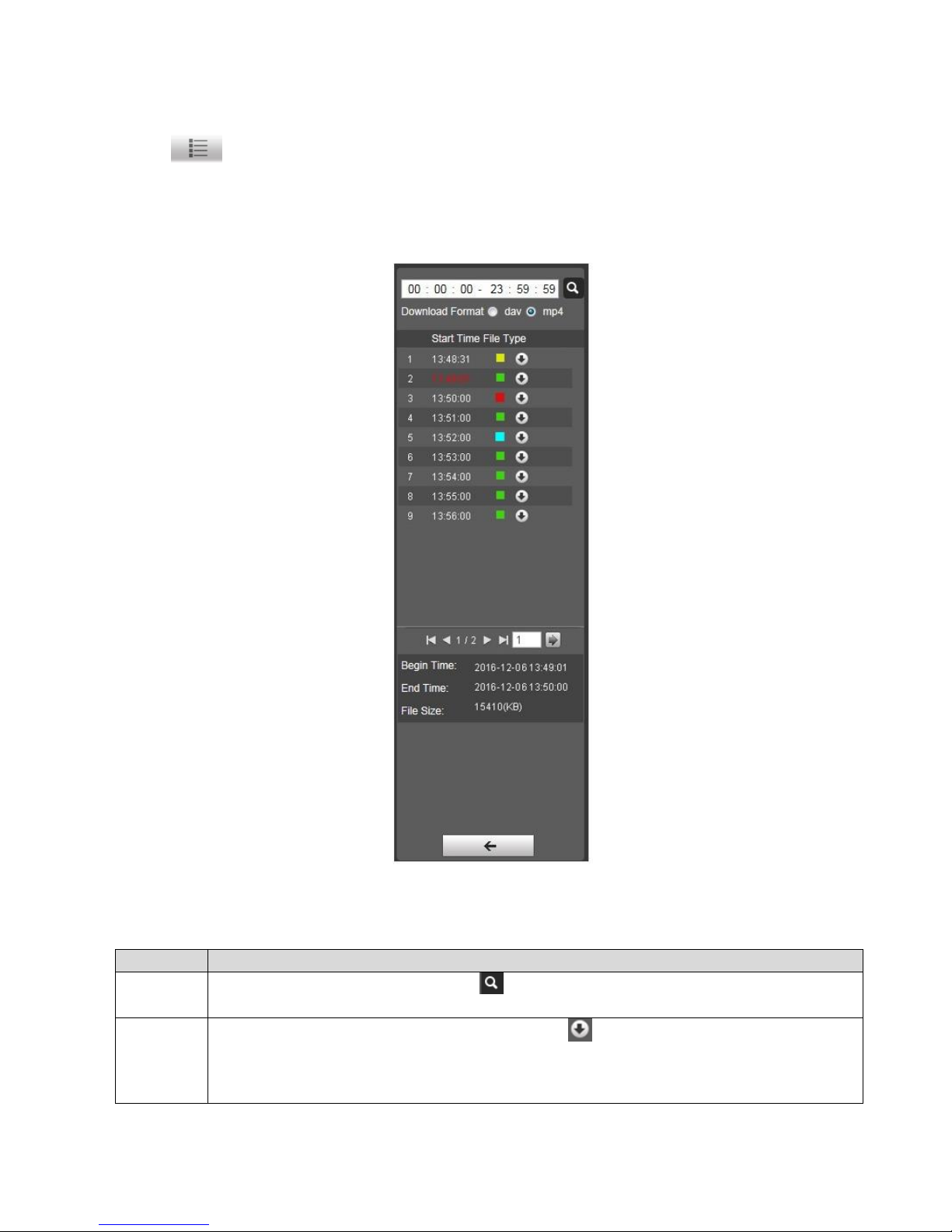
Click the in the file list, the record file of the selected date will be displayed in the list, double
click the file in the list, which is shown in Figure 3-11.
The system plays the double-clicked file, and at the same time it shown file size, begin time and end
time. Please refer to Table 3-7 for more details.
Figure 3-11
Operation
Note
Search
Input begin time and end time, click .
Search all the record files between begin time and end time.
Download
Select "Record Format" as "dav" or "mp4", click .
The file is downloaded to the designated storage path. Please refer to "4.1.2.5 Set
Storage path" for more details.
Note
Operation
Note
The system fails to support download and play video at the same time.
Back
Click to return to calendar interface.
Table 3-7
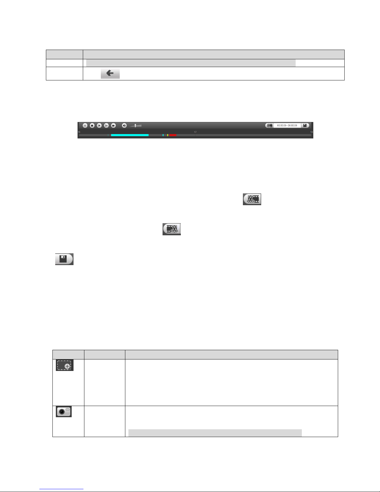
3.2.1.4 Video Clip
Clip some piece of video and save it to the designated storage path, which is shown in Figure 3-12.
Figure 3-12
Step 1
Select "Record Format" as "dav" or "mp4".
Step 2
Click on the progress bar and select the begin tine of cut video, click and begin clipping.
Step 3
Click to select end time of cut video, click to finish clipping.
Step 4
Click .
The system will prompt that it can't playback and download at the same time.
Step 5
Click "OK" and the system will disable playback, and the clipped file will be saved to designated storage
path. Please refer to "4.1.2.5 Set Storage Path" for more details.
3.2.1.5 Aux Function
The aux function of playback includes digital zoom and snapshot, please refer to Table 3-8 for more
details.
Icon
Function
Note
Digital
zoom
It supports following two types of operation to zoom video image:
Click the icon and zoom in the selected area of the video image,
click right button to recover original status. Drag the image under
zoom in status, you can check images of other areas.
Click the icon and scroll the mouse wheel to zoom video image.
Snapshot
Click the icon and capture one picture of the video, and save it into
the designated storage path.
Note
Please refer to "4.1.2.5 Set Storage Path" for more details.
 Loading...