

Dahua PFS4218-16GT-190, PFS4226-24GT-360, PFS4218-16GT-240, PFS4226-24GT-240 Web Config Manual

16/24-Port PoE
Gigabit Managed Switch
Web Config Manual
V1.0.0

Mandatory actions to be taken towards cybersecurity
1. Change Passwords and Use Strong Passwords:
The number one reason systems get “hacked” is due to having weak or default passwords. It is
recommended to change default passwords immediately and choose a strong password whenever
possible. A strong password should be made up of at least 8 characters and a combination of special
characters, numbers, and upper and lower case letters.
2. Update Firmware
As is standard procedure in the tech-industry, we recommend keeping NVR, DVR, and IP camera
firmware up-to-date to ensure the system is current with the latest security patches and fixes.
“Nice to have” recommendations to improve your network security
1. Enable HTTPS/SSL:
Set up an SSL Certificate to enable HTTPS. This will encrypt all communication between your devices
and recorder.
2. Forward Only Ports You Need:
● Only forward the HTTP and TCP ports that you need to use. Do not forward a huge range of numbers
to the device. Do not DMZ the device's IP address.
● You do not need to forward any ports for individual cameras if they are all connected to a recorder on
site; just the NVR is needed.
3. Limit Features of Guest Accounts:
If your system is set up for multiple users, ensure that each user only has rights to features and functions
they need to use to perform their job.
4. SNMP:
Disable SNMP if you are not using it. If you are using SNMP, you should do so only temporarily, for
tracing and testing purposes only.
5. Multicast:
Multicast is used to share video streams between two recorders. Currently there are no known issues
involving Multicast, but if you are not using this feature, deactivation can enhance your network security.
6. Check the Log:
If you suspect that someone has gained unauthorized access to your system, you can check the system
log. The system log will show you which IP addresses were used to login to your system and what was
accessed.
7. Physically Lock Down the Device:
Ideally, you want to prevent any unauthorized physical access to your system. The best way to achieve
this is to install the recorder in a lockbox, locking server rack, or in a room that is behind a lock and key.
Cybersecurity Recommendations
Cybersecurity Recommendations I
Name
Model
16-Port PoE Gigabit Managed Switch (190 W)
PFS4218-16GT-190
16-Port PoE Gigabit Managed Switch (240 W)
PFS4218-16GT-240
24-Port PoE Gigabit Managed Switch (240 W)
PFS4226-24GT-240
24-Port PoE Gigabit Managed Switch (360 W)
PFS4226-24GT-360
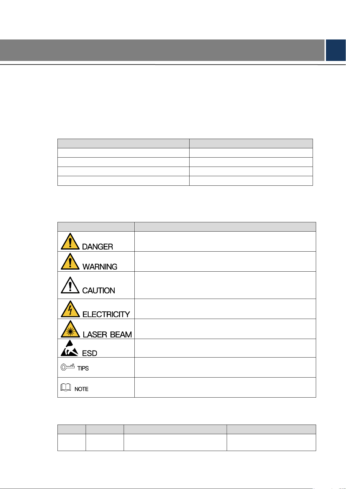
Signal Words
Meaning
Indicates a high potential hazard which, if not avoided, will result in
death or serious injury.
Indicates a medium or low potential hazard which, if not avoided,
could result in slight or moderate injury.
Indicates a potential risk which, if not avoided, could result in
property damage, data loss, lower performance, or unpredictable
result.
Indicates dangerous high voltage.
Take care to avoid coming into contact with electricity.
Indicates a laser radiation hazard.
Take care to avoid exposure to a laser beam.
Electrostatic Sensitive Devices.
Indicates a device that is sensitive to electrostatic discharge.
Provides methods to help you solve a problem or save you time.
Provides additional information as the emphasis and supplement to
the text.
No.
Version
Revision Content
Release Time
1
V1.0.0
First Release.
August 9, 2018
Foreword
General
This Web Config Manual (hereinafter referred to be "the Manual"), introduces operations on
web interface of 16/24-Port PoE Gigabit Managed Switch.
Models
Safety Instructions
The following categorized signal words with defined meaning might appear in the Manual.
Revision History
Foreword II

Privacy Protection Notice
As the device user or data controller, you might collect personal data of others' such as face,
fingerprints, car plate number, Email address, phone number, GPS and so on. You need to be
in compliance with the local privacy protection laws and regulations to protect the legitimate
rights and interests of other people by implementing measures include but not limited to:
providing clear and visible identification to inform data subject the existence of surveillance
area and providing related contact.
About the Manual
The Manual is for reference only. If there is inconsistency between the Manual and the
actual product, the actual product shall prevail.
We are not liable for any loss caused by the operations that do not comply with the Manual.
The Manual would be updated according to the latest laws and regulations of related
regions. For detailed information, see the paper User's Manual, CD-ROM, QR code or our
official website. If there is inconsistency between paper User's Manual and the electronic
version, the electronic version shall prevail.
All the designs and software are subject to change without prior written notice. The product
updates might cause some differences between the actual product and the Manual. Please
contact the customer service for the latest program and supplementary documentation.
There still might be deviation in technical data, functions and operations description, or
errors in print. If there is any doubt or dispute, please refer to our final explanation.
Upgrade the reader software or try other mainstream reader software if the Guide (in PDF
format) cannot be opened.
All trademarks, registered trademarks and the company names in the Manual are the
properties of their respective owners.
Please visit our website, contact the supplier or customer service if there is any problem
occurred when using the device.
If there is any uncertainty or controversy, please refer to our final explanation.
Foreword III

Important Safeguards and Warnings
The Manual helps you to use our product properly. To avoid danger and property damage, read
the Manual carefully before using the product, and we highly recommend you to keep it well for
future reference.
Operating Requirements
Do not expose the device directly to the sunlight, and keep it away from heat.
Do not install the device in the damp environment, and avoid dust and soot.
Make sure the device is in horizontal installation, and install the device on solid and flat
surface to avoid falling down.
Avoid liquid spattering on the device. Do not place object full of liquid on the device to
avoid liquid flowing into the device.
Install the device in the well-ventilated environment. Do not block the air vent of the device.
Use the device at rated input and output voltage.
Do not dissemble the device without professional instruction.
Transport, use, and store the device in allowed ranges of humidity and temperature.
Power Supply Requirements
Use the battery properly to avoid fire, explosion, and other dangers.
Replace the battery with battery of the same type.
Use locally recommended power cord in the limit of rated specifications.
Use the standard power adapter. We will assume no responsibility for any problems
caused by nonstandard power adapter.
The power supply shall meet the SELV requirement. Use the power supply that conforms
to Limited Power Source, according to IEC60950-1. Refer to the device label.
Adopt GND protection for I-type device.
The coupler is the disconnecting apparatus. Keep it at the angle for easy to operate.
Important Safeguards and Warnings IV

Cybersecurity Recommendations ........................................................................................................... I
Foreword ................................................................................................................................................... II
Important Safeguards and Warnings .................................................................................................... IV
1 Overview ................................................................................................................................................. 1
2 Login the Switch .................................................................................................................................... 2
3 General Settings .................................................................................................................................... 3
Device Information ........................................................................................................................ 3 3.1
Local .............................................................................................................................................. 3 3.2
VLAN ............................................................................................................................................. 4 3.3
Aggregation ................................................................................................................................... 5 3.4
VLAN Interface .............................................................................................................................. 7 3.5
4 Advanced Settings ................................................................................................................................ 9
Configuration ................................................................................................................................. 9 4.1
4.1.1 System ................................................................................................................................ 9
4.1.2 Port ................................................................................................................................... 13
4.1.3 DHCP ................................................................................................................................ 14
4.1.4 Security ............................................................................................................................. 19
4.1.5 Aggregation ....................................................................................................................... 41
4.1.6 Spanning Tree .................................................................................................................. 43
4.1.7 IGMP Snooping ................................................................................................................ 49
4.1.8 LLDP ................................................................................................................................. 51
4.1.9 PoE ................................................................................................................................... 54
4.1.10 MAC Table ...................................................................................................................... 55
4.1.11 VLANs ............................................................................................................................. 56
4.1.12 Mirroring .......................................................................................................................... 57
4.1.13 Serial Config ................................................................................................................... 58
Monitor ........................................................................................................................................ 58 4.2
4.2.1 System .............................................................................................................................. 58
4.2.2 Ports .................................................................................................................................. 60
4.2.3 DHCP ................................................................................................................................ 63
4.2.4 Security ............................................................................................................................. 65
4.2.5 Aggregation ....................................................................................................................... 70
4.2.6 Spanning Tree .................................................................................................................. 70
4.2.7 IGMP Snooping ................................................................................................................ 71
4.2.8 LLDP ................................................................................................................................. 72
4.2.9 PoE ................................................................................................................................... 74
4.2.10 MAC Table ...................................................................................................................... 74
4.2.11 VLANs ............................................................................................................................. 75
Diagnostics .................................................................................................................................. 75 4.3
4.3.1 Ping ................................................................................................................................... 76
4.3.2 Ping6 ................................................................................................................................. 76
Maintenance ................................................................................................................................ 76 4.4
Table of Contents
Table of Contents V

4.4.1 Restart Device .................................................................................................................. 76
4.4.2 Factory Defaults ................................................................................................................ 77
4.4.3 Software ............................................................................................................................ 77
4.4.4 Configuration .................................................................................................................... 78
Table of Contents VI

The 16/24-Port PoE Gigabit Managed Switch supports web access. You can visit the switch on
web browser, and configure and manage the switch.
1 Overview
Overview 1
Before login, make sure:
You already configure the IP address of the switch. By default, the IP address of VLAN 1 is
192.168.1.110.
The PC with web browser is connected to the network, and the PC can ping the switch
successfully.
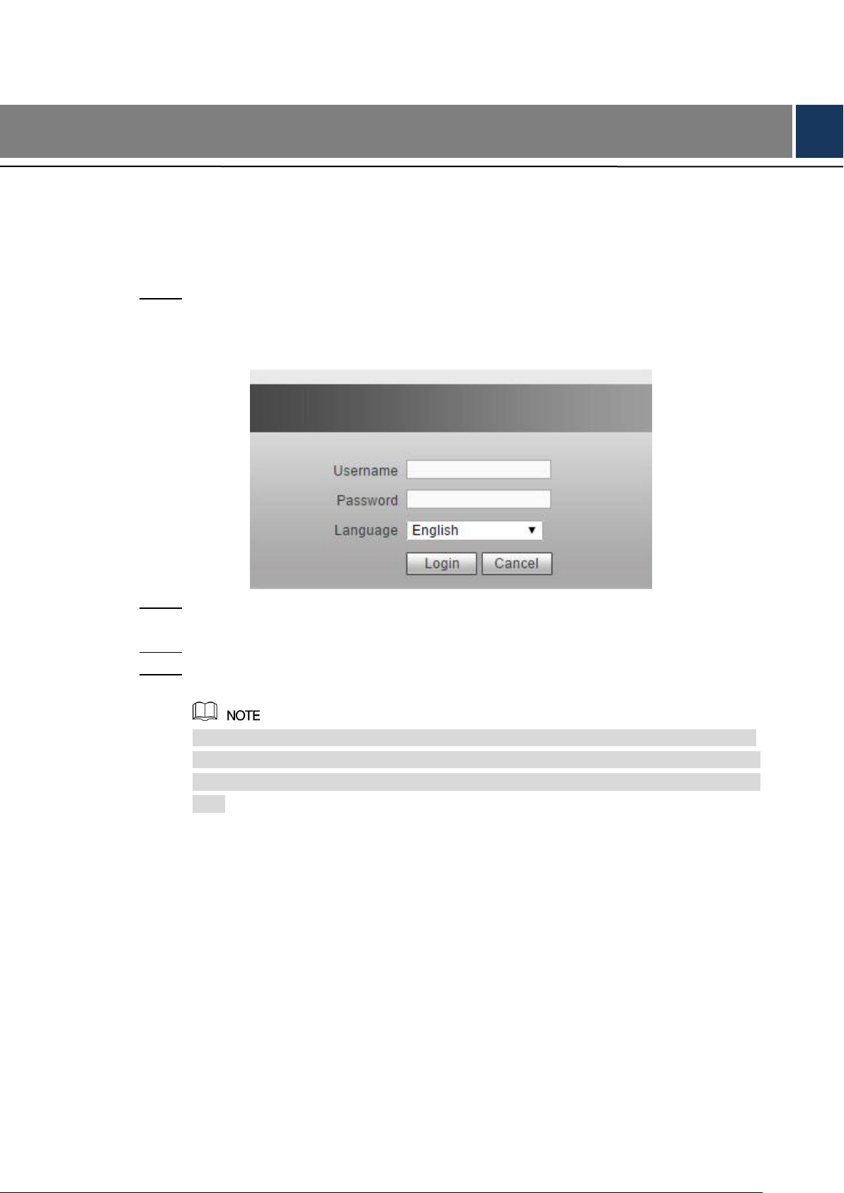
Input the IP address of the switch in the address bar of the web browser. The IP Step 1
address is 192.168.1.110 by default, and press Enter key on the keyboard.
See Figure 2-1 for login interface.
2 Login the Switch
Web login interface Figure 2-1
Input user name and password. The user name and the password are “admin” by Step 2
default.
Select the language. Step 3
Click Login. Step 4
The web service interface is displayed.
After first time login, you need to modify the password. The new password can be set
from 8 characters through 32 characters and contains at least two types from number,
letter, and special characters (excluding"'", """, ";", ":" and "&"). Modify the password in
time.
Login the Switch 2
Parameter
Description
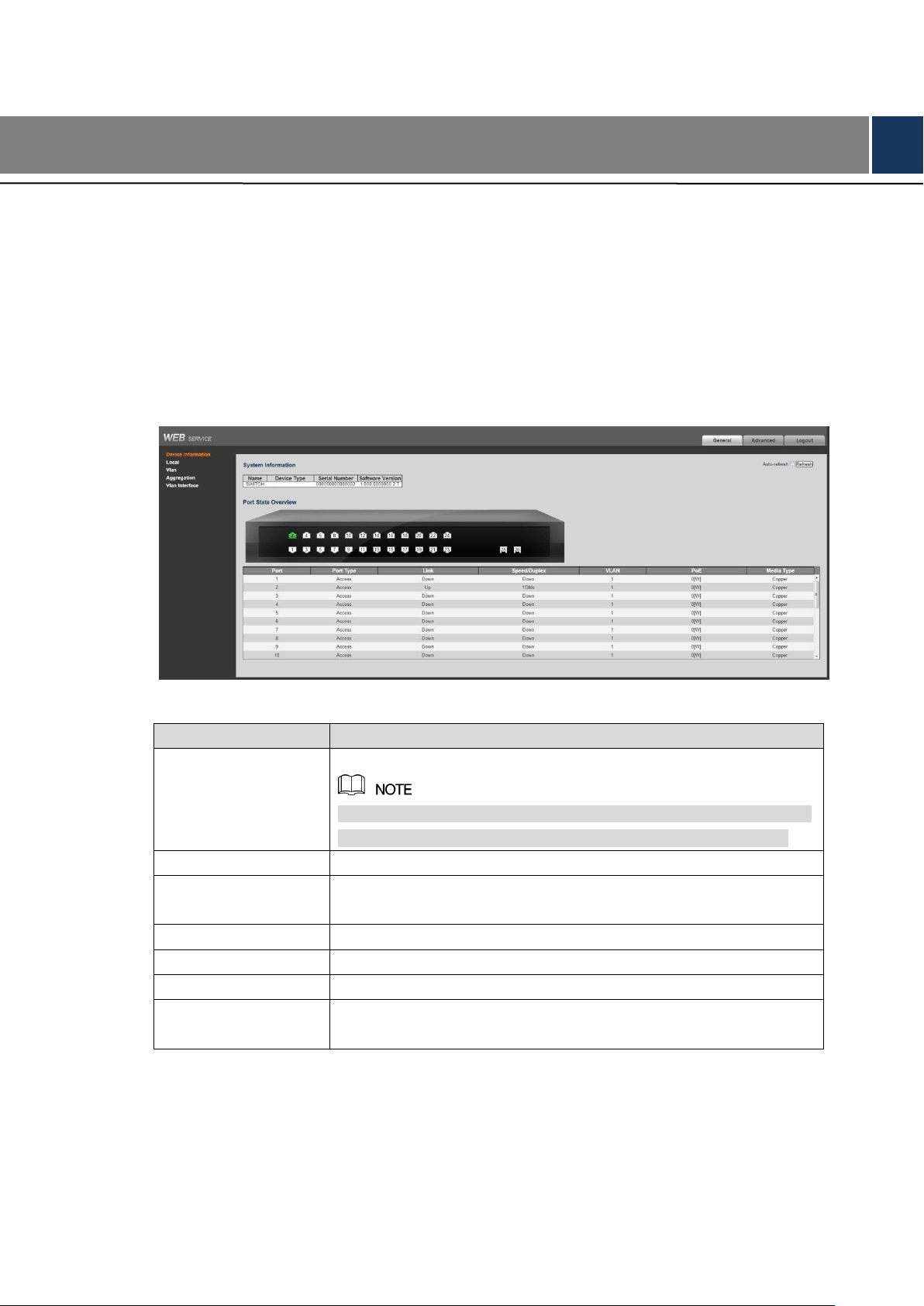
Port
Display all the ports.
This switch contains 16/24 ports. Port quantity might vary depending
on the model you purchased, and the actual product shall govern.
Port Type
Three types: Access, Hybrid, and Trunk.
Link
Two link states: Up, Down. Up indicated the port is connected
successfully, and Down indicates the port is not connected.
Speed/Duplex
Display the port rate and the duplex mode.
VLAN
Display the port VLAN. By default, it is VLAN 1.
PoE
Display the PoE power of the port.
Media Type
Two media types: Copper, Fiber. Copper is the RJ-45 port, and Fiber
is the fiber port.
3 General Settings
Device Information 3.1
You can view the Name, Device Type, Serial Number, and Software Version of the device. And
you can view the port status and port information.
Select General > Device Information, and you can view the System Information and Port
State Overview. See Figure 3-1. In Port Status Overview, if the port is displayed as green, it is
connected successfully. And if the port is displayed as white, it is not connected. See Table 3-1
for details about port information.
Device information Figure 3-1
Table 3-1 Port information
Local 3.2
You can set the system name, IP address, and address mask length.
Select General > Local, and the Local interface is displayed. See Figure 3-2.
General Settings 3

Local Figure 3-2
VLAN 3.3
Add the port to the VLAN, and configure the VLAN. By default, the port belongs to VLAN1.
Select General > Vlan. Step 1
VLAN interface is displayed. See Figure 3-3.
General Settings 4
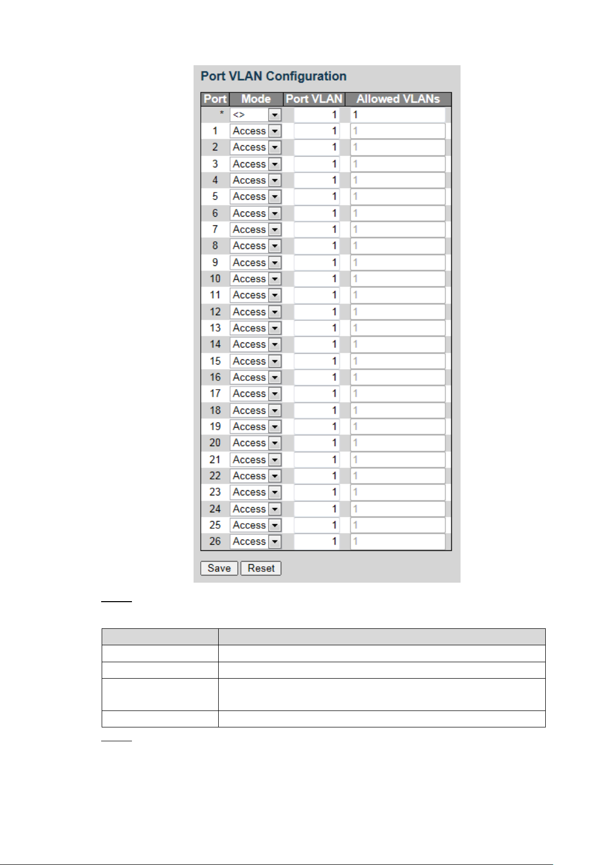
Port VLAN configuration Figure 3-3
Parameter
Description
Port
Display all the ports.
Mode
Three modes: Access, Hybrid, and Trunk.
Port VLAN
Add the port to a VLAN. By default, the port belongs to VLAN 1. It
ranges from 1 through 4094.
Allowed VLANs
Set the allowed VLAN.
Configure the port VLAN parameters. See Table 3-2. Step 2
Table 3-2 Port VLAN configuration parameter
Click Save. Step 3
Aggregation 3.4
Add the port to the aggregation. See “4.1.5 Aggregation” for details.
General Settings 5
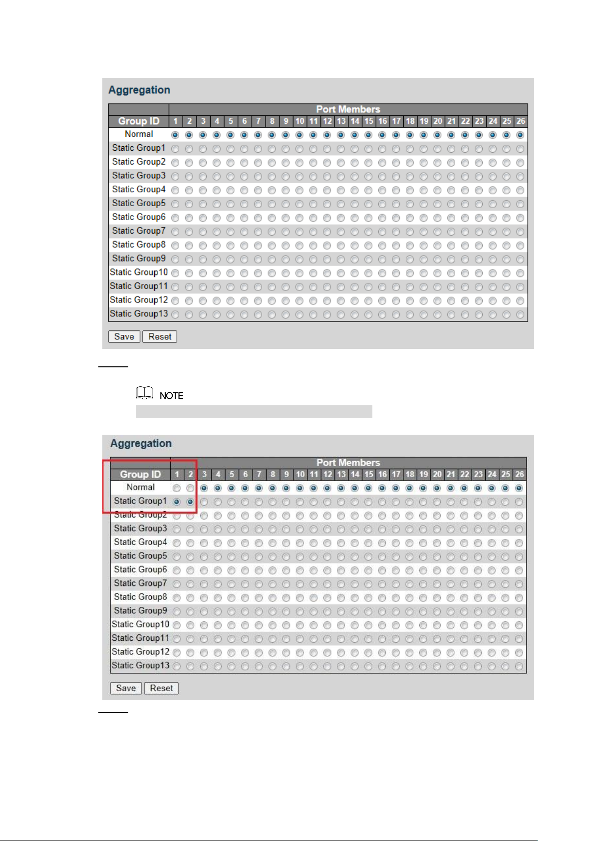
Select General > Aggregation, and the Aggregation interface is displayed. See Figure 3-4.
Aggregation Figure 3-4
Add the port member to the static group. For example, add port 1 and port 2 to Static Step 1
Group 1. See Figure 3-5.
Up to 13 static groups can be set at the same time.
Static group Figure 3-5
Click Save. Step 2
The port 1 and port 2 form the logical port.
General Settings 6
VLAN Interface 3.5
Parameter
Description
VLAN
Input VLAN number.
IP Address
Set the IP address of the VLAN interface.
Mask Length
Set the mask length of the VLAN interface.
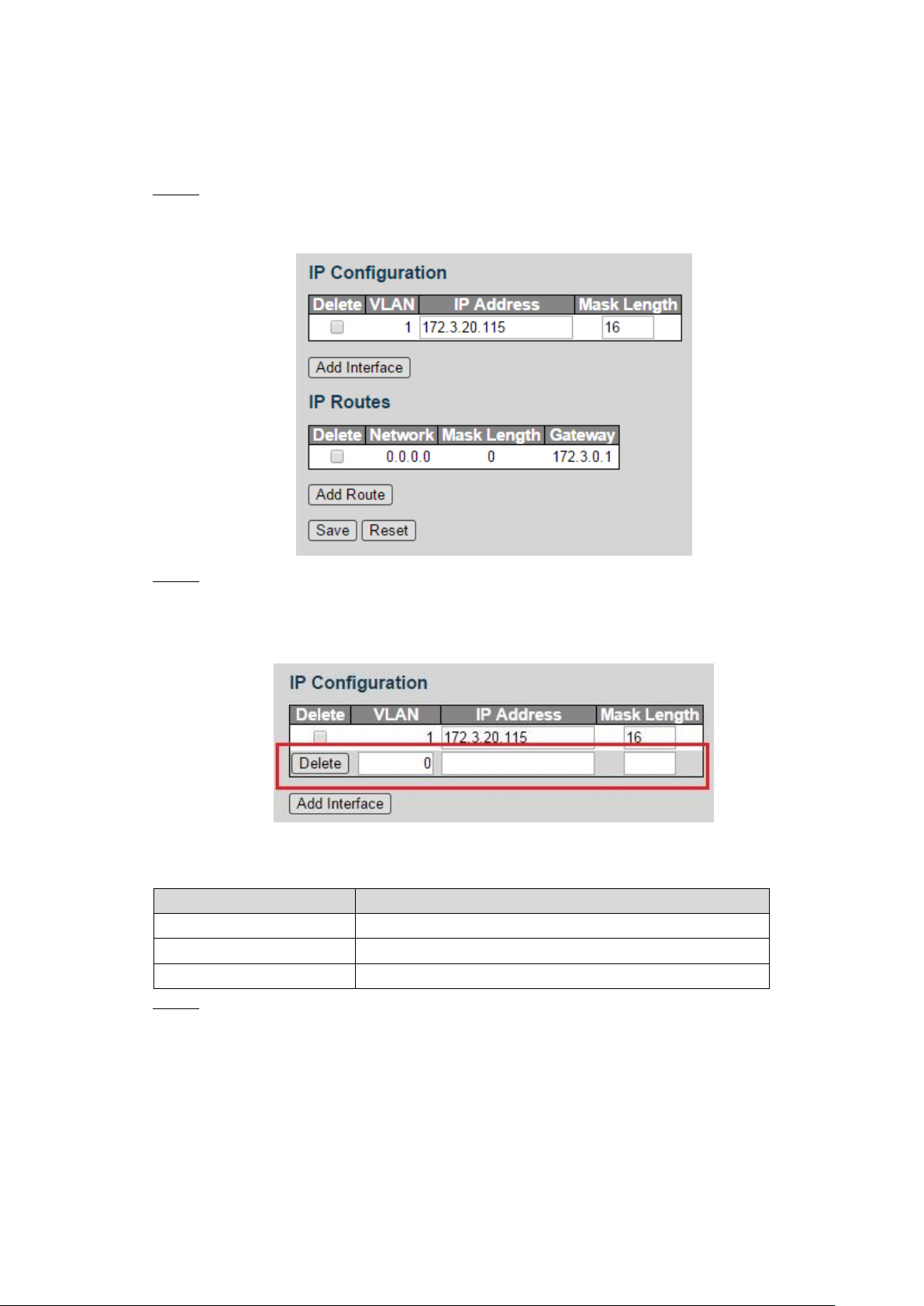
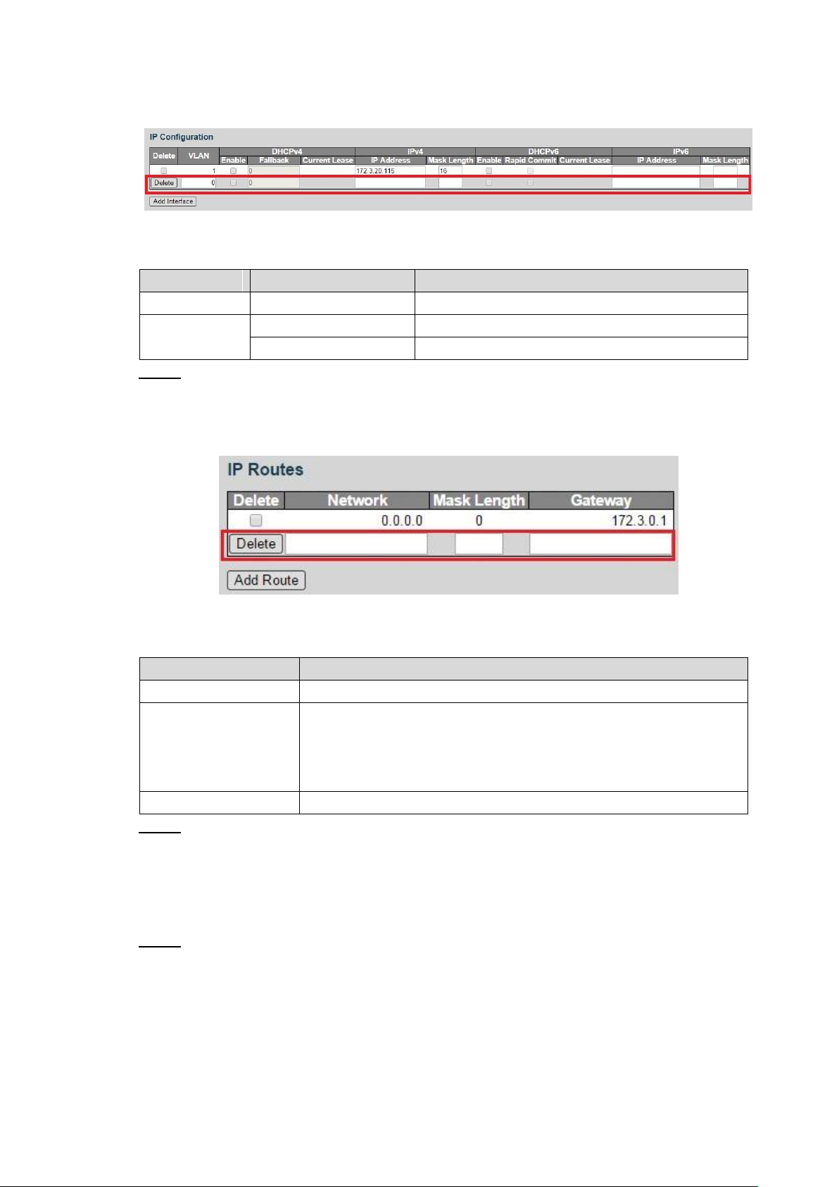
You can add the IP address for VLAN interface, and add new IP route. See “4.1.1.2 VLAN
Interface” for configuration details.
Select General > Vlan Interface. Step 1
VLAN interface is displayed. See Figure 3-6.
VLAN interface Figure 3-6
Add the VLAN interface. Step 2
1) Click Add Interface.
A new record is added. See Figure 3-7.
2) Set the parameters. See Table 3-3.
Table 3-3 VLAN interface
VLAN interface Figure 3-7
Add the IP route. Step 3
1) Click Add Routes.
A new record is added. See Figure 3-8.
General Settings 7
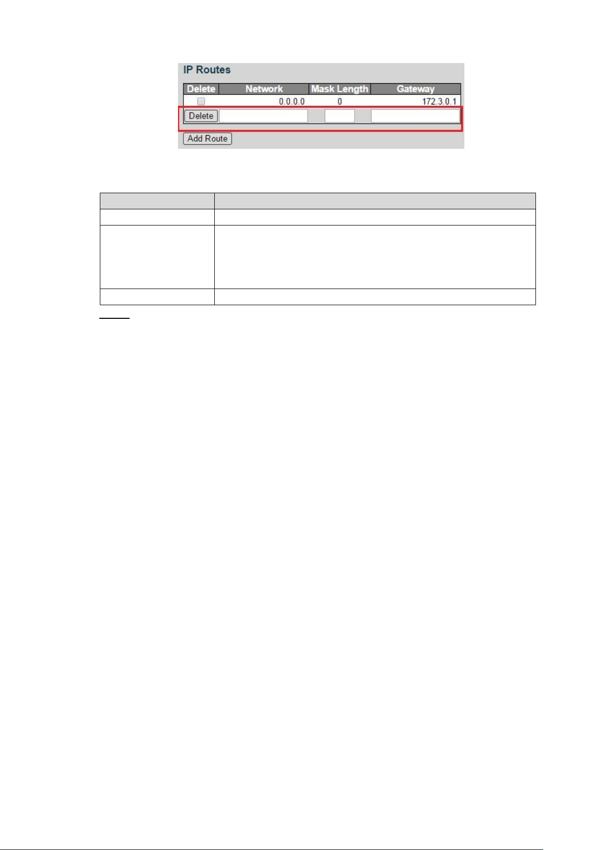
2) Set the parameters. See Table 3-4.
Parameter
Description
Network
It is the destination address of the IP packet.
Mask Length
Mask length, with destination address, is to identify the IP address of
the destination host or the route. After logical AND between
destination address and network mask, you can get the IP address of
the destination host or the route.
Gateway
The gateway IP address of the route.
Table 3-4 IP routes
Click Save. Step 4
IP routes Figure 3-8
General Settings 8
4 Advanced Settings
Configuration 4.1
4.1.1 System
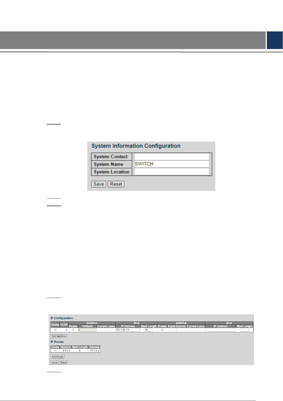
4.1.1.1 Information
You can set the system contact, system name, and system location.
Select Advanced > Configuration > System > Information.
Step 1
The Information interface is displayed. See Figure 4-1.
System information configuration Figure 4-1
Set the System Contact, System Name, and System Location. Step 2
Click Save. Step 3
4.1.1.2 VLAN Interface
The hosts belong to different VLANs cannot communicate. Route or the layer 3 switch is
needed for forwarding. The switch supports layer 3 forwarding through VLAN interface.
VLAN interface is the virtual interface of layer 3 mode, for layer 3 communication between the
VLANs. It is not the physical entity on the device. Every VLAN is related to a VLAN interface,
and the VLAN interface can forward packet for the VLAN. Generally, because the VLAN can
isolate the broadcasting domain, every VLAN corresponds to a network segment. VLAN
interface is the gateway of the network segment, and it supports layer 3 forwarding for the
packet based on IP address.
Select Advanced > Configuration > System > Vlan Interface. Step 1
VLAN interface is displayed. See Figure 4-2.
VLAN interface Figure 4-2
Add the VLAN interface. Step 2
Advanced Settings 9
1) Click Add Interface.
Parameter
Sub-parameter
Description
VLAN
-
Input VLAN number.
IPv4
IP Address
Set the IP address of the VLAN interface.
Mask Length
Set the mask length of the IP address.
Parameter
Description
Network
It is the destination address of the IP packet.
Mask Length
Mask length, with destination address, is to identify the IP address of
the destination host or the route. After logical AND between
destination address and network mask, you can get the IP address of
the destination host or the route.
Gateway
The gateway IP address of the route.
A new record is added. See Figure 4-3.
Figure 4-3
2) Set the parameters. See Table 4-1.
Table 4-1 VLAN interface
Add IP route. Step 3
1) Click Add Route.
A new record is added. See Figure 4-4.
VLAN interface
IP routes Figure 4-4
4.1.1.3 NTP
Enable NTP function, and the switch can synchronize with the network time automatically.。
2) Set the parameters. See Table 4-2.
Table 4-2 IP routes
Click Save. Step 4
Select Advanced > Configuration > System > NTP. Step 1
NTP Configure interface is displayed. See Figure 4-5.
Advanced Settings 10
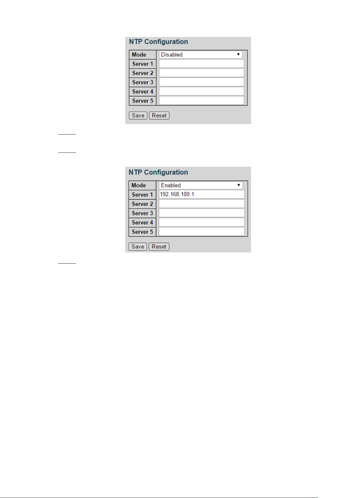
Select the mode as Enabled to enable the NTP service. By default, the mode is Step 2
Disabled.
Set the IP address of the NTP server. See Figure 4-6. Step 3
NTP configuration (1) Figure 4-5
NTP configuration (2) Figure 4-6
Click Save. Step 4
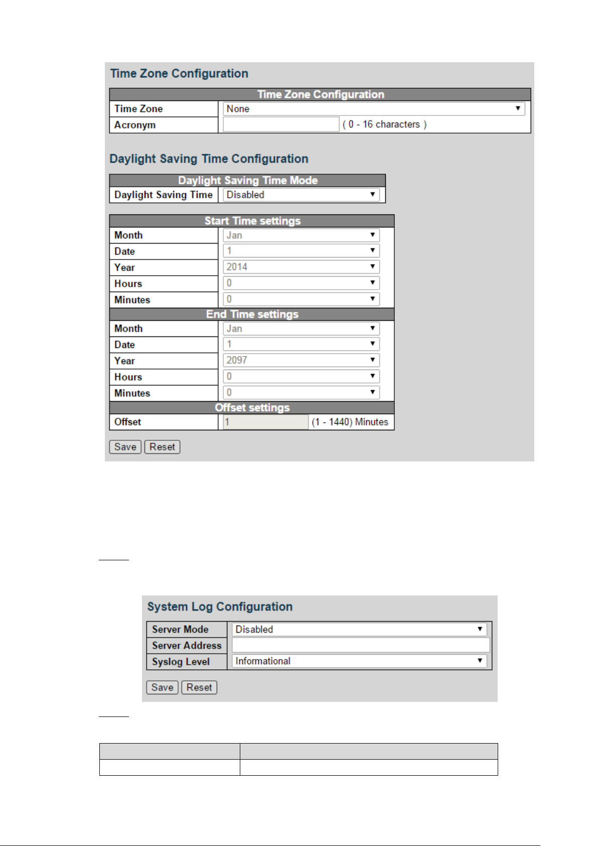
4.1.1.4 Time
You can set the time zone and daylight saving time.
Select Advanced > Configuration > System > Time. The Time settings interface is displayed.
See Figure 4-7.
The switch can synchronize with the time of server 1.
Advanced Settings 11
Time settings Figure 4-7
Parameter
Description
Server Mode
Select the server mode: Disabled or Enabled.
4.1.1.5 Log
You can configure the system log information, including Server Mode, Server Address, and
System Log Level.
Select Advanced > Configuration > System > Log. Step 1
The System Log Configuration interface is displayed. See Figure 4-8.
System log configuration Figure 4-8
Set the parameters. See Table 4-3. Step 2
Table 4-3 System log configuration
Advanced Settings 12
Parameter
Description
Server Address
Input the IP address of the log server.
System Log Level
Select the system log lever, including:
Error
Warning
Notice
Informational
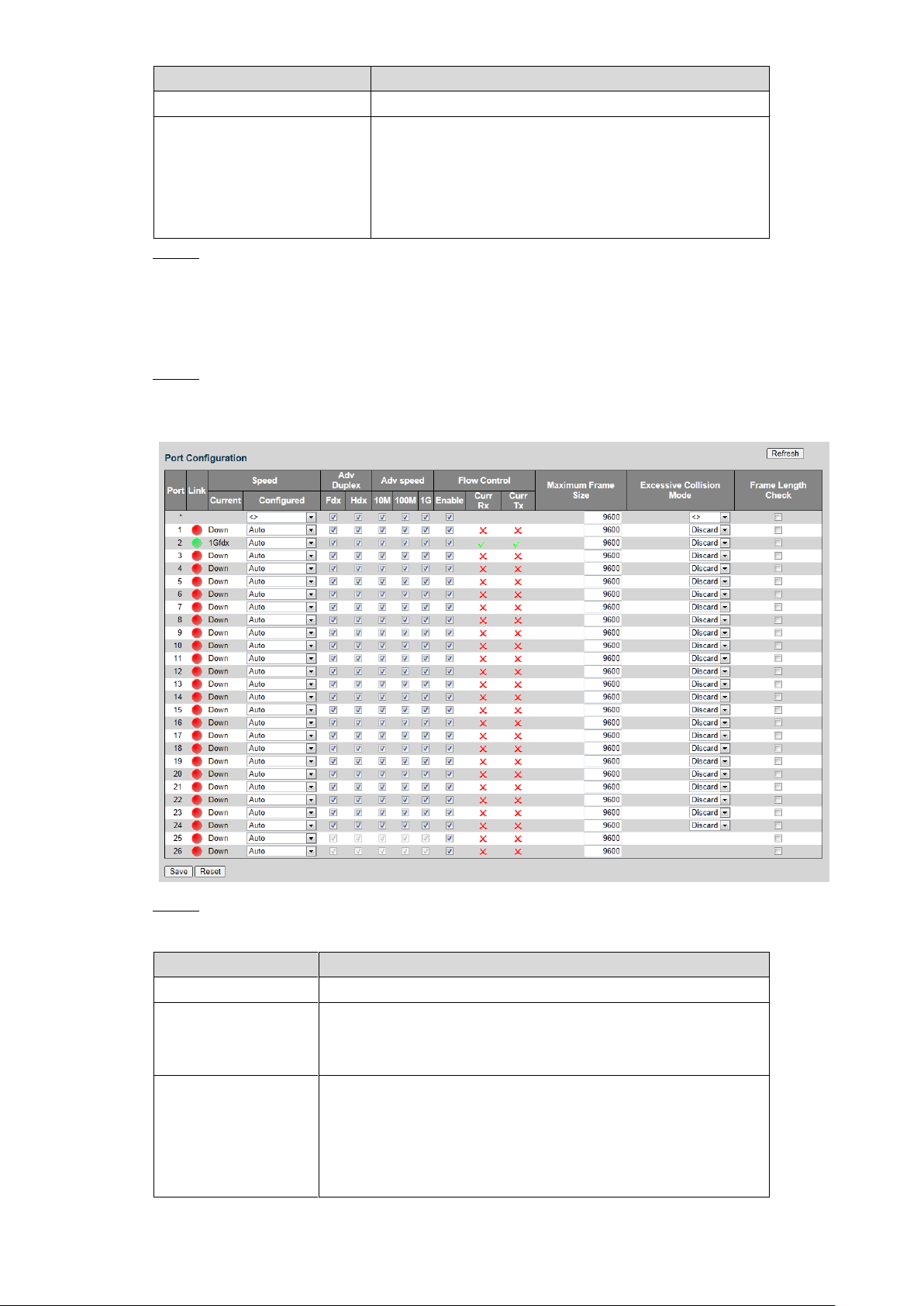
4.1.2 Port
Parameter
Description
Port
Display all the ports.
Link
If the port link is displayed as green, it is connected
successfully. And if the port link is displayed as red, it is not
connected.
Speed
Including Current and Configured. In Current list, if it is
displayed as Down, the port is not connected, and if it is
displayed as a certain speed, the port is connected
successfully. In Configured list, you can set the speed from
the drop-down list.
You can set the port parameters, including speed, duplex, flow control, and so on.
Click Save. Step 3
Select Advanced > Configuration > Port. Step 1
The Port Configuration interface is displayed. See Figure 4-9.
Port configuration Figure 4-9
Set the parameters. See Table 4-4. Step 2
Table 4-4 Port parameter
Advanced Settings 13
Parameter
Description
Duplex
Set the duplex of the port. Full duplex (Fdx) and half duplex
(Hdx) are selectable.
Adv Speed
Set the average speed of the port. 10 M, 100 M, and 1 G are
selectable.
Flow Control
You can select Enable to enable flow control function.
Maximum Frame
Size
Set the Maximum frame size.
Excessive Collision
Mode
Select excessive collision mode from the drop-down list.
Frame Length
Check
Select the checkbox to enable the function.
Click Save. Step 3
4.1.3 DHCP
4.1.3.1 Server
DHCP Server is the server for managing DHCP standard in the specific network. DHCP Server
is to allocate IP address for the workstation and make sure that the IP address for every
workstation is different. DHCP Server simplifies the network management task which should be
done manually before.
Generally, in the following scenes, DHCP Server is adopted to allocate IP address.
The network scale is large. The workload is too heavy if manually configured, and
centralized management for network will be difficult.
The quantity of PC is larger than the quantity of IP address in the network, and it is
impossible to allocate a static IP address for every PC. For example, the user quantity that
can access network at the same time is limited by ISP, and the user needs to acquire the IP
address dynamically.
Only a small number of PC need the static IP address, and most of the PC do not need the
static IP address.
There are three parts of DHCP Server configuration: address pool configuration, mode
configuration, and excluded IP configuration.
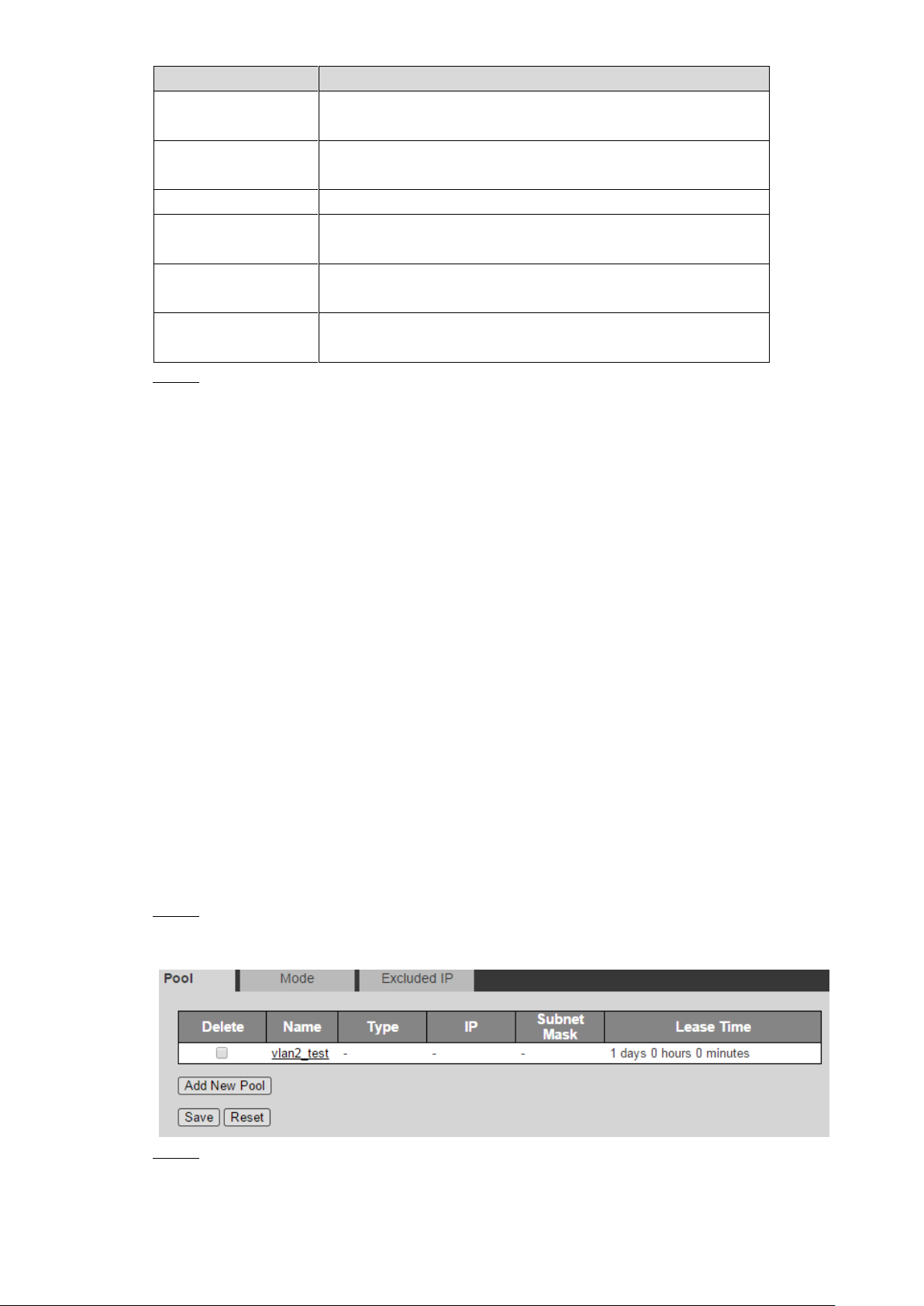
Select Advanced > Configuration > DHCP > Server. Step 1
Address pool configuration interface is displayed. See Figure 4-10.
Add a new address pool. Step 2
1) Click Add New Pool.
A new record is added. See Figure 4-11.
Address pool Figure 4-10
Advanced Settings 14
Add a new pool Figure 4-11
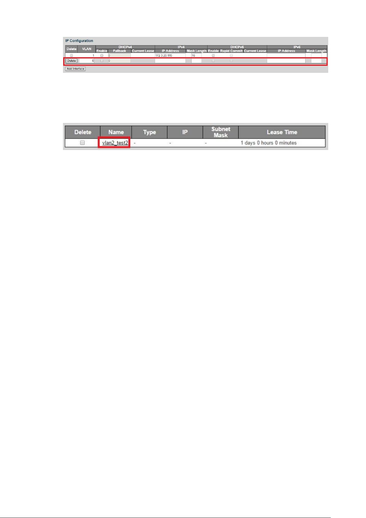
2) Input the pool name. For example, vlan2_test2.
3) Click Save.
4) Click the pool name link. See Figure 4-12.
DHCP Pool Configuration interface is displayed. See Figure 4-13.
Name link Figure 4-12
Advanced Settings 15
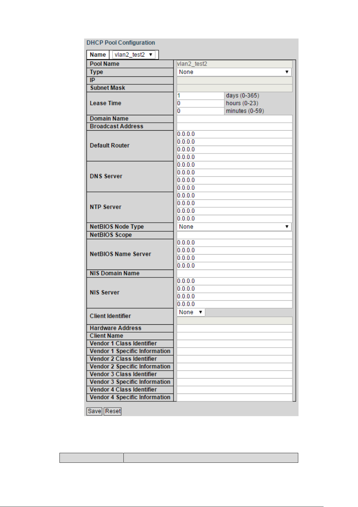
DHCP pool configuration Figure 4-13
Parameter
Description
5) Set the parameters in DHCP Pool Configuration interface. See Figure 4-13. And
see Table 4-5 for details about the parameters.
Table 4-5 DHCP pool configuration parameter
Advanced Settings 16
Parameter
Description
Type
Two types: network and host.
Network: a segment of IP address.
Host: a specific IP address.
IP
Input the IP address of the host or the network.
Subnet Mask
Input the subnet mask.
Lease Time
Input the lease time of the address pool.
Domain Name
Configure the domain name.
Broadcast Address
Configure the broadcast address.
Default Router
Configure the default gateway of the address pool.
DNS Server
Configure the server IP address of the domain name
system.
NTP Server
Configure the NTP server IP address.
6) Click Save.
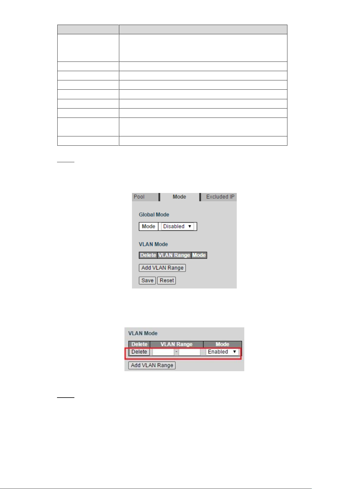
Configure the mode. Step 3
1) Click Mode tab.
The Mode interface is displayed. See Figure 4-14.
Mode Figure 4-14
2) Select the Mode as Enabled to enable DHCP Server.
3) Click Add VLAN Range.
A new record is added. See Figure 4-15.
Add VLAN range Figure 4-15
4) Input the VLAN range. For example, 2-4.
5) Click Save.
Configure the host IP address and the IP address segment. Step 4
1) Click Exclude IP tab.
Excluded IP interface is displayed. See Figure 4-16.
Advanced Settings 17
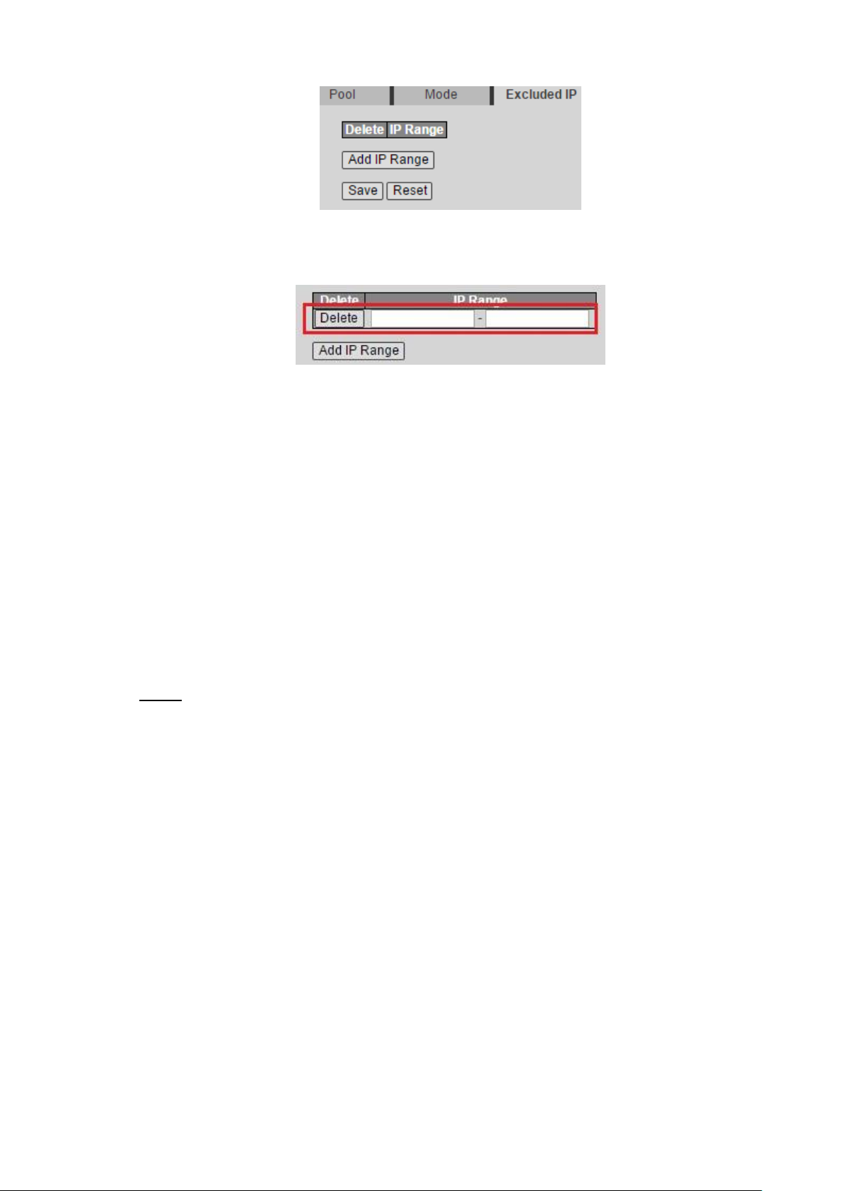
2) Click Add IP Range.
A new record is added. See Figure 4-17.
3) Input the IP address range. For example, 192.168.100.2-192.168.100.50.
4) Click Save.
4.1.3.2 DHCP Snooping
Excluded IP Figure 4-16
Add IP range Figure 4-17
DHCP Snooping is a security feature of DHCP to make sure that the client acquires the IP
address from the legal server. If there is the illegal server built up privately in the network, the
DCHP client might acquire wrong IP address and network configuration parameter, and
communication will fail. To make sure that the DHCP client acquires the IP address from the
legal DHCP Server, DHCP Snooping security mechanism supports to set the port as Trusted
and Untrusted.
The trusted port can forward the received DHCP packet normally.
The untrusted port discards the DHCP-ACK packet and the DHCP-OFFER packet by
DHCP Server.
Select Advanced > Configuration > DHCP > Snooping. Step 1
DHCP Snooping interface is displayed. See Figure 4-18.
Advanced Settings 18
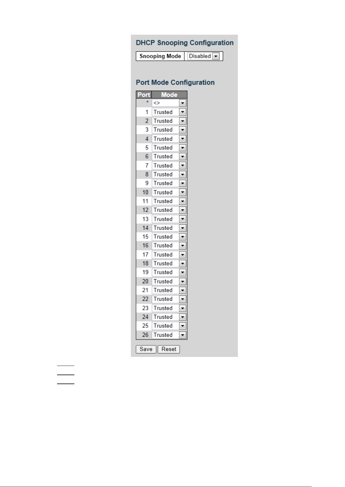
DHCP Snooping configuration Figure 4-18
Select the Snooping Mode as Enabled to enable DHCP Snooping . Step 2
Set the port as Trusted or Untrusted. Step 3
Click Save. Step 4
4.1.4 Security
4.1.4.1 Users
You can add, edit, and delete the user.
Advanced Settings 19
 Loading...