

Page 1

Network Video Decoder Quick Start Guide
V3.4.0
Page 2

i
Table of Contents
1 FRONT PANEL/REAR PANEL/INSTALLATION ...................................... 1
1.1 Check Unpacked Device ........................................................................................................ 1
1.2 Front panel ............................................................................................................................... 1
1.2.1 1/4-channel 4K High Definition &1/4-channel High Definition Series ......................... 1
1.2.2 9-channel 4K high definition (with 4 input ports) series / 9-channel 4K high definition
series /9-channel High Definition Series/16-channel High Definition Series............................ 2
1.2.3 12-channel 4K high definition series/12-channel 4K high definition (with 4 input
ports) series/ 15-channel 4K high definition series/15-channel 4K high definition (with 4
input ports) series/ 18-channel 4K high definition series/18-channel 4K high definition (with
4 input ports) series/ 21-channel 4K high definition series/21-channel 4K high definition
(with 4 input ports) series ................................................................................................................. 3
1.3 Rear Panel ................................................................................................................................ 4
1.3.1 1-channel 4K High Definition Series ................................................................................ 4
1.3.2 4-channel 4K high definition series .................................................................................. 5
1.3.3 9-channel 4K high definition (with 4 input ports) series ................................................ 5
1.3.4 9-channel 4K high definition series .................................................................................. 6
1.3.5 1-channel High Definition Series ...................................................................................... 7
1.3.6 4-channel High Definition Series ...................................................................................... 7
1.3.7 9-channel High Definition Series ...................................................................................... 8
1.3.8 16-channel High Definition Series .................................................................................... 8
1.3.9 12-channel 4K high definition series/12-channel 4K high definition (with 4 input
ports) series/ 15-channel 4K high definition series/15-channel 4K high definition (with 4
input ports) series/ 18-channel 4K high definition series/18-channel 4K high definition (with
4 input ports) series/ 21-channel 4K high definition series/21-channel 4K high definition
(with 4 input ports) series ................................................................................................................. 9
1.4 Connection ............................................................................................................................. 12
2 OPERATION ........................................................................................... 13
2.1 Boot Up and Shut Down ....................................................................................................... 13
Page 3

ii
2.2 Login ........................................................................................................................................ 13
2.2.1 Preparation ........................................................................................................................ 13
2.2.2 Login ................................................................................................................................... 14
2.3 Main Window .......................................................................................................................... 16
Page 4

iii
Welcome
Thank you for purchasing our product!
This quick start guide will help you become familiar with our device in a very short time.
Before installation and operation please read the following safeguard and warning
carefully!
Please keep it well for future reference!
Page 5

iv
Important Safeguard and Warning
1.Electrical safety
All installation and operation here should conform to your local electrical safety
codes.
The product must be grounded to reduce the risk of electric shock.
We assume no liability or responsibility for all the fires or electrical shock caused by
improper handling or installation.
Please use three-pin power socket (with GND).
This device is to be connected only to the unit whose power feeding meets the
requirements for SELV (Safety Extra Low Voltage) and complies with Limited Power
Source according to IEC 60950-1.
We are not liable for any problems caused by unauthorized modifications or
attempted repair.
2.Installation
Do not apply power to the device before completing installation.
Do not put object on the device.
All the examination and repair work should be done by the qualified service
engineers.
3.Environment
This series device should be installed in a cool, dry place away from direct sunlight,
inflammable, explosive substances and etc.
Please guarantee sound ventilation and keep device clean.
4. Accessories
Be sure to use all the accessories recommended by manufacturer.
Before installation, please open the package and check all the components are
included.
Contact your local retailer ASAP if something is broken in your package.
RISK OF EXPLOSION IF BATTERY IS REPLACED BY AN INCORRECT TYPE.
DISPOSE OF USED BATTERIES ACCORDING TO THE INSTRUCTIONS.
Page 6
1
1 Front Panel/Rear Panel/Installation
Note:
All the installation and operations here should conform to your local electric
safety rules.
VGA cable quality and length can affect the video quality. It may result in
distorted video, noise, black margin. The video quality may vary even if you are
viewing the same video via different VGA cables.
1.1 Check Unpacked Device
When you received the device from the shipping agency, please check whether there is
any visible damage. The protective materials used for the package of the device can
protect most accidental clashes during transportation. Then you can open the box to
check the accessories.
Please check the items in accordance with the list.
Finally you can remove the protective film of the device.
The label at the bottom of the box is very important. Usually we need you to present the
serial number when we provide the service after sales.
1.2 Front panel
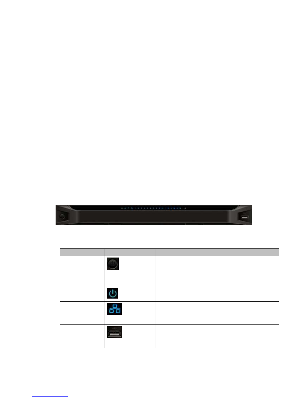
1.2.1 1/4-channel 4K High Definition &1/4-channel High Definition Series
The 1-channel 4K high definition and 1/4-channel high definition series front panel is
shown as in Figure 1-1.
Figure 1-1
Please refer to the following sheet for detailed information.
Name
Icon
Function
Power button
Press it for three seconds to boot up or shut down the
device.
Press it three times within one second, it can clear
device configuration.
Power indicator
light
The indicator light becomes on when system boots up.
Network indicator
light
The indicator light becomes on when abnormal
network event occurs (offline, IP conflict and etc.)
USB port
Connect to external USB device.
Page 7
2
Name
Icon
Function
Alarm indicator
light
The light becomes on when there is an alarm.
HDD indicator
light
N/A
IR receiver
N/A
Output indicator
light
It is to display output port working mode.
For 1-channel 4K high definition series and 1-channel
high definition series, only the first indicator light is
effective.
For 4-channel 4K high definition series and 4-channel
high definition series, only the channel 1 to channel 4
indicator lights is effective.
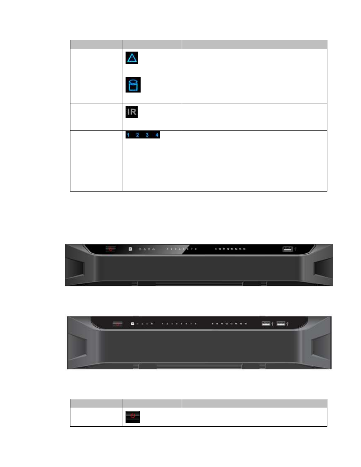
1.2.2 9-channel 4K high definition (with 4 input ports) series / 9-channel
4K high definition series /9-channel High Definition
Series/16-channel High Definition Series
The 9-channel 4K high definition (with 4 input ports) series /9-channel 4K high definition
series /9-channel high definition series front panel is shown as in Figure 1-2.
Figure 1-2
The 16-channel high definition series front panel is shown as in Figure 1-3.
Figure 1-3
Please refer to the following sheet for detailed information.
Name
Icon
Function
Power button
Press it for three seconds to boot up or shut down the
device.
Page 8
3
Name
Icon
Function
Press it three times within one second, it can clear
device configuration.
Power indicator
light
The indicator light becomes on when system boots up.
Network indicator
light
The indicator light becomes on when abnormal
network event occurs (offline, IP conflict and etc.)
USB port
Connect to external USB device.
Alarm indicator
light
The light becomes on when there is an alarm.
HDD indicator
light
N/A
IR receiver
N/A
Output indicator
light
It is to display output port working mode.
For 9-channel 4K high definition series/ 9-channel
4K high definition (with 4 input ports)
series/9-channel high definition series, only the
channel 1 to channel 9 indicator light is effective.
For 16-channel high definition series, only the
channel 1 to channel 16 indicator light is effective.
1.2.3 12-channel 4K high definition series/12-channel 4K high definition
(with 4 input ports) series/ 15-channel 4K high definition
series/15-channel 4K high definition (with 4 input ports) series/
18-channel 4K high definition series/18-channel 4K high definition
(with 4 input ports) series/ 21-channel 4K high definition
series/21-channel 4K high definition (with 4 input ports) series
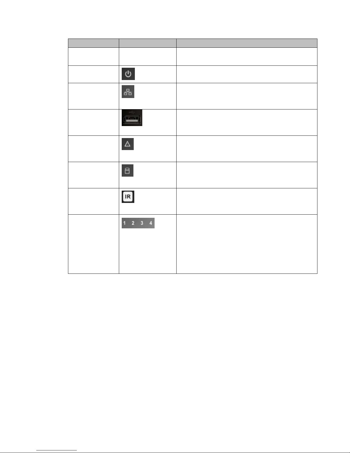
The front panel is shown as below. See Figure 1-4.
Page 9

4
Figure 1-4
Please refer to the following sheet for detailed information.
Name
Icon
Function
Power button
Press it for three seconds to boot up or shut down
the device.
IR receiver
N/A
Power indicator
light
The indicator light becomes on when system
boots up.
Alarm indicator
light
The light becomes on when there is an alarm.
Running indicator
light
The light is on when device is running.
Network indicator
light
N/A
Fan indicator light
N/A
USB port
Connect to external USB device.
1.3 Rear Panel
1.3.1 1-channel 4K High Definition Series
The rear panel is shown as below. See Figure 1-5.
Figure 1-5
Page 10

5
Please refer to the following sheet for detailed information.
SN
Port Name
SN
Port Name
SN
Port Name
1
Ground screw
hole
2
RS232 port
3
USB port
4
HDMI port
5
Network
interface(10M/100M/1
000M self-adaptive
Ethernet port)
6
VGA port
7
Audio talk output
port RCA OUT
8
Audio talk input
port RCA IN
9
4-channel alarm input,
4-channel alarm output,
RS485 port.
10
Power socket
11
Power switch
1.3.2 4-channel 4K high definition series
The rear panel is shown as below. See Figure 1-6.
Figure 1-6
Please refer to the following sheet for detailed information.
SN
Port Name
SN
Port Name
SN
Port Name
1
Ground screw hole
2
Audio output port(BNC)
3
Video output port
(BNC)
4
Audio talk input
port
5
Audio talk output
port
6
VGA port
7
HDMI output port
8
HDMI input port
9
RS232 port
10
RS232 port to control
the screen
11
Network
interface(10M/100M/1000
M self-adaptive Ethernet
port)
12
USB port
13
Alarm input, alarm
output, standard RS485
port
14
Power on-off button
15
Power socket
1.3.3 9-channel 4K high definition (with 4 input ports) series
The rear panel is shown as below. See Figure 1-7.
Page 11

6
Figure 1-7
Please refer to the following sheet for detailed information.
SN
Port Name
SN
Port Name
SN
Port Name
1
Ground screw hole
2
Power socket
3
Power on-off button
4
HDMI output port
5
RS232 port
6
USB3.0 port
7
Audio talk input
port
8
Audio talk output
port
9
Network
interface(10M/100M
/1000M
self-adaptive
Ethernet port)
10
RS232 port to control
the screen
11
Alarm input, alarm
output, standard RS485
port
12
DVI-I input port
13
HDMI input port
- - -
-
1.3.4 9-channel 4K high definition series
The rear panel is shown as below. See Figure 1-8.
Figure 1-8
Please refer to the following sheet for detailed information.
SN
Port Name
SN
Port Name
SN
Port Name
1
Ground screw
hole
2
Power socket
3
Power on-off button
4
HDMI input port
5
RS232 port
6
USB3.0 port
7
Audio talk input
port
8
Audio talk output
port
9
Network
interface(10M/100M/1000M
self-adaptive Ethernet port)
10
RS232 port to
control the
11
Alarm input, alarm
output, standard RS485
-
-
Page 12

7
screen
port
1.3.5 1-channel High Definition Series
The rear panel is shown as below. See Figure 1-9.
Figure 1-9
Please refer to the following sheet for detailed information.
SN
Port Name
SN
Port Name
SN
Port Name
1
Ground screw hole
2
Audio output port(BNC)
3
Video output port (BNC)
4
Audio talk input
port
5
Audio talk output
port
6
VGA port
7
RS232 port
8
HDMI port
9
Network
interface(10M/100M/100
0M self-adaptive
Ethernet port)
10
Relay input, relay
output, duplex RS485
port
11
Power socket
12
Power switch
1.3.6 4-channel High Definition Series
The rear panel is shown as in Figure 1-10.
Figure 1-10
Please refer to the following sheet for detailed information.
SN
Port Name
SN
Port Name
SN
Port Name
1
Ground screw hole
2
Audio output port(BNC)
3
Video output port (BNC)
4
Audio talk output
port
5
Audio talk input
port
6
VGA port
7
HDMI port
8
RS232 port
9
Network
interface(10M/100M/100
0M self-adaptive
Ethernet port)
Page 13

8
10
Relay input, relay
output, duplex RS485
port
11
Power socket
12
Power switch
1.3.7 9-channel High Definition Series
The rear panel is shown as below. See Figure 1-11.
Figure 1-11
Please refer to the following sheet for detailed information.
SN
Port Name
SN
Port Name
SN
Port Name
1
Ground screw hole
2
Power switch
3
Power socket
4
HDMI port
5
Network
interface(10M/100M/1000M
self-adaptive Ethernet port)
6
Relay input, relay
output, standard RS485
port.
7
Audio talk input
port
8
Audio talk output
port
9
Audio output port
10
RS232 port
11
VGA port
1.3.8 16-channel High Definition Series
The rear panel is shown as below. See Figure 1-12.
Figure 1-12
Page 14

9
Please refer to the following sheet for detailed information.
SN
Port Name
SN
Port Name
SN
Port Name
1
Ground screw hole
2
Power switch
3
Power socket
4
HDMI port (16)
5
VGA port (16)
6
Audio talk output port
7
Audio output port
8
Standard RS485 port
9
Audio talk input port
10
Network
interface(10M/100M/1000M
self-adaptive Ethernet port)
11
RS232 port
1.3.9 12-channel 4K high definition series/12-channel 4K high definition
(with 4 input ports) series/ 15-channel 4K high definition
series/15-channel 4K high definition (with 4 input ports) series/
18-channel 4K high definition series/18-channel 4K high definition
(with 4 input ports) series/ 21-channel 4K high definition
series/21-channel 4K high definition (with 4 input ports) series
The 21-channel 4K high definition series/21-channel 4K high definition (with 4 input ports)
series rear panel is shown as below. See Figure 1-13.
Figure 1-13
The 18-channel 4K high definition series/18-channel 4K high definition (with 4 input ports)
series rear panel is shown as below. See Figure 1-14.
Figure 1-14
The 15-channel 4K high definition series/15-channel 4K high definition (with 4 input ports)
Page 15

10
series rear panel is shown as below. See Figure 1-15.
Figure 1-15
The 12-channel 4K high definition series/12-channel 4K high definition (with 4 input ports)
series rear panel is shown as below. See Figure 1-16.
Figure 1-16
Note
For the above four series, they only have different decode card types. The rest parts
are the same.
For XX-channel 4K high definition series and XX-channel 4K high definition (with 4
input ports) series, the only difference is one series has the capture card and the
other does not have capture card. The rest parts are the same.
Main control board
The control board interface is shown as below. See Figure 1-17.
Figure 1-17
Page 16

11
Please refer to the following sheet for detailed information.
SN
Name
SN
Name
SN
Name
1
Default button
2
Main control
board power
indicator light,
system status
indicator light,
PCI-E status
indicator light
3
USB port
4
HDMI output port
5
Audio talk input port
6
Audio talk output port
7
Network port
8
Clear alarm button
9
2-channel alarm
input, 1-channel
alarm output ,
RS485 port.
10
RJ45 COM port
11
RS232 COM port
-
-
Decode card
The 3-channel decode card is shown as in Figure 1-18.
Figure 1-18
The 6-channel decode card is shown as in Figure 1-19.
Figure 1-19
Capture card
The capture card is shown as in Figure 1-20.
Page 17

12
Figure 1-20
Please refer to the following sheet for detailed information.
SN
Name
SN
Name
SN
Name
1
DVI input port
2
Backup button
3
HDMI input port
4
Indicator light
- - -
-
Note:
When you connect it to the PC network port, please use crossover cable.
When you connect it to the PC via router or switcher, please use straight cable.
1.4 Connection
Please refer to the follow figure for connection information. See Figure 1-21.
The following figure is based on the 4-channel high definition series product.
Figure 1-21
Page 18

13
2 Operation
The following operations are generally based on the 9-channel high definition
series product.
Slight different may be found in the user interface.
2.1 Boot Up and Shut Down
Boot up
Connect the device to the power and then press the power button in the rear panel. You
can see the power indicator light becomes on and device boots up.
The system is in multiple-window display mode by default.
Shut down
You can press power button in the front panel for three seconds to shut down the device.
System Restore after Power Failure
When decoder is working, if the power failure occurs, the system can automatically
connect to the front-end device and restore previous working status once the power
connection becomes normal.
2.2 Login
2.2.1 Preparation
Before log in, please make sure:
Device connection is OK.
You have set PC IP address, device IP address, subnet mask and gateway. (Please
set the IP address of the same section for the PC and device. Please input
corresponding gateway and subnet mask if there are routers.). When device booted
up normally, please input account name admin and password admin via the PC
COM port., then input net –a and then input IP, NETMASK, GATEWAY. The
command mode is: net -a [IP] [NETMASDK] [GATEWAY].
For example:
Username: admin
Password: admin
DeBug>net -a 192.168.XXX.XXX 255.255.XXX.XXX 192.168.XXX.XXX
Use order ping ***.***.***.***(Device IP address) to check connection is OK or not.
Usually the return TTL value should be less than 255.
Open IE and then input the address in the column.
WEB control can be downloaded and installed automatically. System can download
the latest Web control and remove the old one.
You can run uninstall web.bat to remove the control
Page 19

14
System is compatible with web control of WINVISTA. But you need to disable account
control item and then reboot the PC.
2.2.2 Login
Open the IE and then input the device IP address in the address column.
For example, if your device IP address is 192.168.1.100, then please input http://
192.168.1.100 in IE address column. See Figure 2-1.
Figure 2-1
System pops up warning information to ask you whether install webrec.cab control or not.
Please click yes button.
If you can’t download the ActiveX file, please modify your settings as follows. See Figure
2-2.
Input IP
address here.
Page 20

15
Figure 2-2
After installation, the interface is shown as below. See Figure 2-3.
Figure 2-3
Please input your user name and password and then click Login button.
Default factory name is admin and password is admin.
Note: For security reasons, please modify your password after you first login.
Now you can see system pops up the following dialogue box to remind you to change the
default password. See Figure 2-4.
Page 21

16
Figure 2-4
Click Yes button, you can see the Modify Password dialogue box. Please input the new
password twice and then click the Yes button. See Figure 2-5.
Click No button to remain the default password.
Figure 2-5
2.3 Main Window
After login successfully, you can go to the main interface.
For 1-channel 4K high definition series/4-channel 4K high definition series/1-channel high
definition series/4-channel high definition series, the interface will be shown as Figure 2-6.
Page 22

17
Figure 2-6
For 9-channel high definition series/16-channel high definition series, the interface is
shown as in Figure 2-7.
Figure 2-7
Page 23

18
For 4-channel 4K high definition series/ 9-channel 4K high definition series/9-channel 4K
high definition (with 4 input ports) series, the interface is shown as Figure 2-8.
Figure 2-8
For 12-channel 4K high definition series/12-channel 4K high definition (with 4 input ports)
series/ 15-channel 4K high definition series/15-channel 4K high definition (with 4 input
ports) series/ 18-channel 4K high definition series/18-channel 4K high definition (with 4
input ports) series/ 21-channel 4K high definition series/21-channel 4K high definition
(with 4 input ports) series, the interface is shown as below. See Figure 2-9.
Figure 2-9
Page 24

19
Please refer to the following sheet for detailed information.
SN
Name
SN
Name
1
System menu
2
Screen No.
3
Splicing wall
4
Bidirectional talk
5
Connected front-end device
list
6
Add/delete device
7
Playback
8
Window split
9
TV adjustment/screen
manager
10
Full-screen button
11
Refresh
12
Scheme manager/Save
13
Roam
14
Local signal
Note:
For detailed operation introduction, please refer to our resource CD included in
your package for electronic version of the User’s Manual.
This quick start guide is for reference only. All the designs and software here
are subject to change without prior written notice.
All trademarks and registered trademarks mentioned are the properties of their
respective owners.
If there is any uncertainty or controversy, please refer to the final explanation of
us.
Please visit our website or contact your local retailer for more information.
 Loading...