

Dahua NVS0104HDC, NVS0204HDC, NVS0404HDC User Manual

Dahua Network Video Server User’s Manual
Dahua Network Video Server User’s Manual
V1.0.0

Dahua Network Video Server User’s Manual
i
Table of Contents
1 FEATURES AND SPECIFICATIONS ....................................................... 1
1.1 Overview ................................................................................................................................... 1
1.2 Features .................................................................................................................................... 1
1.3 Specifications ........................................................................................................................... 2
2 OVERVIEW AND CONTROLS ................................................................. 5
2.1 Front Panel ............................................................................................................................... 5
2.2 Rear Panel ................................................................................................................................ 6
3 DEVICE INSTALLATION .......................................................................... 8
3.1 Check Unpacked Device ........................................................................................................ 8
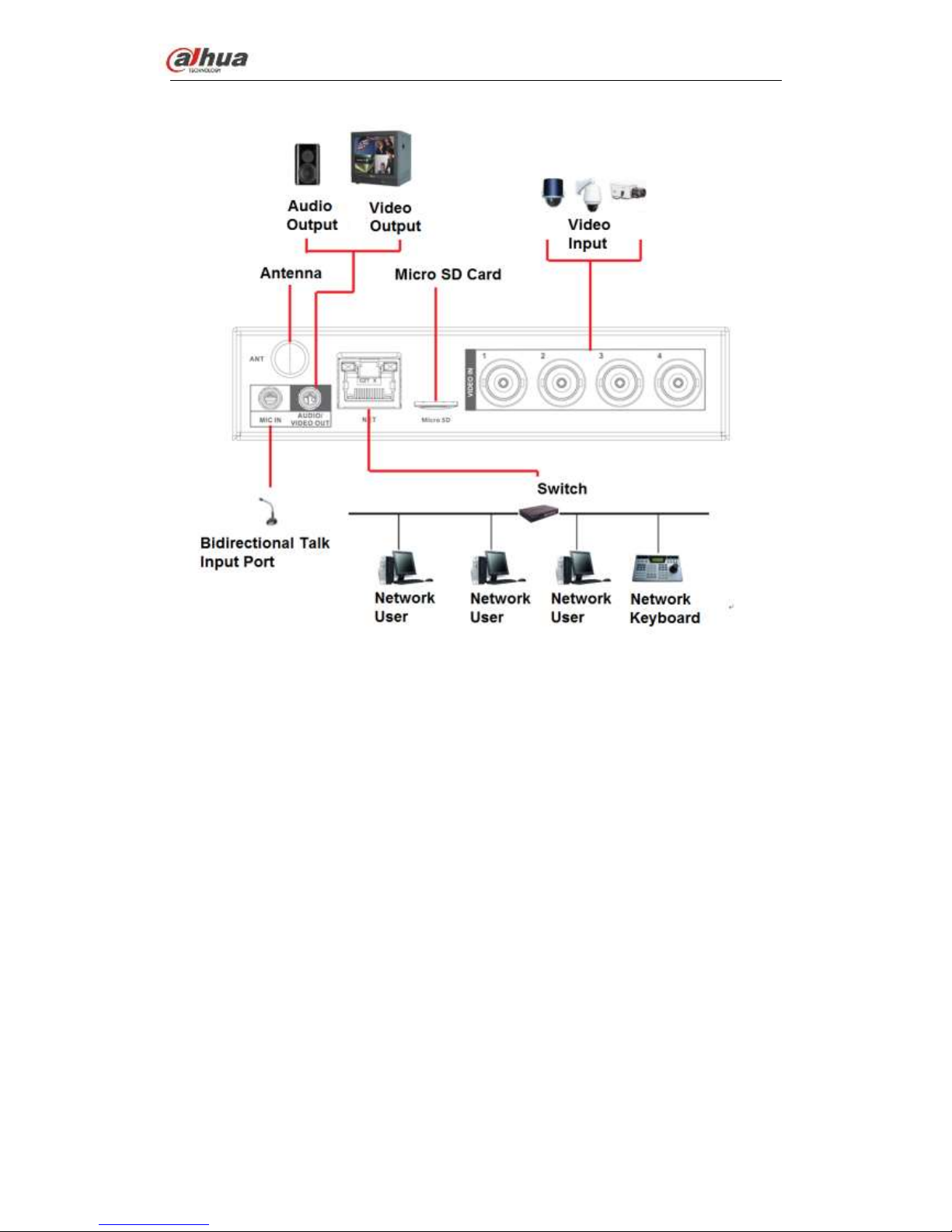
3.2 Connection Sample ................................................................................................................. 8
3.3 Connecting Power Supply ...................................................................................................... 9
3.4 Connecting Video Input and Output Devices ...................................................................... 9
3.4.1 Connecting Video Input...................................................................................................... 9
3.4.2 Connecting Video Output ................................................................................................ 10
3.5 Connecting Audio Input & Output, Bidirectional Audio .................................................... 10
3.5.1 Audio Input ......................................................................................................................... 10
3.5.2 Audio Output ...................................................................................................................... 10

Dahua Network Video Server User’s Manual
ii
3.6 Alarm Input and Output Connection ................................................................................... 10
3.6.1 Alarm Input and Output Details ...................................................................................... 11
3.6.2 Alarm Input Port ................................................................................................................ 11
3.6.3 Alarm Output Port ............................................................................................................. 12
3.7 RS485 ..................................................................................................................................... 13
4 WEB ....................................................................................................... 14
4.1 Network Connection .............................................................................................................. 14
4.2 Login and Logout ................................................................................................................... 15
4.3 Preview ................................................................................................................................... 17
4.3.1 LAN Mode .......................................................................................................................... 17
4.3.2 System Menu..................................................................................................................... 18
4.3.3 Start dialogue .................................................................................................................... 19
4.3.4 Instant record .................................................................................................................... 20
4.3.5 Local play ........................................................................................................................... 20
4.4 Setup ....................................................................................................................................... 23
4.4.1 Camera ............................................................................................................................... 23
4.4.2 Network .............................................................................................................................. 33
4.4.3 Event ................................................................................................................................... 57
4.4.4 Storage ............................................................................................................................... 77
4.4.5 Setup .................................................................................................................................. 82
4.5 Playback ................................................................................................................................. 96
4.5.1 Search Record .................................................................................................................. 97
4.5.2 Mark Playback ................................................................................................................... 99
4.5.3 File List ............................................................................................................................. 101
4.5.4 Playback ........................................................................................................................... 101
4.5.5 Download ......................................................................................................................... 102
4.5.6 Load more ........................................................................................................................ 102
4.6 Alarm ..................................................................................................................................... 105

Dahua Network Video Server User’s Manual
iii
4.7 Information ............................................................................................................................ 106
4.7.1 Version ............................................................................................................................. 106
4.7.2 Log .................................................................................................................................... 106
4.7.3 Online User ...................................................................................................................... 107
4.8 Log out .................................................................................................................................. 108
4.9 Un-install Web Control ........................................................................................................ 108
5 SMARTPSS .......................................................................................... 109
6 FAQ ...................................................................................................... 110

Dahua Network Video Server User’s Manual
iv
Welcome
Thank you for purchasing our NVS!
This user’s manual is designed to be a reference tool for the installation and operation of
your system.
Here you can find information about this series standalone NVS features and functions.
Before installation and operation please read the following safeguards and warnings
carefully!

Dahua Network Video Server User’s Manual
v
Important Safeguards and Warnings
1.Electrical safety
All installation and operation here should conform to your local electrical safety codes.
The product must be grounded to reduce the risk of electric shock.
We assume no liability or responsibility for all the fires or electrical shock caused by
improper handling or installation.
2.Transportation security
Heavy stress, violent vibration or water splash are not allowed during transportation,
storage and installation.
3.Installation
Keep upwards. Handle with care.
Do not apply power to the NVS before completing installation.
Do not place objects on the NVS.
4.Qualified engineers needed
All the examination and repair work should be done by the qualified service engineers.
We are not liable for any problems caused by unauthorized modifications or attempted
repair.
5.Environment
The NVS should be installed in a cool, dry place away from direct sunlight, inflammable,
explosive substances and etc.
6. Accessories
Be sure to use all the accessories recommended by manufacturer.
Before installation, please open the package and check all the components are included.
Contact your local retailer ASAP if something is broken in your package.
7. Lithium battery
Improper battery use may result in fire, explosion, or personal injury!
When replace the battery, please make sure you are using the same model!
RISK OF EXPLOSION IF BATTERY IS REPLACED BY AN INCORRECT TYPE.
DISPOSE OF USED BATTERIES ACCORDING TO THE INSTRUCTIONS.
CAUTION
FOR YOUR OWN SAFETY, PLEASE CHANGE SYSTEM DEFAULT PASSWORD
AFTER YOU FIRST LOGIN!

Dahua Network Video Server User’s Manual
1
1 FEATURES AND SPECIFICATIONS
1.1 Overview
This series product is an excellent digital surveillance product designed for security field.
It adopts embedded Linux OS to maintain reliable operation. It is easy to use and can
realize surveillance function after some simple settings. It has various functions such as
record, playback, monitor at the same time and can guarantee audio video
synchronization. This series product has advanced technology and strong network data
transmission function.
This series device adopts embedded design to achieve high security and reliability. It can
work in the local end, and at the same time, when connecting it to the professional
surveillance software (PSS), it can connect to the security network to realize strong
network and remote monitor function. It can upgrade current existing system to the HD
system without replacing original cables.
This series product can be widely used in various areas such as banking,
telecommunication, electric power, interrogation, transportation, intelligent resident zone,
factory, warehouse, resources, and water conservancy.
1.2 Features
Default
Just click one button to restore default setup.
A/D switch
Support analog/digital channel switch.
Various video types
WEB supports various signal sources: HDCVI signal/standard definition signal/high
definition/digital signal.
EQ
Image equalization and image equalization lock function.
Encode mode
SmartH264 encode.
Resistance heating
Support resistance heating function.
Real-time surveillance
Dahua Network Video Server User’s Manual
2
VGA port. Realize the surveillance through displayer/monitor.
Storage function
Special data format to guarantee data security and can remove the risk of the vicious data
modification.
MicroSD card storage. Hot swap. Auto resumes transmission after network connection
failure.
Compression format
Support multiple-channel audio and video. An independent hardware decodes the audio
and video signal from each channel to maintain video and audio synchronization.
Record & playback function
Support each channel real-time record independently, and at the same time it can support
search, forward play, network monitor, record search, download and etc.
Support various playback modes: slow play, fast play, backward play and frame by frame
play.
Support time title overlay so that you can view event accurate occurred time
Support digital zoom function during the preview.
Alarm activation function
Several relay alarm outputs to realize alarm activation and on-site light control.
The alarm input port and output has the protection circuit to guarantee device safety.
Communication port
Standard Ethernet port can realize network access function.
PTZ control
Support PTZ decoder via RS485.
Supoort various decode protocol to support PTZ and speed dome control function.
UPNP (Universal Plug and Play)
Establish mapping connection between LAN and WAN via UPNP protocol.
1.3 Specifications
Parameter
NVS0104HDC
NVS0204HDC
NVS0404HDC
System
Main
Processor
High-performance industrial embedded micro controller
OS
Embedded LINUX
System
Resources
Multiplex operations: Multiple-channel record, multiple-channel playback
and network operation simultaneously
Interface
No local interface. User-friendly WEB user interface

Dahua Network Video Server User’s Manual
3
Video monitor
Video Input
1-ch PAL/NTSC BNC;
(HDCVI HD
video/general standard
definition video
self-adaptive)
2-ch PAL/NTSC BNC;
(HDCVI HD
video/general standard
definition video
self-adaptive)
4-ch PAL/NTSC BNC;
(HDCVI HD
video/general standard
definition video
self-adaptive)
Video
Output
1-ch TV output. Reuse the Audio out port (Using 3.5mm AV cable to
output).
Loop Output
N/A
Matrix
Output
N/A
Record
Speed
Real-time Mode: PAL 1f/s to 25f/s per channel and NTSC 1f/s to 30f/s per
channel
Video Bit
Streams
32Kbps~4096Kbps
(720P: Default 2Mbps,max 4Mbps;1080P: Default 4M,max 4M)
Video
Partition
1 window
2 windows
4 windows
Monitor
Touring
N/A
Audio
Audio Input
1-ch
2-ch
4-ch
Audio
Output
1-ch bidirectional talk output. 3.5mm. Reuse the 3.5mm AV cable to output
audio.
Audio
Compressio
n Standard
G.711A, G.711U, PCM
Bidirectional
Talk
Reuse the audio output port
Audio
Sampling
Rate
8KHz, bidirectional talk(48KHz)
Audio Bit
Rate
64Kbps, bidirectional talk (384Kbps)
Video
Video
Compressio
n Standard
H.264. Support smartpH.264
Resolution
All-channel
1080P@25/30fps
All-channel
1080P@25/30fps
All-channel
720P@25/30fps;
1-channel 1080P
@25/30fps+3-channel
1080N realtime/
1080P/720P/960H/D1
@12/15fp
Alarm
Alarm Input
4-ch input

Dahua Network Video Server User’s Manual
4
Alarm
Output
2-ch output
Alarm
Pre-record
0 to 30 seconds pre-record when an alarm occurred.
Storage
HDD
Amount
1 Micro SD card
Storage
Manageme
nt
N/A
Port
SD Card
1 Micro SD card. Max 128G.
USB Port
N/A
Network
Port
1 RJ45 100/100Mbps self-adaptive Ethernet port
eSATA Port
N/A
RS485 Port
1 PTZ control port. Support various protocols.
RS232 Port
1 RS232 port
WIFI
(Optional)
Support 2.4G/5G module.
Indicator
Light
ACT/NET/ALM/VIDEO. Display status.
Antenna
Port
One antenna port. Connect to wireless module antenna.
General
Parameter
Power
Supplying
DC +12V/2A
Power
Consumptio
n
<10W
Working
Temperatur
e
-10℃~+55℃
Working
Humidity
10%~90%
Air Pressure
86kPa~106kPa
Dimension
137mm×162mm×30mm
Weight
1.0Kg
Installation
Mode
Desktop installation
Dahua Network Video Server User’s Manual
5
2 Overview and Controls
Note:
All the installation and operations here should conform to your local electric
safety rules.
2.1 Front Panel
The front panel is shown as below. See Figure 2-1.
Figure 2-1
Please refer to the following sheet for detailed information.
SN
Icon
Name
Function
1
ACT
Status indicator light
Connect the device to the power
source: The light is green. It is not so
bright.
Device is working properly: The light is
green. The light is bright.
Device is upgrading: The light is
flashing.
Device has shut down or there is no
power: The light is off.
2
VIDEO
Video indicator light
Connect to the analog video but device
is not recording: The light is on.
No analog video connected but device
is not recording: The light is off.
The device is recording: The light is
flashing.
3
1~4
Audio input port 1~4
Connect to audio input device such as
micrphone.
G
GND
Audio input ground.
A1~A4
Alarm input 1~4
They are to receive the signal from the
external alarm source. There are two

Dahua Network Video Server User’s Manual
6
SN
Icon
Name
Function
types; NO (normal open)/NC (normal
close).
When your alarm input device is using
external power, please make sure the
device and the NVS have the same
ground.
G
GND
Alarm input ground.
4
NO1~NO2
Alarm output port 1~2
2 groups of alarm output ports. (Group
1:port NO1~C1,Group 2:port NO2~
C2).Output alarm signal to the alarm
device. Please make sure there is
power to the external alarm device.
NO:Normal open alarm output port.
C:Alarm output public end.
G
GND
Alarm output ground.
A、B
RS-485 communication
port
RS485_A port. It is the cable A. You
can connect to the control devices
such as speed dome PTZ.
RS485_B.It is the cable B. You can
connect to the control devices such as
speed dome PTZ.
RX、TX
RS-232 communication
port
General serial port debug.
G
GND
COM ground
5
DC 12V
Power input port
12V 2A power port. DC 8V-DC 16V.
6 GND
Ground
7
ALM
Alarm indicator light
Device local alarm has been armed:
The light is on.
Device local alarm has triggered: The
light is flashing.
Device local alarm has been
disarmed:The light is off.
8
NET
Network status
indicator light
Wire network connection is OK: The
light is off.
Wire network connection is abnormal:
The light is on.
9
RESET
Reset
Press for 5 seconds to restore default
setup.
2.2 Rear Panel
The rear panel is shown as below. See Figure 2-2.
Dahua Network Video Server User’s Manual
7
Figure 2-2
Please refer to the following sheet for front panel button information.
SN
Icon
Name
Function
1
ANT
Screw to connect to the
antenna
Connect to antenna
2
NET
Network port
10M/100Mbps Ethernet port.
3
1~4
Video input port 1~4
Conenct to analog camera to input video
signal.
4
MIC IN
Bidirectional talk input
port
Bidirectional talk input port. It is to receive
the analog audio signal from the devices
such as microphone, pickup.
5
AUDIO/VIDEO
OUT
Audio/video output port
Using the cable in the accessories bag to
output video/audio signal at the same time
Video output port: Connect to output
device such as TV to view the video.
Audio output port: Connect to audio
output device to listen to audio.
When bidirectional talk function is
enabled, the audio output port is
working as the bidirectional talk output
port.
6
Micro SD
SD slot
Inseert Micro SD card.
Dahua Network Video Server User’s Manual
8
3 Device Installation
Note:
All the installation and operations here should conform to your local electric
safety rules.
3.1 Check Unpacked Device
When you received the device from the shipping agency, please check whether there is
any visible damage. The protective materials used for the package of the device can
protect most accidental clashes during transportation. Then you can open the box to
check the accessories.
Please check the items in accordance with the list. Finally you can remove the protective
film of the device.
The label at the bottom of the box is very important. Usually we need you to present the
serial number when we provide the service after sales.
3.2 Connection Sample
The connection sample is shown as in Figure 3-1 and Figure 3-2.
Figure 3-1
Dahua Network Video Server User’s Manual
9
Figure 3-2
3.3 Connecting Power Supply
Please check input voltage and device power button match or not.
We recommend you use UPS to guarantee steady operation, NVS life span, and other
peripheral equipment operation such as cameras.
3.4 Connecting Video Input and Output Devices
3.4.1 Connecting Video Input
The video input interface is BNC. The input video format includes: PAL/NTSC BNC
(1.0V
P-P
, 75Ω.)
The video signal should comply with your national standards.
The input video signal shall have high SNR, low distortion; low interference, natural color
and suitable lightness.
Guarantee the stability and reliability of the camera signal:
The camera shall be installed in a cool, dry place away from direct sunlight, inflammable,
explosive substances and etc.
The camera and the NVS should have the same grounding to ensure the normal

Dahua Network Video Server User’s Manual
10
operation of the camera.
Guarantee stability and reliability of the transmission line
Please use high quality, sound shielded BNC. Please select suitable BNC model
according to the transmission distance.
If the distance is too long, you should use twisted pair cable, and you can add video
compensation devices or use optical fiber to ensure video quality.
You should keep the video signal away from the strong electromagnetic interference,
especially the high tension current.
Keep connection lugs in well contact
The signal line and shielded wire should be fixed firmly and in well connection. Avoid dry
joint, lap welding and oxidation.
3.4.2 Connecting Video Output
System supports TV output.
When you are using pc-type monitor to replace the monitor, please pay attention to the
following points:
To defer aging, do not allow the pc monitor to run for a long time.
Regular demagnetization will keep device maintain proper status.
Keep it away from strong electromagnetic interference devices.
Using TV as video output device is not a reliable substitution method. You also need to
reduce the working hour and control the interference from power supply and other
devices. The low quality TV may result in device damage.
3.5 Connecting Audio Input & Output, Bidirectional Audio
3.5.1 Audio Input
These series products audio input port adopt BNC port.
Due to high impedance of audio input, please use active sound pick-up.
Audio transmission is similar to video transmission. Try to avoid interference, dry joint,
loose contact and it shall be away from high tension current.
3.5.2 Audio Output
The audio output signal parameter is usually over 200mv 1KΩ (RCA). It can directly
connect to low impedance earphone, active sound box or amplifier-drive audio output
device.
If the sound box and the pick-up cannot be separated spatially, it is easy to arouse
squeaking. In this case you can adopt the following measures:
Use better sound pick-up with better directing property.
Reduce the volume of the sound box.
Using more sound-absorbing materials in decoration can reduce voice echo and
improve acoustics environment.
Adjust the layout to reduce happening of the squeaking.
3.6 Alarm Input and Output Connection
Dahua Network Video Server User’s Manual
11
Please read the followings before connecting.
1. Alarm input
a. Please make sure alarm input mode is grounding alarm input.
b. Grounding signal is needed for alarm input.
c. Alarm input needs the low level voltage signal.
d. Alarm input mode can be either NC (normal Open) or NO (Normal Close)
e. When you are connecting two NVSs or you are connecting one NVS and one other
device, please use a relay to separate them,
2. Alarm output
The alarm output port should not be connected to high power load directly (It shall be less
than 1A) to avoid high current which may result in relay damage. Please use the co
contactor to realize the connection between the alarm output port and the load.
3. How to connect PTZ decoder
a. Ensure the decoder has the same grounding with NVS; otherwise you may not
control the PTZ. Shielded twisted wire is recommended and the shielded layer is used
to connect to the grounding.
b. Avoid high voltage. Ensure proper wiring and some thunder protection measures.
c. For too long signal wires, 120Ω should be parallel connected between A, B lines on
the far end to reduce reflection and guarantee the signal quality.
d. “485 A, B” of NVS cannot parallel connect with “485 port” of other device.
e. The voltage between of A, B lines of the decoder should be less than 5V.
4. Please make sure the front-end device has soundly earthed.
Improper grounding may result in chip damage.
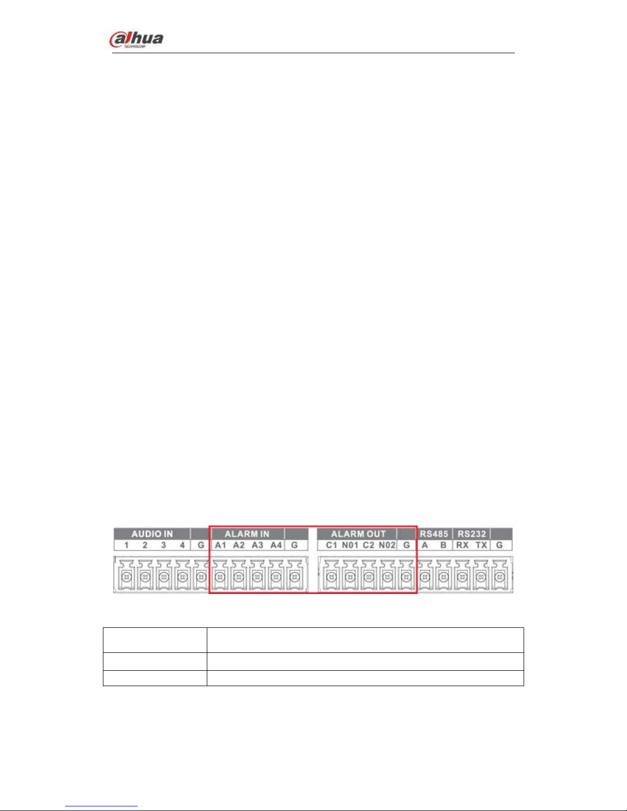
3.6.1 Alarm Input and Output Details
Figure 3-3
A1-A4
ALARM 1 to ALARM 4. The alarm becomes active in low voltage.
1-NO C, 2-NO C
There are two groups of normal open activation output (on/off button)
G
Ground cable.
3.6.2 Alarm Input Port
Please refer to the following sheet for more information.

Dahua Network Video Server User’s Manual
12
Grounding alarm inputs. Normal open or Normal close type)
Please parallel connect COM end and GND end of the alarm detector (Provide
external power to the alarm detector).
Please parallel connect the Ground of the NVS and the ground of the alarm detector.
Please connect the NC port of the alarm sensor to the NVS alarm input(ALARM)
Use the same ground with that of NVS if you use external power to the alarm device.
Figure 3-4
3.6.3 Alarm Output Port
Provide external power to external alarm device.
To avoid overloading, please read the following relay parameters sheet carefully.
RS485 A/B cable is for the A/B cable of the PTZ decoder.
T+,T-,R+,R- are four-wire double duplex RS485 port.
T+ T-: output wire
R+ R-: input wire
Relay Specification
Model:
JRC-27F
Material of the
touch
Silver
Rating
(Resistance
Load)
Rated switch capacity
30V DC 1A, 125V AC 0.5A
Maximum switch power
62.5VA /30W
Maximum switch voltage
125V AC,60V DC
Maximum switch currency
2A
Insulation
Between touch and loop
1000V AC 1minute
Length of open
time
3ms max ≤5ms
Length of close
time
3ms max ≤5ms
Longevity
Mechanical
次(300 times/MIN)
Electrical
次(30 times/MIN)

Dahua Network Video Server User’s Manual
13
Temperature
-30℃ ~+70℃
3.7 RS485
When the NVS receives a camera control command, it transmits that command up the coaxial
cable to the PTZ device. RS485 is a single-direction protocol; the PTZ device can’t return any
data to the unit. To enable the operation, connect the PTZ device to the RS485 (A,B) input on
the NVS.
Since RS485 is disabled by default for each camera, you must enable the PTZ settings first.
This series NVSs support multiple protocols such as Pelco-D, Pelco-P.
To connect PTZ devices to the NVS:
1. Connect RS485 A,B on the NVS rear panel.
2. Connect the other end of the cable to the proper pins in the connector on the camera.
3. Please follow the instructions to configure a camera to enable each PTZ device on the
NVS.
Dahua Network Video Server User’s Manual
14
4 WEB
4.1 Network Connection
1) Use network cable to connect PC with the NVS directly.
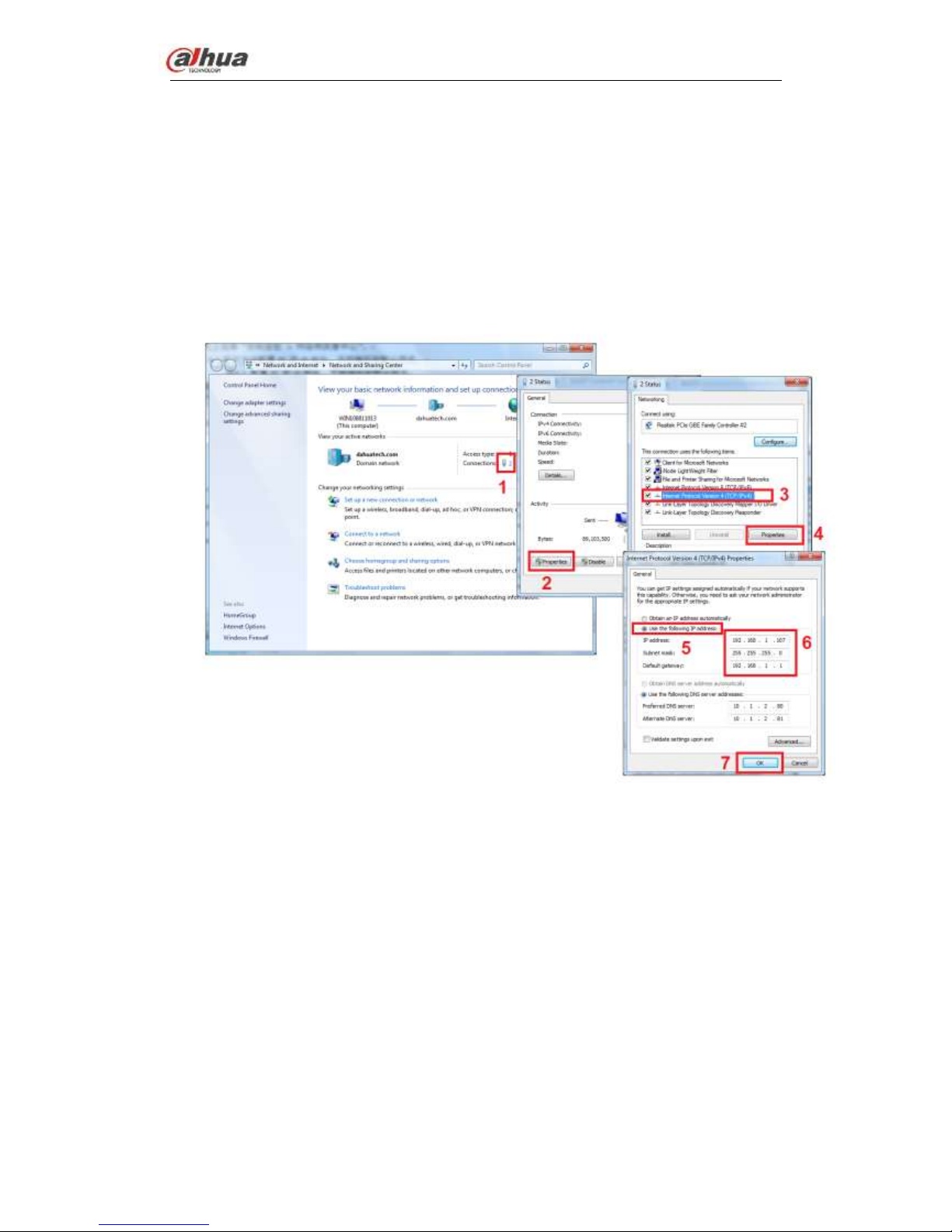
2) Change PC IP in the same IP segment with the NVS (192.168.1.108).For Windows
OS, from Control panel->Network and Internet->View network status and
task->Local connection->Properties->Internet protocol version
4(TCP/IP)->Properties, set PC IP address, subnet mask, default gateway and etc.
See Figure 4-1.
Figure 4-1
3) Open browser, input NVS default IP address 192.168.1.108.
4) Form Setup->Network-<TCP/IP, set NVS IP address. If there is a router in the
network, please set the corresponding gateway and subnet mask.
5) Connect NVS to the network.
6) Set PC IP address, subnet mask, gateway (if there is no router, please set the IP
address of the same IP segment. If there is a router, please set corresponding
gateway and subnet mask.)
7) Use command ping ***.***.***.***(NVS IP address) to check network. If the returned
TTL value is 255, the connection is OK now.
8) Open browser, input the NVS IP address.
Note
Dahua Network Video Server User’s Manual
15
WEB control can be downloaded and installed automatically. System can download
the latest Web control and remove the old one.
Run uninstall.bat (a tool to uninstall controls) to delete or go to the C:\Program
Files\webrec to delete WEB3.0 folder.
Current series product supports various browsers such as Safari, fire fox browser,
Google browser. Device supports multiple-channel monitor, PTZ control, NVS
parameter setup on the Apple PC.
4.2 Login and Logout
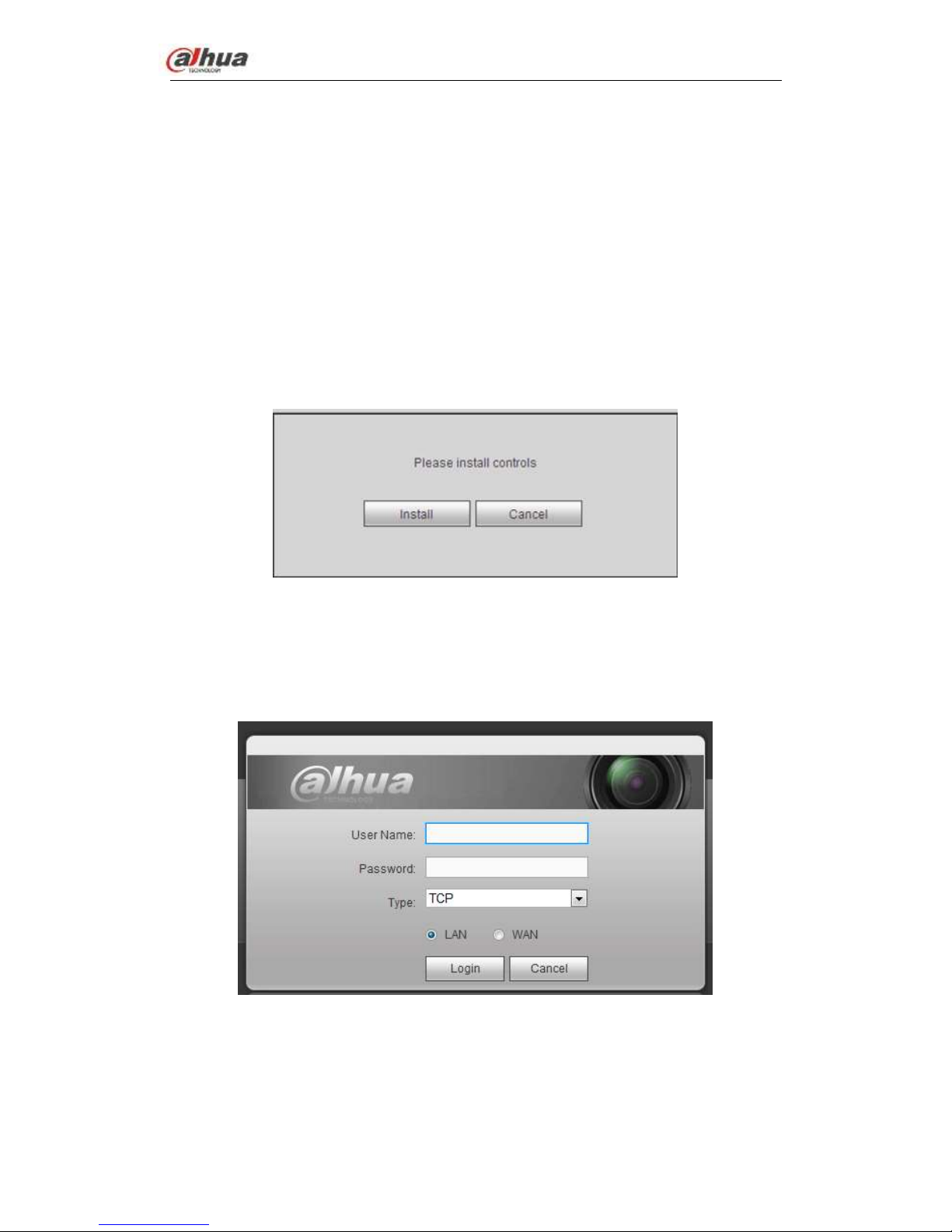
Open IE and input NVS address in the address column. For example, if your NVS IP is
10.10.3.16, then please input http:// 10.10.3.16 in IE address column.
System pops up warning information to ask you whether install control or not. Please click
Install button. See Figure 4-2.
Figure 4-2
After installation, the interface is shown as below. See Figure 4-3.
System default user name is admin and the password is admin.
If you can’t download the controls, please lower your browser security level or make sure
there is no other plug-in forbidding the download operation.
Figure 4-3
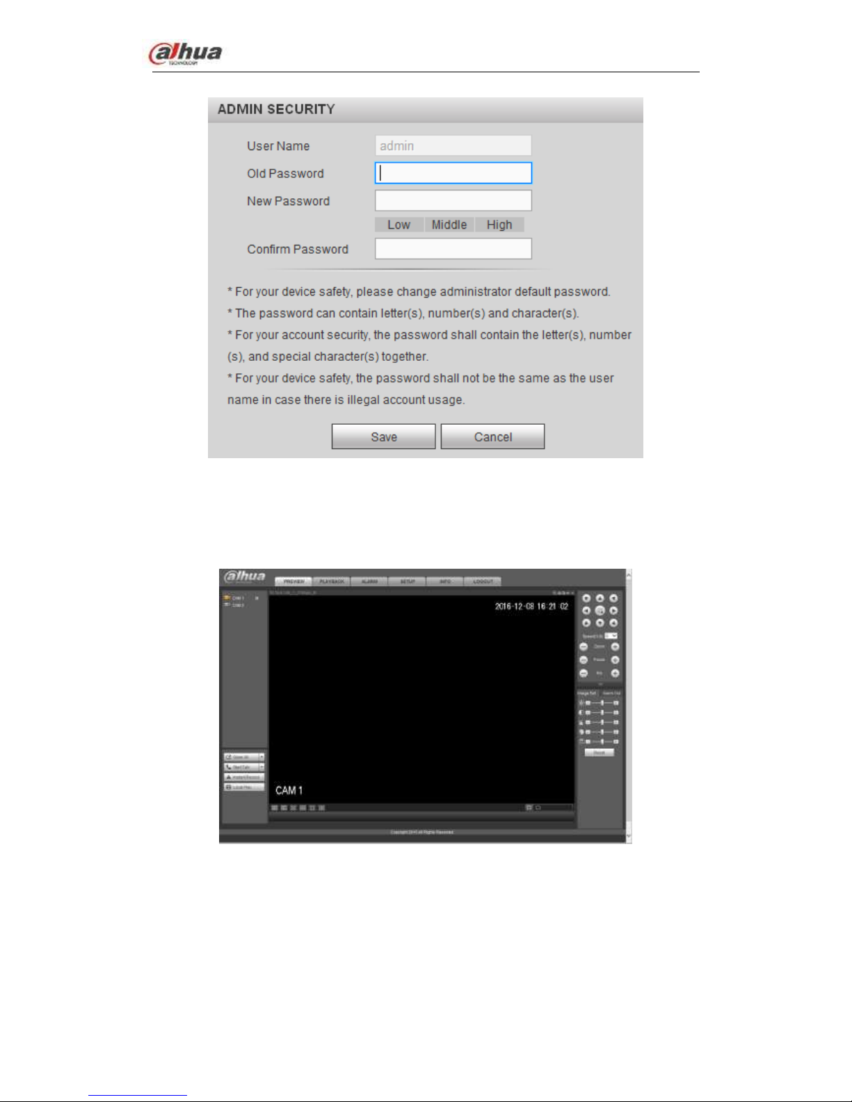
System pops up the following dialogue box for you to change administrator password. See
Figure 4-4.
For you own safety, please change the default password after you first login.
Dahua Network Video Server User’s Manual
16
Figure 4-4
Please input twice to set a password and then click Save button to complete the setup.
For the LAN mode, the interface is shown as in Figure 4-5.
Figure 4-5
For the WAN mode, the interface is shown as in Figure 4-6.
Dahua Network Video Server User’s Manual
17
Figure 4-6
4.3 Preview
4.3.1 LAN Mode
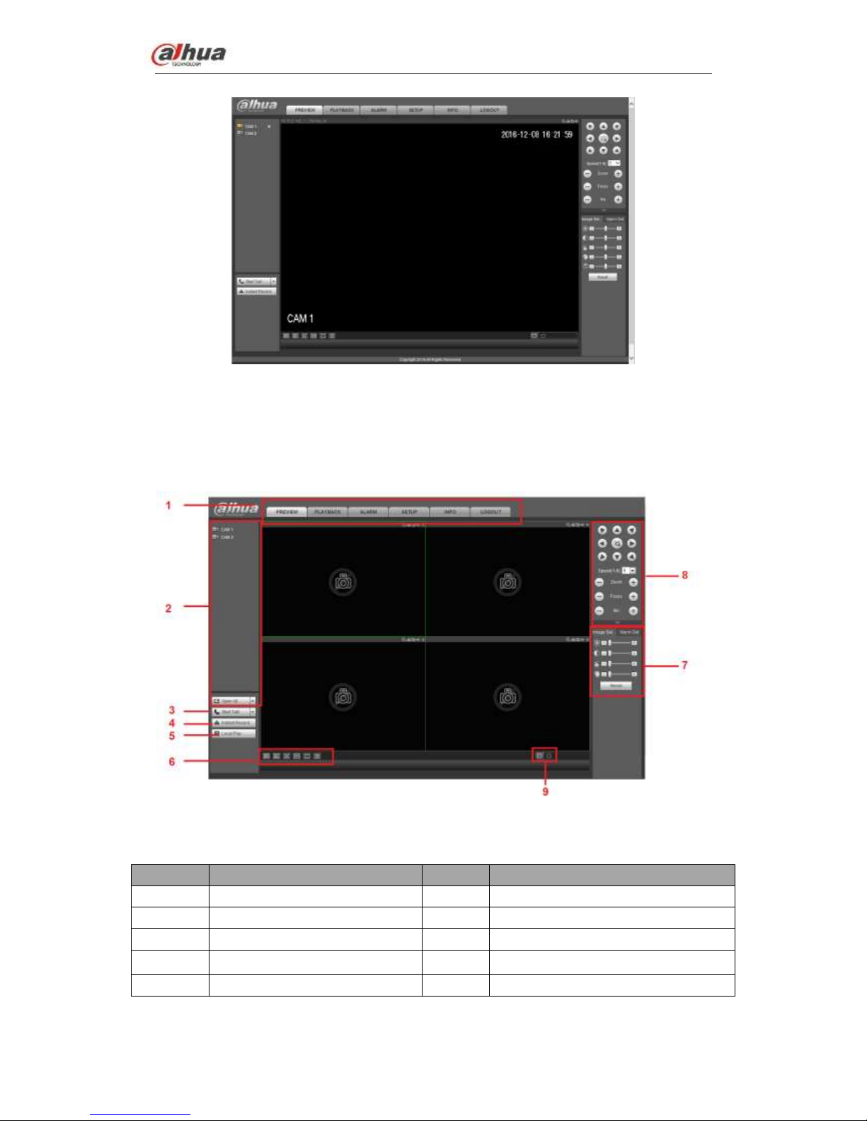
For the LAN mode, after you logged in, you can see the main window. See Figure 4-7.
Figure 4-7
Please refer to the following sheet for detailed information.
SN
Name
SN
Name
1
System menu
2
Realtime monitor channel
3
Bidirectional talk
4
Instant record
5
Local playback
6
Switch monitor window
7
Image setup /alarm output
8
PTZ control
9
Zero-channel encode
About LAN login and WAN login
Dahua Network Video Server User’s Manual
18
After WAN login, system opens the main stream video of the first channel by default.
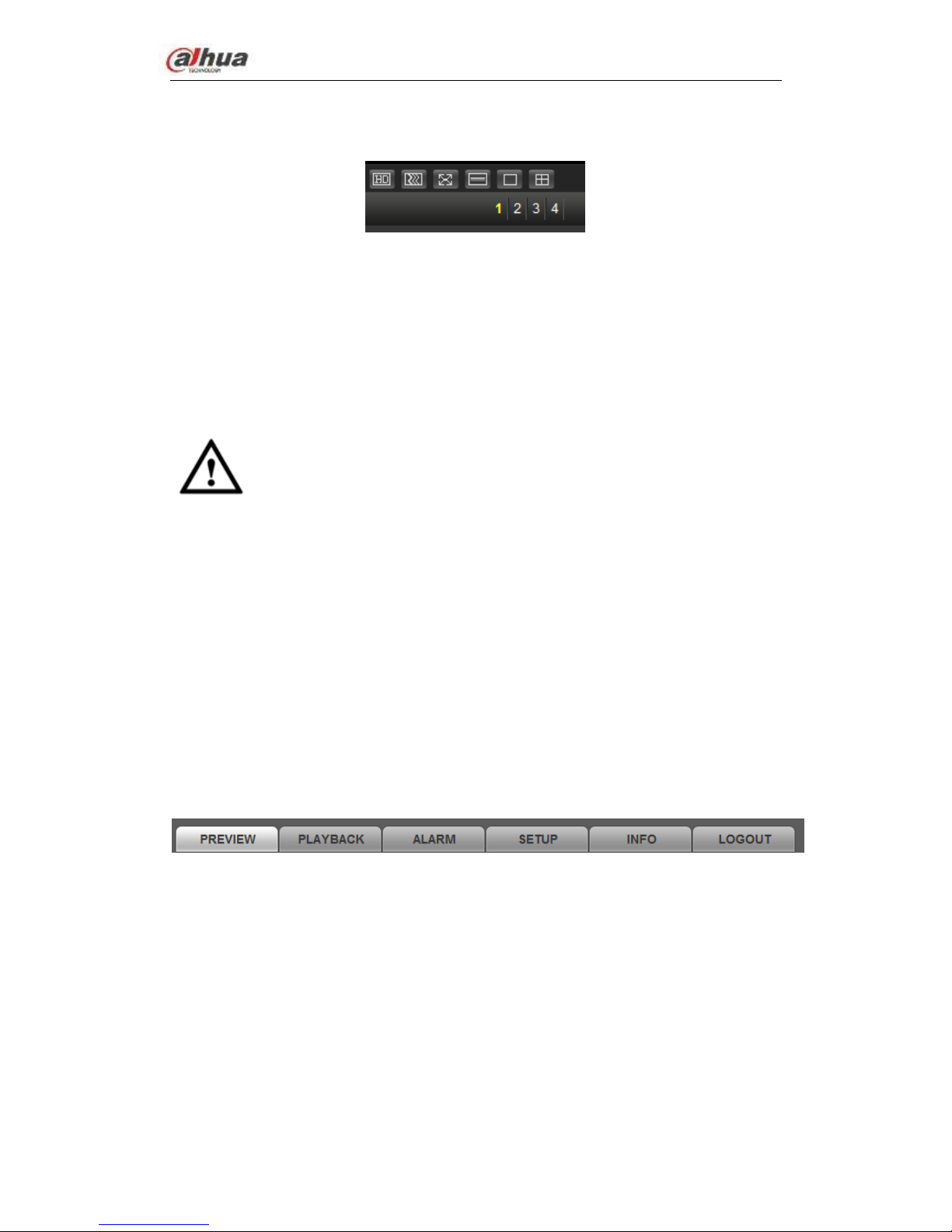
Refer to Figure 4-8 to select split mode and channel number.
Figure 4-8
The split amount depends on the channel number. For 4-channel series product, the max
split amount is 4.
In multiple-channel surveillance mode, system uses sub streams by default. Once you
double click a channel to go to one-channel surveillance mode, then system restores main
stream surveillance. Refer to the top left corner for main stream (M)/sub stream (S)
information.
Important
Please refer to the following contents for LAN and WAN login difference.
Important
For multiple-channel monitor mode, system adopts extra stream to monitor by default.
You can not modify manually. All channels are trying to synchronize. Please note the
synchronization effect still depends on your network environments.
For bandwidth consideration, system can not support monitor and playback at the
same time. System auto closes monitor or playback interface when you are searching
setup in the configuration interface. It is to enhance search speed.
4.3.2 System Menu
The system menu interface is shown as below. See Figure 4-123.
Please refer to chapter 4.3.2.1 Preview, chapter 4.4 Setup , chapter 4.5 Playback, chapter
4.6 Alarm, chapter 4.7 Info, chapter 4.8 Logout for detailed information.
Figure 4-9
4.3.2.1 Preview
Left click the channel name on the left pane of the main interface; you can see the
corresponding video in current window.
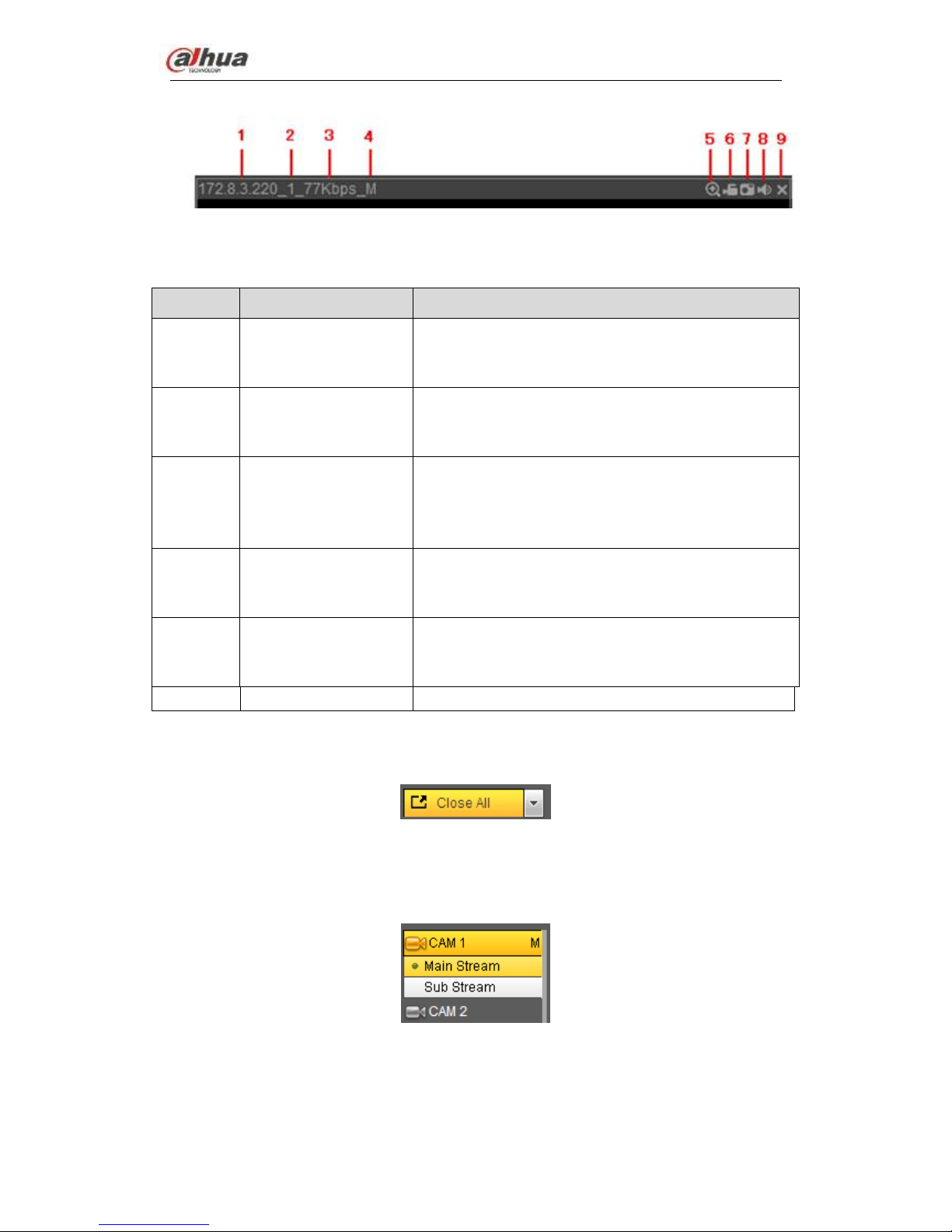
On the top left corner, you can view device IP, channel number, network monitor bit stream.
See Figure 4-10.
Dahua Network Video Server User’s Manual
19
Figure 4-10
Please refer to the following sheet for detailed information.
Name
Function
1-4
Display device
information
When there is video, it is to display “Device IP-Monitor
channel number-network bit stream-decode mode”.
Otherwise, it shows as “No video”.
5
Digital zoom
Click this button and then left drag the mouse in the
zone to zoom in. right click mouse system restores
original status.
6
Local record
When you click local record button, the system begins
recording and this button becomes highlighted. You
can go to system folder RecordDownload to view the
recorded file.
7
Snapshot
You can snapshoot important video. All images are
memorized in system client folder PictureDownload
(default).
8
Audio
Turn on or off audio.
Note:
It has no relationship with system audio setup.
9
Close video
Close video
4.3.2.2 Open All
Open all button is to enable/disable all-channel real-time monitor. Click it the button
becomes yellow. See Figure 4-11.
Figure 4-11
4.3.2.3 Main stream/sub stream
Please refer to Figure 4-12 for main stream and extra stream switch information.
Figure 4-12
4.3.3 Start dialogue
Dahua Network Video Server User’s Manual
20
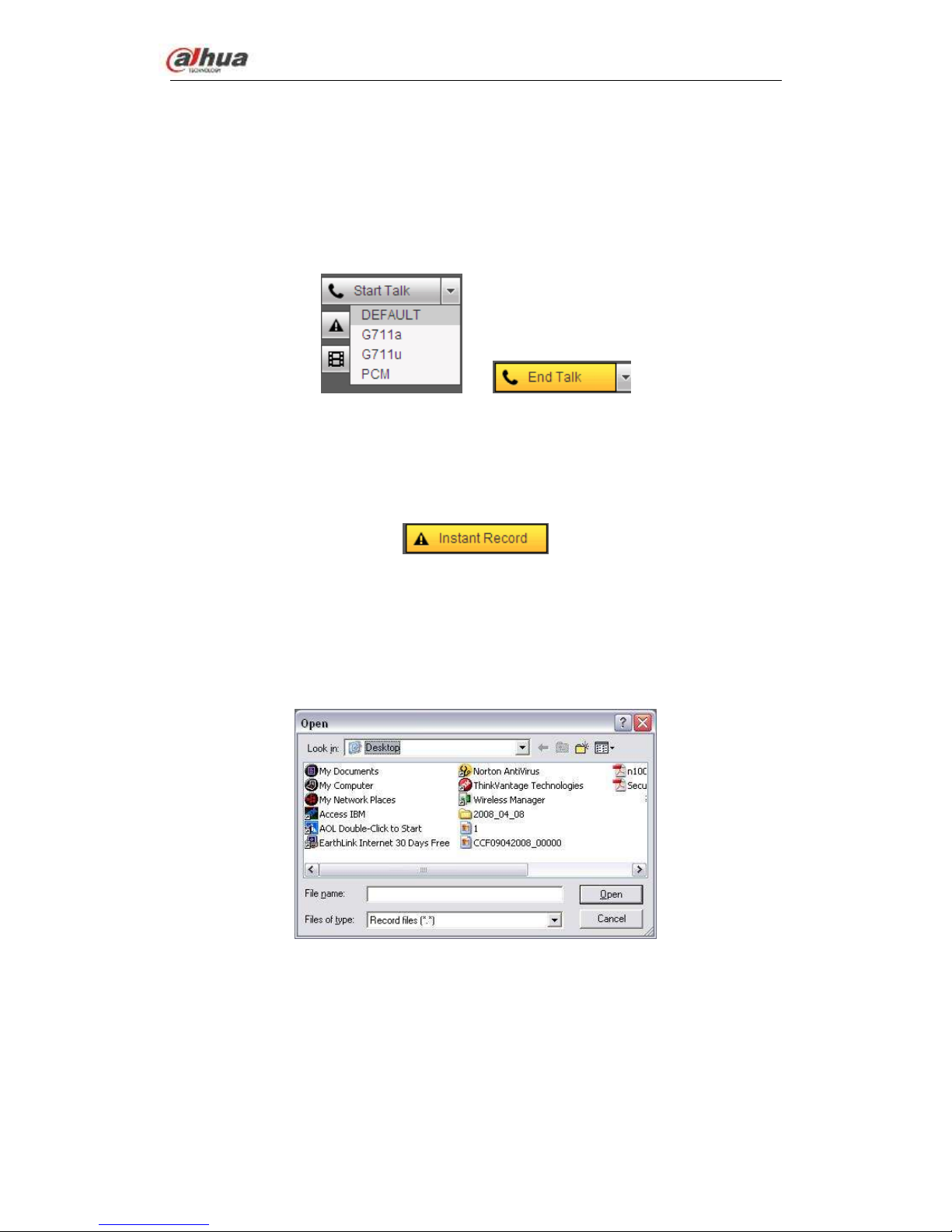
You can click this button to enable audio talk. Click 【▼】 to select bidirectional talk mode.
There are four options: DEFAULT,G711a,G711u and PCM. After you enable the
bidirectional talk, the Start talk button becomes End Talk button and it becomes yellow.
See Figure 4-13.
Please note, if audio input port from the device to the client-end is using the first channel
audio input port. During the bidirectional talk process, system will not encode the audio
data from the 1-channel.
Figure 4-13
4.3.4 Instant record
Click it, the button becomes yellow and system begins manual record. See Figure 4-14.
Click it again, system restores previous record mode.
Figure 4-14
4.3.5 Local play
The Web can playback the saved (Extension name is dav) files in the PC-end.
Click local play button, system pops up the following interface for you to select local play
file. See Figure 4-15.
Figure 4-15
4.3.5.1 Switch monitor window
You can set video fluency and real-time feature priority. See Figure 4-16.
Note
The following interface may vary due to different series product.
Dahua Network Video Server User’s Manual
21
Figure 4-16
SN
Name
Function
1
Image quality
Select high quality or low quality.
2
Fluency
For realtime preview, it can set video fluency or realtime
feature.
3
Full screen
Click to go to full screen. Click【Esc】to exit.
4
Synchronization
Enable this function when the decoded video is not fluent.
When enable this function, the video is slightly not fluent
but the whole video is complete.
When disable this function, the video may not be complete,
but it is fluent.
5
1-window
Display 1-window.
6
4-window
Display 4-window.
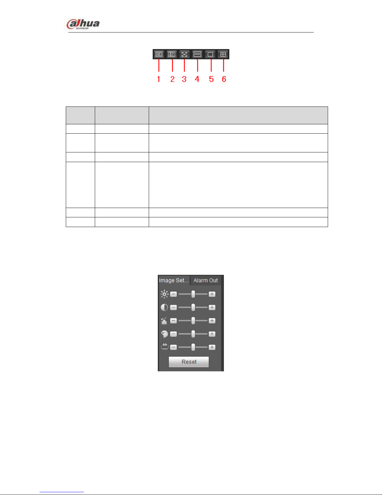
4.3.5.2 Image
Here you can adjust its brightness, contrast, hue and saturation. (Current channel border
becomes green). See Figure 4-17.
Or you can click Reset button to restore system default setup.
Figure 4-17
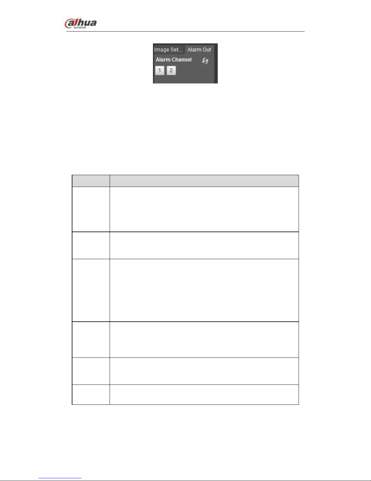
4.3.5.3 Alarm out
Here you can enable or disable the alarm signal of the corresponding port. See Figure
4-18.
Dahua Network Video Server User’s Manual
22
Figure 4-18
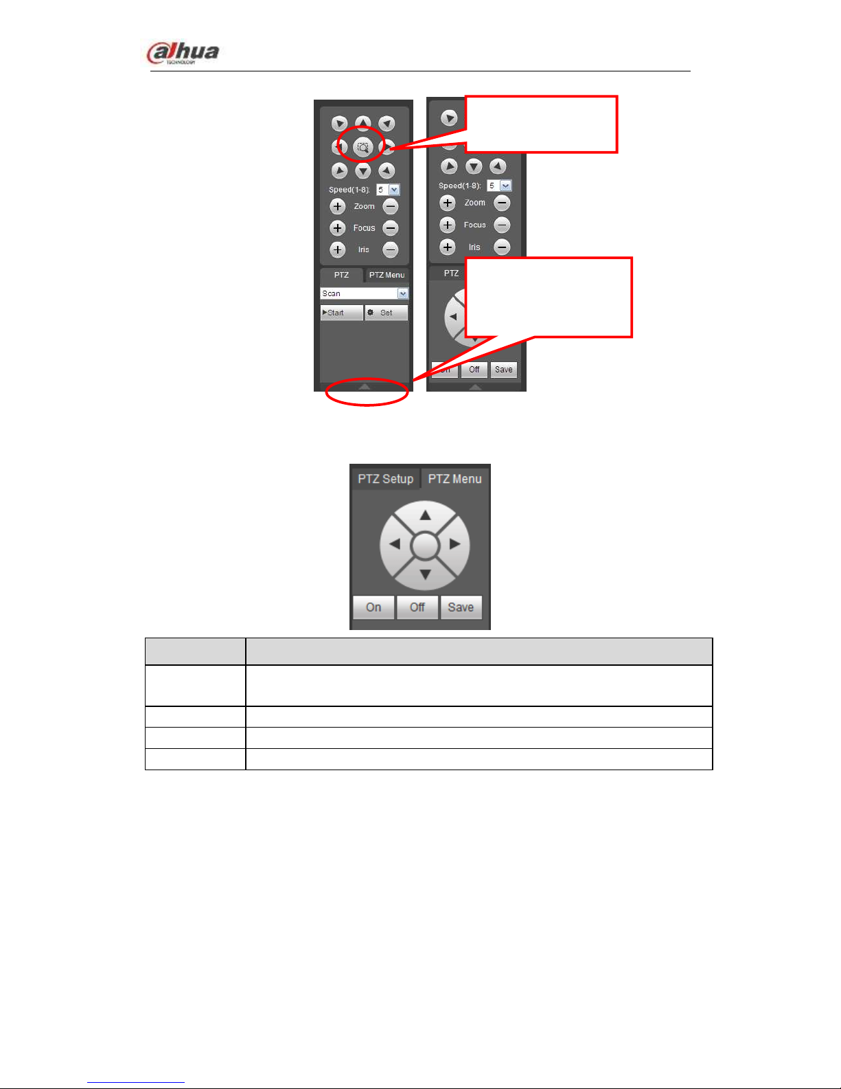
4.3.5.4 PTZ
Before PTZ operation, please make sure you have properly set PTZ protocol. (Please
refer to chapter 4.4.5.4).
There are eight direction keys. In the middle of the eight direction keys, there is a 3D
intelligent positioning key.
Click 3D intelligent positioning key, system goes back to the single screen mode. Drag the
mouse in the screen to adjust section size. It can realize PTZ automatically.
Please refer to the following sheet for PTZ setup information.
Parameter
Function
Scan
Select Scan from the dropdown list.
Click Set button, you can set scan left and right limit.
Use direction buttons to move the camera to you desired location
and then click left limit button. Then move the camera again and
then click right limit button to set a right limit.
Preset
Select Preset from the dropdown list.
Turn the camera to the corresponding position and Input the
preset value. Click Add button to add a preset.
Tour
Select Tour from the dropdown list.
Input preset value in the column. Click Add preset button, you
have added one preset in the tour.
Repeat the above procedures you can add more presets in one
tour.
Or you can click delete preset button to remove one preset from
the tour.
Pattern
Select Pattern from the dropdown list.
You can input pattern value and then click Start button to begin
PTZ movement such as zoom, focus, iris, direction and etc. Then
you can click Add button to set one pattern.
Aux
Please input the corresponding aux value here.
You can select one option and then click AUX on or AUX off
button.
Light and
wiper
You can turn on or turn off the light/wiper.
Dahua Network Video Server User’s Manual
23
Figure 4-19
PTZ Menu
Parameter
Function
Direction
buttons
Up/down button to select parameters, left/right button to select value.
Save
Confirm button.
On
Open OSD menu.
Off
Close OSD menu.
4.4 Setup
Here is to introduce NVS basic setups and system configurations.
4.4.1 Camera
It is to add network camera, set camera properties and set encode parameters.
4.4.1.1 Registration (For digital channel only)
Please go to main window->Setup->Camera->Channel type to enable IP channel function,
otherwise you can not see the following interface.
Here you can add network camera automatically or manually, set/delete corresponding
information and upgrade network camera.
You can click this icon to
display or hide the PTZ
control menu.
3D Intelligent Positioning
Key
Dahua Network Video Server User’s Manual
24
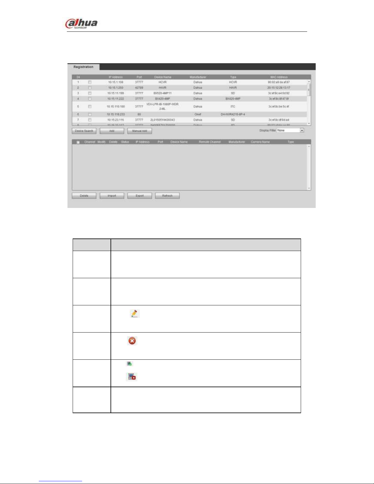
From main window->Setup->Camera->Registration, registration interface is shown as
below. See Figure 4-20.
Figure 4-20
Please refer to the following sheet for log parameter information.
Parameter
Function
Device
search
Click Device search button, you can view the searched device
information on the list. It includes device IP address, port, device
name, manufacturer and type.
Add
Select a device in the list and then click Add button, system can
connect the device automatically and add it to the Added device list.
Or you can double click one item in the list to add a device.
Modify
Click or any device in the Added device list, you can change the
corresponding channel setup.
Delete
Click , you can delete the remote connection of the corresponding
channel.
Connection
status
: Connection succeeded.
: Connection failed.
Delete
Select a device in the Added device list and then click Delete button,
system can disconnect the device and remove it from the Added
device list.
 Loading...