

Page 1

Network Video Server Quick Start Guide
V3.1.0
Page 2

i
Table of Contents
1 OVERVIEW .............................................................................................. 1
1.1 General Introduction .......................................................................................................... 1
1.2 Specifications ..................................................................................................................... 3
1.2.1 1-channel 4K High Definition Series ............................................................................ 3
1.2.2 4-channel 4K High Definition Series ............................................................................ 4
1.2.3 1/4-channel high Definition Series ................................................................ ................ 5
1.2.4 9/16-channel High Definition Series ............................................................................. 6
2 FRONT PANEL/REAR PANEL/INSTALLATION....................................... 9
2.1 Check Unpacked NVS ....................................................................................................... 9
2.2 Front panel .......................................................................................................................... 9
2.2.1 1/4-channel 4K High Definition &1/4-channel High Definition Series ........................ 9
2.2.2 9/16-channel High Definition Series ........................................................................... 10
2.3 Rear Panel ........................................................................................................................ 11
2.3.1 1-channel 4K High Definition Series .......................................................................... 11
2.3.2 4-channel 4K high definition series ............................................................................ 12
2.3.3 1-channel High Definition Series ................................................................................ 12
2.3.4 4-channel High Definition Series ................................................................................ 13
2.3.5 9-channel High Definition Series ................................................................................ 13
2.3.6 16-channel High Definition Series .............................................................................. 14
2.4 Connection ........................................................................................................................ 15
3 OPERATION........................................................................................... 16
3.1 Boot Up and Shut Down .................................................................................................. 16
Page 3

ii
3.2 Login.................................................................................................................................. 16
3.2.1 Preparation ................................................................................................................... 16
3.2.2 Login ................................................................................................ ............................. 17
3.3 Main Window .................................................................................................................... 18
3.4 Video Wall Splicing (Display Pane) Function ................................................................. 24
3.5 Add /Remove Front-end Device ...................................................................................... 27
3.5.1 Add device.................................................................................................................... 27
3.5.2 Delete Device ............................................................................................................... 27
3.6 Decode Channel Setup .................................................................................................... 27
3.7 File Playback and Time Playback ................................................................................... 28
3.7.1 File Playback ................................................................................................ ................ 29
3.7.2 Time Playback ............................................................................................................. 31
3.8 Decoder ............................................................................................................................ 31
3.8.1 Decode Tour ................................................................................................................ 31
3.8.2 Decode Output ................................................................................................ ............. 34
3.8.3 Decode Strategy .......................................................................................................... 34
3.8.4 Screen Show ................................................................................................................ 35
3.8.5 Output Options ................................ ............................................................................. 35
3.8.6 Background Color ........................................................................................................ 36
3.8.7 Split Line ................................................................................................ ....................... 36
4 ALARM INPUT AND OUTPUT ............................................................... 38
4.1 Alarm Input Port ............................................................................................................... 40
4.2 Alarm Output Port ............................................................................................................ 40
4.3 Alarm Output Relay Specifications ................................................................................. 41
Page 4

iii
Welcome
Thank you for purchasing our product!
This quick start guide will help you become familiar with our NVS in a very short time.
Before installation and operation please read the following safeguard and warning
carefully!
Please keep it well for future reference!
Page 5

iv
Important Safeguard and Warning
1.Electrical safety
All installation and operation here should conform to your local electrical safety codes.
The product must be grounded to reduce the risk of electric shock.
We assume no liability or responsibility for all the fires or electric shock caused by
improper handling or installation.
Please use three-pin power socket (with GND).
We are not liable for any problems caused by unauthorized modifications or attempted
repair.
2.Installation
Do not apply power to the NVS before completing installation.
Do not put object on the NVS.
3.Environment
This series NVS should be installed in a cool, dry place away from direct sunlight,
inflammable, explosive substances and etc.
Please guarantee sound ventilation and keep device clean.
4. About Accessories
Be sure to use all the accessories recommended by manufacturer.
Contact your local retailer ASAP if something is damaged in the accessory package.
Page 6

1
1 Overview
1.1 General Introduction
These high definition series product is a network audio & video decode device designed
and developed for the video network monitor system. It has elegant shape and strong
data process capability. It has stable and sound network function and supports all popular
encode modes. This series product has sound expansibility and it is easy to maintain and
connect.
This kind of design is convenient for the whole network video surveillance system to install,
control and manage. At the same time, it greatly reduces the system cost.
The decoder adopts embedded OS and effectively guarantees the security, stability,
reliability and high performance of the network video surveillance system.
These series products all support window split function.
Model
Decode Output Capability
Output Port
Split Mode
1-channel 4K
high definition
series
16-channel 1080P resolution
video decode output
12-channel 300w video decode
output.
7-channel 500w video decode
output.
6-channel 600w video decode
output.
4-channel 800w video decode
output.
1-channel 1200w video decode
output.
1-channel 1080P SVAC video
decode output.
1-channel 1080P H.265 video
decode output.
VGA
HDMI
The TV screen supports
1/4/9/16-window display
mode.
4-channel 4K
high definition
series
4-channel 1200W video decode
output.
4--channel 800W video decode
output.
16-channel 1080P video decode
VGA
HDMI
BNC
The TV screen supports
1/4/9/16-window display
mode.
Page 7

2
Model
Decode Output Capability
Output Port
Split Mode
output.
36-channel 720P video decode
output.
64-channel 960H video decode
output.
4-channel 1200W H.265 video
decode output.
4-channel 800W H.265 video
decode output.
16-channel 1080P H.265 video
decode output.
36-channel 720P H.265 video
decode output.
64-channel 960H H.265 video
decode output.
1-channel
high definition
series
4-channel 1080P resolution
video decode output.
12-channel 960H resolution
video decode output
16-channel D1 resolution video
decode output
VGA
HDMI
BNC
The TV screen supports
1/4/9/16-window display
mode.
4-channel
high definition
series
7-channel 1080P resolution
video decode output.
24-channel 960H resolution
video decode output
28-channel D1 resolution video
decode output
VGA
HDMI
BNC
The first TV screen
supports
1/4/9/16-window display
mode. The rest TV
screens support
1/4-window display
mode.
9-channel
high definition
series
2-channel 800w resolution
non-real time video decode
output.
8-channel 500w resolution
non-real time video decode
output.
8-channel 300w resolution
non-real time video decode
output.
9-channel 1080P resolution
VGA
HDMI
The first TV screen
supports
1/4/9/16-window display
mode. The rest TV
screens support
1/4-window display
mode.
Page 8
3
Model
Decode Output Capability
Output Port
Split Mode
video decode output.
33-channel 720P resolution
video decode output.
44-channel 960H resolution
video decode output
48-channel D1 resolution video
decode output
16-channel
high definition
series
4-channel 800w resolution
non-real time video decode
output.
16-channel 500w resolution
non-real time video decode
output.
16-channel 300w resolution
non-real time video decode
output.
26-channel 1080P 8 Mbps or
32-channel 1080P 6Mbps
resolution video decode output.
52-channel 720P resolution
video decode output.
64-channel 960H resolution
video decode output
64-channel D1 resolution video
decode output
VGA
HDMI
The TV screen supports
1/4-window display
mode.
1.2 Specifications
1.2.1 1-channel 4K High Definition Series
System
Parameter
Device Model
1-channel 4K high definition series
Main Processor
High performance industry embedded micro processor
OS
Embedded LINUX
Input Device
Front panel button and keyboard
Shortcut Menu
N/A
Hardware
Port
Video Standard
SVAC/MPEG4/H.264/MJPEG/H.265
Audio Standard
PCM/G711
Page 9

4
Specification
Decode
Display
Resolution
QCIF/CIF/2CIF/HD1/D1/960H/720P/1080P/300w/500w/600w/800w/
1200w
Video Frame
Rate
PAL:1~25f/s;NTSC:1~30f/s
Bit stream Type
Composite stream/Video stream
Video Output
Channel
1 channel
Video Output
Port
VGA/HDMI
Audio Output
Channel
1 channel
Audio Output
Port
HDMI
Communication
Port
One RJ45 10M/ 100M/1000M self-adaptive Ethernet port
One RS232 port
One RS485 ports (semi-duplex)
Audio Talk
Channel
1 channel
Audio Talk Port
RCA(Level: 2Vrms. Output resistance : 10kΩ)
Alarm input
4 channels
Alarm Output
4-ch relay output (30VDC 1A.125VAC 0/5A activation output)
Working
Environment
and Other
Physical
Specification
Power
DC12V, 3.3A
Power
Consumption
≤20W
Working
Temperature
-10℃~+55℃
Working
Humidity
10%-95% 86kpa-106kpa
Dimension
(mm)
440×300×42.1mm
Weight
3.00 kg—3.50 kg
1.2.2 4-channel 4K High Definition Series
System
Parameter
Device Model
4-channel 4K high definition series
Main Processor
High performance industry embedded micro processor
OS
Embedded LINUX
Input Device
Front panel button and keyboard
Shortcut Menu
N/A
Hardware
Port
Video Standard
MPEG4/H.264/MJPEG/H.265
Audio Standard
PCM/G711
Page 10

5
Specification
Decode
Display
Resolution
QCIF/CIF/2CIF/HD1/D1/960H/720P/1080P/300w/500w/600w/800w/
1200w
Video Frame
Rate
PAL:1~25f/s;NTSC:1~30f/s
Bit stream Type
Composite stream/Video stream
Audio/video
input Channel
1 channel
Audio/video
input Port
HDMI
Video Output
Channel
4 channels
Video Output
Port
VGA/HDMI/BNC
Audio Output
Channel
4 channels
Audio Output
Port
HDMI/BNC(Level: 0.2V~3V, Output resistance: 5kΩ)
Communication
Port
One RJ45 10M/ 100M/1000M self-adaptive Ethernet port
One RS232 port
One RS485 port
One RJ45 port for screen control
Audio Talk
Channel
1 channel
Audio Talk Port
BNC(Level: 2Vrms. Output resistance : 10kΩ)
Alarm input
4 channels
Alarm Output
4-ch relay output (30VDC 1A.125VAC 0/5A activation output)
Working
Environment
and Other
Physical
Specification
Power
DC12V, 5.0A
Power
Consumption
≤40W
Working
Temperature
-10℃~+55℃
Working
Humidity
10%-95% 86kpa-106kpa
Dimension
(mm)
440×300×42.1mm
Weight
3.00 kg—3.50 kg
1.2.3 1/4-channel high Definition Series
System
Parameter
Device Model
1-channel high definition series
4-channel high definition series
Main Processor
High performance industry embedded micro processor
OS
Embedded LINUX
Page 11
6
Input Device
Front panel button and keyboard
Shortcut Menu
N/A
Hardware
Port
Specification
Video Standard
MPEG4/H.264/ MJPEG
Audio Standard
PCM/G711
Decode
Display
Resolution
QCIF/CIF/2CIF/HD1/D1/960H/720P/1080P
Video Frame
Rate
PAL:1~25f/s;NTSC:1~30f/s
Bit stream Type
Composite stream/Video stream
Video Output
Channel
1 channels
4 channels
Video Output
Port
VGA/HDMI/BNC
Audio Output
Channel
1 channel
4 channels
Audio Output
Port
HDMI/BNC(Level: 200-3000 mV. Resistance: 5Ω)
Communication
Port
One RJ45 10M/ 100M/1000M self-adaptive Ethernet port
One RS232 port
Two duplex RS485 ports
Audio Talk
Channel
1 channel
Audio Talk Port
BNC(Level: 2Vrms. Output resistance : 10kΩ)
Alarm input
16 channels
Alarm Output
8-ch relay output (30VDC 1A.125VAC 0/5A activation output)
Working
Environment
and Other
Physical
Specification
Power
DC12V, 3.3A
DC12V, 5.0A
Power
Consumption
≤10W
≤40W
Working
Temperature
-10℃~+55℃
Working
Humidity
10%-95% 86kpa-106kpa
Dimension
(mm)
440×300×42.1mm
Weight
3.00 kg—3.50 kg
1.2.4 9/16-channel High Definition Series
System
Parameter
Device Model
9-channel high definition series
16-channel high definition
series
Main Processor
High performance industry embedded micro processor
Page 12

7
OS
Embedded LINUX
Input Device
Front panel button and keyboard
Shortcut Menu
N/A
Hardware
Port
Specification
Video Standard
MPEG4/H.264/ MJPEG
Audio Standard
PCM/G711
Decode
Display
Resolution
QCIF/CIF/2CIF/HD1/D1/960H/720P/1080P/300w/500w/600w/
800w
Video Frame
Rate
PAL:1~25f/s;NTSC:1~30f/s
Bit stream Type
Composite stream/Video stream
Video Output
Channel
9 channels
16 channels
Video Output
Port
VGA/HDMI
VGA/HDMI
Audio Output
Channel
9 channels
16 channels
Audio Output
Port
HDMI/DB15 audio BNC
HDMI/DVI-I audio BNC
Communication
Port
One RJ45 10M/ 100M/1000M
self-adaptive Ethernet port
One RS232 port
One standard RS485 port
Two RJ45 10M/
100M/1000M
self-adaptive Ethernet
ports
One RS232 port
One standard RS485
port
Audio Talk
Channel
1 channel
Audio Talk Port
3.5mm jack port, input port: 3.5mm port(Level 2V Line in/50mV
Mic in,input resistance10kΩ); output port:3.5mm port(Level 2V,
output resistance 16Ω)
Alarm input
4 channels
N/A
Alarm Output
4-ch relay output (30VDC
1A.125VAC 0.5A activation
output)
N/A
Working
Environment
and Other
Physical
Specification
Power
AC100-240V, 50Hz~60Hz
Power
Consumption
≤70W
≤90W
Working
Temperature
-10℃~+55℃
Working
Humidity
10%-95% 86kpa-106kpa
Page 13

8
Dimension
(mm)
440X408X70mm
448×440×89mm
Weight
4.5kg~4.8kg
7kg~7.5kg
Page 14
9
2 Front Panel/Rear Panel/Installation
Note:
All the installation and operations here should conform to your local electric
safety rules.
VGA cable quality and length can affect the video quality. It may result in
distorted video, noise, black margin. The video quality may vary even if you are
viewing the same video via different VGA cables.
2.1 Check Unpacked NVS
When you received the NVS from the shipping agency, please check whether there is any
visible damage. The protective materials used for the package of the NVS can protect
most accidental clashes during transportation. Then you can open the box to check the
accessories.
Please check the items in accordance with the list.
Finally you can remove the protective film of the NVS.
The label at the bottom of the box is very important. Usually we need you to present the
serial number when we provide the service after sales.
2.2 Front panel
2.2.1 1/4-channel 4K High Definition &1/4-channel High Definition Series
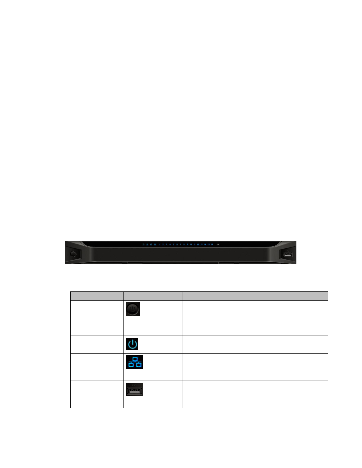
The 1-channel 4K high definition and 1/4-channel high definition series front panel is
shown as in Figure 2-1.
Figure 2-1
Please refer to the following sheet for detailed information.
Name
Icon
Function
Power button
Press it for three seconds to boot up or shut down the
device.
Press it three times within one second, it can clear
device configuration.
Power indicator
light
The indicator light becomes on when system boots up.
Network indicator
light
The indicator light becomes on when abnormal
network event occurs (offline, IP conflict and etc.)
USB port
Connect to external USB device.
Page 15
10
Name
Icon
Function
Alarm indicator
light
N/A
HDD indicator
light
N/A
IR receiver
N/A
Output indicator
light
It is to display output port working mode.
For 1-channel 4K high definition series and 1-channel
high definition series, only the first indicator light is
effective.
For 4-channel 4K high definition series and 4-channel
high definition series, only the channel 1 to channel 4
indicator lights is effective.
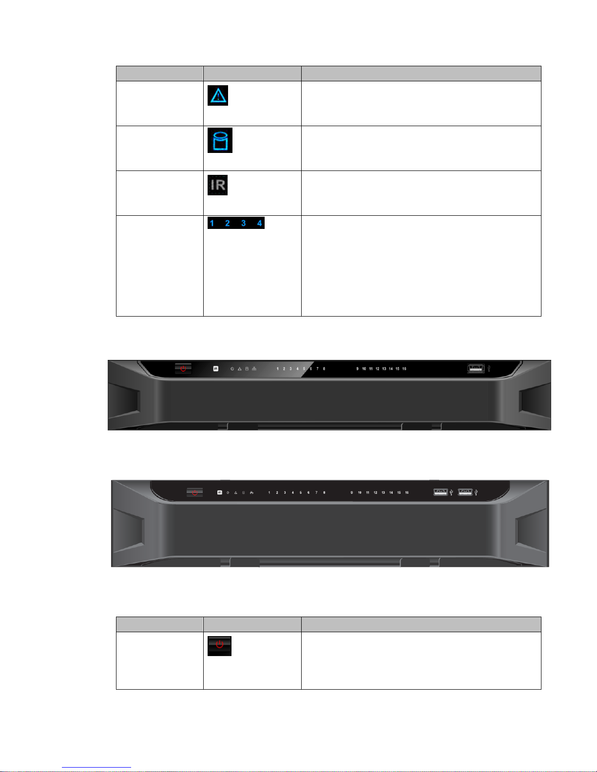
2.2.2 9/16-channel High Definition Series
The 9-channel high definition series front panel is shown as in Figure 2-2.
Figure 2-2
The 16-channel high definition series front panel is shown as in Figure 2-3.
Figure 2-3
Please refer to the following sheet for detailed information.
Name
Icon
Function
Power button
Press it for three seconds to boot up or shut down the
device.
Press it three times within one second, it can clear
device configuration.
Page 16

11
Name
Icon
Function
Power indicator
light
The indicator light becomes on when system boots up.
Network indicator
light
The indicator light becomes on when abnormal
network event occurs (offline, IP conflict and etc.)
USB port
Connect to external USB device.
Alarm indicator
light
N/A
HDD indicator
light
N/A
IR receiver
N/A
Output indicator
light
It is to display output port working mode.
For 9-channel high definition series, only the channel
1 to channel 9 indicator light is effective.
For 16-channel high definition series, only the channel
1 to channel 16 indicator light is effective.
2.3 Rear Panel
2.3.1 1-channel 4K High Definition Series
The rear panel is shown as below. See Figure 2-4.
Figure 2-4
Please refer to the following sheet for detailed information.
SN
Port Name
SN
Port Name
SN
Port Name
1
Ground screw
hole
2
RS232 port
3
USB port
4
HDMI port
5
Network
interface(10M/100M/1
000M self-adaptive
Ethernet port)
6
VGA port
Page 17

12
SN
Port Name
SN
Port Name
SN
Port Name
7
Audio talk output
port RCA OUT
8
Audio talk input
port RCA IN
9
4-channel alarm input,
4-channel alarm output,
RS485 port.
10
Power socket
11
Power switch
2.3.2 4-channel 4K high definition series
The rear panel is shown as below. See Figure 2-5.
Figure 2-5
Please refer to the following sheet for detailed information.
SN
Port Name
SN
Port Name
SN
Port Name
1
Ground screw hole
2
Audio output port(BNC)
3
Video output port
(BNC)
4
Audio talk input
port
5
Audio talk output
port
6
VGA port
7
HDMI output port
8
HDMI input port
9
RS232 port
10
RS232 port to control
the screen
11
Network
interface(10M/100M/1000
M self-adaptive Ethernet
port)
12
USB port
13
Alarm input, alarm
output, standard RS485
port
14
Power on-off button
15
Power socket
2.3.3 1-channel High Definition Series
The rear panel is shown as below. See Figure 2-6.
Figure 2-6
Please refer to the following sheet for detailed information.
Page 18

13
SN
Port Name
SN
Port Name
SN
Port Name
1
Ground screw hole
2
Audio output port(BNC)
3
Video output port (BNC)
4
Audio talk input
port
5
Audio talk output
port
6
VGA port
7
RS232 port
8
HDMI port
9
Network
interface(10M/100M/100
0M self-adaptive
Ethernet port)
10
Relay input, relay
output, duplex RS485
port
11
Power socket
12
Power switch
2.3.4 4-channel High Definition Series
The rear panel is shown as in Figure 2-7.
Figure 2-7
Please refer to the following sheet for detailed information.
SN
Port Name
SN
Port Name
SN
Port Name
1
Ground screw hole
2
Audio output port(BNC)
3
Video output port (BNC)
4
Audio talk output
port
5
Audio talk input
port
6
VGA port
7
HDMI port
8
RS232 port
9
Network
interface(10M/100M/100
0M self-adaptive
Ethernet port)
10
Relay input, relay
output, duplex RS485
port
11
Power socket
12
Power switch
2.3.5 9-channel High Definition Series
The rear panel is shown as below. See Figure 2-8.
Page 19

14
Figure 2-8
Please refer to the following sheet for detailed information.
SN
Port Name
SN
Port Name
SN
Port Name
1
Ground screw hole
2
Power switch
3
Power socket
4
HDMI port
5
Network
interface(10M/100M/1000M
self-adaptive Ethernet port)
6
Relay input, relay
output, standard RS485
port.
7
Audio talk input
port
8
Audio talk output
port
9
Audio output port
10
RS232 port
11
VGA port
2.3.6 16-channel High Definition Series
The rear panel is shown as below. See Figure 2-9.
Figure 2-9
Please refer to the following sheet for detailed information.
SN
Port Name
SN
Port Name
SN
Port Name
1
Ground screw hole
2
Power switch
3
Power socket
4
HDMI port (16)
5
VGA port (16)
6
Audio talk output port
7
Audio output port
8
Standard RS485 port
9
Audio talk input port
10
Network
11
RS232 port
Page 20

15
interface(10M/100M/1000M
self-adaptive Ethernet port)
Note:
When you connect it to the PC network port, please use crossover cable.
When you connect it to the PC via router or switcher, please use straight cable.
2.4 Connection
Please refer to the follow figure for connection information. See Figure 2-10.
The following figure is based on the 4-channel high definition series product.
Figure 2-10
Page 21

16
3 Operation
The following operations are generally based on the 9-channel high definition
series product.
Slight different may be found in the user interface.
3.1 Boot Up and Shut Down
Boot up
Connect the NVS to the power and then press the power button in the rear panel. You can
see the power indicator light becomes on and NVS boots up.
The system is in multiple-window display mode by default.
Shut down
You can press power button in the front panel for three seconds to shut down the device.
System Restore after Power Failure
When decoder is working, if the power failure occurs, the system can automatically
connect to the front-end device and restore previous working status once the power
connection becomes normal.
3.2 Login
3.2.1 Preparation
Before log in, please make sure:
NVS connection is OK.
You have set PC IP address, NVS IP address, subnet mask and gateway. (Please set
the IP address of the same section for the PC and NVS. Please input corresponding
gateway and subnet mask if there are routers.) When NVS booted up normally,
please input account name admin and password admin via the PC COM port., then
input net –a and then input IP, NETMASK, GATEWAY. The command mode is:
net -a [IP] [NETMASDK] [GATEWAY].
For example:
Username: admin
Password: admin
DeBug>net -a 192.168.XXX.XXX 255.255.XXX.XXX 192.168.XXX.XXX
Use order ping ***.***.***.***(NVS IP address) to check connection is OK or not.
Usually the return TTL value should be less than 255.
Open IE and then input the address in the column.
WEB control can be downloaded and installed automatically. System can download
the latest Web control and remove the old one.
You can run uninstall web.bat to remove the control
Page 22

17
System is compatible with web control of WINVISTA. But you need to disable account
control item and then reboot the PC.
3.2.2 Login
Open the IE and then input the NVS IP address in the address column.
For example, if your NVS IP address is 192.168.1.100, then please input http://
192.168.1.100 in IE address column. See Figure 3-1.
Figure 3-1
System pops up warning information to ask you whether install webrec.cab control or not.
Please click yes button.
If you can’t download the ActiveX file, please modify your settings as follows. See Figure
3-2.
Input IP
address here.
Page 23

18
Figure 3-2
After installation, the interface is shown as below. See Figure 3-3.
Figure 3-3
Please input your user name and password.
Default factory name is admin and password is admin.
Note: For security reasons, please modify your password after you first login.
3.3 Main Window
After login successfully, the interface will be shown as Figure 3-4.
Page 24

19
Figure 3-4
There are ten sections:
Section 1: System menu
There are system menu buttons. Please refer to the user’s manual for detailed
information.
Section 2: Decode channel
Model
Decoded
Channel
Note
1-channel 4K high
definition series
16
The Web adopts the TV screen to display.
There is 1 screen corresponding to 1
group output. You can use the one icon at
the top left corner to select the screen. The
first screen has 16-channel.
4-channel 4K high
definition series
64
The Web adopts the TV screen to display.
There are 4 screens corresponding to 4
groups output. You can use four icons at
the top left corner to select the screen.
Each screen has 16-channel.
1-channel high
definition series
16
The Web adopts the TV screen to display.
There is 1 screen corresponding to 1
group output. You can use the one icon at
the top left corner to select the screen. The
first screen has 16-channel.
4-channel high
28
The Web adopts the TV screen to display.
Page 25

20
definition series
There are total 4 TV screens
corresponding to 4 groups output. You can
use the four icons at the top left corner to
select the screen. The first TV screen has
16-channel; the screen 2 to screen 4 each
has 4-channel.
9-channel high
definition series
48
The Web adopts the TV screen to display.
There are total 9 TV screens
corresponding to 9 groups output. You can
use the 9 icons at the top left corner to
select the screen. The first TV screen has
16-channel; the screen 2 to screen 4 each
has 4-channel.
16-channel high
definition series
64
The Web adopts the TV screen to display.
There are 16 screens corresponding to 16
groups output. You can use the 16 icons at
the top left corner to select the screen. The
screen each has 4-channel.
Section 3: Splicing wall.
Click , you can set splicing wall function. Please refer to chapter 3.4
for detailed information.
Section 4: Bidirectional talk
It realizes the bidirectional talk between the WEB and the decoder. Please click
button of the button to select corresponding bidirectional talk mode from the
dropdown list. Click button to begin bidirectional talk between the WEB and
the decoder.
Section 5:Front-end device list
It is to display added front-end device, device encode list and front-end device status.
The 4-channel 4K high definition series product supports local signal collection. There is 1
–channel local signal in the device list by default. See Figure 3-5.
Figure 3-5
Section 6: Add/delete device
Add/delete front-end of the decoder.
Page 26

21
Section 7:Playback
You can select playback by file or by time.
Section 8: Window split
There are four display modes: 1/4/9/16 window split. Take the first TV screen for an
example: there are 16 options for single-window mode: channel 1, Channel
2……channels 16. There are 4 options for four-window mode: 1-4ch, 5-8 ch, 9-12 ch,
13-16 ch. There are two options for nine-window mode: 1-9ch, 8-16ch. There is one
option for 16-window mode: 1-16channel.
Single click and choose any decode channel to connect real-time decode output. Please
see Figure 3-6.
1.Device Name
2. Front-end device IP address.
3. Front-end real-time monitor channel.
4. The real-monitor channel connection status between the decoder and the front-end and
the stream mode such as main stream or sub stream.
5. : Enable main stream.
6. Enable sub stream.
7. It is a button to control the connection between the decoder and the front-end. Click it to
close or open video.
Figure 3-6
Page 27

22
Section 9:TV adjust/Screens
TV Adjust
It is not for splicing wall. It is for current screen only.
This function is for 4-channel 4K high definition and 1/4-channel high definition series only.
The 1-channel 4K high definition series product does not support this function.
It is to adjust margin. This function is valid for BNC output only. The margin value ranges
from 0 to 100.
Figure 3-7
Screens
This function is for 4-channel 4K high definition series product only.
Click , system pops up screen on-off button, system BLC mode and
screen adjust interface. See Figure 3-8.
Screen Power
The screen on-off interface is shown as below. Select a screen, you can see its color is
yellow, and then click on/off button.
Figure 3-8
Before the screen on-off operation, please connect the RJ45 port of the 4-channel 4K high
definition series product to the COM port of the monitor.
For the LCD from our company, 2 is to receive data, 3 is to send out data and 5 is GND.
RJ45 COM port of the 4-channel 4K high definition series product: 1 is to receive data, 8 is
to send out data, 5 is GND.
Please connect the 1 of the device to the 3 of the LCD, 8 of the device to the 2 of the LCD,
and 5 of the device to the 5 of the LCD. For the other cable, you can just cut off.
Page 28

23
Screen BLC Mode
Note
This function is for some screens only.
Click screen BLC mode, you can go to the following interface. Select one or more
screen(s) or you can check ALL to select all screens and then click Switch mode button.
See Figure 3-9.
Figure 3-9
Adjust Screen
Note
This function is for some screens only.
Click Adjust screen button, you can go to the following interface. Select a screen; you can
see its color is yellow. Use “+” or “-” to adjust the parameters on the DVI,VGA,video mode.
Please set according to the device hardware. See Figure 3-10.
Figure 3-10
Page 29

24
Section 10: Close full-screen monitor
It is to close all monitor channel of current TV screen.
3.4 Video Wall Splicing (Display Pane) Function
The video wall splicing function is to output several physical video walls (1-9 screens) to
one screen and can be used as one screen (Such as Test1 in Figure 3-11).
The 4-channel 4K high definition series supports 1×1, 2×1, 1×2, 2×2 splicing mode.
The 4-channel high definition series supports 2×2 splicing mode.
The 9-channel high definition series supports 2×2, 2×3, 3×2, 2×4, 4×2, 3×3 modes.
The 16-channel high definition series supports 2×2, 2×3, 3×2, 2×4, 4×2, 3×3, 3×4, 4
×3, 3×5, 5×3, 4×4 modes.
Important
The splicing video wall (display pane)can be used as one physical TV screen. It can
share the device on the device tree and supports monitor enable/disable function. It does
not support channel map and playback function.
Figure 3-11
Please follow the contents below for a splicing video wall setup.
Step 1
In the main interface, click the Splice button on the left pane; you can
see system pops up the following interface. See Figure 3-12.
Page 30

25
Figure 3-12
Step 2
Select screens. See Figure 3-13.
Left click mouse to select one.
Left click mouse +Ctrl button to select more screens.
Figure 3-13
Page 31

26
Step 3
Click button, you can see an interface shown as in Figure 3-14.
Figure 3-14
Step 4
In Figure 3-14, you can input customized splicing wall name. Click Save button to save
current setup.
Step 5
Now you can close splicing wall interface and then go back to the main interface. The
splicing wall can be used as a physical screen. It supports 1/4/9/16 split, add/delete
device, open/close all-channel monitor.
Note
The general operation is the same as the physical screen. But for the splicing wall, there is
no playback function and you can not control the corresponding physical screens of the
splicing wall.
Cancel splicing wall
In the main interface, click the Splice button on the left pane; you can
go to Figure 3-12. Select a splicing wall first and then click button, you
can remove the selected splicing wall.
Note
The corresponding physical screens are off after you created a splicing wall. After you
Page 32

27
delete the splicing wall, the corresponding physical screens are off too.
3.5 Add /Remove Front-end Device
3.5.1 Add device
Click button in the main window. System pops up the following dialogue
box.
Here you need to input the front-end device information including manufacturer (Private,
Onvif, and General), connection mode (TCP, UDP, AUTO) device name, device IP, port,
device user name and password. See Figure 3-15.
Figure 3-15
After inputting the corresponding information, please click OK button. You can see the
device begins to connect the newly added front-end device. System auto lists the channel
information after successful connection. For newly added private device, device displays
as online. Double click the device; you can see it becomes offline. For Onvif and General
device, system displays an icon only. You can just drag the icon to the screen. See Figure
3-16.
Figure 3-16
Click , you can modify device name.
3.5.2 Delete Device
Note
You can not delete the decoding device.
Select one front-end device and then click delete device button, system can remove it
from the list.
3.6 Decode Channel Setup
Please select the output TV and position and then select the device channel in the device
list. Double click channel name or drag the channel name to the destination position and
Page 33

28
then release. See Figure 3-17.
Figure 3-17
Right click channel of the front-end, you can enable main stream or sub stream. See
Figure 3-18.
Figure 3-18
: Open/close sub stream.
: Open main stream.
Screen on-off button. : Open. : Close.
3.7 File Playback and Time Playback
Note
Playback function is for private device only.
You can select a device you want to playback and then select the corresponding playback
mode. There are two modes: file playback and time playback.
Page 34

29
3.7.1 File Playback
Please select a online device first and then select playback by file button. You can see the
following interface. See Figure 3-19.
Figure 3-19
Please select the decode channel, record type and then select start time/end time, click
search button, you can see an interface is shown as below. See Figure 3-20.
Figure 3-20
Select a record file and then click , you can see the following interface. See Figure
Page 35

30
3-21.
Figure 3-21
The main interface is shown as below. See Figure 3-22.Click the process bar to adjust file
playback position. Or you can click button to play, pause, and stop.
Figure 3-22
Double click decode channel, you can view in full screen.
The playback bar is shown as below. See Figure 3-23.
Page 36

31
The three buttons ranges from left to the right are: playback, pause, and stop.
Figure 3-23
Note:
If you searched device is offline, system prompts “Channel search failed” or “No
record”.
System max supports 4-channel playback at the same time.
System can not playback the same camera of one device at different channels.
3.7.2 Time Playback
In Figure 3-19 or the main interface, click playback by time button, you can see an
interface shown as in Figure 3-24.
Figure 3-24
Please select corresponding time period and channel, and then click playback button,
system can playback automatically.
The playback bar is the same with file playback mode.
Note:
TV window is shown as black if there is no record in current specified period.
3.8 Decoder
3.8.1 Decode Tour
Here you can set decode output channel and tour channel.
Decode tour means the decode channels of the decoder can bind the 32 channels on the
network. It can display the 32 channels by the specified sequence and interval.
Page 37

32
1) On the main menu, from decoder->decode tour; you can see the following interface.
See Figure 3-25.
Figure 3-25
2) Double click a channel you want to set or click , you can set chanekl tour detailed
information. See Figure 3-26.
Page 38

33
Figure 3-26
Please refer to the following sheet to set tour information.
Parameter
Note
Protocol type
It includes: private, Onvif, General.
Connection
mode
For different device modes, the connection mode may vary.
IP
Front-end device IP address.
Port
Default setup is 37777.
Channel
The channel of the front-end device.
Bit stream type
The bit stream type of the tour window. It includes the main stream and
the sub stream.
User name
The user name of the remote device.
Password
The password of the remote device.
Interval
The tour interval.
3) Click add button to complete the add operation.
4) Click to enable tour.
Page 39

34
: Stop tour.
: Pause tour.
3.8.2 Decode Output
On the main window, from decoder->decoded info, interface is shown as below. See
Figure 3-27.
Here you can view current decode information.
Status: Current channel working status. There are four statuses:
Monitor/Playback/Tour/Idle.
Resolution: Here you can view video resolution of current channel.
FPS: You can view the frame rate of current channel.
Data Flow: You can view the network data flow current channel received.
Decode flow: You can view the output video flow current channel decoded.
Figure 3-27
3.8.3 Decode Strategy
On the main menu, from decoder->decoded policy, you can set the delay time of decoder
in each decode channel, the buffer time is ms. See Figure 3-28.
Channel number: The 1-channel 4K high definition series/1-channel high definition
series supports 1-16-channel. The 9-channel high definition series supports
1-48-channel. The 4-channel 4K high definition series/ 16-channel high definition
series supports 1-64-channel.
Decode buffer time: The value ranges from 80ms to 480ms.
Page 40

35
Figure 3-28
3.8.4 Screen Show
On the main menu, from decoder->screen No. overlay, you can see the following interface.
See Figure 3-29.
It is for you to overlay device IP and TV number of current channel at the top left corner of
current channel output interface. For 1-channel 4K high definition series product, the
device IP and TV number is on the top left corner of the screen.
Important
This function is not for splicing video wall.
Figure 3-29
3.8.5 Output Options
This function is for 1-channel 4K series and 9-channel high definition series
product only.
Here you can set output screen port. Please make sure it is the same as the connected
port setup.
Select Screen No. and its corresponding port type from the dropdown list and then click
Save button to complete setup. See Figure 3-30.
Page 41

36
Figure 3-30
3.8.6 Background Color
Note
This function is for 4-channel 4K high definition series and 9/16-channel high definition
series.
On the main menu, from decoder->Background color, you can see the following interface.
See Figure 3-31.
It is to set the background color of the screen. There are two options: blue (default)/black.
Figure 3-31
3.8.7 Split Line
Note
This function is for 4-channel 4K high definition series and 9/16-channel high definition
series.
On the main menu, from decoder->Split Line, you can see the following interface. See
Figure 3-32.
Here you can set the split line for the decoded channels. The default setup is null.
Page 42

37
Figure 3-32
Page 43

38
4 Alarm Input and Output
Before device connection, please make sure:
Alarm Input
Please check the alarm type (Normal open/normal close) first. Then set decoder network
alarm type. Set decoder alarm type as NO (Normal Open) if it is ground alarm, otherwise
set it as NC (Normal Close).
Please note alarm input is active in low voltage, please ground it.
Please use a relay to separate devices, when there are two decoders, or there is one
decoder and one another device.
Alarm Output
Do not connect the alarm output port to high power load directly (It shall be less than 1A);
it may result in heavy current which may destroy the relay. Please use co contactor to
realize the connection between the alarm output port and the load.
Sound Ground
Please make sure the front-end device has earthed. Otherwise it may result in chip
damage.
Alarm input type can be NO (normal open) or NC (normal close).
The 1-channel 4K series product interface is shown as in Figure 4-1.
Figure 4-1
Parameter
9-channel high definition standard series
AB
A/B cable of the control device.
GND port
1~4
Alarm input port
C1-C4;NO1-NO4
Alarm output port (NO)
The 1/4-channel high definition series product interface is shown as in Figure 4-2.
Page 44

39
Figure 4-2
Parameter
1/4-channel high definition standard series,
(Ground alarm)
GND port
1-16
Relay input port
C1-C8;NO1-NO8
Relay output port(NO)
R0+, R0-, R1+, R1-, T0+, T0-,
T1+, T1-
Duplex RS485 port
The 9-channel high definition series product interface is shown as in Figure 4-3.
Figure 4-3
Parameter
9-channel high definition standard series
AB
A/B cable of the control device.
GND port
IN1-IN4
Alarm input port
C1-C4;NO1-NO4
Alarm output port (NO)
The 4-channel 4K high definition series product interface is shown as in Figure 4-4.
Page 45

40
Figure 4-4
Parameter
9-channel high definition standard series
AB
A/B cable of the control device.
GND port
IN1-IN4
Alarm input port
C1-C4;NO1-NO4
Alarm output port (NO)
4.1 Alarm Input Port
There are 16-ch alarm inputs and the input type can be NO or NC.
Connect the NC port of alarm detector to the NVS alarm input port (ALARM)
When using external power to provide power to the alarm device, please make it has
the same ground with the NVS.
Please refer to the following figure for more information. See Figure 4-5.
Figure 4-5
4.2 Alarm Output Port
8-ch alarm output (normal open contact). The external alarm device needs the battery
supported.
Page 46

41
To avoid overload to damage the device, please refer to the following sheet for relay
specification information.
About A/B cable of RS485, they are used to connect to the PTZ decoder A/B cable.
Please refer to Figure 4-6 for alarm input module information.
Figure 4-6
Please refer to Figure 4-7 for alarm output module information.
Figure 4-7
4.3 Alarm Output Relay Specifications
Contact Form
1Z
Page 47

42
Contact Resistance
100mΩ(0.1A 6VDC)
Contact Material
AgNi+Gilded
Contact Rating
( Resistive)
0.5A 125VAC/1A 30VDC
Max. switching voltage
125VAC/60VDC
Max. switching current
2A
Max. switching power
62.5VA/30W
Min. permissible loading
1mA 5V
Mechanical durability
1x107times(300 times/min)
Electrical durability
1x105times(30 times/min)
Note:
For detailed operation introduction, please refer to our resource CD
included in your package for electronic version of the User’s Manual.
This quick start guide is for reference only. All the designs and software
here are subject to change without prior written notice.
All trademarks and registered trademarks mentioned are the properties of
their respective owners.
If there is any uncertainty or controversy, please refer to the final
explanation of us.
Please visit our website or contact your local retailer for more information.
 Loading...