

Page 1

1
Network Video Recorder User’s Manual
Page 2

2
Table of Contents
)HDWXUHVDQG6SHFLILFDWLRQV ......................................................................................................................... 10
2YHUYLHZ .................................................................................................................................................. 10
)HDWXUHV ................................................................................................................................................... 10
6SHFLILFDWLRQV .......................................................................................................................................... 11
)URQW3DQHODQG5HDU3DQHO ......................................................................................................................... 14
)URQW3DQHO .............................................................................................................................................. 14
5HDU3DQHO............................................................................................................................................... 19
2.3.1 Device-end to PC-end..................................................................................................................... 22
2.3.2 PC-end to the device-end............................................................................................................... 23
0RXVH2SHUDWLRQ .................................................................................................................................... 23
5HPRWH&RQWURO ....................................................................................................................................... 25
3 1HWZRUN&RQQHFWLRQ....................................................................................................................................... 31
Page 3

3
6\VWHP&DSDELOLW\........................................................................................................................................... 32
*8,2SHUDWLRQ ................................................................................................................................................. 33
/RJLQ ......................................................................................................................................................... 33
5LJKW&OLFN0HQX .................................................................................................................................... 34
0DLQ0HQX ............................................................................................................................................... 34
6HDUFK3OD\EDFN ................................................................................................................................. 35
,QIRUPDWLRQ............................................................................................................................................... 38
6.5.1 HDD Information .............................................................................................................................. 38
6.5.2 BPS .................................................................................................................................................... 39
6.5.3 Log ..................................................................................................................................................... 40
6.5.4 Version .............................................................................................................................................. 41
6.5.5 Online Users ..................................................................................................................................... 41
6HWWLQJ ...................................................................................................................................................... 42
6.6.1 General ............................................................................................................................................. 42
6.6.2 Encode .............................................................................................................................................. 44
6.6.3 Schedule ........................................................................................................................................... 45
6.6.4 RS232 ............................................................................................................................................... 46
6.6.5 Ne
t
work ............................................................................................................................................. 47
6.6.5.1 Advanced Setup ..................................................................................................................... 48
6.6.5.2 IP Filter ..................................................................................................................................... 48
6.6.5.3 NTP Setup ............................................................................................................................... 49
6.6.5.4 Multiple Ca st Setup ................................................................................................................ 49
6.6.5.5 PPPoE ...................................................................................................................................... 50
6.6.5.6 DDNS Setup ............................................................................................................................ 51
6.6.5.7 UPNP ....................................................................................................................................... 51
6.6.5.8 Email ......................................................................................................................................... 53
6.6.5.9 FTP ........................................................................................................................................... 54
6.6.5.1 Alarm center ............................................................................................................................ 55
6.6.6 Alarm ................................................................................................................................................. 56
6.6.7 Detect ................................................................................................................................................. 58
6.6.8 PTZ..................................................................................................................................................... 61
Page 4

4
6.6.9 Display ............................................................................................................................................... 63
6.6.10 Default ................................................................................................................................................ 64
$GYDQFHG ................................................................................................................................................. 65
6.7.1 HDD Management ........................................................................................................................... 65
6.7.2 Abnormity .......................................................................................................................................... 68
6.7.3 Alarm Output .................................................................................................................................... 69
6.7.4 Manual Record ................................................................................................................................. 69
6.7.4.1 Manual record menu .............................................................................................................. 69
6.7.4.2 Basic operation ............................................................................................................................ 69
6.7.4.3 Enable/disable record ............................................................................................................ 70
6.7.4.4 Enable all channel recording ................................................................................................ 70
6.7.4.5 Stop all channel recording ..................................................................................................... 71
6.7.5 Account ............................................................................................................................................. 71
6.7.5.1 Modify Password .................................................................................................................... 72
6.7.5.2 Add/Modify Group .................................................................................................................. 73
6.7.5.3 Add/Modify User ..................................................................................................................... 73
6.7.6 Auto Maintenance............................................................................................................................ 74
6.7.7 Remote Device ................................................................................................................................ 74
6.7.8
Config File Backup ..........................................................................................................................
74
6KXWGRZQ ................................................................................................................................................. 75
4XLFN&RQILJXUDWLRQ7RRO ............................................................................................................................... 76
2YHUYLHZ .................................................................................................................................................. 76
2SHUDWLRQ ................................................................................................................................................. 76
:HE .................................................................................................................................................................. 79
*HQHUDO,QWURGXFWLRQ .............................................................................................................................. 79
8.1.1 Preparation ....................................................................................................................................... 79
8.1.2 Log in ................................................................................................................................................. 79
0DLQ,QWHUIDFH ......................................................................................................................................... 80
8.2.1 Monitor Channel Menu Tree .......................................................................................................... 81
8.2.2 System Menu ................................................................................................................................... 83
8.2.3 Monitor Window Switch .................................................................................................................. 83
Page 5

5
8.2.4 Preview Window Switch ................................................................................................................. 83
8.2.5 PTZ Control ...................................................................................................................................... 83
8.2.6 Color and More Setup ..................................................................................................................... 85
&RQILJXUDWLRQ ........................................................................................................................................... 86
8.3.1 System Information ......................................................................................................................... 86
8.3.1.1 Version Information ................................................................................................................ 86
8.3.1.2 HDD information ..................................................................................................................... 87
8.3.1.3 Log ............................................................................................................................................ 87
8.3.2 System Configuration ...................................................................................................................... 88
8.3.2.1 General Setup ......................................................................................................................... 88
8.3.2.2 Encoding configuration .......................................................................................................... 91
8.3.2.3 Schedule .................................................................................................................................. 92
8.3.2.4 RS232 ...................................................................................................................................... 93
8.3.2.5 Network .................................................................................................................................... 94
Advanced setup ............................................................................................................................................. 95
8.3.2.6 Alarm ...................................................................................................................................... 102
8.3.2.1 Detect ..................................................................................................................................... 104
8.3.2.2 PTZ ......................................................................................................................................... 106
8.3.2.3 Default & Backup
.................................................................................................................. 106
8.3.3 Adv
anc
ed ........................................................................................................................................ 107
8.3.3.1 HDD Management ................................................................................................................ 107
8.3.3.2 Abnormity ............................................................................................................................... 109
8.3.3.3 Alarm I/O ................................................................................................................................ 110
8.3.3.4 Record .................................................................................................................................... 111
8.3.3.5 Account .................................................................................................................................. 112
8.3.3.6 Auto Maintenance ................................................................................................................ 113
8.3.3.7 Remote device........................................................................................................................... 114
8.3.4 Additional Function ........................................................................................................................ 114
8.3.4.1 Auto register .......................................................................................................................... 114
8.3.4.2 DNS ........................................................................................................................................ 115
6HDUFK .................................................................................................................................................... 116
$ODUP ...................................................................................................................................................... 117
$ERXW ...................................................................................................................................................... 119
/RJRXW ................................................................................................................................................... 119
Page 6

Page 7

7
Page 8

8
Important Safeguards and Warnings
1᧪᧪Electrical safety
All installation and operation here should conform to your local electrical safety codes.
We assume no liability or respon sibility for all t he fire s or e lectrica l shock cause d by improper handling or
installation.
2
᧪
Transportation security
Heavy stress, violent vibration or water splash are not allowed during transportation, storage and
installation.
3
᧪
Installation
Keep upwards. Handle with care.
Do not apply power to the NVR before completing installation.
Do not place objects on the NVR
4
᧪
Qualified engineers needed
All the examination and repair work should be done by the qualified service engineers.
We are not liable for any problems caused by unauthorized modifications or attempted repair.
5
᧪
Environment
The NVR should be installed in a cool, dry place away from direct sunlight, inflammable, explosive
substances and etc.
This series product shall be transported, storage and used in the environment ranging from 0ć to 55 ć
6. Accessories
Be sure to use all the accessories recommended by manufacturer.
Before installation, please open the package and check all the components are included.
Contact your local retailer ASAP if something is broken in your package.
Page 9

9
Page 10

10
)HDWXUHVDQG6SHFLILFDWLRQV
2YHUYLHZ
It is a high performance network video recorder. This series product support local preview,
multiple-window display, recorded file local storage, remote control and mouse shortcut menu operation,
and remote management and control function. All these functions support this series product to be
used in various situations.
This series p r oduc t s upp or ts c entr e s tor age, front - end s tor age and client- end s torage. The monitor zone
in the front -end can be set in anywhere. Working with oth er front -end dev ices such as I PC, NVS, thi s
series pr oduct can es tabl ish a s trong surv eillanc e netw ork via the CM S. In the netw or k system, there i s
only one networ k cabl e from the moni tor centre to t he moni tor zon e in th e whole network . There is no
audio/vi deo cable fr om the m onitor c entre to the m onitor zone. T he whol e project i s featur ing of simp le
connection, low-cost, low maintenance work.
This series NVR can be widely used in many areas such as public security, water conservancy,
transportation and education.
)HDWXUHV
User
Management
x ·Each group has different management powers that can be edited freely.
Every user belongs to an exc lus i ve group.
Storage
x Via corresponding setup (such as alarm setup and schedule setup), you
can backup related audio/video data in the network video recorder.
x Support Web record and record local vid
eo and storage the file in the
client end.
Alarm
x Respond to external alarm simultaneously (within 200MS), based on
user’s pre-defined relay setup, system can
process the alarm input
correctly and prompt user by screen and voice (support pre-
recorded
audio).
x
Support central alarm server setup, so that alarm information can
remotely notify user automatically
. Alarm input can be derived from
various connected peripheral devices.
x Alert you via EMAIL.
Page 11

11
Network
M
onitor
x Through network, sending audio/video data compressed by IPC or NVS
to client-ends, then the data will be decompressed and display.If
bandwidth is big enough, latency is less than 500ms
x Support max 10 connections
x Transmit audio/video data by HTTP, TCP, UDP, MULTICAST, RTP
/RTCP
and etc.
x Transmit some alarm data or alarm info by SMTP.
x Support WEB access in WAN.
Window Split
x Adopt the video compression and digital process to show several
windows in one monitor. Support 1/4/9/16-window display.
Record
x Support schedule record function. Save the recorded files in the HDD,
client- end PC, or networ k stor age server. You can search or playback the
saved files at the local-end or via the Web.
Backup
x Support network backup, USB record backup function, the recorded files can
be saved in network storage s
erver, peripheral USB device, burner and etc.
Network
Management
x Supe rvise NVR configuration and control powe r via Ethernet.
x Support management via WEB.
Peripheral
Equipment
Management
x Support peripheral equipment management such as protocol setup and
port connection.
x Support transparent data transmission through RS232/RS485.
Auxiliary
x Support switch between NTSC and PAL.
x Support real-time system resources information and running statistics
display.
x Support log file.
x Local GUI output. Shortcut menu operation via mouse.
x IR control function. Shortcut menu operation via remote control.
x Support IPC or NVS remote video preview and control.
6SHFLILFDWLRQV
Parameter
Specification
1U Series
System
Resources
Max. sup port 16- ch standard def ini tion w ith the tra nsm ission rate of 2m bps f or each
channel;
8
-channel 720P, with the transmission rate of 4mbps for each channel;
4
-channel 1080P, with the transmission rate of 8mbps for each channel;
S
upport 20 online users at the same time,
The image delay time of each channel is under 500ms.
Page 12

12
Operation
System
Embedded Linux real-time operation system
Operation
Interface
WEB/Local GUI
Video
Compression
H.264/MPEG4
Encode
Capacity
For H.264, it max supports 16*D1, 8*720,4*1080P.
Audio
Compression
G.711a
Video Output
1-channel VGA analog video output.
Video Input
4/8/16-ch network compression digital video input
HDMI
1-ch HDMI output.
Audio Input
N/A
Audio Output
N/A
.
Wi
ndow S
plit
4/9/16-window
Multiple-chann
el Playback
Max 16-channel playback.
Alarm Input
4/8/16-ch alarm input.
Alarm Output
3-ch alarm output
Relay output. Relay ˄DC 30V 1AˈAC 125V0.5A˄Activation output
˅˅
Including one controllable DC +12V output.
Storage
2 built-in SATA port s
N/A
RS232
Port
One RS232 port to debug transparent COM data.
RS485 port
One RS485 port to control PTZ. Support various protocols.
USB Port
2 peripheral USB ports.
Page 13

13
Network
Connection
One RJ45 10/100M/1000M self-adaptive Ethernet port.
Power
Port
One power port, pow er adapter. Input
DC 12V.
Power Button
One power button in the rear panel.
Power Button
One power button in the front panel.
IR Remote
Control
Receiver
N/A
Clock
Built-in clock.
Indication Light
16 record status indication lights
One power
status indication light.
One alarm
status indication light.
One network
status indication light.
One HDD status indication light.
Power
Consumption
˘
12W(Exclude HDD)
Working
Temperature
0ć+50
ć
Working
Humidity
10℅ˉ90℅
Air pressure
86kpaˉ106kpa
Dimension
440mm*300mm*42.6mm
Weight
1.52.5 KG˄Exclude HDD
˅
Installation
Desk insta llation/Rack installation
Page 14
14
)URQW3DQHODQG5HDU3DQHO
)URQW3DQHO
2.1.1 1U Series
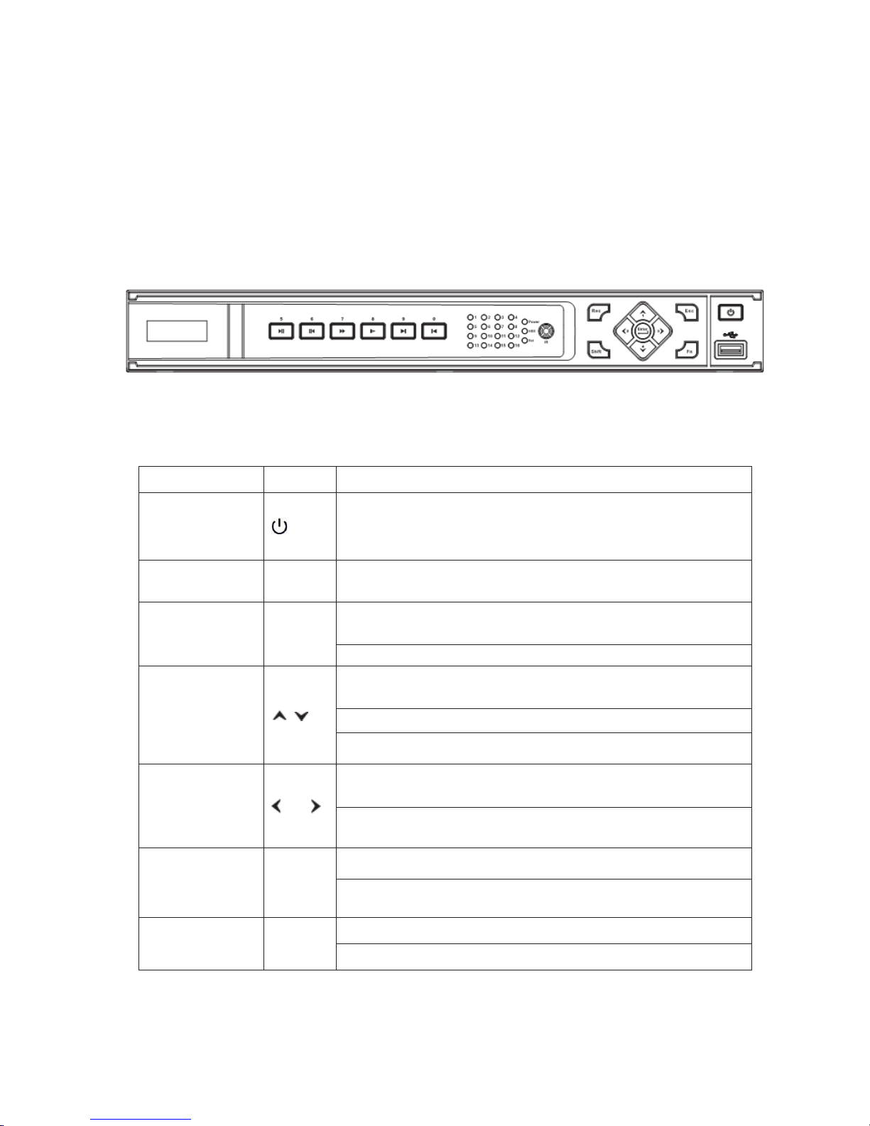
The -1U series NVR front panel is shown as below. See Figure 2-1.
Figure 2-1
Please refer to the following sheet for detail information.
Name
Icon Function
Power button
Power button, press thi s button for three seconds to b oot up or
shut down
NVR.
Number button
0-
9
Input Arabic number
Switch channel
Shift S
hift
In textbox, click this button to switch between numeral,
English(Small/Capitalized),donation and etc.
Enable or disable tour.
Up/
Down
Activate current control, modify setup, and then move up and
down.
Increase/decrease numeral.
Assistant function such as PTZ men
u.
Left/
Right
Shift current activated control, and then move left and right.
When playback, click these buttons to control playback bar.
ESC
ESC
Go to previous menu, or cancel current operation.
When playback, click it to restore real
-time monitor mode.
Enter
ENTER
Confirm current operation
Go to default button
Page 15

15
Go to menu
Record
REC
Manually stop/start recording, working with direction keys
or numeral keys to select the recording channel.
Slow play
Multiple slow play speeds or
normal playback.
Assistant
Fn
One-wi ndow monit or mode, cl ick thi s button to disp lay assistant
function: PTZ control and image color.
Backspace function: in numeral control or text control, press it for
1.5seconds to delete the previous character before the cursor.
In moti on detec tion se tup , w orki ng wi th Fn and dir ection k eys to
realize setup.
In text mode, click it to switch between numeral, English
character(small/capitalized) and etc.
In HDD management int erface, you can cl ick it to sw itch HDD
record information and other information (Menu prompt)
Realize other special functions.
Fast play
Various fast speeds and normal playback.
Play previous
x
In playback mode, playback the previous video
Play Next
x
In playback mode, playback the next video
Reverse/Pause
W
In normal playback or pause mode, click this button to reverse
playback
In reverse playback, click this button to pause playback.
Play/Pause
f
In normal playback click th
is button to pause playback
In pause mode, click this button to resume playback.
Window switch
Mult
Click it to switch one
-window/multiple-window.
USB port
To connect USB storage device, USB mouse.
Power indication
light
PWR
Power
indication light
Page 16

16
Record light
1-16It becomes on when system is recording.
IR Receiver
IR
It is to receive the signal from the remote control.
HDD abnormity
indicator
HDD
The red light is for the HDD
abnormity
Network
abnormity
indicator
Net
Th
e red light is for the network abnormity
Page 17

17
5HDU3DQHO
2.2.1 1 U Series
The 1U series NVR real panel is shown as in Figure 2-3.
Figure 2-3
Please refer to the following sheet for detailed information.
Port Name Connection Function
USB port. Connect to USB mouse.
Network port 10M/100M self-adaptive Ethernet port. Connect
to the
network cable.
RS232 232 debug
COM.
It is for general COM debug to configure IP
address or transfer transparent COM data.
HDMI High Definiti on
Multimedia
Interface
High definition video signal output port.
Transmit the clear video and multiple-track data
(Unc
ompressed)to the device of HDMI(High
definition media interface)
VGA VGA video
output port
VGA VGA video output port. Output analog video
signal. It can connect to the monitor to view
analog video.
116
Alarm input port.
116
I/O po
rt
z Four g roups of al arm input ports. The f irst
group
is from port 1 to port 4, the secon d
group is from port 5 to port 8, the third
g
roup
is from 9 to 12, and the four th g roup
is from 13 to 16. They are to receive the
signal from the external alarm source.
There are two types; NO (normal open)/NC
(normal close).
z When your alarm input device is using
ex
ter
nal power, please make sure the
device and the NVR have the same
ground.
Alar m input port
ground end
Al
arm input ground end.
Page 18

18
Port Name
Connection
Function
NO1
NO3
1-3-ch alarm
output port
z 3 groups of alarm output ports. (Group 1˖
port NO1 C1,Group 2:port NO2
C2,Group 3:port NO3C3˅
).Output alarm
signal to the alarm device. Please make
sure there is power to the external alarm
device.
NO
˖Normal open alarm output port.
z C˖Alarm output public end.
C1
C3
A
RS485
communication
port
RS485_A port. It is the cable A. You can
connect to the control devices such as speed
dome PTZ.
B
RS485_B.It is the cable B. You can connect to
the control devices such as speed dome PTZ.
Power port
Input 12V DC.
Power button
Power on/off button.
Page 19

19
0RXVH2SHUDWLRQ
Please refer to the following sheet for mouse operation instruction.
Left click
mouse
W
hen you have selected one menu item, left click mouse to view menu content.
Modify checkbox or motion detection status.
Click combo box to pop up dropdown list
Page 20
20
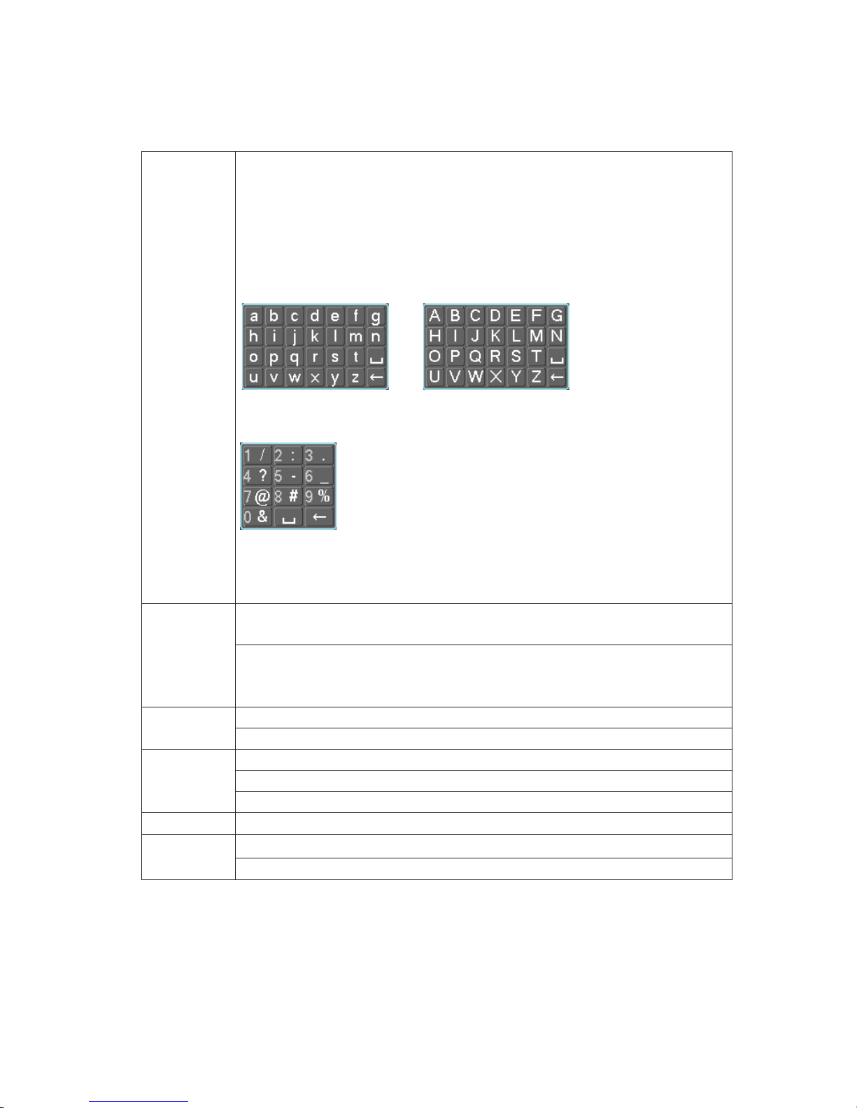
In input b ox, you c an sel ect i nput m et hods. Left c lic k the cor res ponding b utton
on the panel you ca n inp ut num er al/Eng li sh char acter ( sm all/cap ita li zed) . Her e
← stands for backspace button.
˻ stands for space button.
In Englis h input mode: _stands for input a backspace icon and ← stands for
deleting the previous character.
In numeral input mode: _ stands for clear and ← stands for deleting the
previous numeral.
When input special sign, you can click corresponding numeral in the front panel
to input. For example, click numeral 1 you can input“/” , or you can click the
numeral in the on-screen keyboard directly .
Double left
click mouse
Implement special control operation such as double click one item in the file list
to playback the video.
In multiple-window mode, double left click one channel to view in full-window.
Double left click curren
t video again to go back to previous multiple-
window
mode.
Right click
mouse
In real-time monitor mode, pops up shortcut menu.
Exit current menu without saving the modification.
Press middle
button
In numeral input box: Increase or decrease numeral value.
Switch the items in the check box.
Page up or page down
Move mouse
Select current control or move control
Drag mouse
Select motion detection zone
Select privacy mask zone.
Page 21
21
5HPRWH&RQWURO
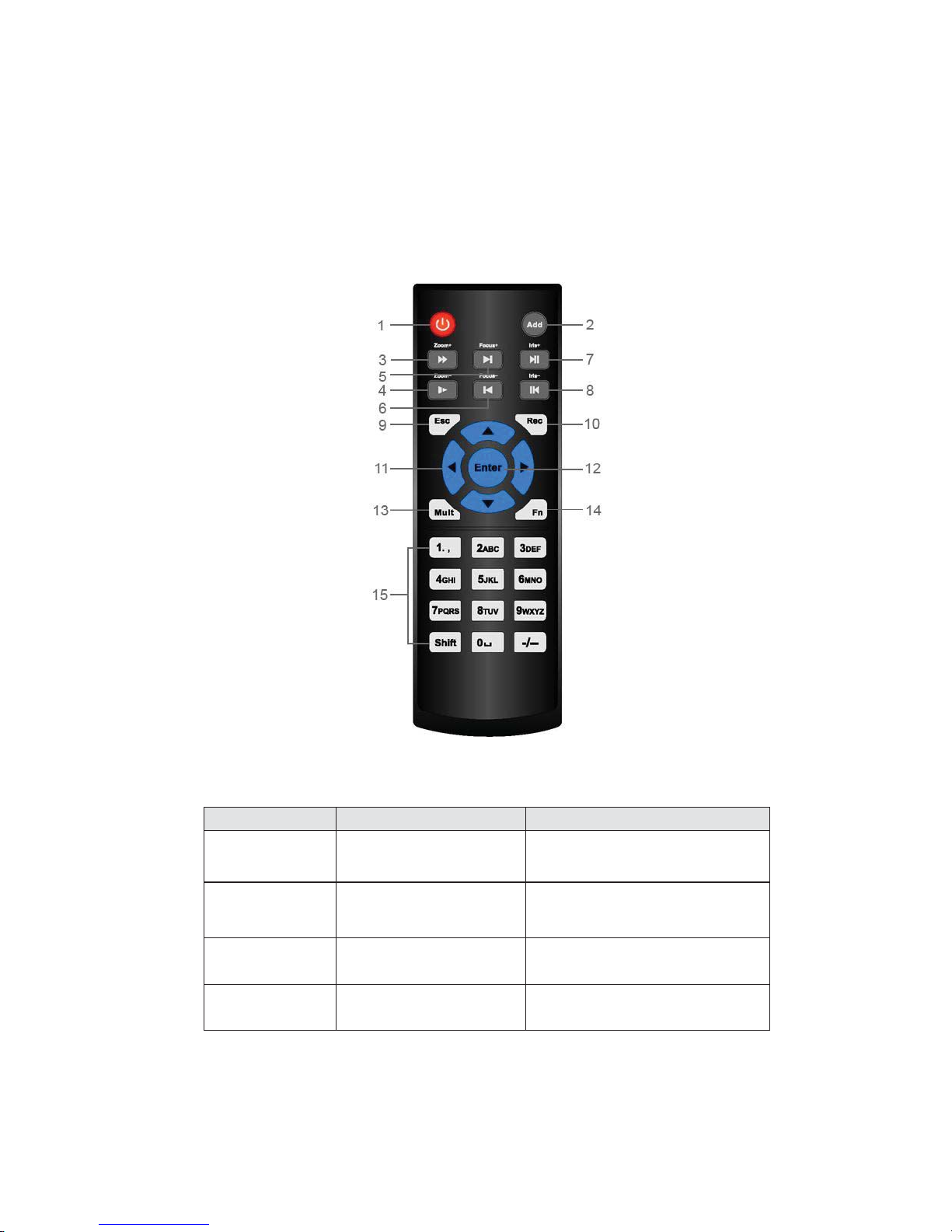
The remote control interface is shown as in X282H282H282HFigure 2-4X.
Please note remote control is not our standard accessory and it is not included in the accessory bag.
Figure 2-6
Please refer to the following sheet for detailed information.
Serial Number Name Function
1 Power button Click it to boot up or shut down
the device.
2 Address Click it to input device number, so
that you can control it.
3 Forward Various forward speeds and
normal speed playback.
4 Slow play Multiple slow play speeds or
normal playback.
Page 22

22
5 Next record
In playback mode, playback the
next video.
6 Previous record
In playback mode, playback the
previous video.
7
Play/Pause
In pause mode, click this button
to realize normal playback.
In normal playback click this
button to pause playback.
In real-time monitor mode, click
this button t o enter video searc h
menu.
8 Reverse/pause
Reverse playback pause mode,
click t his button t o reali ze nor mal
playback.
In reverse playback click this
button to pause playback.
9 Cancel
Go back to previous menu or
cancel current operation (close
upper interface or control)
10
Record
Start or stop record manually
In record interface, working with
the directi on butt ons to s elec t the
record channel.
C
lick this button for a
t least 1.5
seconds, system can go to the
Manual Record interface.
11
Direction keys
Switch current activated control,
go
to left or right.
In playback mode, it is to co ntrol
the playback process bar.
Aux function(such as switch the
PTZ menu)
12
Confirm /menu key
go to default button
go to the menu
13
Multiple-wind ow switch
Switch between multiple-window
and one-window.
14
Auxiliary key
In 1-ch monitor mode: pop up
assistant function
˖
PTZ control
Page 23

23
and Video color.
Switch the PTZ control menu in
PTZ control interface.
In motion detection interface,
working with direction keys to
complete setup.
15
0-9 number key
Input password, channel or
switch channel.
Shift is the button to switch the
input method.
Figure 2-1
Page 24

24
Page 25
25
1HWZRUN&RQQHFWLRQ
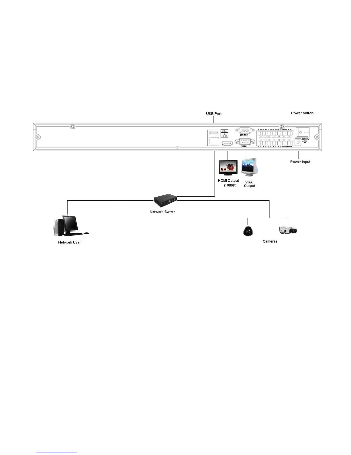
86HULHV&RQQHFWLRQ
Please refer to the following figure for 2U series connection.
.
Figure 4-1
Page 26

26
6\VWHP&DSDELOLW\
The max. system capability that this product series supports is 16-CH standard definition with
transmission rate 2mbps every channel or 4-ch high definition with transmission rate 8mbps.
The delay time for switch-in is under 500ms every channel.
Model System capability
4-ch series Max. sw itch-in: 4-channel s tandard def inition device wi th each channel max.
supports 2 Mbps or 2-ch 720P or 1-ch 1080P.
8-ch series Max. sw itch-in: 8-channel standard def inition device wi th each channel max.
supports 2 Mbps or 4-ch 720P or 2-ch 1080P.
16-ch series Max. sw itch- in: 16-c hannel standard d efini tion dev ice w ith each channel m ax.
supports 8-channel 720P /4Mbps or 4-ch 1080P.
Definition:
The standard definition device: the devices whose encoding resolution is under D1;
The high definition device: the devices whose encoding resolution is above 720P.
Page 27

27
*8,2SHUDWLRQ
Connect the device to the monitor, insert the mouse and connect the power cable. Push the on/off
button in the rear panel and then you can see the analog video output. You can use the mouse to
implement some simple GUI operation. Please refer to the following chapter for detail information.
All the operations listed below are based on our 16-ch series device.
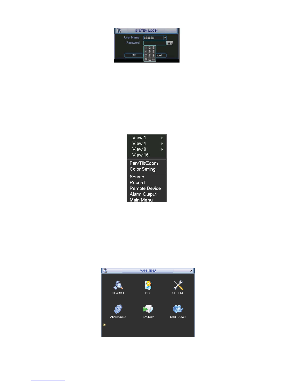
/RJLQ
After device booted up, the system is in multiple-channel display mode. See Figure 6-1.
You can overlay the corresponding date, time and channel name on each screen. You can refer to
the following sheet for channel record or alarm status information.
Figure 6-1
Right c lick m ouse, you ca n see t he login i nterf ace. Pl ease input user n ame and p assw ord. See
Figure 6-2.
System consists of four accounts:
z Username: admin. Password: admin.
z Username: 888888. Password: 888888.
z Username: 666666. Passwords: 666666.
z Username: default.
You can use USB mouse to input. Click
to switch between numeral, English character
(small/capitalized) and denotation.
Note:
For security reason, please modify password after you first login.
Within 30 m inutes , thr ee tim es login f ailur e will result i n system al arm and fiv e tim es logi n failure
will result in account lo
Recording status
Video loss
Motion detection
Camera lock
Page 28
28
Figure 6-2
5LJKW&OLFN0HQX
After you logg ed in the device, r ight click mous e, you can see the short cut menu. Please see
Figure 6-3.
Here you can set l ocal playback window, PTZ contr ol , vi deo c ol or, searc h r ec or ds , r em ot e device
and etc. The local playbac k w indow inc ludes 1/4/9/ 16. You can set the d etail c hannel amount in
1/4-window.
Figure 6-3
0DLQ0HQX
After you logged in, the system main menu is shown as below. See Figure 6-4. There are total six
icons: search, Information, setting, backup, advanced and shutdown. Move the cursor to highlight
the icon, then double click mouse to enter the sub-menu.
Figure 6-4
Page 29
29
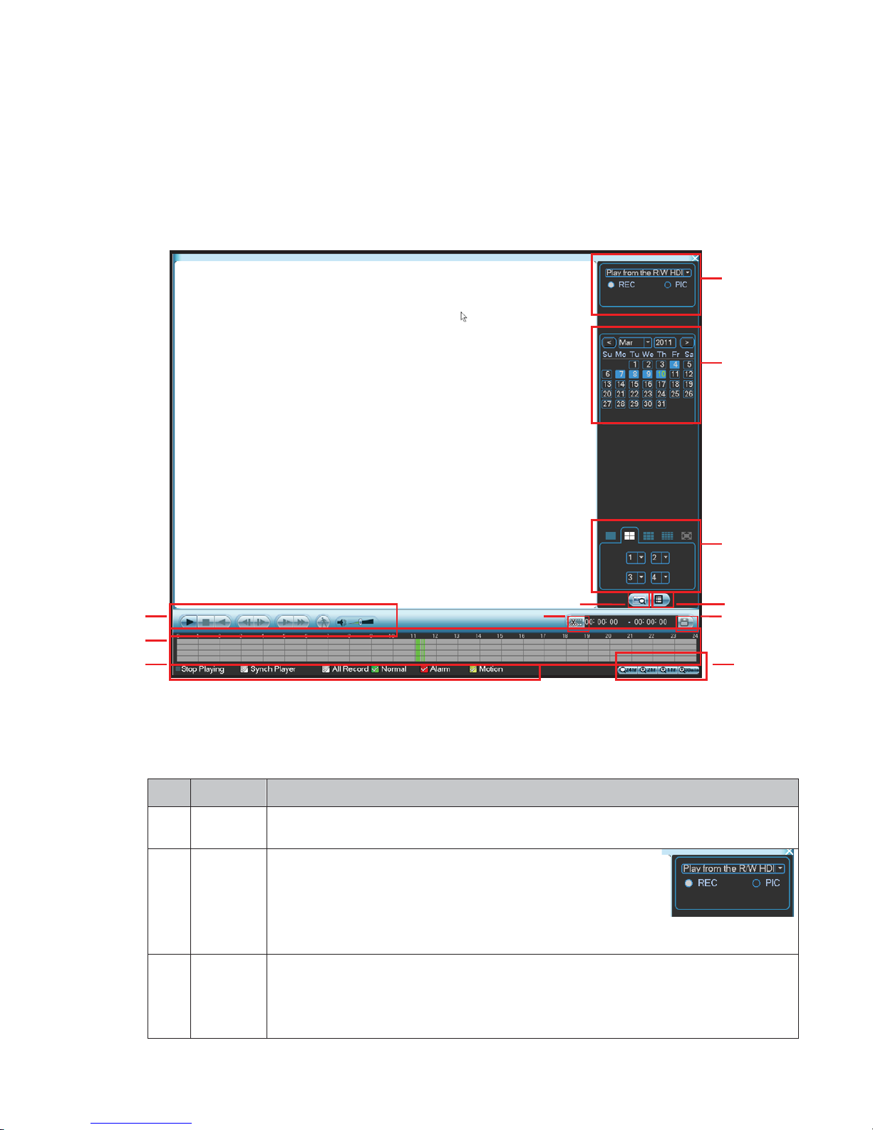
6HDUFK3OD\EDFN
Click search b ut ton i n the m ai n menu , s ear c h interface is show n as bel ow. See F ig ure 6- 5.
Usually ther e ar e three fi l e types:
z R: Regular recording file.
z A: External alarm rec ording fi l e.
z M: Motion detec ti on r ec ordi ng fil e
Figure 6-5
Please refer to the following s heet f or more inf ormati on.
SN
Name
Function
1
Display
window
z
Here is to display the searched picture or file.
z
Support 1/4/9/16-window playback.
2
Search
type
z
Here you can sel ect t o se arch t he p ict ure or t he rec orded
file.
zWhen ther e is dis played p ict ure on the left pane, yo u can
set the corresponding setup
3
Calendar
z
The blue hig hlighted date means there is pictur e or file. Otherwi se, there is no
picture
or file.
z
In any play m ode, cl ick the date you w ant to see, y ou can s ee the cor resp onding
record file trace in the time bar.
1
2
3
4
5
6
7
8
12
9
10
11
Page 30

30
4
Playback
mode
and
channel
selection
pane.
z
Playback mode˖1/4/9/16. (It may vary due to different series.)
In 1-window playback mode: you can select 1-16 channels.
In 4-window playback mode: you can select 4 channels according to your
requirement.
In 9-window playback mode, you can switch between 1-9 and 10-16
channels.
In 16-window playback mode, you can switch between1-16 and 17-32
channels.
z
The time bar will change once you modify the playback mode or the channel
option.
5
File list
switch
button
z
Double click it, you can view the picture/record file list of current day.
zThe file list is to display the first channel of the record file.
zThe system can disp l ay max 128 f i l es i n one time. U se t h e S/T or the
mouse to
view t he f i l e. Selec t one i t em, and th en do uble clic k the mouse or cl i c k the EN T ER
button
to playback.
zYou can input the period in the following interface to begin accurate search.
zFile type˖R—regular record ˗ A—external alarm record˗M—
Motion detect record.
6
Card
number
search
The card number search interface is shown as below.
7
Playback
control
pane.
►/
Play/Pause
There are three ways for you to begin playback.
z The play button
z Double click the valid period of the time bar.
z Double click the item in the file list.
In slow play mode, click it to switch between play/pause.
■
Stop
W
Backward play
In normal play mode, left
click the button, the file begins
backward play.
Click it again to pause current play.
In backward play mode, click ►/ to restore normal play.
│
W
/
X
│
In playback m ode, cl ick it to pl a y the next or the pr evi ous sec tion. You can
click
continuously
when you are watching the files from the same channel.
In normal play mode, when you pa use current p lay, you can cli ck
W│
and
│
X to begin frame by frame playback.
In frame by frame playback mode, click ►/ to restore normal playback.
►
Slow play
In playback mode, cli ck it to real ize
various slow
play modes such as slow
play 1, slow play 2, and etc.
Fast forward
In playback mode, click to realize various fast play modes such as fa st
play 1,fast play 2 and etc.
Note: The actual play speed has relationship with the software version.
Page 31

31
Smart search
The vol ume of the playbac k
Click the s naps hot b ut ton i n the full-scr een m ode, the system c an s napshot
1 picture per second.
8
Time bar
z
It is to display the record type and its period in current search criteria.
zIn 4-
window playback mode, there are corresponding four time bars. In other
playback mode, there is only one time bar.
zUse the m ous e to c l i c k one point of t h
e color z one in the ti me bar, system b egi ns
playback.
zThe tim e bar i s begi nning w ith 0 o'cl ock w hen you are setting the
configuration.
The ti me bar z ooms in th e pe rio d
of the
current playback time when you are playing
the file.
zThe green col or stands for t he regular recor d
file. The red color stands for the
external alarm record file. The yellow stands for the motion detect record file.
9
Time bar
unit
●The option inc ludes : 24H, 12H , 1H and 3 0M. The small er the unit, t he larg er the
zoom rate. You can accurately set the time in the time bar to playback the record.
zThe tim e bar i s begi nning w ith 0 o'cl ock w hen you are setting the
configuration.
The time b
ar zooms in the period of the
current playback time when you are playing
the file.
10
Backup
Select the file(s) you want to backup from the file list. System max supports files
from four channels. Then click the backup button, now you can see the backup
menu. Click the start button to begin the backup operat ion.
Check the file again you can cancel current selection.
System max supports to display 32 files from one channel.
11
Clip
z
It is to edit the file.
●Please pl ay the fi le you w ant to edi t and t hen cli ck this b utton w hen you w ant to
edit.
You
can see the cor resp onding sl ide bar in the tim e bar of t he correspondi ng
channel. You can adjust t he slide b ar or inp ut the acc urate tim e to set the f ile end
time. Click this button again and then save current contents in a new file. .
12
Record
type
In any play mode, the time bar will change once you modify the search type.
13
Smart
search
z
When system is playing, you can select a zone in the window to begin motion
detect. Click the motion detect button to begin play.
z Current button is null once the motion detect play has begun.
z The system will take the whole play zone as the motion detect region by
default.
z The motion detect play stopped once you switch the play file.
z Operations such as set time bar, click the play button, or any file list
operation
will stop current motion d etect play.
Other Functions
14
Other channel
synchronization switch to play
when playback
When playing the file, click the number button, system can
switch to the same
period of the corresponding channel
to play.
Page 32

32
15
Digital zoom
When the system is in full-scr een playback mode, left click
the mouse in the screen.
Drag
your mouse in the screen to
select a section and then left cl
ick mous e to realize
digital
zoom. You can right click mouse to exi t.
Note:
All the operations here (such as playback speed, channel, time and progress) have
relationship with hardware version. Some series NVRs do not support some functions or
playback sp eeds .
,QIRUPDWLRQ
Here is for you to view system information. There are total five items: HDD (hard disk information),
BPS (data stream statistics), Log and version, and online user. See Figure 6-6.
Figure 6-6
6.5.1 HDD Information
Here is to list hard disk type, total space, free space, and status. See Figure 6-7.
For 1U series product there are max 2 HDDs. For S series product there are max 8 HDDs.
○ means current HDD is normal.. - means there is no HDD.
If disk is damaged, syst em show s as “?”. Pl ease r emove the br oken h ard di sk b efor e you add a
new one.
Page 33

33
Figure 6-7
In Figure 6-7, click view record d time button, HDD record time information interface is shown as
in Figure 6-8.
Figure 6-8
Parameter Function
SATA
1-4 here means there are 4 HDDS.
Fo
r 1U series pr oduct there ar e max 2 H DDs. For 2U ser ies p roduc t ther e
are max
8 HDDs.
When HDD is working properly, system is shown as O. . “_” means there is
no HDD.
SN You can view the HDD amount the device connected to;
γ means the second HDD is current working HDD.
Type The corresponding HDD property .
Total space The HDD total capacity.
Free space The HDD free capacity.
Status HDD can work properly or not.
Page up Click it to view previous page.
Page down Click it to view the next page.
View
recording time
Click it to view HDD record information (file start time and end time).
View HDD
type and
capability
Click it to view HDD property, status and etc,
6.5.2 BPS
Here is f or you to v i ew cur rent v ideo data str eam (KB/s) and occup ied h ard di sk s torag e (M B/h).
See Figure 6-9.
Page 34

34
Figure 6-9
6.5.3 Log
Here is for you to view system log file. Syst em lists the following information. Se e Figure 6-10.
Log types include system operation, configuration operation, data management, alarm event,
record operation, log clear and etc.
Please select start time and end time, then click search button. You can view the log files.
System max displays 100 logs in one page. It can max save 1024 log files.
Please page up/down button to view if there are more than ten files.
System also supports the backup function; yo u can click the backup button to save the log files in
the USB devices.
Figure 6-10
Click t he Details button or doub le click the log item, you can v iew the detailed inf ormation. See
Figure 6-11.
Page 35

35
Figure 6-11
6.5.4 Version
Here is for you to view some version information. See Figure 6-12.
z Channel
z Alarm in
z Alarm out
z System version:
z Build Date
z Web
z Serial number
Figure 6-12
6.5.5 Online Users
Here is for you manage online users connected to the local device. See Figure 6-13.
You can disconnect one user or block one user if you have proper system right.
Page 36

36
Figure 6-13
6HWWLQJ
In main menu, highlight setting icon and double click mouse. System setting interface is shown as
below. See Figure 6-14.
Figure 6-14
Important
Please note you need to have the proper right to implement the following operation.
6.6.1 General
General setting includes the following items. See X357H357H357HFigure 5-3X.
z System time: Here is for you to set system time
z Date format: Ther e ar e three types: YYYYY-M M -DD: MM- DD- YYYYY or DD-MM- YYYY.
z Date separator : There are three denotat i ons t o sep ar ate date: dot, beeline and solidus .
z DST: Here you can set DST time and date. Pl ease enable DST functi on and then c l i ck s et
button. You can see an i nter face is shown as i n Figure 6-16. H er e you can s et s tar t tim e and
end time by set ti ng c orr espondi ng week setup. In Fig ur e 6- 16, enabl e date button, you can
see an interf ace i s s hown as i n Figure 5- 5. Here you can set s tar t t ime and end tim e by
setting corresponding date setup.
z Time form at: There ar e two types: 24 - hour m ode or 12 - hour mode.
Page 37

37
z Language: Syst em s uppor ts various l anguag es : Chinese ( s im plif i ed), C hinese ( Tr adi tional ) ,
English, Ital i an, J apanes e, Fr ench, Spani s h ( All languages listed here are op tional . Slight
difference maybe found in various series.)
z HDD full: Here is for you to select working mode when hard disk is full. There are two options:
stop recording or rewrite. If current working HDD is overwritten or the current HDD is full while
the next HDD is no empty, then system stops recordi ng , If the c urr ent HDD is full and then
next HDD is not emp ty, then s ystem overwrites the previous files.
z Pack duration: H ere is for you to s p ec if y rec ord dur ati on. The v al ue rang es fr om 60 to 120
minutes. Default value is 60 minutes.
z NVR No: When you are us i ng one r em ote control (not incl uded in the ac ces sor y bag) to
control sev eral N VRs, you can g ive a name to each N VR f or your manag ement.
z Video standard: Ther e ar e tw o formats: NTSC and PAL.
z Auto logout: H ere i s f or you to set auto l ogout interval once l ogi n us er rem ains i nactiv e for a
specified tim e. Val ue ranges from 0 to 60 minutes .
z Startup wizard: Once you check the box here, system will go to the startup wizard directly
when the s ystem res tar ts the nex t t ime. Otherw i s e, it will go to the login interface.
z Device ID: Pl eas e inp ut a c orr esp ondi ng devic e nam e her e.
Note:
Since system tim e is v er y important, do not modify tim e cas uall y unles s t her e is a m ust!
Before your tim e m odifi c ation, pl eas e st op r ecord operation first!
After completing all the setups please click save button, system goes back to the previous menu.
Figure 6-15
Figure 6-16
Page 38

38
Figure 6-17
6.6.2 Encode
Encode setting i ncludes the f ol l owing i tems . See Figure 6-18.
Please note some s eri es do not s upp ort ex tr a s tream.
z Channel: Select the c hannel you w ant .
z Type: Please sel ect fr om the dr opdown list. Ther e ar e thr ee op tions : regular/motion
detect/alarm. You can set the vari ous encode parameters for different r ec or d t ypes.
z Compression: System supports H.264.
z Resolution: The mainstream resolution type is IPC’s encoding config. G ener ally ther e ar e
D1/720P/1080P.
z Frame rate: It r anges from 1f/ s t o 25f/s in N TSC mode and 1f /s to 30f/s in PAL mode.
z Bit rate type : System s uppor ts tw o types : CBR and VBR. In VBR mode, you can set v i deo
quality.
z Quality: There ar e si x l evels rangi ng from 1 to 6. The six th l ev el has t he hig hest imag e
quality.
z Video/audio: You c an enable or di s abl e t he video/ audi o.
z Overlay: Cli ck overl ay b utt on, you can s ee an i nter face is shown in Fig ure 6- 19.
Cov er area (Privacy mask): Here is for you to set privacy mask s ection. You can dr ag you
mouse to set pr oper secti on si ze. In one channel v i deo, s ystem max supports 4 zones in one
channel.
Prev i ew/m oni tor: priv ac y mask has tw o t ypes . Previ ew and M onitor . Prev i ew m eans the
privacy mask z one c an not be viewed by user w hen system is in previ ew status . Monitor
means the priv acy mas k zone c an not be view by the user when system is in monitor status .
Time display: You can select system displays time or not when you playback. Please click set
button and then dr ag the title to t he corr esp ondi ng pos i tion i n the s cr een.
Channel di sp l ay: You can sel ect syst em displays channel numb er or not when you playbac k .
Please click set button and t hen dr ag t he ti tl e to t he corr esp ondi ng pos i tion i n the s creen.
Please highl ight icon
to select the c orr esp ondi ng function.
Page 39

39
Figure 6-18
Figure 6-19
6.6.3 Schedule
In the main m enu, fr om set ting to schedul e, you ca n g o t o sc hedul e m enu. See Fig ure 6- 20.
z Channel: Please select the channel number first. You can select “all” if you want to set for the
whole channels.
z Week day: There are ei g ht op tions : r anges from Satur day to Sund ay and al l .
z Pre-recor d: System can pre-record the video before the ev ent occ urs i nto the f i l e. The val ue
ranges from 1 to 30 s ec onds dependi ng on the bit stream.
z Redundancy: System supports r edundanc y b ac k up func ti on. It all ow s you b ackup rec orded
file in tw o disks. You can highlight Redundancy but ton to activate this function. Pleas e note,
before enable t hi s f unction, pl ease s et at l east one HDD as redundant. (Mai n
menu->Advanced->HDD Management)
z Snapshot: You can enabl e thi s function to snapshoot image when alarm oc curs.
z Record types : Ther e ar e f our types: r egul ar, m otion detecti on ( MD ) , Alarm , MD & alarm.
Please highlight icon
to select the corresponding function. After completing all the setups
please click sav e butt on, s ystem goes back to t he pr evious menu.
At the bottom of the menu, there are color bars for your ref erence. Green color stands for
regular recording, yellow color stands for motion detection and red color stands for alarm
recordi ng. The white means the MD and alarm recor d is valid. Once you hav e set t o recor d
when the MD and alarm occurs , system will not recor d neither motion detect occur s nor the
alarm occu rs.
Page 40

40
Figure 6-20
Shortcut settings:
Users can copy the set ti ng s of channel A to c hannel B to ac hi eve t he sam e c onfig urat i on
effect.E.g. choos e c hannel 1 and click t he copy b utton af ter relevant setti ngs are done, then
paste to channel 3 , you can find that the configuration of channel3 i s the s ame as that of
channel1.
Users can sav e the c onfig ur ation of each c hannel r esp ec tiv ely or s av e the c onfig ur ation
all at once ul t imat el y.
6.6.4 RS232
RS232 interf ac e is s how n as bel ow. There are fiv e item s. See Figure 6-21.
z Function: There are various devi ces f or you to sel ect . Cons ol e is f or you to use t he C OM or
mini-end sof tw are to upgrade or debug the pr ogr am. The cont r ol keyb oar d is for you to
control the devi c e vi a the sp eci al keyboard. Tr ansparent COM (adapter) is to connect to t he
PC to transfer data directly. Pr ot ocol COM is for card ov erl ay function. Netw ork keyb oar d is
for you to use the s p ecial k eyb oard to cont r ol the devi ce. PTZ m atrix i s t o connect to t he
peripheral matrix control.
z Baud rate: You can sel ec t pr op er baud rate.
z Data bit: You can sel ect proper data bi t. The value rang es from 5 t o 8.
z Stop bit: Ther e ar e thr ee v alues: 1/1.5/ 2.
z Parity: there ar e five choices : none /odd/ even/space mark.
System default s etup is:
z Function: Console
z Baud rate:115200
z Data bit:8
z Stop bit:1
z Parity: None
After completing all the setups please click save button, system goes back to the previous menu.
Page 41

41
Figure 6-21
6.6.5 Network
Here is for you to input network information. See Figure 6-22.
z IP address: H ere you can input IP address.
z DHCP: It is to auto searc h IP. When enable DHCP functi on, you can not m odif y IP/Subnet
mask /Gatew ay. These values are from DHCP functi on. I f you hav e not enab l ed DH C P
function, I P/Subnet m ask/G atew ay disp l ay as z er o. You need to disable DHCP function t o
view current IP informati on. Besides, when PPPoE is op erating, you can not modify
IP/Subnet mask /Gateway.
z TCP port: Default value is 37777.
z UDP port: Default value is 37778.
z HTTP port: D efaul t val ue i s 80.
z RTSP port: Def a ul t v alue is 554.
z Max connecti on: system support maximal 20 us ers. 0 m eans ther e i s no c onnect i on limi t.
z Preferred DN S server: DNS server IP addres s .
z Alternate DNS server: DNS server al ter nat e addr ess.
z Transfer mode: H ere you can s el ec t the priority between fluenc y/video quali ties.
z LAN download: System can process the downloaded data first if you enable this function. The
download speed i s 1.5X or 2. 0X of t he normal sp eed.
After completing all the setups please click save button, system goes back to the previous menu.
Page 42

42
Figure 6-22
6.6.5.1 Adv anced Setup
Advanced setup interface is shown as in Figure 6-23. Please draw a circle to enable
corresponding function and then double click current item to go to setup interface.
Figure 6-23
6.6.5.2 I P F ilter
IP filter interface is shown as in Figure 6-24. Y ou can add IP in the following list. The list supports
max 64 IP addresses.
Please note after you enabled this function, only the IP listed below can access current NVR.
If you disable this function, all IP addresses can access current NVR.
Figure 6-24
Page 43

43
6.6.5.3 N TP Se tup
You need to install SN T P ser ver ( Such as Ab s ol ute Time Serv er ) in your PC first. In Wi ndow s XP
OS, you can use command “net start w32time” to boot up NTP service.
NTP setup interface is shown as in Figure 6-25.
z Host IP: Input your PC address.
z Port: This series NVR supports TCP transmission only. Port default value is 123.
z Update interval: minimum value is 1. Max value is 65535. (Unit: minute)
z Time zone: select your corresponding time zone here.
Here is a sheet for your time zone setup.
City /Region Name Time Zone
London GMT+0
Berlin GMT+1
Cairo GMT+2
Moscow GMT+3
New Deli GMT+5
Bangkok GMT+7
Beijing (Hong Kong) GMT+8
Tokyo GMT+9
Sydney GMT+10
Hawaii GMT-10
Alaska GMT-9
Pacific Ti me(P.T) GMT-8
American Mountain Time(M.T) GMT-7
American Central Time(C.T) GMT-6
American Eastern Time(E.T) GMT-5
Atlantic Time GMT-4
Brazil GMT-3
Middle Atlantic Time GMT-2
Figure 6-25
6.6.5.4 Multiple Cast Setup
Multiple-cast setup interfac e is shown as in Figure 6-26.
Page 44

44
Figure 6-26
Here you can set a multiple cast group. Please refer to the following sheet for detailed information.
z IP multiple cast group address
-224.0.0.0-239.255.255.255
-“D” address space
z The higher four-bit of the first byte=”1110”
z Reserved local multiple cast group address
-224.0.0.0-224.0.0.255
-TTL=1 When sending out telegraph
-For example
224.0.0.1 All systems in the sub-net
224.0.0.2 All routers in the sub-net
224.0.0.4 DVMRP router
224.0.0.5 OSPF router
224.0.0.13 PIMv2 router
z Administrative scoped addressees
-239.0.0.0-239.255.255.255
-Private address space
z Like the single broadcast address of RFC1918
z Can not be used in Internet transmission
z Used for multiple cast broadcast in limited space.
Except the ab ove mentioned addr esses of sp ecial meaning, you can use other addresses. For
example:
Multiple cast I P: 235.8.8.36
Multiple cast PORT: 3666.
After you logged in the Web, the Web can automatically get multiple cast address and add it to the
multiple cast groups. You can enable real-time monitor function to view the view.
Please note multiple cast function applies to special series only.
6.6.5.5 PPPoE
PPPoE interface is shown as in Figure 6-27.
Input “PPPoE name” and “PPPoE password” you get from your ISP (Internet service provider).
Click save button, you need to restart to activate your configuration.
After rebooting, NVR will connect to internet automatically. The IP in the PPPoE is the NVR
dynamic value. You can access this IP to visit the unit.
Page 45

45
Figure 6-27
6.6.5.6 DDNS Setup
DDNS setup interface is sho wn a s in Figure 6-28.
You need a PC of fixed I P in the inter net and th ere i s the DDNS software running in this PC. In
other words, this PC is a DNS (domain name server).
In network DDNS, please select DDNS type and highlig ht enable item . Them please input your
PPPoE name you get f rom you IPS and serv er IP (PC wi th DDNS ) . Click save button and then
reboot system.
Click save button, system prompts for rebooting to get all setup activated.
After rebooting, open IE and input the domain name.
Now you can open DDNSServer web search page.
Figure 6-28
Please n ote NNDS t ype includes: CN99 DDNSǃNO-IP DDNSǃPrivate DDNSǃDyndns DDNS and
sysdns DDNS . All th e DDNS can be valid at the same time, you can select as you requirement.
Private DDNS fun ctio n sh all work with special DDNS server and special Professional Surveillance
Software (PSS).
6.6.5.7 U PNP
The UPNP protocol is to establish a mapping relationship between the LAN and the WAN. Please
input the r outer IP address i n the LAN i n F i g ur e 6- 22. D ouble click t he UP N P item i n Fi g ure 6-22,
you can see the following interface. See Figure 6-29.
z UPNP on/off ˖Turn on or off the UPNP function of the device.
Page 46

46
z Status: When the UPNP is offline, it shows as “Unknown”. When the UPNP works it shows
“Success”
z Router LAN IP: It is the router IP in the LAN.
z WAN IP: It is the router IP in the WAN.
z Port Mapping list˖ The port mapping list here is the one to one relationship with the router’s
port mapping sett in g.
z Enable Switch
: ˖It shows that the function of port mapping is enabled in this port.
z List˖
Service name˖Defined by user.
Protocol˖ Protocol type
Internal port˖Port that has been mapped in the router.
External port˖Port that has been mapped locally.
z Default: UPNP default port setting is the HTTP, TCP and UDP of the NVR.
z Add to the list: Click it to add the mapping relationship.
z Delete: Click it to remove one mapping item.
Double click one item; you can change the corresponding mapping information. See Figure 6-30.
Important:
When you are setting the router external port, please use 1024~5000 port. Do not use
well-known port 1~255 and the system port 256~1023 to avoid conflict.
For the TC P and U D P, please make sur e t h e in t ernal p o r t and ext ern al p o r t are th e same to
guarantee the proper data transmission.
Figure 6-29
Page 47

47
Figure 6-30
6.6.5.8 Em ail
The email interface is shown as below. See Figure 6-31.
z SMTP server: Please input your email SMTP server IP here.
z Port: Please input corresponding port value here.
z User name: Please input the user name to login the sender email box.
z Password: Please input the corresponding password here.
z Sender: Please inp ut se nder email box here.
z Title: Please input email subject here. System support English character and Arabic number.
Max 32-digit.
z Receiver: Please input receiver email address here. System max supports 3 email boxes.
z SSL enable: System supports SSL encryption box.
z Interval: The send interval ranges from 0 to 3600 seconds. 0 means there is no interval.
z Health email enable: Please check the box here to enable this function. This function allows
the system to send out the test email to check the connection is OK or not.
z Interval: Please check the above box to enable this function and then set the corresponding
interval. System can send out the email regularly as you set here. Click the Test button, you
can see the corresponding dialogue box to see the email connection is OK or not. See
Figure 6-32.
Please note s ystem will not send out the em ail imm ediately when the alar m occurs . When the
alarm, m otion detection or the abnormi ty event activ ates the em ail, system sends out the em ail
according to the interval you speci f i ed her e. Th is func ti on i s very useful w hen t her e ar e too many
emails activated by the abnormity events, which may result in heavy load for the email server.
Page 48

48
Figure 6-31
Figure 6-32
6.6.5.9 F TP
You need to download or buy FTP serv ice tool (such as Ser -U FTP SERVER) to estab lish FTP
service.
Please install Ser-U FTP SERVER first. From “start” -> “program” -> Serv-U FTP Server -> Serv-U
Administator. Now you can set user password and FTP folder. Please note you need to grant write
right to FTP upload user. See Figure 6-33.
Figure 6-33
You can use a PC or FTP login tool to test setup is right or not.
For example, you can login user ZHY to
H140H140H140HTUFTP://10.10.7.7UTH and then test it can modify or delete
folder or not. See Figure 6-34.
Page 49

49
Figure 6-34
System als o supports upl oad multiple NVRs to one FTP serv er. You can creat e mul tiple folder s
under this FTP.
In Figure 6-22, select FTP and then double click mouse. You can see the following interface. See
Figure 6-35.
Please highlight the icon
in front of Enable to activate FTP function.
Here you can input FTP server address, port and remote directory. When remote directory is null,
system automatically create folders according to the IP, time and channel.
User name and password is the account information for you to login the FTP.
File length is upload file length. When setup is larger than the actual file length, system will upload
the whole file. When setup here is smaller than the actual file length, system only uploads the set
length and auto ignore the left section. When interval value is 0, system uploads all corresponding
files.
After completed channel and weekday setup, you can set two periods for one each channel.
Click t he Test button, you c an s ee th e cor resp ondin g di alog ue box to s ee th e F TP c onnect ion is
OK or not. See Figure 6-36.
Figure 6-35
Figure 6-36
6.6.5.1 Al arm center
Interface is pre-reserved for the users to develop this function.
Page 50

50
6.6.6 Alarm
In the main menu, fr om Sett i ng to Al arm, you can s ee al arm setup interface. See Figur e 6- 37.
Alarm setup:
Alarm interface is shown as below . See Figure 6- 37.
z Alarm in: Here is for you to select channel number.
z Event type: Ther e ar e two types. One is local input and the other is network input.
z Type: norm al op en or normal close.
z PTZ activati on: H ere you can set PTZ movement when al arm occurs . Suc h as go to pr es et,
tour& pattern when there is an alarm. Click “select” button, you can see an interface is shown
as in Figure 6-38.
z Period: Click s et b utton, you can s ee an i nterface is show n as i n Figur e 6-39. H er e you can
set for busi ness day and non-busi ness day. In F i gur e 6- 39, c lic k set b utton, you can see an
interface i s shown as in F ig ure 6-40. Here you can set your own setup for busines s day and
non-business day.
z Anti-dit her : Here you can set anti-dit her tim e.
z Show message: Syst em c an pop up a mes sag e to alarm you in the local hos t screen if you
enabled this func tion.
z Alarm upload: System can upload the alarm signal to the network (including alarm centre)
if you enabl ed curr ent func ti on.
z Send email: System c an s end out em ail to al er t you w hen al arm occurs.
z Record channel : you can s el ec t pr oper channel to r ec or d al arm video (Multiple choices) . At
the same tim e you need to s et alarm recor d in s c hedule int erface (Main
Menu->Set ting-> Sc hedul e) and s el e c t schedul e record in manual rec ord i nterface (Main
Menu->Advance->Manual Record).
z Latch: Here is for you to set proper delay duration. Value ranges from 10 to 300 seconds.
System automati call y delays sp ec ifi ed sec onds in turning off al arm and act iv at ed output after
external al arm canc ell ed.
z Tour: Here you can enab l e tour f unc ti on w hen al arm occ urs. System supports one-window
tour. Please go to chapter 5.3.9 Display for t our i nterv al set up.
z Buzzer: Highl ig ht the ic on to enab l e t hi s function. The buzz er be eps w hen al arm occur s .
For snapshot op erat i on, pl eas e ref er to c hapter 4.4.2.
Please highlight icon
to select the corresponding function. After setting all the setups
please click sav e butt on, s ystem goes bac k to the pr evi ous menu.
Page 51

57
Figure 6-37
Figure 6-38
Figure 6-39
Figure 6-40
Page 52

58
6.6.7 Detect
Go to Detect Menu
In the mai n menu, from Setting to Detect, you can see m otion detect inter face. See Figure
6-41.There is thr ee detec ti on t ypes : motion detection, v i deo l oss, c amera mas king.
Motion Detect
Detection menu is shown as below. See Figure 6-41
z Event typ e: from t he dr opdow n li st you can sel ec t moti on det ect i on typ e.
z Channel: select the channel to activate recording function once alarm occurred. Please make
sure you have s et MD r ecord in encode i nterface(Main Menu - > Setting -> Sc hedul e) and
schedule record in manual record interface(Main Menu->Advanced->Manual Record)
z Latch: w hen moti on det ect i on compl ete, syst em auto delays detec ti ng for a specified time.
The value ranges f r om 10 - 300(U ni t: s econd)
z Region: Clic k sel ect butt on, the i nt erf ac e is s how n as in Figure 6- 42. Here you can s et
motion detecti on z one. Ther e ar e 396( PAL) / 330(NTSC) small zones. The green z one i s
current curs or p osi ti on. Grey zone i s the motion detecti on z one. Bl ac k zone is t he di sarmed
zone. You can cli c k Fn b utton t o swi tch b etween the arm mode and di s arm mode. In arm
mode, you can clic k the dir ec ti on butt ons t o m ov e the gr een r ec tangl e t o set the moti on
detection zone. After you comp l eted the s etup, pl ease cl i ck EN TER but ton to ex i t curr ent
setup. Do remember click save button to save current setup. If you click ESC button to exit
the region s etup i nterf ace s ystem will not save your z one s etup.
z Sensitivity: System supports 6 l ev els. The si x th l evel has the hi ghest sensitivit y.
z Show message: System can pop up a mess age to alarm you in t he l ocal hos t screen if you
enabled this f unc tion.
z Alarm upload: System can upload the alarm signal to the network (including alarm centre)
if you enabl ed c urr ent func ti on.
z Send email: Syst em can s end out email to alert you when al arm occurs .
z PTZ activati on : H ere you can s et PTZ movement when al arm occ urs. Such as go to pr es et,
tour &pattern when there is an alarm. Click “select” button, you can see an interface is shown
as in
X305H305H305HFigure 6-43X.
z Period: Click s et b utton, you can s ee an i nterface is show n as i n Figur e 6-44. H er e you can
set for busi ness d ay and non - b us i ness day. In F i gur e 6- 44 c lic k set button, you can see an
interface i s shown as in F ig ure 6-45. Here you can set your own setup for busines s day and
non-business day.
z Anti-di ther : Here you can s et anti-di ther tim e.
z Alarm output: when alarm occurred, system enables peripheral alarm dev i ces.
z Tour: Here you can enab l e tour f unc ti on w hen al arm occ urs. System one-wi ndow tour.
Please go t o chapt er 5.3.9 Display f or tour interval setup.
z Snapshot: You can enabl e thi s function to snapshoot image when alarm occurs.
Please highlig ht icon to s elect the correspondi ng function. Af ter all the setups pleas e click
save button, system goes back to the previous menu.
Note:
In motion detection m ode, you can not use copy/paste to set channel setup since the video i n
each channel may not b e the s am e.
In Figure 6-42, you can left click mouse and then drag it to set a region for motion detection. Click
Page 53

59
Fn to switch b etween arm /wi t hdr aw moti on detec tion. After setting, click enter button to exi t.
Figure 6-41
Figure 6-42
Figure 6-43
Page 54

60
Figure 6-44
Figure 6-45
Video Loss
In Figure 6- 41, select v ideo los s from the type li st. You can see the interf ace is shown as in
CFigure 6- 46.Thi s f unc tion al l ows you to be informed when v i deo l oss phenom enon occurred.
You can enable al arm output channel and then enable show message function.
Tips:
You can enable pr es et activation op erat i on w hen video l os s occurs.
Please refer to c hapter 4. 5.2 m otion detec ti on f or detail ed i nformation.
CFigure 6-46
Page 55

61
Camera Mas k ing
When someone viciously masks the lens, or the output video is in one-color due to the
environment s light change, the system can alert you to guar antee video continuity. Camer a
masking interface is shown as in Figure 6-47.
Tips:
You can enable pr es et/t our /patt er n activation operati on w hen v i deo l os s occurs.
Please refer to c hapter 4. 5.2 m otion detec ti on f or detail ed i nformation.
Note:
In Detect int erface, copy/p aste f unction is only valid for t he same t ype, which m eans you can
not copy a channel s etup i n vi deo l oss mode to c am er a mas king mode.
Figure 6-47
6.6.8 PTZ
Note: All the operations here are based on PELCOD protocol. For other protocols, there might
be a little diff erenc e.
Cable Connection
Please foll ow the pr ocedures below to go on cable connecti on
z Connect the dom e RS485 port to N VR 485 p or t .
z Connect dome vi deo out p ut c able to NVR vi deo inp ut por t.
z Connect pow er adap ter t o the dom e.
PTZ Setup
Note: The camera video should be in the current screen. Before setup, please check the
following connections are right:
z PTZ and decoder connecti on i s r ig ht. Decoder addres s s etup is rig ht.
z Decoder A (B) li ne c onnect s wi th NVR A (B) li ne.
Boot up the NV R , inp ut us er nam e and p assword.
In the main menu, c lick set ting, and t hen click Pan/Til t Contr ol button. The i nterf ace is s hown
as in Figure 6-48. Here you can set the following items:
Page 56

62
z Channel: sel ec t t he current camera channel .
z Protocol: s elect c orr esp ondi ng PTZ pr otoc ol( suc h as PELCO D)
z Address: default address is 1.
z Baud rate: sel ec t c orr espondi ng b aud rate. D efaul t v alue i s 9600.
z Data bits: s el ect corresponding data bi ts. Default value is 8.
z Stop bits : selec t corr esp ondi ng st op bi ts. D efaul t value is 1.
z Parity: ther e ar e thr ee options: odd/ev en/none. D ef aul t set up is none.
Figure 6-48
After completi ng al l t he set ting please click save butt on.
In one window display mode, right click mouse (click “Fn” Button in the front panel or click “Fn”
key in the remote control).
Click Pan/Tilt/Z oom, the i nt erf ac e i s shown as below. See Figur e 6-49.
Here you can set the following items:
z Step: value ranges fro 1 to 8.
z Zoom
z Focus
z Iris
Please click ic on
and to adjust zoom, focus and iris.
Figure 6-49
In Figur e 6-49, please click direc tion arrows to adjust PTZ p osition. Ther e are to tal 8 directi on
arrows.
Page 57

63
Figure 6-50
Here is a sheet for you reference.
Name
Function
key
function
Shortcut
key
Function
key
function
Shortcut
Key
Zoom
Wide
Far
Focus
Near
ū
ū
_
Far
►
ū
Iris Close
W
Open
f
6.6.9 Display
Display setup interface is shown as below. See Figure 6-51.
z Transparency: Here is for you to adjust transparency. The value ranges from 128 to 255.
z Channel name: Here is for you to modify channel name. System max support 25-digit (The
value may vary due to different series). Please note all your modification here only applies to
NVR local end. You need to open web or client end to refresh channel name.
z Time display: You can select to display time or not when system is playback.
z Channel display: You can select to channel name or not when system is playback.
z Resolution: There are four options: 1280h1024(default),1280h720,1024h768,800h600.
Please note the system needs to reboot to activate current setup.
z Enable tour: Activate tour function.
z Interval: System supports 1/4/8/9/16-window tour. Input proper interval value here. The value
ranges from 5-120 seconds. In tour process, you can use mouse or click Shift to turn on
window switch function.
Stands for opening switch function, stands for closing
switch function.
z Monitor tour type: System support 1/8-window tour.
z Alarm tour type: System support 1/8-window tour.
Please highlig ht icon
to select the c orr esp ondi ng function.
After completing all the setups please click save button, system goes back to the previous menu.
Page 58

64
Figure 6-51
In Figur e 6-51, click m odify button after c hannel. You can see an interface show n as in Fi gure
6-52. Please note all your modific ati on her e ap plies to local end onl y. You need to ref r es h web or
client-end to get the latest channel name. System max support 25-digital character.
Figure 6-52
In tour m ode, you c an see t he foll owing inter face. O n the ri ght corner, ri ght cli ck mous e or clic k
shift button, you can control the tour. There are two icons:
stands for enabling window switch
and
stands for disabling window function. See Figure 6-53.
Figure 6-53
6.6.10 Default
Click default icon, system pops up a dialogue box. Y ou can highlight to restore default factory
setup.
z Select all
z General
z Encode
z Schedule
z RS232
z Network
z Alarm
z Detect
z Pan/tilt/zoom
z Display
z Channel name
Page 59

65
Please highlig ht icon
to select the c orr esp ondi ng function.
After all the s etup s pl eas e clic k OK button, s ystem g oes bac k t o the pr evi ous m enu.
Warning!
System menu c ol or, l anguag e , tim e displ ay mode, video f ormat, IP address, us er acc ount wi ll not
maintain p r evious set up aft er defaul t operation!
$GYDQFHG
Double click advanced icon in the main window, the interf ace is shown as below. See Figure
6-54.There2 are total eight function keys: HDD management, alarm output, abnormity, m anual
record, account, auto maintenance, TV adjust and video matrix.
Figure 6-54
6.7.1 HDD Management
Here is for you to v i ew and impl ement hard disk management. See Fig ure 6-55.
You can see cur r ent H DD t ype, st atus , c ap ac i ty and r ec or d time. When HDD is w orking prop erl y,
system is show n as O . When HD D err or occ urr ed, system is shown as X.
z Alarm set: Click alarm set button, the interface is shown as below. See
䫭䇃ʽᡒࠄᓩ⫼⑤DŽ
.
(This interface is just like the abnormity setup). Please refer to chapter 5.5.2 for detailed
information.
z HDD operation: You can select HDD mode from the dropdown list such as read-only or you
can erase all d ata in the HDD. Please note system needs to reboot to get all the modification
activated.
Page 60

66
Figure 6-55
For the HDD group se tup operation, please note:
z Each channel’s records can be stored into the specified HDD Group.
z Each HDD Group is corr esp ondi ng to sever al har d di sks, while one hard dis k is only
included in one H DD Group .
z Each channel is onl y corresponding wit h one HDD Gr oup, while one HDD Gr oup can
store records from s ev eral channel s.
z HDD Group is onl y av ail abl e for r ead-write HDD and sel f -defined disks, ot her typ es of
hard disks cannot be set as HDD Group.
Important:
z e-SATA also supports this function, you can manage e-SATA hard disk as local hard disk.
z Current series software versio n ca n on ly set the HDD gro up ope ratio n of the re ad-write HDDs.
It is not for the redundancy HDD.
HDD Setting
Click the button “HDD Settings” at the top right corner of the Figure 6-55, system will pop up an
interface as below. See Figure 6-56.
The numb er of hard disk from 1 to 12 is shown in the “HDD No.” column. If there is a mark
in the f r ont of the number, it means thi s i nter face have access to the hard di s k, ot her wise it does
not have access to the hard disk.
The “HDD Group” column lists the HDD Group number of current hard disk.
When you are setting the HDD Group, please check the box of the hard disk, and th en choos e the
corresponding HDD Group number and save the settings.
In Figure 6-56, you can see the system has two working hard disks at the 6th and 7th position,
and the 6th positio n hard disk be lon gs to HDD Gro up 1, the 7th positio n h ard disk be lon gs to HDD
Group 2.
Page 61

67
Figure 6-56
In Figure 6-57, y ou can see the 6th and 7th position hard disks bot h belong to HDD Group 2.
Important
Once you change the HDD Group settings, syste m will pack the records and snapshots, and then
reboot.
Figure 6-57
Channels Setting
Click the button named with “Channels Settings” at the top right corner of the Figure 6-55, system
will pop up an interface sh own as in Figure 6-58.
When you are se tti ng the co nfi gur ations of the c hannel s setti ng, p leas e select rel ev ant chan nels
first (such as channel 1 to 16), and then select the HDD Group NO. Please click the Save button
to save current setup.
Page 62

68
The Figure 6-58 and Figure 6-59 show that channels 1 to 16 are associated to HDD Group NO 1,
and channels 17 to 32 are associated to HDD Group NO 2. Therefore the re cord s of cha nnels 1 to
16 are stored into the hard disk(s) which belong to HDD Group NO 1, and the records of channels
17 to 32 are stored into the hard disk(s) which belong to HDD Group NO 2.
Important
Once you change the HDD Group settings, syste m will pack the records and snapshots, and then
reboot.
Figure 6-58
Figure 6-59
6.7.2 Abnormity
Abnormity i nterface is shown as in Figure 6- 60.
z Event type: There ar e s ev eral options for you suc h as di s k err or, no disk, dis connec ti on,
IP conflict and etc .
z Alarm outp ut: Pl eas e selec t al arm act iv ation output p or t (mul tipl e c hoi c es).
z Latch: Here you can s et correspondi ng del ayi ng time. The v al ue r ang es fr om 10s- 300s .
System automati c all y delays sp ecifi ed s ec onds in turni ng off al arm and activated output after
external al arm c anc elled.
z Show mess age: syst em can p op up the message in the local scr een to al er t you when
alarm occurs .
z Alarm upload: System can upload the alarm signal to the network (including alarm centre)
if you enabl ed curr ent func ti on.
z Send email: Syst em can s end out email to alert you when al arm occurs .
z Buzzer: Highlight the icon to enable this function. The buzzer beeps when alarm occurs.
Page 63

69
Figure 6-60
6.7.3 Alarm Output
Here is for you to set proper alarm output.
Please highlig ht icon
to select the c orr esp ondi ng al arm output.
After all the s etups please click OK button, system goes b ack to the previous menu. Se e Figure
6-61.
Figure 6-61
6.7.4 Manual Record
Note:
You need to have proper rig hts to implement the following op erations. Pleas e make sure the
HDD has been prop erl y ins talled.
6.7.4.1 Manual record menu
There are tw o ways f or you to g o t o m anual r ec ord menu.
z Right click m ous e or i n the m ain m enu, Advanced-> Manual Record.
z In live viewing mode, click recor d but ton i n the f r ont panel or rec or d but ton i n the r emot e
control.
Manual rec ord m enu is s how n as in Figure 6-62.
6.7.4.2 Basic operation
Page 64

70
There are three statuses: schedule/manual/stop. Please highlight iconĀƻā to select
correspondi ng c hannel.
z Manual: The hig hes t p ri ori ty. Af t er manual set up, all selected channels wi ll begin ordinary
recording.
z Schedule: Channel r ec or ds as you have set in recording setup (Mai n
Menu->Setting->Schedule)
z Stop: All channel s stop r ecor di ng.
Figure 6-62
6.7.4.3 Enab le/disab le record
Please check current channel status: “○” means it is not in recording status, “●” means it is in
recording status.
You can use mouse or dir ect i on key to hi g hlig ht c hannel num b er. See Figure 6-63.
Figure 6-63
6.7.4.4 Enable all channel recording
Highlight ○ below All, you can enable all channel recording.
z All channel s chedul e rec or d
Please highlight “ALL” after “Schedule”. See Figure 6-64.
When system is in schedule recording, all channels will record as you have previously set
(Main menu->Setting->Schedule).
The corresp ondi ng indi cat i on light i n fr ont p anel will tur n on.
Page 65

71
Figure 6-64
z All channel manual record
Please hig hlight “ALL” af ter “Manual.” See Figure 6-65.
When system is in m anual recordi ng, all schedul ed set up you hav e set in will be null ((Main
menu->Setting->Schedule)).
You can see indicati on l i g ht in fr ont panel t ur ns on, system begins manual recor d now .
Figure 6-65
6.7.4.5 Stop all channel recording
Please highlig ht “ALL” af t e r “Stop”. See Fig ur e 6-66.
System stops all channel recording no matter what mode you have set in the menu (Main
menu->Setting->Schedule)
Figure 6-66
6.7.5 Account
Here is for you to implement account management. See Figure 6-67. Here you can:
z Add new user
z Modify user
z Add group
z Modify group
z Modify password.
For account management please note:
z For the user account name and the user group, the string max length is 6-byte. The
backspace in front of or at the back of the string is invalid. There can be backspace in the
middle. The string includes the valid character, letter, number, underline, subtraction sign,
and dot.
z System account adopts two-level management: group and user. No limit to group or user
amount.
z For group or user management, there are two levels: admin and user.
Page 66

72
z The user name and group name can consist of eight bytes. One name can only be used once.
There are four default users: admin/888888/666666 and hidden user “default”. Except user
6666, other users have administrator right.
z Hidden user “default” is for system interior use only and can not be deleted. When there is no
login user, hidden user “default” automatically login. You can set some rights such as monitor
for this user so that you can view some channel view without login.
z One user should belong to one group. User right can not exceed group right.
z About reusable function: this function allows multiple users use the same account to login.
After all the setups please click save button, system goes back to the previous menu.
Figure 6-67
6.7.5.1 M odify Password
Click password button, the interface is shown as in Figure 6-68.
Here you can modify account password.
Please sel ec t the accou nt from t he dr op down list , i n put the old pas sword and t he n i np ut the new
password twice. Click the Save button to confirm current modificatio n.
For the users of user account right, it can modify password of other users.
Page 67

73
Figure 6-68
6.7.5.2 Add/ Modify Group
Click add group button, the interface is shown as below. See Figure 6-69.
Here you can input group name and then input some memo information if necessary.
There are total 60 rig hts such as control panel , shut dow n, real -tim e monitor, playb ack, record,
record f il e b ac kup, PTZ, user ac count , s ystem information vi ew, alarm input/output set up , syst em
setup, log view, clear log, upgrade system, control device and etc.
The modify group interface is similar to the Figure 6-69.
Figure 6-69
6.7.5.3 Add/ Modify User
Click add user button, the interface is shown as in Figure 6-70.
Please input the user name, password, select the group it belongs to from the dropdown list.
Then you can check the corresponding rights for current user.
For convenient user management, usually we recommend the general user right is lower than the
admin account.
The modify user interface is similar to Figure 6-70.
Figure 6-70
Page 68

74
6.7.6 Auto Maintenance
Here you can set auto -r eboot t ime and aut o- delet e old f i les s etup. You can set to del ete t he fi les
for the specified days. See Figure 6-71.
You can select proper setup from dropdown list.
After all the setups please click save button, system goes back to the previous menu.
Figure 6-71
6.7.7 Remote Device
The remote device interface is shown as in Figure 6-72. Here you can set IPC IP address, port,
remote device c hannel numb er , us er nam e and i ts p as swor d.
IPC port number is 37777; r emote device channel number is 1 by def ault. IPC user name is
admin and passw ord i s admi n.
The 4-ch devi c e max. supp or ts 4 - c h D1 IP C or 2-ch 720P IPC or 1 - c h 1080P IPC .
The 8-ch devi c e max. supp or ts 8 - c h D1 IPC or 4 -ch 720P IPC or 2-ch 1080P IPC .
The 16-ch devi c e max . s uppor ts 16 - c h D1 IPC or 8- c h 720P IPC or 4-ch 1080P IPC.
Figure 6-72
6.7.8 Config Backup
Page 69

75
The configuration file backup interface is shown as below. See Figure 6-73.
This function allows you to copy current system configuration to other devices.
Figure 6-73
6KXWGRZQ
Double click shutdown button, system pops up a dialogue box for you to select. See Figure 6-74.
z Logout menu user: log out menu. You need to input password when you login the next time.
z Restart application: reboot device.
z Shutdown: system shuts down and turns off power.
z Restart system: system begins rebooting.
z Switch user: you can use another account to login.
If you shut down the device, there is a process bar for your reference, system waits for 3 seconds
and then shut down (You can not cancel).
Please note, sometimes you need to input the proper password to shut down the device.
Figure 6-74
Page 70

76
4XLFN&RQILJXUDWLRQ7RRO
2YHUYLHZ
Quick configuration tool can search current IP address, modify IP address. At the same time, you
can use it to upgrade the device.
Please note the tool only applies to the IP addresses in the same segment.
2SHUDWLRQ
Double click the ĀConfigTools.exeāicon, you can see an interface is shown as in Figure 7-1.
In the dev ice lis t interfac e, you can vi ew devic e IP address, por t number, sub net mask, def ault
gateway, MAC address and etc.
Figure 7-1
Select one IP address and then right click mouse, you can see an interface is shown as in Figure
7-2.
Page 71

77
Figure 7-2
Select the “Open Dev ice Web” i tem; you can g o to the corresp onding web login i nterface. See
Figure 7-3.
Figure 7-3
If you want to m odi fy the dev i ce IP addres s w it hout l oggi ng i n the dev ic e w eb i nterf ace, you c an
go to the configuration tool main interface to set.
In the configuration tool search interface (Figure 7-1), please select a device IP address and then
double click it to open the login interface. Or you can select an IP address and then click the Login
button to go to the login interface. See Figure 7-4.
In Figur e 7- 4, you can view devic e IP addres s , us er name, pas sw or d and port. Please modify the
corresponding information to login.
Please note the port i nform ati on her e shall be i dentical with the port value y ou set in TC P port in
Web Network interface. Otherwise, you can not login the device.
If you are use device background upgrade port 3800 to login, other setups are all invalid.
Figure 7-4
After you logged in, the configuration tool main interface is shown as below. See Figure 7-5.
Please refer to the Quick Configuration T ool User's Manual included in the resources CD for detail
information.
Page 72

78
Figure 7-5
Page 73

79
:HE
*HQHUDO,QWURGXFWLRQ
The devic e web provi des channel moni tor menu tree, s earch, alarm setup, system setup, PTZ
control and monitor window.
Important
The following operation is based on 16-channel series device.
8.1.1 Preparation
Before log in, please make sure:
Step1: PC and NVR connection is OK.
Step2: Y ou have set PC IP address, NVR IP address, subnet mask and gateway. (Please set the
IP address of the same section for the PC and NVR. Please input corresponding gateway and
subnet mask if there are routers.)
Step3: Use order ping ***.***.***.***(NVR IP address) to check connection is OK or not.
8.1.2 Log in
Open the IE and then input the NVR IP address in the address column.
For example, if your N VR IP address is 192.168.1. 1 08, then pl ease i nput http:// 192.16 8. 1. 108 in
IE address column. See Figure 7-1.
Figure 8-1 IE Interface
System p ops up w ar ni ng i nf ormation to ask you whether install webrec.cab c ontr ol or not . Pl eas e
click yes button.
If you can’t download the ActiveX file, please modify your settings as follows. See Figure 7-2.
Input IP
address here.
Page 74

80
Figure 8-2 IE Safety Setup
After installation, the interface is shown as below. See Figure 7-3.
Figure 8-3 Login interface
Please input your user name and password.
Default factory name is admin and password is admin.
Note: For security reasons, please modify your password after you first login.
0DLQ,QWHUIDFH
NVR web main interface is shown as in Figure 7-4.
Page 75

81
There are six sections:
z Section 1: Monitor channel menu tree
z Section 2: System menu
z Section 3: PTZ control
z Section 4: Video setup and other setup
z Section 5: Preview window
z Section 6: Monitor window switch
8.2.1 Monitor Channel Menu Tree
The monitor channel menu tree is shown as in Figure 7-5.
Figure 8-4 Monitor Channel Menu Tree
Please refer to the following sheet for detailed information.
ķķ
ĸ
Ĺ
ĺ
ļ
Ļ
Page 76

82
Parameter
Function
C
AM 1 to
CAM
16
channel 1 to channel
16
Open all /close
all
Click this button to open all video channels.
Once all video channels are open, it becomes close all button.
Local play
Click local play button to se lect file to play in PC.
Refresh
Click this button to refresh monitor channel name.
Please left cl ick one m onitor to vi ew real -time vi deo, the monit or window is shown as in Figur e
8-5.
Figure 8-5 Real-time Monitor
Please refer to the following sheet for monitor window parameter information.
Parameter
Function
Display device
information
z
1: NVR IP address.
z 2: Channel number.
z 3: Bit stream.
z 4: Bit stream decode type.
¾ S1: Overlay.
¾ S2: Off stream.
¾ S3:GD1
¾ H1: Overlay
¾
H2: off stream decoding from the display card.
Digital zoom
Click t his butt on and then l eft drag the m ouse i n the zone
to zoom in. Right click mouse system restores original
status.
Change show
mode
Resize or switch to full screen mode.
Local record
When you click local record button, the system begins
recording. The recorded file is saved to system folder: \
RecordDownload(default).
Snapshot
You can snapshoot important video. All images are
memorized in system folder: \ picture download (default).
Audio
Turn on or off audio.
Clo
se video
Close video in current window.
Page 77

83
8.2.2 System Menu
System menu is shown as in .Figure 7-7.
Please refer to chapter 7.3 Configuration, chapter 7.4 Search, chapter 7.5 Alarm, chapter 7.6
About, chapter 7.7 Log out for detailed information.
Figure 8-6 System Menu
8.2.3 Monitor Window Switch
The monitor window switch interface is shown as in Figure 7-8.
Figure 8-7 Monitor Window Switch
System supports 1/4/6/8/9/13/16/20/25/36-window real-time preview.
----It is video quality adjustment button. It has relationship with decode via software.
--Fluency button. You can use this function to adjust the priority between real-time and
fluency.
8.2.4 Preview Window Switch
The preview window switch interface is shown as in Figure 7-9.
NVR series products do not support this function.
Figure 8-8 Preview Window Switch
8.2.5 PTZ Control
Before PTZ operation, please make s ure you hav e properl y set PTZ protoc ol. (Please refer to
chapter 7.3.2.6 PTZ).
Here you can v iew direc tion keys, s peed, z oom, f ocus, ir is, pr eset, tour, pan, scan, p attern, aux
close, and PTZ setup button.
Please note: open menu/close menu/up/down/left/right/confirm/cancel buttons are for speed
dome only.
z PTZ direction: PTZ supports eight directions: left/right/up/down/upper left/upper right/bottom
left/bottom right.
z Speed: The step 8 speed is faster than step 1.
Page 78

84
Figure 8-9 PTZ Interface
Click PTZ set button, the interface is shown as in Figure 7-11.
Figure 8-10 PTZ Setup
You can click this icon to
display or hide the PTZ
control
platform.
Page 79

85
Please refer to the following sheet for PTZ setup information.
Parameter
Function
Scan
z
Move the camera to you desired location and then click left limit
button.
z
Then move the camera again and then click right limit button to
set a right limit.
Preset
Use direc tion keys to m ove the c amera to your desired l ocation an d
then input preset value. Click add button, you have set one preset.
Tour
z
Input auto tour value and preset value. Click add button, you
have added one preset in the tour.
z
Repeat the above procedures you can add more presets in one
tour.
z Or you can click delete button to remov
e one preset from the
tour.
Pattern
You can input pattern value and then click start record button to begin
PTZ movement . Pl ease go back to
Figure 7 - 10
to impl em ent cam era
operation. T hen you can cl i c k s top record b utt on i n
Figure 7-11
. Now
you have set one pattern.
Assistant
The assistant i tem s i nclude: B LC, Dig ital zoom , ni ght v i sion, cam era
bright
ness, flip.
You can select one option and then click start or stop button.
Matrix
Please select matrix x and then input corresponding monitor output
channel number, video input channel number. Then you can click
video switch button.
Light/wiper
You can control the light and wiper of the peripheral device. Please
note the
peripheral device shall support this function.
8.2.6 Color and More Setup
Color and other setup interface are shown as in Figure 8-11.
Figure 8-11 Color
Please refer to the following sheet for detailed information.
Parameter
Function
Video
setup
It is to adjust monitor video
brightness.
Note:
Page 80

86
It is to adjust monitor video contrast
ness.
All the operation here
applies to WEB end only.
It is to adjust monitor video
saturation.
It is to adjust monitor video hue.
Reset
Restore sys
tem default value.
Click more button, the interface is shown as in Figure 8-12.
Figure 8-12 Color and More
Please refer to the following sheet for detailed information.
Parameter
Function
More
Picture
Path
Click picture path button, system pops up an interface for you
to modify path.
Record
Path
Click record path button, system pops up an interface for you
to modify path.
Reboot
Click this button to reb
oot device.
&RQILJXUDWLRQ
8.3.1 System Information
8.3.1.1 Version Information
Here you can view device hardware feature and software version information. See Figure 8-13.
Page 81

87
Figure 8-13 Version Information
8.3.1.2 HDD information
Here you can view local storage status such as free capacity and total capacity. See Figure 8-14.
Figure 8-14 HDD I nformation
8.3.1.3 Log
Here you can view system log. See Figure 8-15
Page 82

88
Figure 8-15 Log
Please refer to the following sheet for log parameter information.
Parameter
Function
Type
Log types include: system operation, configuration operation, data
managem ent, alarm event, record op eration, user manag ement, log
clear and file operation.
Start time
Set time to start search.
Finish time
Set time to finish search
Search
You can select log type fr om the dr op dow n l i s t and then cl i ck s ear ch
button to view the list.
Clear
You can click this button to delete all displayed log files. Please
note system does not support clear by type.
Backup
You can click this button to backup log files to current PC.
8.3.2 System Configuration
Please click save button to save your current setup. Please click refresh button to view the
latest setup.
8.3.2.1 General Setup
Here you can set system time, record length, video format and etc. See Figure
Page 83

89
8-16
Figure 8-16.
Figure 8-16 General Setup
Page 84

90
Figure 8-17 DST
Figure 8-18 DST
Please refer to the following sheet for detailed information.
Parameter
Function
System
Time
Here is f or you t o modify syst em time. Pl eas e cl i c k Save button after
your completed modification
Sync PC
You can click this button to save the system time as your PC current
time.
Data
Format
Here you can select data format from the dropdown list.
Data
Separator
Please select separator such as – or /.
Time
Format
There are two options: 24-H and 12-H.
DST Here you can set day night save time begin time and end time. See
Figure
7-19 and Figure 7-20.
Language
Here you can view the system current language. You can select from
the dropdown list.
HDD Full
There are tw o options: stop rec ording or overwr ite the previ ous files
when HDD is full.
Pack
Duration
Here you can select file size. The value ranges from 1 to 120
(minute). Default setup is 60 minutes.
Device No
When you ar e us i ng one remote cont r ol to manage multiple dev i ces ,
you can give a serial numbers to the device.
Please note current series product does not support this function.
Video
Standard
Here you can view video format such as PAL.
Page 85

91
8.3.2.2 Encode
Figure 8-19
Parameter
Function
Channel
Select the correspond
ing channel.
Channel
Name
Display the current channel ID. You can also modify the channel ID here.
Encoding
mode
The device does not support it.
Audio / video
For the main stream, recorded file only contains video by default. You need to
draw a circle h
ere to enable audio function.
For extra s tream, y ou need to draw a
circle
to sele ct the v ideo firs t and then
select the
audio if necessary.
Resolution
Main
code stream types are D1/HD1/BCIF/CIF/QCIF
Channel
116 extra code stream supports CIF/QCIF
Frame rate
P
AL: 1f/s-25f/s˗NTSC: 1f/s-30f/s
Bit rate
There are two options: VBR and CBR.
Please note, you can set video quality in
VBR mode only.DŽ
Reference bit
The bigger bit
value, the better the image quality. Reference bit is an ideal
range for you to set bit rate.
Page 86

92
Overlay
(Cover area)
Here you can privacy mask the specified video in the monitor video.
One channel
max supports 4 privacy mask zones.
The priv ac y mask incl udes t wo
options: N ever/moni tor. N eve
r: It means do not
enable
privacy mask function. M
onitor: the privacy mask zone can not be
viewed
in monitor mode.
Time display
You can enable this function so that system overlays time information in video
window.
Channel
display
You can enable this function so that system overlays channel information in
video window.
8.3.2.3 Schedule
Here you can set different periods for various days. There are max six periods in one day. See
Figure 8-20.
Figure 8-20 Schedule
Figure 8-21 Schedule Time
Page 87

93
Figure 8-22 Copy
Please refer to the following sheet for detailed information.
Parameter
Function
Channel
Please select a channel first.
Pre-record
Please input pre
-record value here.
When alarm record or
motion detec tion record
occurs , system can
record the
several
seconds video before activating the record
operation into the file. (Depends on data size).
Setup
In
Figure 8-20, click set button, you can go to the corresponding
setup interface.
Please set schedule period and then select corresponding record
type: schedule, motion detection, and alarm.
Please select date (Current setup applies to current day by default.
You can draw a circle before the week to apply the setup to the
whole week.)
After complete setup, please go back to
Figure 8-20
and then click
save to save current time period setup.
Copy
It is a shortcut menu button. You can copy current channel setup to
one or more (all) channels. The interface is shown as in
Figure
7-
23.
8.3.2.4 RS232
The RS232 interface is shown as in Figure 8-23.
Page 88

94
Figure 8-23 RS232
Please refer to the following sheet for detailed information.
Parameter
Function
RS232
There is only one option COM 01, corresponding to RS232.
Function
Console is for debug.
Control keyboard: Switch between RS232 and control
keyboard.
Network keyboard: COM control protocol. You can use
network keyboard to control NVR via COM.
Transparent COM: Network user can communicate with
RS232 COM device.
PTZ matrix: PTZ matrix
protocol
. You can use the device to
control
the PTZ matrix.
Data Bit
The value ranges from 5 to 8.
Stop Bit
There are three options: 1/2.
Baud Bit
You can select corresponding baud bit here.
Parity
There are five options: none/odd /even/mark/space.
8.3.2.5 Network
Network interface is shown as in Figure 8-24.
Page 89

95
Figure 8-24 Network
Please refer to the following sheet for detailed information.
Parameter
Function
Ethernet
Please select the network card first
.
DHCP
Dynamically get IP address. You can get the device IP from
the DHCP server if you enabled this function.
Device ID
The ID for
recognition in network
TCP Port
De
fault value is 37777.
HTTP Port
Default value is 80.
UDP Port
Default value is 37778.
Max Connection
Network user max amount. The value ranges from 1 to 10.
Network
transmission QoS
You can set the priority between fluency and video quality.
System
can automatically adjust the bit stream according to
the network bandwidth.
Advanced setup
The remote host can choose multi-cast and PPOE to set.
Page 90

96
\
Figure 8-25 Network
Parameter
Function
Remote
host
PPPOE
Input the user name and password which ISP(Internet service supplier)
provided and chose enable.
Reboot system after configuration is saved and the device will auto
connect
to Internet. The IP address is the WAN IP.
There are two conditions for reboot,
1. The user must have the authority to reboot device.
2. There is no user login the system menu on the local end
After PPPOE dial succeed, get the current IP address and visit this IP
address via WEB.
Email
The email interface is shown as in Figure 8-26.
Page 91

97
Figure 8-26 Email
Please refer to the following sheet for detailed information.
Parameter
Function
SMTP Server
Input server address and then enable this function.
You can also
input the corresponding
server domain name
here, but you n eed t o go to D NS i nterf ace ( chapt er 7. 3.4. 1) to
set the server IP that can parse the domain.
SSL
enable
You can enable SSL encryption function to guarantee data
safety.
Port Default value is 25. You can modify it if necessary.
User Name
The sender email account user name.
Password
The sender email account password.
Sender
Sender emai l address .
Subject
Input email subject here. Max 32-digit.
Address
Input receiver email address here. Max input three addresses.
Interval
Please input the send interval value here.
DDNS
The DDNS interface is shown as in Figure 8-27.
Page 92

98
Figure 8-27 DDNS
Please refer to the following sheet for detailed information.
Parameter
Function
Server Type
You can select DDNS protocol fro m the dropdown list and then
enable DDNS function. The private DDNS protocol means you
use
our self-defined private protocol
to realize DDNS function.
Server IP
DDNS server IP address
Server Port
DDNS server po rt.
Domain Name
Your self
-defined domain name.
User
The user name you input to log in the server.
Password
The password you input to log in t he server.
Interval
Device sends out alive signal to the server regularly.
You can set interval value between the device and DDNS server
here.
NAS
NAS interface is shown as in Figure 8-28
Page 93

99
Figure 8-28 NAS
Figure 8-29 NAS Setup
Please refer to the following sheet for detailed information.
Parameter
Function
NAS enable
Please select netw ork stor age protoc ol and then enabl e
NAS function.
The network storage protocol
includes
FTP.
Server IP
Input remote storage server IP address.
Port
Input Remote storage server port number.
User Name
Log in user account.
File length
The max files length when you transfer the file. When
the input value is 0, then system upload the whole files.
Page 94

100
Parameter
Function
Password
The password you need to login the server.
Remote Path
Remote storage file path.
Period
info.
Channel
Select a monitor channel .
Setup
z
In NAS interface
, click set button, you can go to the
corresponding setup interface. See Figure 7-29
z
.Please set schedule period and then select
corresponding record type: schedule/alarm
. Please
note device does not support motion detect record
function now.
z
Please select date (Current setup applies to current
day by default. You can draw a circle before the
week to apply the setup to the whole week.)
z
After complete setup, please go back to Figure 7
-28
and then click save to save current time period
setup..
Copy
User can use this shortcut to copy the storage state of a
channel to another (or all other channels)
NTP
The NTP interface is shown as in Figure 8-30.
Here you can realize network time synchronization. Please enable current function and then input
server IP, port number, time zone and time.
Figure 8-30 NTP
Please refer to the following sheet for detailed information.
Page 95

101
Parameter
Function
Enable
Enable NTP function or not.
Server IP
Server IP address
Port
Ser
ver port.
System supports TCP only and default port value
is 123.
Time Zone
Device current time zone.
Update Interval
Time update interval value.
Alarm Centre
Alarm centre interface is shown as below.
Please input alarm centr e serv er IP, port num ber. Once ther e is an alar m oc curred, s ystem c an
notify the alarm centre as you specified here.
Figure 8-31
UNPN
Go to the UPnP interface, you can see an image is shown as in Figure 3-39.
It allows you to establish the mapping relationship between the LAN and the public network.
Here you can also add, modify or remove UPNP item.
Page 96

102
Figure 8-32 UNPN
8.3.2.6 Alarm
Alarm setup interface is shown as in Figure 8-33.
Figure 8-33 Alarm Setup
Page 97

103
Figure 8-34 PTZ Setup
Figure 8-35
Please refer to the following sheet for detailed information.
Parameter
Function
Event
Type
It includes local alarm/network alarm/other.
Local alarm: Device detects alarm from input port.
Network: Device detects alarm from network.
Alarm in
Select corresponding
alarm channel.
Enable
You need to draw a circle here so that system can detect the alarm
signal.
Type
There are two opti ons: norm al open and nor mal close. NO becom es
activated in low voltage, NC becomes activated in high voltage.
Page 98

104
Parameter
Function
Period
Alarm record
function becomes activated in the specified periods.
There are six periods in one day. Please draw a circle to enable
corresponding period.
Select date. If you do not select, current setup applies to today only.
You can select all week column to apply to the whole week.
Click OK button, system goes back to alarm setup interface, please
click save button to exit.
Anti-dither
System only m emorizes one ev ent during the anti -dither period. The
value ranges from 0 to 15s.
Relay Out
Enable alarm activation function. You need to select alarm output port
so that system can activate corresponding alarm device when alarm
occurs.
For 6
-ch alarm output port device, the 6th
channel is the controllable
+12V output.
Alarm
Latch
System can delay the alarm output for specified time after alarm ende
The value ranges fr om 10 seconds to 300 s econds.
Record
Channel
System auto activates current channel to record once alarm occurs
(working with alarm activation function). Please note current device
shall be in auto record mode
Record
Latch
System can del ay the record for specified tim e after alarm ended. Th
value rang es fr om 10s to 300s .
Email
Please draw a circle to enable email function. System can send o
email to al ert you w hen al arm oc curs and ends .
Screen
display
After enabled, al ar m info w il l b e pr omp t ed out o n t h e l oc al output end.
That is to s ay, the alarm prompt wi ll be dis played bes ide the cha nnel
name on the local surveillance image.
Tour
Display the selected video in local monitor window.
When alarm
occurs
, system can begin one-window tour for the activated
record
channel. Please set the tour time in the local end.
PTZ
activation
Here you can set PTZ movement when alarm occurs. Such as go to
preset x when there is an alarm.
The PTZ configuration
events include preset, tour, and pattern.
Copy
It is a shortcut menu button. You can copy current channel setup to
one or more (all) channels.
8.3.2.1 Detect
By analyzing video i mage, s ystem will boot video de t ec ti on al ar m when it s ens es the m oti on
signal which meets the senility standard that is previously set.
Page 99

105
Figure 8-36 Detect
Parameter
Function
Event type
Motion detect, video loss and video masking
Channel
select the channel to activate recording function
Sensitivity
System supports 6 levels. The sixth level has the highest sensitivity.
Enable button
Tick to enable
Region
There are
PAL22X18/NTSC22X15 small zones.
Blue area is th e detection zone. R ight click to v iew in full screen, c lick OK
before exit to save the setup.
Period
Here you can set for business day and non-business day.
Anti-dither
Range: 0600
Alarm output: s.
when alarm occurred, system enables peripheral alarm device
Record channel
Select the recording chan nel ( c an b e s el ect ed more than onc e) , t hi s c han nel
will be activate d to record whe n alarm occurs.
Latch
When motion detection complete, system auto delays detecting for a specified
time. The value ranges from 10-300(Unit: second)
Send email
System can send out email to alert you when alarm occurs.
Tour
Here you can enable tour function when alarm occurs.
PTZ activation
Here you can s et PTZ m ovem ent when alarm occurs . Such as go to p reset,
Page 100

106
Parameter
Function
tour &pattern when there is an alarm.
8.3.2.2 PTZ
PTZ interface is shown as in Figure 8-37
Please note, before operation please make sure you have set speed dome address and the NVR
and speed dome connection is OK.
Figure 8-37 PTZ
Please refer to the following sheet for detailed information.
Parameter
Function
Channel
You can select monitor channel from the dropdown list. .
Protocol
Select the corresponding dome protocol.(such as PELCOD)
Address
Set corresponding dome address. Default value is 1. Please note your
setup here s hall comply with your dom e address; o therwise you can
not control the speed dome.
Baud
Rate
Select the dome baud rate. Default setup is 115200.
Data Bit
Default setup is 8. Please set according to the speed dome dial switch
setup.
Stop bit
Default setup is 1. Please set according to the speed dome dial switch
setup.
Parity
Default setup is none. Please set according to the speed dome dial
switch setup.
8.3.2.3 Default & Backup
Default: Restore factory default setup. Y ou can select corresponding items.
Backup: Export current configuration to local PC or import configuration from current PC.
Please refer to Figure 8-3 8.
 Loading...