

Page 1

Network Video Recorder User’s Manual
V 5.1.0
Page 2

Table of Contents
1 Features and Specifications..................................................................................................................... 1
1.1 Overview .............................................................................................................................................. 1
1.2 Features ............................................................................................................................................... 1
1.3 Specifications...................................................................................................................................... 2
1.3.1 NVR6000/6064 Series ............................................................................................................... 2
1.3.2 NVR616-128-4 K Series............................................................................................................. 3
1.3.3 NVR608-4K Series ..................................................................................................................... 5
1.3.4 NVR724-256 Series ................................................................................................................... 8
2 Front Panel and Rear Panel .................................................................................................................. 12
2.1 Front Panel ........................................................................................................................................ 12
2.1.1 NVR6000/ NVR616-128-4K Series ...................................................................................... 12
2.1.2 NVR608-4K Series ................................................................................................................... 14
2.1.3 NVR724-256 Series ................................................................................................................. 17
2.2 Rear Panel ........................................................................................................................................ 18
2.2.1 NVR6000 Series ....................................................................................................................... 18
2.2.2 NVR616-128-4K Seri es ........................................................................................................... 19
2.2.3 NVR608-4K Series ................................................................................................................... 20
2.2.4 NVR724-256 Series
2.3 Alarm Connection ............................................................................................................................ 23
2.3.1 Alarm input and output details ............................................................................................... 23
2.3.1.1 NVR6000/NVR616-128-4K Series .............................................................................. 23
2.3.1.2 NVR608--4K Series ........................................................................................................ 24
2.3.1.3 NVR724 Series ................................................................................................................ 25
2.3.2 Alarm input and output port .................................................................................................... 25
2.3.3 Alarm Output Port ..................................................................................................................... 25
2.3.4 Alarm relay specifications ....................................................................................................... 26
2.4 Mouse Operation ............................................................................................................................. 26
................................................................................................................. 21
2.5 Mouse Control .................................................................................................................................. 27
3 Local Basic Operation ............................................................................................................................. 30
3.1 Boot up and Shutdown ................................................................................................................... 30
3.1.1 Boot up ........................................................................................................................................ 30
3.1.2 Shutdown.................................................................................................................................... 30
3.2 Startup Wizard .................................................................................................................................. 30
3.3 Navigation Bar .................................................................................................................................. 34
3.3.1 Main Menu.................................................................................................................................. 35
3.3.2 Dual-screen operation ............................................................................................................. 35
3.3.3 Output Screen ........................................................................................................................... 35
3.3.4 Tour .............................................................................................................................................. 35
3.3.5 PTZ .............................................................................................................................................. 35
3.3.6 Color ............................................................................................................................................ 35
3.3.7 Search ......................................................................................................................................... 35
3.3.8 Alarm Status............................................................................................................................... 35
i
Page 3

3.3.9 Channel Info............................................................................................................................... 36
3.3.10 Remote Device .......................................................................................................................... 36
3.3.11 Network ....................................................................................................................................... 36
3.3.12 HDD Manager............................................................................................................................ 36
3.3.13 USB Manager ............................................................................................................................ 36
3.3.14 System Status............................................................................................................................ 37
3.3.15 Device Tree ................................................................................................................................ 38
3.4 Remote Device ................................................................................................................................. 38
3.4.1 Remote Device Connection ................................................................................................... 38
3.4.2 Short-Cut Menu ......................................................................................................................... 40
3.4.3 Image........................................................................................................................................... 40
3.4.4 Channel Name .......................................................................................................................... 42
3.4.5 Upgrade ...................................................................................................................................... 43
3.5 Preview .............................................................................................................................................. 44
3.5.1 Preview ....................................................................................................................................... 44
3.5.2 Preview control interface......................................................................................................... 45
3.5.3 Right Click Menu ....................................................................................................................... 46
3.5.4 Preview Display Effect Setup ................................................................................................. 47
3.5.4.1 Display ............................................................................................................................... 47
3.5.4.2 Preview Tour Parameters .............................................................................................. 48
3.6 PTZ ..................................................................................................................................................... 49
3.6.1 PTZ Settings .............................................................................................................................. 49
3.6.2 PTZ Control ................................................................................................................................ 51
3.6.2.1 PTZ Function Setup ........................................................................................................ 53
3.6.2.2 Call PTZ Function ........................................................................................................... 55
3.7 Record and Snapshot ..................................................................................................................... 56
3.7.1 Encode ........................................................................................................................................ 56
3.7.1.1 Encode............................................................................................................................... 56
3.7.1.2 Overlay .............................................................................................................................. 57
3.7.2 Schedule ..................................................................................................................................... 58
3.7.2.1 Schedule Record ............................................................................................................. 58
3.7.2.2 Schedule Snapshot......................................................................................................... 61
3.7.3 Motion detect record/snapshot .............................................................................................. 63
3.7.3.1 Motion detect record ....................................................................................................... 63
3.7.3.2 Motion Detect Snapshot ................................................................................................ 65
3.7.4 Alarm Record/Snapshot .......................................................................................................... 66
3.7.4.1 Alarm Record ................................................................................................................... 66
3.7.4.2 Alarm Snapshot ............................................................................................................... 67
3.7.5 Manual Record/Snapshot ....................................................................................................... 67
3.7.5.1 Manual Record ................................................................................................................ 67
3.7.5.2 Manual Snapshot ............................................................................................................ 68
3.7.6 Holiday Record/Snapshot ....................................................................................................... 68
3.7.6.1 Holiday Record ................................................................................................................ 68
3.7.6.2 Holiday Snapshot ............................................................................................................ 70
3.7.7 Other Record/Snapshot .......................................................................................................... 70
3.8 Playback and Search ...................................................................................................................... 70
ii
Page 4

3.8.1 Real-time Playback .................................................................................................................. 70
3.8.2 Search Interface ........................................................................................................................ 70
3.8.3 Accurate playback by time...................................................................................................... 74
3.8.4 Smart Search ............................................................................................................................. 75
3.8.5 Mark Playback ........................................................................................................................... 76
3.8.6 Picture Playback ....................................................................................................................... 77
3.9 Backup ............................................................................................................................................... 77
3.9.1 File Backup ................................................................................................................................ 77
3.9.2 Import/Export ............................................................................................................................. 79
3.9.3 Backup Log ................................................................................................................................ 80
3.9.4 USB Device Auto Pop-up........................................................................................................ 80
3.10 Alarm .................................................................................................................................................. 81
3.10.1 Detect Alarm .............................................................................................................................. 81
3.10.1.1 Motion Detect ................................................................................................................... 81
3.10.1.2 Video Loss ........................................................................................................................ 85
3.10.1.3 Tampering ......................................................................................................................... 85
3.10.1.4 Video diagnosis ............................................................................................................... 86
3.10.2 Face Detect ................................................................................................................................ 87
3.10.3 Audio Detect .............................................................................................................................. 88
3.10.4 Alarm output............................................................................................................................... 89
3.10.5 Alarm Setup ............................................................................................................................... 90
3.10.6 Abnormality ................................................................................................................................ 95
3.11 Network .............................................................................................................................................. 97
3.11.1 TCP/IP ......................................................................................................................................... 97
3.11.1.1 Connection...................................................................................................................... 100
3.11.1.2 PPPoE ............................................................................................................................. 100
3.11.1.3 DDNS Setup ................................................................................................................... 101
3.11.1.4 UPnP ................................................................................................................................ 103
3.11.1.5 IP Filter ............................................................................................................................ 104
3.11.1.6 Email ................................................................................................................................ 106
3.11.1.7 FTP ................................................................................................................................... 107
3.11.1.8 SNMP ............................................................................................................................... 108
3.11.1.9 Multicast .......................................................................................................................... 109
3.11.1.10 Alarm Centre .................................................................................................................. 111
3.11.1.11 Auto register ................................................................................................................... 111
3.11.1.12 Cluster IP ........................................................................................................................ 112
3.11.2 Network Test ............................................................................................................................ 113
3.11.2.1 Network Test ................................................................................................................... 113
3.11.2.2 Network Load ................................................................................................................. 114
3.12 HDD Setup ...................................................................................................................................... 115
3.12.1 Format ....................................................................................................................................... 115
3.12.2 HDD Information ..................................................................................................................... 116
3.12.3 Advanced.................................................................................................................................. 118
3.12.4 RA ID Manager ......................................................................................................................... 119
3.12.4.1 RAID Config.................................................................................................................... 119
3.12.4.2 RA ID In f o ......................................................................................................................... 120
iii
Page 5

3.12.4.3 Hotspare disks ............................................................................................................... 121
3.13 Basic Setups ................................................................................................................................... 121
3.13.1 Device Setup ........................................................................................................................... 121
3.13.2 Data and Time ......................................................................................................................... 122
3.13.3 Holiday ...................................................................................................................................... 123
3.14 Device Maintenance and Manager ............................................................................................ 124
3.14.1 System Info .............................................................................................................................. 124
3.14.1.1 Version ............................................................................................................................. 124
3.14.1.2 BPS .................................................................................................................................. 125
3.14.1.3 Device Status ................................................................................................................. 126
3.14.1.4 Online User ..................................................................................................................... 126
3.14.1.5 Remote Device Information ........................................................................................ 127
3.14.1.6 Remote ............................................................................................................................ 127
3.14.1.6.1 De vice Status ............................................................................................................... 127
3.14.1.6.2 Firmware ...................................................................................................................... 128
3.14.2 Log ............................................................................................................................................. 129
3.14.3 Account ..................................................................................................................................... 130
3.14.3.1 Add/Modify Group ......................................................................................................... 131
3.14.3.2 Add/Modify User ............................................................................................................ 132
3.14.4 Update ....................................................................................................................................... 133
3.14.5 Default ....................................................................................................................................... 133
3.14.6 Auto Maint ain ........................................................................................................................... 134
3.14.7 Logout /Shutdown/Restart .................................................................................................... 135
4 Web Operation ........................................................................................................................................ 136
4.1 General Introduction...................................................................................................................... 136
4.1.1 Preparation............................................................................................................................... 136
4.1.2 Log in ......................................................................................................................................... 136
4.2 LAN Mode........................................................................................................................................ 137
4.3 Real-time Monitor .......................................................................................................................... 139
4.4 PTZ ................................................................................................................................................... 140
4.5 Image/Alarm-out ............................................................................................................................ 141
4.5.1 Image......................................................................................................................................... 142
4.5.2 Alarm output............................................................................................................................. 142
4.6 Zero-channel Encode ................................................................................................................... 142
4.7 WAN Login ...................................................................................................................................... 143
4.8 Setup ................................................................................................................................................ 144
4.8.1 Camera ..................................................................................................................................... 144
4.8.1.1 Remote Device
.............................................................................................................. 144
4.8.1.1.1 Remote Device ............................................................................................................... 144
4.8.1.1.2 Upgrade .......................................................................................................................... 146
4.8.1.2 Image ............................................................................................................................... 146
4.8.1.3 Encode............................................................................................................................. 149
4.8.1.3.1 Encode ............................................................................................................................ 149
4.8.1.3.2 Snapshot ......................................................................................................................... 150
4.8.1.3.3 Vide o Ove rlay ................................................................................................................ 151
4.8.1.3.4 Path ................................................................................................................................. 151
iv
Page 6

4.8.1.4 Camera Name................................................................................................................ 152
4.8.2 Network ..................................................................................................................................... 152
4.8.2.1 TCP/IP ............................................................................................................................. 152
4.8.2.2 Connection...................................................................................................................... 155
4.8.2.3 PPPoE ............................................................................................................................. 156
4.8.2.4 DDNS ............................................................................................................................... 157
4.8.2.5 IP filter .............................................................................................................................. 158
4.8.2.6 Email ................................................................................................................................ 159
4.8.2.7 FTP ................................................................................................................................... 160
4.8.2.8 UPnP ................................................................................................................................ 161
4.8.2.9 SNMP ............................................................................................................................... 162
4.8.2.10 Multicast .......................................................................................................................... 163
4.8.2.11 Register ........................................................................................................................... 163
4.8.2.12 Alarm Centre .................................................................................................................. 164
4.8.2.13 HTTPS ............................................................................................................................. 164
4.8.2.13.1 Create Server Certificate ............................................................................................. 165
4.8.2.13.2 Download root certificate............................................................................................ 165
4.8.2.13.3 View and set HTT P S port ........................................................................................... 168
4.8.2.13.4 Login ............................................................................................................................ 169
Event ......................................................................................................................................... 169
4.8.3
4.8.3.1 Video detect.................................................................................................................... 169
4.8.3.1.1 Motion Detect ................................................................................................................ 169
4.8.3.1.2 Vide o Lo ss ...................................................................................................................... 173
4.8.3.1.3 Tampering....................................................................................................................... 174
4.8.3.1.4 V ideo diagnosis .............................................................................................................. 174
4.8.3.2 Face Detect .................................................................................................................... 175
4.8.3.3 Audio Detect ................................................................................................................... 176
4.8.3.4 Alarm ................................................................................................................................ 177
4.8.3.4.1 Loca l Alarm.................................................................................................................... 177
4.8.3.4.2 Net Alarm ....................................................................................................................... 180
4.8.3.4.3 IPC external alarm ......................................................................................................... 181
4.8.3.4.4 IPC Offline Alarm.......................................................................................................... 181
4.8.3.5 Abnormality ..................................................................................................................... 182
4.8.3.6 Alarm Output .................................................................................................................. 184
4.8.4 Storage ...................................................................................................................................... 184
4.8.4.1 Schedule ......................................................................................................................... 184
4.8.4.2 HDD Manager ................................................................................................................ 186
4.8.4.3 Record Control ............................................................................................................... 187
4.8.4.4
Advanced ........................................................................................................................ 188
4.8.4.4.1 HDD................................................................................................................................ 188
4.8.4.4.2 Main St r eam ................................................................................................................... 188
4.8.4.4.3 Sub Stream ..................................................................................................................... 188
4.8.4.4.4 Snapshot ......................................................................................................................... 189
4.8.4.5 RAID Manager ............................................................................................................... 189
4.8.4.5.1 RAID Config .................................................................................................................. 189
4.8.4.5.2 RAID Info ...................................................................................................................... 190
v
Page 7

4.8.4.5.3 Hotspare disks ................................................................................................................ 190
4.8.4.6 iSCSI ................................................................................................................................ 191
4.8.5 Setting ....................................................................................................................................... 193
4.8.5.1 General ............................................................................................................................ 193
4.8.5.1.1 General ........................................................................................................................... 193
4.8.5.1.2 Date and time ................................................................................................................. 193
4.8.5.1.3 Holiday Setup................................................................................................................. 194
4.8.5.2 Display ............................................................................................................................. 195
4.8.5.2.1 Display............................................................................................................................ 195
4.8.5.2.2 Tour ................................................................................................................................. 196
4.8.5.3 RS232 .............................................................................................................................. 196
4.8.5.4 PTZ ................................................................................................................................... 197
4.8.5.5 Account ............................................................................................................................ 198
4.8.5.5.1 User name....................................................................................................................... 198
4.8.5.5.2 Group .............................................................................................................................. 200
4.8.5.6 Auto maintain ................................................................................................................. 201
4.8.5.7 Import/Export .................................................................................................................. 202
4.8.5.8 Default.............................................................................................................................. 202
4.8.5.9 Upgrade ........................................................................................................................... 203
Cluster Service ........................................................................................................................ 203
4.8.6
4.8.6.1 Master Device ................................................................................................................ 203
4.8.6.2 Slave Device .................................................................................................................. 205
4.8.6.3 Record Transfer ............................................................................................................. 205
4.8.6.4 Cluster control ................................................................................................................ 206
4.8.6.5 DCS Log .......................................................................................................................... 206
4.9 Info .................................................................................................................................................... 207
4.9.1 Version ...................................................................................................................................... 207
4.9.2 Log ............................................................................................................................................. 207
4.9.3 Online User .............................................................................................................................. 208
4.9.4 HDD ........................................................................................................................................... 209
4.10 Playback .......................................................................................................................................... 209
4.11 Alarm ................................................................................................................................................ 213
4.12 Log out ............................................................................................................................................. 214
4.13 Un-install Web Control .................................................................................................................. 214
5 Appendix A HDD Capacity Calculation.............................................................................................. 215
6 Appendix B Toxic or Hazardous Materials or Elements ................................................................ 216
vi
Page 8

Welcome
Thank you for purchasing our network video recorder!
This user’s manual is designed to be a reference tool for your system.
Please open t he acc es sor y bag to c hec k the i tem s one b y one in ac cor dance w ith the l i st below.
Contact your local retailer ASAP if something is missing or damaged in the bag.
vii
Page 9

Imp o rtan t Safeguards and Warnings
.
.
.
.
1.Electrical safety
All installation and operation here should conform to your local electrical safety codes.
The product must be grounded to reduce the risk of electric shock.
We assume no liability or responsibility for all the fires or electric shock caused by improper
handling or installation.
Transportation security
2
Heavy stress, violent vibration or water spl as h are not al l owed duri ng trans por tation, stor age and
installation.
3
Installation
Keep upwards. Handle with care.
Do not apply power to the NVR before completing installation.
Do not place objects on the NVR
Qualified engineers needed
4
All the examination and repair work should be done by the qualified service engineers.
We are not liable for any problems caused by unauthorized modifications or attempted repair.
5
Environment
The NVR should be installed in a cool, dry place away from direct sunlight, inflammable, explosive
substances and etc.
This series product shall be transported, storage and used in the specified environments.
Environment which needs to comply with the following conditions:
The functi on of th e ITE bei ng investigated to IEC 60950-1 is considered not likely to requi re
connection to an Ethernet network with outside plant routing, including campus environment.
The installation instructions clearly state that the ITE is to be connected only to PoE networks
without routing to the outside plant.
6. Accessories
Be sure to use all the accessories recommended by manufacturer.
Before installation, please open the package and check all the components are included.
Contact your local retailer ASAP if something is broken in your package.
7. Lithium battery
Improper battery use may result in fire, explosion, or personal injury!
When replace the battery, please make sure you are using the same model!
CAUTION
RISK OF EXPLOSION IF BATTERY IS REPLACED BY AN INCORRECT TYPE.
DISPOSE OF USED BATTERIES ACCORDING TO THE INSTRUCTIONS.
Before your operation please read the following instructions carefully.
Installat ion environ ment
viii
Page 10

Keep away from extreme hot places and sources;
Avoid direct sunlight;
Keep away from extreme humid places;
Avoid violent vibration;
Do not put other devices on the top of the NVR;
Be installed in well ventilated place; do not block the vent.
Accessories
Ch eck th e fol lowing accessories af ter opening the bo x:
Please refer to the packing list in the box *
ix
Page 11

1 Features and Specifications
• VGA, HDMI port. Con nect to monitor to realize real-time surveillance.
and pattern.
• Support each c hannel real-time r ecord independentl y, and at the s ame
• Support specified zone enlargement.
User
Management
• Each group has different management powers that can be edited freely.
Every user belongs to an exclusive group.
client end.
be derived from
• Alert you via emai l/sm s .
1.1 Overview
This series NVR is a high performance network video recorder. This series product support local preview,
multiple-window display, recorded fi le l oc al s torage, r em ote c ontrol and mouse s hor tcut m enu oper ati on,
and remote management and control function.
This s eries produc t s upports centr e stor age, fr ont-end stor age and c li ent-end s torage. T he m oni tor zone
in the front-end can be set i n anywhere. W orking wi th other front-end de vices such as IPC, NVS, thi s
series produc t can establish a s trong surveillanc e network via the C MS. In the network s ystem, there is
only one networ k cable from the m onitor centre to the moni tor zone in the whole network. T here is no
audio/video cabl e from t he m onitor centr e to the moni tor zone. T he whole projec t is f eaturing of sim ple
connection, low-cost, low maintenance work.
This series NVR can be widely used in many areas such as public security, water conservancy,
transportation and education.
1.2 Features
Real-time
Surveillance
Playback
Storage
Alarm
Some series support TV/VGA/HDMI output at the same time.
• Short-cut menu when preview.
• Support popular PTZ decoder control protocols. Support preset, tour
time it can support search, forward play, network monitor, record search,
download and etc.
• Support various playback modes: slow play, fast play, backward play
and frame by frame play.
• Support tim e ti tl e overla y so th at you can view event accurate occ urred
time
• Via corresponding setup (such as alarm setup and schedule setup), you
can backup related audio/video data in the network video recorder.
• Support Web r ecord and record l ocal video and s torage the file in the
• Respond to external alarm simultaneously (within 200MS), based on
user’s pre-defined relay setup, system can process the alarm input
correc tly and prompt user b y screen and voice (suppor t pre-recorded
audio).
• Support central alarm server setup, so that alarm information can
remotely notify user automatically. Alarm input can
various connected peripheral devices.
1
Page 12

Network
Transmit audio/video data by HTTP, TCP, UDP, MULTICAST,
• Support norm al/ m otion detec t/al arm r ecor d func tion. Sa ve the rec orded
Web/USB device.
• Support network back up, USB2.0 rec ord backu p function, the r ecorded
device, burner and etc.
Network
Management
• Supervise NVR configuration and control power via Ethernet.
• Support management via WEB.
• Support peripher al equipm ent m anagem ent s uc h as pr otoc ol s etup a nd
(RS-485).
• Support IPC or NVS remote video preview and control.
Specifications
NVR6000
NVR6064
Main Processor
Industrial X86 multiple-core processor
Support online replacement.
With ECC verification)
With ECC verification)
Case
Self-developed patent removable HDD bracket.
Monitor
Window Spl it
• Through network, sending audio/video data compressed by IPC or NVS
to client-ends, then the data will be decompressed and display.
• Support max 128 connections at the same time.
•
RTP/RTCP and etc.
• Transmit some alarm data or alarm info by SNMP.
• Support WEB access in WAN/LAN.
• Adopt the video compression and digital process to show several
windows in one monitor. Support 1/4/8/9/16/ 25/36-window display when
preview and 1/4/9/16-window display when playback.
Record
Backup
Peripheral
Equipment
Management
Auxiliary
files in the H DD, USB de vice, cl i ent-end PC, or networ k s torage s er ver.
You can searc h or playback the saved files at the local-end or via the
files can be saved in network storage server, peripheral USB2.0
port connection.
• Support transparent data transmission such as RS232 (RS-422), RS485
• Support switch between NTSC and PAL.
• Support real-time system resources information and running statistics
display.
• Support log file.
• Local GUI output. Shortcut menu operation via mouse.
• IR control function (For some series product only.). Shortcut menu
operation via remote control.
1.3 Specifications
1.3.1 NVR6000/6064 Series
Operation System
Power
Fan
Memory 4GB(Ma x 8G)Server-level
User Interface
Embedded LINUX system
Support hot swap
Redundant dual ball bearing fan
MTBF>100 thousand hours
(
1.2mm extra-thickness hot-dip galvanized steel.
High accuracy aluminum alloy slider.
WEB GUI
2GB(Max 8G)Server-level
(
2
Page 13

Network Protocol
Connection
Transmission
Storage
Search
Alarm Record
Type
Disk Array
Enclosure/Backup
Network Port
Feature
Ethernet port.
Total Power
Consumption
Temperature
Temperature
Storage Humidity
(
×133.2mm(H)
Installation Mode
Standard 19-inch rack installation
Audio/Video
RTP/RTCP, RTSP, UDP, HTTP, NTP, SNMP
384M connection 192M connection
Audio/Video
Data
Management
Network
Interface
Audio/Video
Audio/Video
Video Resolution
Audio/Video
Audio/Video
Setup
Record Policy
HDD Amount
HDD Mode
HDD Installation
HDD Hotspare
Network Amount
384M transmission 192M transmission
Based on 64-bit high-performance file system.
1080P, 720P, D1, HD1, CIF, QCIF
Based on data library and menu tree. Support various search
engines.
Support one c am era or a batc h of c am era s etup at th e s am e
time.
Schedule record, manual record, alarm record
Video loss, motion detect, camera masking, external alarm.
16 SATA HDDs (Max 4T space per HDD)
One HDD, RAID0, RAID1, RAID5.
Additional HDD bracket, support HDD hot swap.
Mini SAS port 3Gbps(Optional)
Support global hotspare.
4 100/1000Mbps Ethernet ports
4-Ethernet port load balance or 4 independent 1000Mbps
Power
Working
Working Humidity
Storage
Others
Working Altitude
Dimensions
L×W×H)
Net Weight
1.3.2 NVR616-128-4K Series
100V~240V,47~63Hz
60W~200W(Including HDD)
0℃~50 ℃
5%~90%(Non-condense)
-20 ℃~ 70℃
5%~90%(Non-condense)
-60m~3000m
531.9(with the LCD length)mm×485mm(With ear)×
133.2mm(H)
518(without the LCD length)×482mm(without ear)
20Kg (Excluding HDD)
3
Page 14

Specifications
NVR616D-128-4K
NVR616DR-128-4K
Main Processor
Operation System
Embedded LINUX system
System
User Interface
Audio Input
1-ch MIC bidirectional talk audio input
Standard
Video Resolution
8MP/5MP/3MP/1080P/UXGA/960P/720P/D1/CIF
Video
Standard
Window Split
Alarm Input
16-channel
Decode Type
H.264;MPEG4
ction recording, schedule
> alarm
recording>motion detection recording>schedule recording.
Playback
Privacy Mask
Each channel supports 4 privacy mask zones.
Record Mode
Overwrite
SATA Port
16 SATA Ports
eS ATA Po rt
1 eSATA port
1 RS232 port. To control peripheral PTZ and etc. Support
various protocols.
USB Port
3 USB 2.0 ports and 1 USB3.0 port.
HDMI Port
2 HDMI ports
NVR616-128-4K/
Industrial embedded micro processor
NVR616R-128-4K/
System
Audio
Parameters
Video
Parameters
Alarm
Parameters
Resources
Audio Output
Audio
Compression
Video Input
Video Output
Compression
Mode
Alarm Output
Max 128-channel×1080P connection,
Total bandwidth (main stream 256M, sub stream 128M.)
WEB, local GUI
1-ch MIC bidirectional talk audio output
G.711a
128-ch network compression video input
HDMI (support 3840*2160)
H.264
The 1st screen: 1/4/8/9/16/25/36-screen.
The 2nd screen: 1/4/8/9/16-screen.
8-channel relay output
Decode
Parameters
Functions
Network
Function
Decode Capability
Record Mode
Multi-Channel
Motion Detect
Backup Mode
Network Protocol
RS232 Port
RS485 Port
48-channel×D1;8-channel×1080P;2-channel 800w
Manual recording, motion dete
recording and alarm recording.
Priority: Manual recording>card number recording-
Max support 128M playback at the same time.
Each screen supports 396/330((PAL 22×18, NTSC 22×15)
detection zones. V arious sensitivity levels.
Flash disk, eSATA, DVD burner .
SNMP,FTP,ISCSI,UPNP
1 RS232 port. To debug and transmit COM data.
4
Page 15

Network Port
1000Mbps self-adaptive fiber ports
SAS Port
IR Remote
16 HDD read/write indicator lights
Consumption
Temperature
Working Humidity
Dimensions (L ×
133.2mm(H)
Weight
Installation Mode
Rack/desktop
Processor
Operation
System
Input
Output
Power On-off
Button
Power Button
4 RJ45 10/100/1000Mbps self-adaptive Ethernetet ports+2
1
N/A
One at the front panel.
General
Parameters
Control Receiver
Indicator Light
Power
Power
Working
W×H)
One at the front panel.
35 indicator lights.
1 system HDD indicator light
1 alarm indicator light
1 network info indicator light
16 HDD power indicator lights
AC100~240V,50~60Hz
<170W(With 3T HDD)
-10℃~55℃
10%~90%(No condensation)
531.9(with the LCD length)mm × 485mm(with ear) ×
133.2mm(H)
518(without the LCD length) × 482mm(without ear) ×
17.45Kg(No HDD)
1.3.3 NVR608-4K Series
Model NVR608-32-
System Main
System
Resources
User
Interface
Audio
Para
meter
s
Audio
Audio
Audio
NVR608-6
4K
Industrial X86 multiple-core processor
Embedded LINUX system
Max
32-channel×
1080P
connection
WEB, local GUI
1-ch MIC bidirectional talk audio input
1-ch MIC bidirectional talk audio output
G.711a
4-4K
Max
64-channel×
1080P
connection
NVR608-1284K
Max
128-channel
×1080P
connection
NVR608R-6
4-4K
Max
64-channel×
1080P
connection
NVR608R-1284K
Max
128-channel×10
80P connection
5
Page 16

Model NVR608-32-
4K
4-4K
4K
4-4K
4K
Standard
on video
input
h network
n video
input
Output
2-ch HDMI output
Standard
The 1st
The 2nd
reen.
Input
Output
s
Type
detection recording>schedule recording.
Privacy
Compressi
on
Video
Para
meter
s
Video
Input
32-ch
network
compression
video input
NVR608-6
64-ch
network
compressi
NVR608-128-
128-ch
network
compression
video input
NVR608R-6
64-c
compression
video input
NVR608R-128-
128-ch
network
compressio
Alarm
Para
meter
s
Deco
de
Para
meter
Video
Video
Compressi
on
Window
Split Mode
Alarm
Alarm
Decode
Decode
Capability
1-ch VGA output,
H.264
The 1st screen: 1/4/8/9/16/25/36-screen.
screen:
1/4/8/9/16/25
-screen.
screen:
1/4/8/9/16-sc
16-channel
8-channel relay output
H.264;MPEG4
32-channel D1;16-channel 720P, 8-channel×1080P
The 2nd screen: 1/4/8/9/16-screen.
Netw
ork
Funct
ion
Record
Mode
Multi-Chan
nel
Playback
Motion
Detect
Mask
Record
Manual recor ding, motion detec tion recordi ng, schedule rec ording and alarm
recording.
Priority: Manual recordi ng>card number recording-> alarm recordi ng>motion
Max support 128M playback at the same time.
Each screen supports 396/330((PAL 22×18, NTSC 22×15) detection zones.
Various sensitivity levels.
Each channel supports 4 privacy mask zones.
Overwrite
6
Page 17

Model NVR608-32-
4K
4-4K
4K
4-4K
4K
Mode
Protocol
Port
Button
Button
IR Remote
Receiver
1 HDD
1 power
light
Power
on
Mode
NVR608-6
NVR608-128-
NVR608R-6
NVR608R-128-
Backup
Network
SATA Port
eS ATA
RS232 Port
RS485 Port
USB Port
HDMI Port
Network
Port
Power
On-off
Power
Flash disk, eSATA, DVD burner .
SNMP/FTP/ISCSI/UPNP
8
1
1 RS232 port. To debug and transmit COM data.
1 RS485 port. To control peripheral PTZ and etc. Support various protocols.
3 USB 2.0 ports and 1 USB3.0 port.
2 HDMI ports
2 RJ45 10/100/1000Mbps self-adaptive Ethernetet ports
One at the front panel. N/A
One at the front panel.
Control
Indicator
Light
One at the front panel.
alarm
indicator
light
1 system
running
status
indicator
light
1
network
alarm
indicator
light
18 indicator lights.
16 record status indicator light
1 system running status indicator light
1 remote control button indicator light
Gener
al
Para
meter
s
Power AC110~240V,50~60Hz AC100~240V,50~60Hz
<40W(No HDD)
Consumpti
Working -10℃~+55℃
7
Page 18

Model NVR608-32-
4K
4-4K
4K
4-4K
4K
re
Humidity
with foot
pad)
with foot
486mm(with ear)
Mode
Main Processor
Industrial X86 multiple-core processor
Support hot swap
Memory
8GB Server-level
Self-developed patent removable HDD bracket.
User Interface
WEB, local GUI
Network Protocol
RTP/RTCP, RTSP, UDP, HTTP, NTP, SNMP
Standard
Standard
Image Display
1/4/8/9/16/25/36/64-window
1-channel VGA output
2-channel HDMI output
LCD output at the front panel(For special series only.)
Temperatu
NVR608-6
NVR608-128-
NVR608R-6
NVR608R-128-
Working
Dimension
s(L×W×H)
Weight 9kg(No HDD)
Installation
10℅~90℅
450.8mm ×
482mm(with
ear) × 91mm
(
pad)
450.8mm ×
440mm(witho
ut ear) ×
90.4mm
without foot
(
Rack/desktop
454.9mm × 486mm(with
ear) × 91mm (
pad)
454.9mm× 444mm(without
ear) × 90.4mm ( without
foot pad)
1.3.4 NVR724-256 Series
Specifications NVR724-256
471.8mm ×
×91mm(with foot pad)
471.8mm×444mm(without ear)
×90.4mm(without foot pad)
System
Compression
Standard
Video Monitor
Operation System
Power
Fan
Case
Image
Compression
Audio
Compression
Video Output
Embedded LINUX system
Redundant dual ball bearing fan
MTBF>100 thousand hours
Support online replacement.
1.2mm extra-thickness hot-dip galvanized steel.
High accuracy aluminum alloy slider.
H.264, MotionJpeg, Mpeg4
G711A, MpegLayer II
8
Page 19

Support VGA/HDMI/LCD(For special series only)v ideo output
at the same time.
schedule auto control.
Configuration
channel.
Audio Input
1-chanel audio input
Audio Output
1-channel audio output
HDD Amount
24 HDDs
HDD Installation
Disk Array
p Port
HDD Backup
Support global hotspare HDD
HDD Mode
One HDD/RAID0/RAID1/RAID5
enhance HDD life span.
Record and
Manual recording, motion detection recording, schedule
> alarm
recording>motion detection recording>schedule recording.
Record Repeat
Mode
file.
playback and reverse play mode.
Various File
plays the next file in the current channel
Playback
HDD backup. Redundancy HDD backup.
disk and etc.)
Support peripheral eSATA device.
Support network download and save.
Audio
HDD
Monitor Tour
Resolution
Image
Information
Color
Bidirectional Talk
Enclosure/Backu
Support monitor tour func tions s uch as m otion de tecti on, and
Real-time monitor
VGA: 1280*1024, 1920*1080, 1024*768;
HDMI : 1280*1024、1920*1080
Channel information, time information.
Hue, brightnes s, contrast, s aturation and gai n setup for eac h
1-channel bidirectional talk input
Independent HDD bracket, support HDD hot swap.
eSATA port
Playback
HDD Manager
Record Mode
Record Search
Playback Mode
Switch Ways
Multi-Channel
Non-working HDD adopts hi bernati on fu nc tion. It is sui tabl e to
guarantee sound ventilation, lower power consumption and
recording and alarm recording.
Priority: Manual recording>card number recording-
When hard disk is full, system can overwrite previous video
Various search engines such as time, type and channel.
Various fas t play, slow pla y speeds, manual frame by frame
Can switch to previous or next file or any file in current play list.
Can switch to file on other channel of the same time. (If there is
a file)
Support file continuous play, when a fil e is end system aut o
Support 64-channel D1 playback at the same time.
Backup
function
Backup Mode
Support peripheral USB backup device. (Flash dis k, portable
9
Page 20

View monitor channel remotely.
NVR configuration through client-end and web browser
Upgrade via client or browser to realize remote maintenance.
loss via client.
Support network PTZ lens control
File remote download and backup and playback
Network alarm input and output
Bidirectional audio.
prompt, or audio.
External Alarm
screen message in specified period.
Manual Alarm
Control
Simulate alarm signal to specific alarm output channel.
Alarm Input
4-channel alarm input (NO/NC)
Alarm Relay
30VDC 2A,125VAC 1A(activation output)
2 USB 3.0 ports
Network Amount
4 100/1000Mbps Ethetnet ports
Ethernet ports.
RS485 RS232
Serial port protocol communication
User
Configurable user power.
Administrator can modify other user’s password.
USB device
Password login protection to guarantee safety
friendly interface when login. Provide the following
proper people can turn off NVR.
General
Power
Network
Function
View alarm information such as motion detection and video
Network control
Multipl e de vices s hare i nfor m ation via c orr espondi ng s oftware
such as professional surveillance software (PSS)
Port
Management
Video Loss
Alarm Output
USB port
Network Features
User Management
Alarm can activate record, external alarm, screen message
Support record activation function or activate external alarm or
Enable or disable alarm input channel
4-channel relay output
2 USB 2.0 ports,
4 Ethernet port load balance or 4 independent 1000Mbps
Multi-lever user management; various management modes
Integrated management for local user, serial port user and
network user.
Support user /group and its corresponding rights modification.
No limit to the user or group amount.
Password modification
Password
Authentication
Upgrade
Login, Logout and Shutdown
Account lock strategy
Five times login fai lure i n thirty minutes m ay result in acc ount
lock.
Client-end/update tool.
Useroptions: Logout /shutdown/ restart.
Right authe ntic ati on when s h ut dow n to m ake sur e onl y thos e
100V~240V,47~63Hz
10
Page 21

Parameters Power
Temperature
Working Humidity
10%~80%(No condensation)
Humidity
Working Altitude
×
Weight
Installation Mode
HDD Amount
Consumption
200~400W(With HDD)
Working
Storage
Environment
Temperature
Storage
environment
Dimensions(L
W×H)
0℃~40℃
-20℃~70℃
5%~90%(No condensation)
-60m~5000m
545mm(with the LCD length)×482.6mm(With ear)×175mm
(4U case)
514mm(without the LCD length)×482.6mm(With ear)×
175mm(4U case)
493.5mm(without the LCD length)×480mm(Without ear)
×175mm 4U case)
27Kg(No package materials, no HDD)
Standard 19-inch rack installation
Rack/desktop
24 SATA HDD (Max 4T/HDD)
11
Page 22
2 Front Panel and Rear Panel
sually we do not
result in device auto restart.
System HDD
factory default configuration file, and device initial boot up data.
6
Front panel lock
/
2.1 Front Panel
2.1.1 NVR6000/ NVR616-128-4K Series
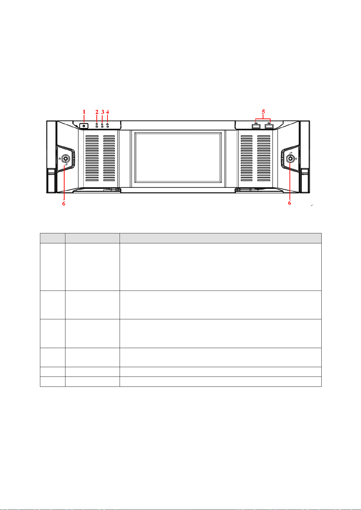
For the product of LCD, the front panel of NVR6000/NVR6064/NVR616-128-4K is shown as bel ow. See
Figure 2-1.
Figure 2-1
Please refer to the following sheet for front panel button information.
SN Name Function
1 Power button Press it once to turn on the device.
Press i t for a long time to turn off the device. (U
recommend).
Press power button for a long tim e or pull out the power c able may
2
Indicator light
3 Alarm indicator
light
4 Network
indicator light
5 USB port /
For general NVR6000/NVR6064/NVR616-128--4K series, the front panel is shown as in Figure 2-2.
The blue light becomes on after system booted up properly.
In the system HDD, there are device important configuration file,
The alarm indicator light becomes on once an alarm occurred. It
becomes on via the software detection. The alarm includes local
alarm, no disk and etc.
The blue networ k indicator lig ht is on after you connected the de vice
to the network.
12
Page 23
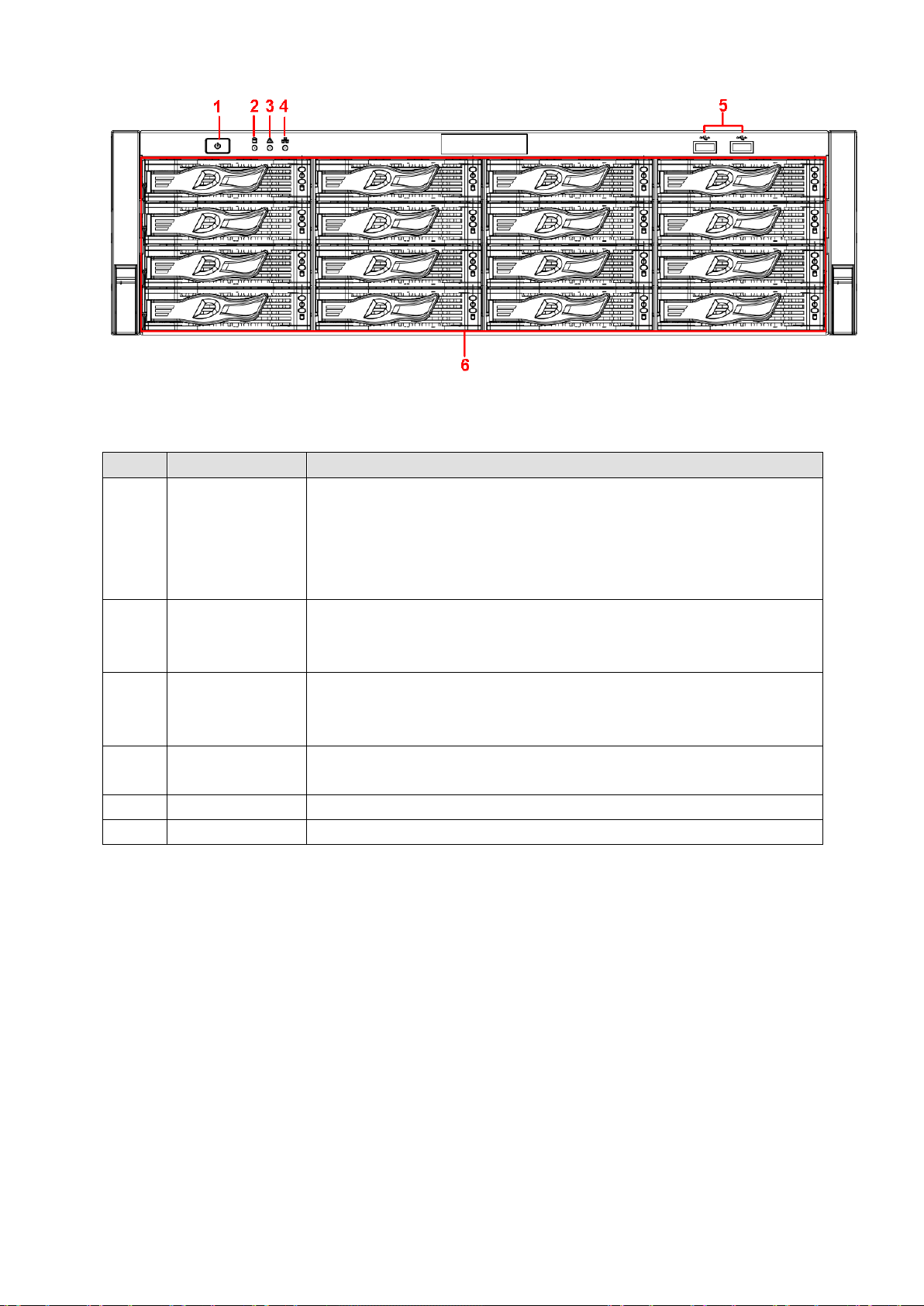
Figure 2-2
SN
Name
Function
sually we do not
System HDD
factory default configuration file, device initial boot up data.
alarm, no disk and etc.
indicator light
to the network.
5
USB port
/ 6 16 HDD slot
/
Please refer to the following sheet for detailed information.
1 Power button Press it once to turn on the device.
Press it for a long time to turn off the device (U
recommend).
Press power button for a long tim e or pull out the power c able may
result in device auto restart.
2
Indicator light
The blue light becomes on after system booted up properly.
In the system HDD, there are device important configuration file,
3 Alarm indicator
light
4 Network
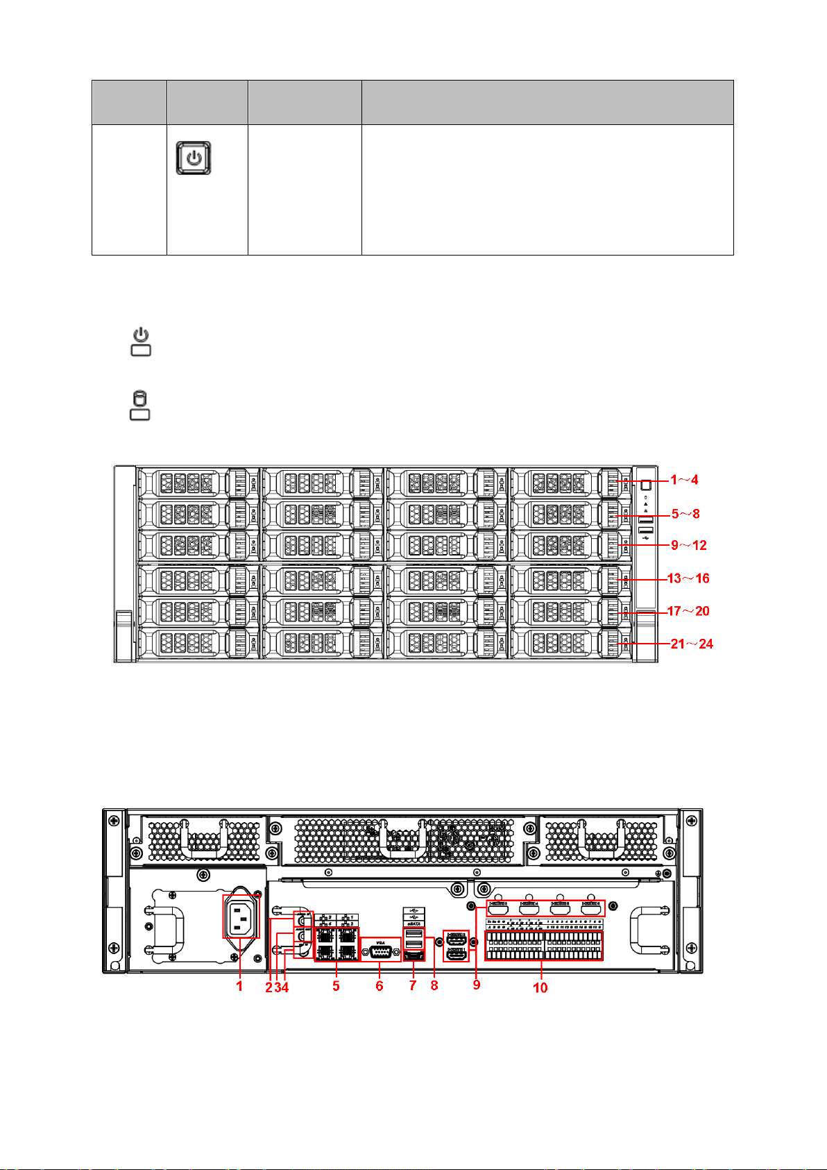
After you remo ve the front panel, you can see there ar e 16 HDDs . Fr om the l eft to the right and from the
top to the bottom, it ranges from 1~4, 5~8, 6~12, 13~16. See Figure 2-3.
You can see there are two indicator lights on the HDD bracket.
The power indicator light is at the top. The light is yellow after you connected the device to the power.
The read-write indicator light is at the bottom. The blue light flashes when system is reading or
writing the data.
The alarm indicator light becomes on once an alarm occurred. It
becomes on via the software detection. The alarm includes local
The blue networ k indicator lig ht is on after you connected the de vice
13
Page 24
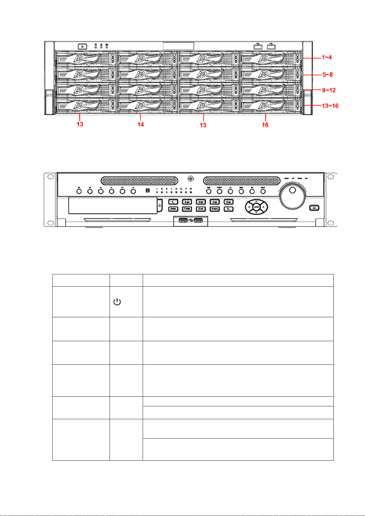
Figure 2-3
9 and
Input number
function: PTZ control and image color.
2.1.2 NVR608-4K Series
The NVR608-128-4K front panel is shown as in Figure 2-4.
Figure 2-4
Please refer to the following sheet for detailed information.
Name Icon Function
Power button
Number button
Record
more than 10
ESC
Assistant
0etc
REC
-/--
ESC
Fn
Power button, press this butt on for thre e seconds to b oot up or
shut down NVR.
Input Arabic number
Switch channel
Manually stop/start recording, working with direction keys
or numeral keys to select the recording channel.
If you want to input a number more than 10, please click this
button and then input.
Go to previous menu, or cancel current operation.
When playback, click it to restore real-time monitor mode.
One-window monitor mode, cli ck this butt on to displ ay assis tant
Backspace function: in numeral control or text control, press it for
1.5seconds to delete the previous character before the cursor.
14
Page 25

In motion det ec ti on set up, worki ng wit h Fn and di rec ti on keys to
h between numeral, English
character(small/capitalized) and etc.
English(Small/Capitalized),donation and etc.
Enable or disable tour.
down.
menu.
Confirm current operation
Go to menu
realize setup.
In text mode, click it to switc
In HDD managem ent interface, you can click it to s witch HDD
record information and other information (Menu prompt)
Realize other special functions.
Window switch
Shift
Up/
Down
Left/
Right
Slow play
Fast play
Mult
Click it to switch one-window/multiple-window.
In textbox, click this button to switch between numeral,
Activate current control, modify setup, and then move up and
Increase/decrease numeral.
Assistant function such as PTZ menu.
Shift current activated control, and then move left and right.
When playback, click these buttons to control playback bar.
Multiple slow play speeds or normal playback.
Various fast speeds and normal playback.
Play previous
Reverse/Pause
Play Next
Play/Pause
Enter
ENTER
In playback mode, playback the previous video.
In normal playback or pause mode, click this button to reverse
playback
In reverse playback, click this button to pause playback.
In playback mode, playback the next video
In normal playback click this button to pause playback.
In pause mode, click this button to resume playback.
In backward playback or pause mode, click this button to resume
normal playback.
In real-ti me moni tor mode, clic k this button to g o to the sear ch
Go to default button
15
Page 26

Shuttle(outer
backward.
Power indicator
Remote control
Status indicator
HDD abnormal
D, HDD error
light
ring)
In real-time monitor mode it works as left/right direction key.
Playback m ode, coun ter cloc kwise to for ward and cl ock wis e to
Jog(inner dial)
USB port
Channel indi cator
light
IR Receiver
light
indicator light
1-16
IR
POWER
ACT
Up/down direction key.
Playback mode, turn the inner dial to realized frame by frame
playback. (Only applies to some special versions.)
To connect USB storage device, USB mouse and etc.
It becomes on when system is recording.
It is to receive the signal from the remote control.
Power indicator light.
Remote control indicator light.
light
STATUS
HDD
indicator light
If there is Fn indicator light, current status indicator light is null.
The indicator light is on when there is no HD
occurred or HDD capacity is below specified threshold value.
The NVR608-32-4K front panel is shown as in Figure 2-5.
Figure 2-5
Please refer to the following sheet for front panel button information.
Icon Name Function
STATUS Status indicator light The blue light is on when the device is working
properly.
HDD HDD status indicator
The blue light is on when the HDD is malfunction.
16
Page 27
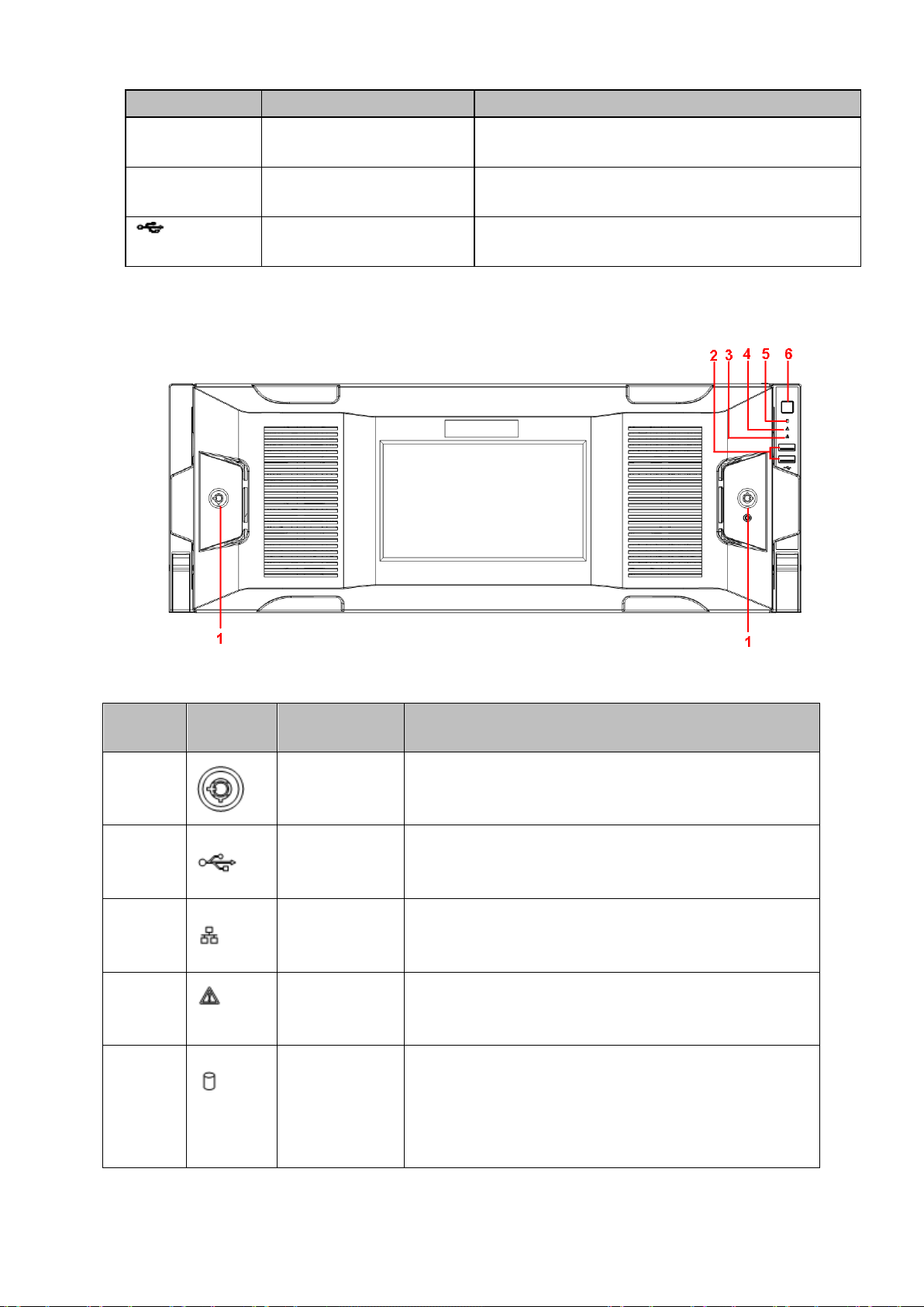
Icon Name Function
rk status indicator
light
abnormal.
Front panel
alarm includes local alarm, no disk and etc.
System HDD
ion file, factory default configuration file,
device initial boot up data.
NET Netwo
POWER Power status indicator light The blue light is on when the power connec tion is
USB2.0 port Connect to peripheral USB 2.0 storage device,
The blue light is on when the network connection is
OK.
mouse, burner and etc.
2.1.3 NVR724-256 Series
For the product of the LCD screen, the front panel is shown as in Figure 2-6.
SN Icon Name Function
1
2
3
4
5
lock
USB port /
Network
indicator light
Alarm indicator
light
Indicator light
/
The networ k indicator light is blue and it flashes when
you connect the device to the network.
The alarm indicator light becomes on once an alarm
occurred. It becomes on via the software detection. The
The bl ue light becomes on when system i s reading or
writing the system HDD.
In the system HDD, there are device important
configurat
Figure 2-6
17
Page 28
SN Icon Name Function
6
After you remo ve the front panel, you can see there ar e 24 H DDs . Fr om the left to the right and from the
top to the bottom, it ranges from 1~4, 5~8, 9~12, 13~16, 17~20, 21~24. See Figure 2-7.
You can see there are two indicator lights on the HDD bracket.
: The power i ndic ator light is at the top. T he l i ght is yellow after you connec ted the de vice to th e
power.
: T he read-write indicator light i s at the bottom. The blue light fl ashes w hen system is readi ng or
writing the data.
Power button
Press it once to turn on the device.
Press i t for a long time to turn off the device ( Usually
we do not recommend).
Press power button for a long time or pull out the power
cable may result in device auto restart.
Figure 2-7
2.2 Rear Panel
2.2.1 NVR6000 Series
The general series rear panel of NVR6000/NVR6064 is shown as in Figure 2-8.
Figure 2-8
The redundant power series rear panel of NVR6000/NVR6064 is shown as in Figure 2-9.
18
Page 29
SN
Function
SN
Function
1
Power socket
2
Audio Input
3
Audio output
4
Bidirectional talk input
9
HDMI port
10
Alarm input/alarm output/RS485 port.
Figure 2-9
Please refer to the following sheet for rear detailed information.
5 Network port 6 Video VGA output
7 eSATA port 8 USB port
Important
Right now, system does not support audio input port. System supports HDMI1/HDMI2 port by
default. You need to purc hase HDMI interface board if you want to use HDMI3-HDMI6 port.
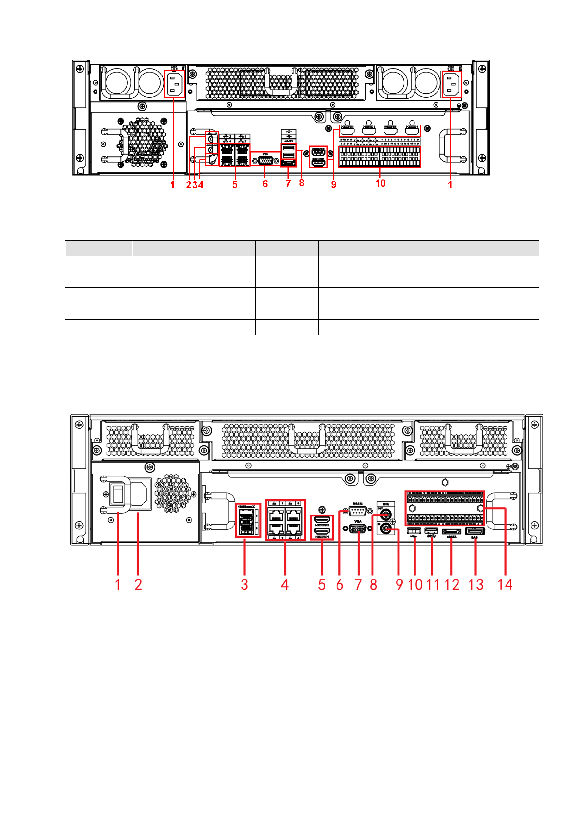
2.2.2 NVR616-128-4K Series
The general series rear panel of NVR616-128-4K is shown as in Figure 2-10.
The redundant power series rear panel of NVR616-128-4K is shown as in Figure 2-11.
Figure 2-10
19
Page 30
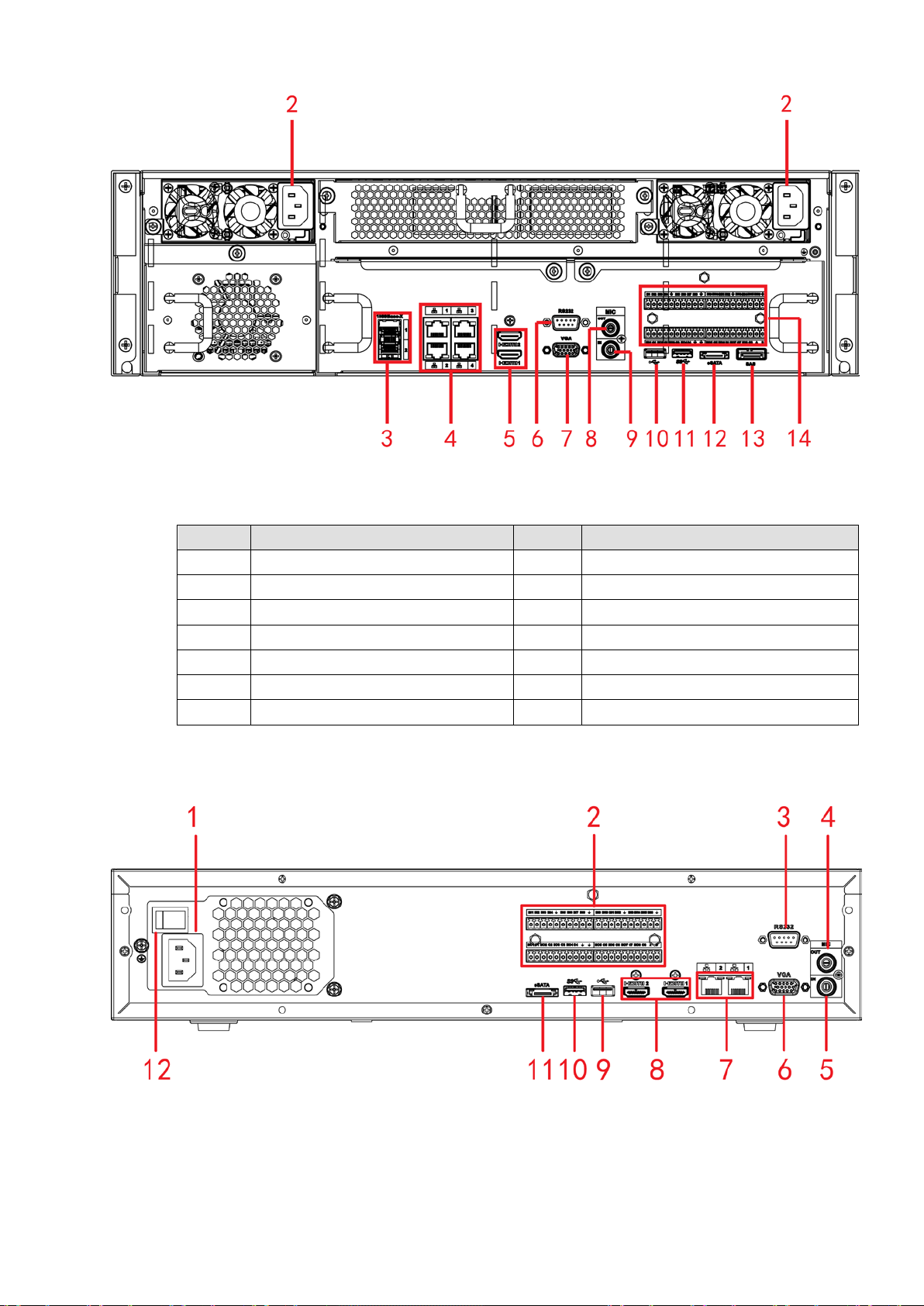
Figure 2-11
SN
Name
SN
Name
1
Power on-off butto n
2
Power socket
3
1000M fiber port
4
Network port
5
HDMI port
6
RS232 port
7
Video VGA output
8
Audio output
9
Audio input
10
USB2.0 port
Please refer to the following sheet for rear detailed information.
11 USB3.0 port 12 eSATA port
13 SAS extension port 14 Alarm input/output/RS485 port
2.2.3 NVR608-4K Series
The NVR608-32-4K series rear panel is shown as in Figure 2-12.
The NVR608-64-4K/NVR608-128-4K general series rear panel is shown as in Figure 2-13.
Figure 2-12
20
Page 31

Figure 2-13
1
Power socket
2
Alarm input/alarm output/RS485 port.
5
Audio input
6
VGA port
7
Network port
8
HDMI port
9
USB 2.0 port
10
USB 3.0 port
The NVR608-64-4K/NVR608-128-4K redundant power series rear panel is shown as in Figure 2-14.
Figure 2-14
Please refer to the following sheet for detailed information.
SN Function SN Function
2 RS232 port 4 Audio output
11 eSATA port
2.2.4 NVR724-256 Series
The general rear panel is shown as in Figure 2-15.
21
Page 32

Figure 2-15
The redundant power series rear panel is shown as in Figure 2-16.
Figure 2-16
Please refer to the following sheet for detailed information.
SN Name SN Name
1 Alarm input/alarm output 2
HDMI port(Reserved port. Right now
system does not support HD decode
card.)
3 Power port 4 HDMI port
5 eSATA port 6 USB port
22
Page 33

SN Name SN Name
7 SAS port 8 Video VGA output
9 Network port 10 RS485 port
11 RS232 port 12 Audio input port
13 Audio output port
2.3 Alarm Connection
Please refer to the following sheet for alarm input and output connection.
There are two alarm input types for you to select: normal open (NO) and normal close (NC).
1. Alarm input
a. Please make sure alarm input mode is grounding alarm input.
b. Grounding signal is needed for alarm input.
c. Alarm input needs the low level voltage signal.
d. Alarm input mode can be either NC (normal Open) or NO (Normal Close)
e. When you are connecting two NVRs or you are connecting one NVR and one other device, please use
a relay to separate them.
2. Alarm output
The al arm output por t shoul d not be connec ted to high pow er load direc tly (It shal l be les s than 1A) to
avoid high current which may result in relay damage. Please use the co contactor to realize the
connection between the alarm output port and the load.
3. Please make sure the front-end device has soundly earthed.
Improper grounding may result in chip damage.
2.3.1 Alarm input and output details
2.3.1.1 NVR6000/NVR616-128-4K Series
You can refer to the following sheet for alarm input and output information. See Figure 2-17.
Figure 2-17
Icon Note
23
Page 34

1,2,3,4,5,6,
12,13,14,15,16
7-ON C,8-ON C
G
GND cable.
guarantee the signal quality.
cable.
GND cable.
guarantee the signal quality.
7,8, 9,10,11,
ALARM 1 to ALARM 16. The alarm becomes active in low voltage.
1-ON C,2-ON C,
3-ON C,4-ON C,
5-ON C,6-ON C,
A/B The A/B cable to control the RS485 devices. It is to connect to
Tx and Rx RS232 port. Tx is the data out put c abl e an d the R x is the d ata i nput
Eight groups of normal open activation output (on/off button)
control devices suc h as PT Z dom e cam era. 120Ω should be parallel
connected between A, B lines on the far end to reduce reflection and
2.3.1.2 NVR608--4K Series
You can refer to the following sheet for alarm input and output information. See Figure 2-18.
Figure 2-18
Icon Note
1,2,3,4,5,6,
7,8, 9,10,11,
12,13,14,15,16
1-ON C,2-ON C,
3-ON C,4-ON C,
5-ON C,6-ON C,
7-ON C,8-ON C
A/B The A/B cable to control the RS485 devices. It is to connect to
ALARM 1 to ALARM 16. The alarm becomes active in low voltage.
Eight groups of normal open activation output (on/off button)
control devices suc h as PT Z dom e cam era. 120Ω should be parallel
connected between A, B lines on the far end to reduce reflection and
24
Page 35

2.3.1.3 NVR724 Series
Icon
Note
C4
Four groups of normal open activation output (on/off
button)
You can refer to the following sheet for alarm input and output information. See Figure 2-19.
Figure 2-19
1~4
NO1 C1,NO2 C2,NO3 C3,NO4
ALARM 1 to ALAR M 4. The alar m becomes active in low
voltage.
GND
2.3.2 Alarm input and output port
Please refer to the following sheet for more information.
Grounding alarm inputs. Normal open or Normal close type)
Please parallel connect COM end and GND en d of the alarm detector (Provide external power to the
al ar m d e tector ) .
Please parallel connect the Ground of the NVR and the ground of the alarm detector.
Please connect the NC port of the alarm sensor to the NVR alarm input(ALARM)
Use the same ground with that of NVR if you use external power to the alarm device.
2.3.3 Alarm Output Port
Provide power to peripheral alarm device.
Figure 2-20
25
Page 36

To avoid overloading, please read the f ol lo win g relay parameters sheet carefully.
JRC-27F
touch
Rated switch capa city
30VDC 2A, 125VAC 1A
Maximum switch currency
1A
polarity
Between touch and winding
1000VAC 1minute
polarity
time
Mechanical
50×106
(3Hz)
Electrical
200×103
(0.5Hz)
Left click
When you have selected one menu item, left click mouse to view menu content.
Modify checkbox or motion detection status.
Click combo box to pop up dropdown list
RS485 A/B cable is for the A/B cable of the PTZ decoder.
2.3.4 Alarm relay specifications
Model:
Material of the
Rating
(Resistance
Load)
Insulation Between touches with same
Surge voltage
Length of open
Length of close
time
Longevity
Temperature -40 ℃ ~ + 7 0 ℃
Silver
Maximum switch po w er 125VA 160W
Maximum switch voltage 250VAC, 220VDC
Between touches with different
polarity
Between touches with same
3ms max
3ms max
1000VAC 1minute
1000VAC 1minute
1500V (10×160us)
MIN
MIN
2.4 Mouse Operation
Please refer to the following sheet for mouse operation instruction.
mouse
26
Page 37

In input bo x, you can s el ect i nput m ethods . Left c li c k the corr es ponding butt on
previous numeral.
ble left
mode.
Right click
mouse
In real-time monitor mode, pops up shortcut menu.
Exit current menu without saving the modification.
In numeral input box: Increase or decrease numeral value.
Page up or page down
Select privacy mask zone.
2.5 Mouse Control
Left click
In real-time monitor mode, you can go to the main menu.
When you have selected one menu item, left click mouse to view menu content.
Implement the control operation.
Modify checkbox or motion detection status.
on the panel you c an inp ut num er al /Engli sh c har acter (s m all/c apitalized). Her e
← stands for backspace button. _ stands for space button.
In Engli sh input mode: _stands for input a backspace icon and ← stands for
deleting the previous character.
In numeral input mode: _ stands for clear and ← stands for deleting the
Dou
click mouse
Press middle
button
Move mouse Select current control or move control
Drag mouse Select motion detection zone
Implement special control operation such as double click one item in the file list
to playback the video.
In multiple-window mode, double left click one channel to view in full-window.
Double left click current video again to go back to previous multiple-window
Switch the items in the check box.
System pops up password input dialogue box if you have not logged in.
mouse
Click combo box to pop up drop down list
27
Page 38

In input bo x, you can s el ect i nput m ethods . Left c li c k the corr es ponding butt on
Double left
to playback the video.
mode.
on the panel you c an inp ut num er al /Engli sh c har acter (s m all/c apitalized). Her e
← stands for backspace button. _ stands for space button.
In Engli sh input mode: _stands for input a backspace icon and ← stands for
deleting the previous character.
In numeral input mode: _ stands for clear and ← stands for deleting the
previous numeral.
When input special sign, you can click corresponding numeral in the front panel
to input. F or exampl e, click num eral 1 you can input“/” , or you c an cli ck the
numeral in the on-screen keyboard directly.
click mouse
Implement special control operation such as double click one item in the file list
In multiple-window mode, double left click one channel to view in full-window.
Double left click current video again to go back to previous multiple-window
28
Page 39

Right click
mouse
t selected
In numeral input box: Increase or decrease numeral value.
Page up or page down
Select privacy mask zone.
In real-tim e monitor mode, pops up shortcut menu: one-window, four-window,
nine-window and si xteen-window, Pan/Til t/Zoom, col or setting, s earch, r ecord,
alarm input, alarm output, main menu.
Among which, Pan/Tilt/Zoom and color setting applies for curren
channel.
If you are in multiple-window mode, system automatically switches to the
corresponding channel.
Exit current menu without saving the modification.
Press middle
button
Move mouse Select current control or move control
Drag mouse Select motion detection zone
Switch the items in the check box.
29
Page 40

3 Loc al B a sic Operation
3.1 Boot up and Shutdown
3.1.1 Boot up
Caution
Before the boot up, please make sure:
For device security, please connect the NVR to the power adapter first and then connect the
device to the power socket.
The rated input voltage matches the device power on-off button. Please make sure the power
wire connection is OK. Then click the power on-off button.
Always use the stable current, if necessary UPS is a best alternative measure.
Please follow the steps listed below to boot up the device.
Connect the device to the monitor and then connect a mouse.
Connect power cable.
Click the power button at the front or rear panel and then boot up the device. After device booted up,
the system is in multiple-channel display mode by default.
3.1.2 Shutdown
Note
When you see corres ponding dialogue bo x “System is shutting down…” Do not c lick power on-off
button directly.
Do not unplug the power c abl e or clic k power on-off button to s hutdown de vice di rec tl y when device
is running (especially when it is recording.)
There are three ways for you to log out.
a) Main menu (RECOMMENDED)
From Main Menu->Shutdown, select shutdown from dropdown list.
Click OK button, you can see device shuts down.
b) From po w er on -off button on the front panel or remote control
Press the power on-off button on the NVR front panel or remote control for more than 3 seconds to
shutdown the device.
c) Fr om power on -off button on the rear panel.
3.2 Startup Wizard
After device successfully booted up, it goes to startup wizard.
Click Cancel/Next button, you can see system goes to login interface.
Tips
Check the box Startup button here, system goes to startup wizard again when it boots up the next time.
Cancel the Startup button, system goes to the login interface directly when it boots up the next time.
30
Page 41

Figure 3-1
Click Cancel button or Next Step button, system goes to login interface. See Figure 3-2.
System consists of four accounts:
Username: admin. Password: admin. (administrator, local and network)
Username: 888888. Password: 888888. (administrator, local only)
Username: 666666. Password: 666666(Lower authority user who can only monitor, playback,
backup and etc.)
Username: default. Password: default (hidden user). Hidden user “default” is for system interior use
only and can not be deleted. When there is no login user, hidden user “default” automatically login.
You can set some rights such as monitor for this user so that you can view some channel view
without login.
Figure 3-2
Note:
For security reason, please modify password after you first login.
Within 30 minutes, three times login failure will result in system alarm and five times login failure will result
in account lock!
Click OK button, you can go to General interface. See Figure 3-3.
For detailed information, please refer to chapter 3.13.1.
31
Page 42

Figure 3-3
Clic k Next button, you can go to network interface. See Figure 3-4.
For detailed information, please refer to chapter 3.11.
Figure 3-4
Click Next button, you can go to remote device interface. See Figure 3-5.
For detailed information, please refer to chapter 3.4.
32
Page 43

Figure 3-5
Click Next button, you can go to RAID interface. See Figure 3-6.
For detailed information, please refer to chapter 3.12.4.
Figure 3-6
Click Next button, you can go to Schedule interface. See Figure 3-7.
33
Page 44

For detailed information, please refer to chapter 3.7.2.
Figure 3-7
Clic k Fi nish button, system pops up a di alogue bo x. Cl i ck the OK b utton, the startup wi zard i s c om pl ete.
See Figure 3-8.
Figure 3-8
3.3 Navigation Bar
You need to go to the Main menu->Setting->System->General to enable navigation bar function;
otherwise you can not see the following interface.
The navigation bar is shown as below. See Fig ure 3-9.
Figure 3-9
34
Page 45

3.3.1 Main Menu
Click button to go to the main menu interface.
3.3.2 Dual-screen operation
Important
This function is for some series only.
Click
navigation bar for screen 2.
Click any screen split mode; HDMI2 screen can display corresponding screens. Now you can control two
screens. See Figure 3-11.
Note
Screen 2 function is null if tour is in process. Please disable tour function first,
Right now, the screen 2 operation can only be realized on the navigation bard. The operations on the
right-click menu are for screen 1 only.
to select screen 2, you can view an interface shown as below. See Figure 3-10. It is a
Figure 3-10
Figure 3-11
3.3.3 Output Scr ee n
Select corresponding window-split mode and output channels.
3.3.4 Tour
Click button to enable tour, the icon becomes , you can see the tour is in process.
3.3.5 PTZ
Click , system goes to the PTZ control interface. Please refer to chapter 3.6.2.
3.3.6 Color
Click button , system goes to the color interface. Please refer to chapter 3.4.3.
Please make sure system is in one-channel mode.
3.3.7 Search
Click button
, system goes to search interface. Please refer to chapter 3.8.2
3.3.8 Alarm Status
35
Page 46

Click button , system goes to alarm status interface. It is to view device status and channel status.
Please refer to chapter 3.14.1.5.
3.3.9 Channel Info
Click button , system goes to the channel information setup interface. It is to view information of the
corresponding channel. See Figure 3-12.
Figure 3-12
3.3.10 Remote Device
Click , system goes to the remote device interface. Please refer to chapter 3.4.
3.3.11 Network
Click , system goes to the network interface. It is to set network IP address, default gateway and etc.
Please refer to chapter 3.11.
3.3.12 HDD Manager
Click , system goes to the HDD manager interface. It is to view and manage HDD information.
Please refer to chapter 3.12.1.
3.3.13 USB Manager
36
Page 47

Click , system goes to the USB Manager interface. See Figure 3-13. It is to view USB information,
backup and update. Please refer to chapter 3.9.1 file backup, chapter 3.9.3 backup log, chapter3.9.2
import/export, and chapter 3.14.4 upgrade for detailed information.
Figure 3-13
3.3.14 System Status
Click , you can go t o th e fol low ing i nter face. See Fi gur e 3-14. Her e you c an view hos t i nform ati on,
RAID information, HDD information, HDD usage rate, fan speed, CPU usage, CPU temperature, memory
usage, power information and etc.
The following interface for reference only.
Figure 3-14
37
Page 48

3.3.15 Device Tree
Click , you can go to the following interface. See Figure 3-15.
You can view channel list and device list.
Figure 3-15
3.4 Remote Device
3.4.1 Remote Device Connection
From Mani menu->Setting->Remote->Remote or right click mouse on the preview interface and then
select remote device item, you can see the following interface. See Figure 3-16.
38
Page 49

Figure 3-16
Click Device search button, you can view the searched IP addresses at the top pane of the interface.
Double click an IP address or check one IP address and then click Add but ton, you can add current
device to the bottom pane of the interface. System supports batch add function.
Clic k Manual Add button, you can add a device di rectly. Here you can set T CP/UPD/auto connection
mode. The default setup is TCP. See Figure 3-17.
Important
Please note the manual add function is for Dahua, Panasonic, Sony, Dynacolor, Samsung, AXIS, Arecont,
ONVIF and Custom. When the type is the custom, you can just input URL address, user name and
password connect to the network camera without considering network camera manufacture. Please
contact your network camera manufacturer for the URL address.
39
Page 50

Figure 3-17
3.4.2 Short-Cut Menu
In the preview inter fac e, for t he c hann el of no IPC conn ec ti on, you can c li c k the ic on “+” in t he centr e of
the interface to quickly go to the Remote Device interface. See Figure 3-18.
Figure 3-18
3.4.3 Image
From main menu->Setting->Camera->Image, you can see the image interface is shown as below.
See Figure 3-19.
Channel: Select a channel fr om t he dr o pd o wn lis t .
Config file: The options includes: day/night/general/switch by period. Once the mod e is switch by
period, you can set sunset and sunrise time.
Saturation: It is to adjust monitor window saturation. The value ranges from 0 to 100. The default
value is 50. The larger the number, the strong the color is. This value has no effect on the general
brightness of the whole video. The video color may become too strong if the value is too high. For
40
Page 51

the grey part of the video, the distortion may occur if the white balance is not accurate. Please note
the video may not be attractive if the value is too low. The recommended value ranges from 40 to 60.
Bright ness: It is to adjust monitor window br ight. The value ranges from 0 to 100. The default value is
50. The larger the number is, the bright the video is. When you input the value here, the bright
secti on an d th e dark sec tio n o f t h e vi d e o wi l l be a dj u s t e d ac c ordi n gly. Y o u c an us e t hi s fu nctio n
when the whole video is too dark or too bright. Please note the video may become hazy if the value
is too high. The recommended value ranges from 40 to 60.
Contrast: It is to adjust monitor window contrast. The value ranges from 0 to 100. The default value
is 50. The larger the number is, the hi gher the contrast is. You can use this function when the whole
video bright is OK but the contrast is not proper. Please note the vid eo may become hazy if the value
is too low. If this value is too high, the dark section may lack brightness while the bright section may
over exposure .The recommended value ranges from 40 to 60.
Auto Iris: It is for the device of the auto lens. You can check the box before ON to enable this
function. The auto iris may change if the light becomes diffe rent. When you disable this functio n, the
iris is at the max. System does not add the auto iris fun ction in the exposure control. This function is
on by default.
Mirror: It is to switch video up and bottom limit. This function is disabled by default.
Flip: It is to switch video left and right limit. This function is disabled by default.
3D NR : It is to p r ocess mul tipl e-frame (At l ea st t w o frames ) . S ys tem uses t he i n f ormation b e twee n
these two frames to realize noise reduction function.
BLC: It includes several options: BLC/WDR/HLC/OFF.
BLC: There are two modes: def aul t/customize. For the default mode, the device auto exposures
according to the environments situation so that the darkest area of the video is clearer. For the
customized mode, you can select a rectangle zone to enhance its brightness to the proper lev el.
WDR: For the WDR scene, this function can lower the high bright section and enhance the
brightness of the low bright section. So that you can view these two sections clearly at the same time.
The value ranges from 1 to 100. When you switch the camera from no-WDR mode to the WDR mode,
system may lose sev eral seconds record video.
HLC: After you enabled HLC function, the device can lower the brightness of the brightest section
according to the HLC contro l level. It can reduce the area of the halo and lower the brightness of the
whole video.
OFF: It is to disable the BLC function. Please note this function is disabled by default.
Profi le: It is to set the white balance mode. It has effect on the general hue of the video. This function
is on by default. You can select the different scene mode such as auto, sunny, cloudy, home, office,
night, disable and etc to adjust the video to the best quality.
Auto: The auto white balance is on. System can auto compensate the color temperature to make
sure th e vide c olor i s prop er.
Sunny: The threshold of the white balance is in the sunny mode.
Night: The threshold of the white balance is in the night mode.
Customized: You can set the gain of the red/blue channel. The value reneges from 0 to 100.
Day/night. It is to set device color and the B/W mode switch. The default setup is auto.
Color : D e vice ou t p uts t he color video .
Auto: Device auto select to output the color or the B/W video according to the device feature (The
general bright of the video or th er e i s I R li g h t or not . )
B/W: The device outputs the black and white video.
41
Page 52

Sensor: It is to set when there is peripheral connected IR light. Please note some non-IR ser i e s
product support sensor input function.
Figure 3-19
3.4.4 Channel Name
From main menu->Setting->Camera->Channel name, you can see an interface shown as in Figure 3-20.
It is to modify channel name. It max supports 31-character.
Please note you can only modify the channel name of the connected network camera.
42
Page 53

Figure 3-20
3.4.5 Upgrade
Important
System max supports to upgrade 8 network cameras at the same time.
It is to update the network camera.
From m ain menu->Setting->Camera->Remote->Upgrade, the interface is s hown as below. See Figure
3-21.
Clic k Browse button and then select the upgrade file. T hen select a channel (or you can select device
type filter to select several devices at the same time.)
Click Begin button to upgrade. You can see the corresponding dialogue once the upgrade is finish.
43
Page 54

Figure 3-21
3.5 Preview
After device booted up, the system is in multiple -channel display mode. See Figure 3-22.Please note the
displayed window amount may vary. The following figure is for reference only. Please refer to chapter 1.3
Specifications for the window-amount your product supported.
Figure 3-22
3.5.1 Preview
If you want to change system date and time, you can refer to general settings (Main
44
Page 55

Menu->Setting->System->General). If you want to modify the channel name, please refer to the
this icon when it is
recording.
up this icon
this icon when motion
detect alarm occurs.
System exceeds
1 2 3 4 5 6
display setti ngs (Main Menu->Camera->CAM name)
Please refer to the following sheet for detailed information.
Current channel pops up
1
2
5
Tips
Preview drag: If you want to change position of channel 1 and channel 2 when you are
Current channel pops up
decoded channel
amount.
previewing, you can left click mouse in the channe l 1 and then drag to chan nel 2, release mouse
you can switch channe l 1 and channel 2 positions.
3
4
Current channel pops
when video loss alarm occurs.
Current channel pops up this icon
when it is in monitor lock status.
3.5.2 Preview control int erf ac e
Move you mouse to the top centre of the video of current channel, you can see system pops up the
pr e view con tr ol int erfac e . S e e Figure 3-23. If you r mo use s t a ys i n this are a f o r mor e th a n 6 sec o n ds
and has no operation, the control bar automatically hides.
Figure 3-23
1) Realtime playback
It is to playback the previous 5-60 minutes record of current channe l.
Please go to the Main menu->Setting->->System->General to set real-time playback time.
System may pop up a dialogue box if there is no such record in current channel.
2) D igit al zoom
It is to zoom in specified zone of current channel. It supports zoom in function of multiple-channel.
Click button
There are two ways for you to zoom in.
Drag the mouse to select a zone, you can view an interface show as Figure 3-24.
, the button is shown as .
45
Page 56

Figure 3-24
Put the middle button at the centre of the zone you want to zoom in, and move the mouse, you
can view an interface shown as in Figure 3-25.
Figure 3-25
Right click mouse to cancel zoom and go back to the original interface.
3) Manual record function
It is to backup the video of current channel to the USB device. System can not backup the video of
multiple-c hannel at the same time.
Click button
file on the flash disk.
4) Manual Snapshot
Click
the Search interface (chapter 3.8) to view.
5) Bidirectional talk
If the connected front-end device supports bidirectional talk function, you can click this button. Click
button
bi di rection al t alk bu t to ns of di gi t al cha n n el b ecom es n ul l to o.
Click
channels become as
6) Remote device
Shortcut menu. Click it to go to the remote device interface to add/delete remote device or view its
corresponding infor mation. Please refer to chapter3.4.2 for detailed information.
agai n, you ca n cancel bidirec tion al talk a nd the bidirecti onal tal k butt ons of other di gital
, system begins recording. Click it again, system stops recoridng. Y ou can find the record
to snapshot 1-5 ti m es . The snapshot fi l e is saved on the USB de vice or H DD. You can go to
to start bidirectional talk function the icon now is shown as . Now the rest
.
3.5.3 Right Click Men u
46
Page 57

After you logged in the de vice, ri ght cli ck mouse, you can s ee the short cut m enu. Please see Figure
3-26.
Window split mode: You can select window amount and then select channels.
PTZ: Click it to go to PTZ interface.
Auto focus: It is to set auto focus function. Please make sure the connected network camera
supports this function.
Image: Set video corresponding information.
Search: Click it to go to Search interface to search and playback a record file.
Record control: Enable/disable record channel.
Alarm output: It is to set alarm output mode.
Remote: Search and add a remote device.
Alarm output: Generate alarm output signal manually.
Main menu: Go to system main menu interface.
Tips:
Right click mouse to go back to the previous interface.
Figure 3-26
3.5.4 Preview Display Effect Setup
3.5.4.1 Display From Main Menu->Setting->System->Display, you can go to the following interface. See Figure 3-27. Here you can set menu and video preview effect. A ll you operation here does not affect the record file and playback effect.
47
Page 58

Figure 3-27
Now you can set corresponding information.
Time display: You can select to display time or not when system is playback.
Channel display: You can select to channel name or not when system is playback.
Image enhance: Check the box; you can optimize the margin of the preview video.
IVS rule: Check the box to enable IVS function. System can display IVS rule on the preview video.
Screen mode: It is for dual-screen operation. Please select from the dropdown list according to your
actual situation. Click Apply button, system needs to restart to activate new setup. For example,
32+4 means for VGA, system max supports 32-window split and for HDMI2, system max supports
4-window split.
Screen enable: Check the box here to enable the screen. In this way, it can display the video.
Screen No. Select the corresponding screen from the dropdown list and then set resolution.
Resolution: There are four options: 1920×1080, 1280×1024, 1280×720, and 1024×768. The VGA default
resolution is 1280×1024; HDMI default resolution is 1920×1080. Please note the system needs to
reboot to activate current setup.
Click OK button to save current setup.
3.5.4.2 Preview Tour Parameters Set preview display mode, channel display sequence and tour setup. Set preview display mode: On the preview interface, right click mouse, you can view right-click menu.
Now you can select preview window amount and channel.
Set channel display mode: On the preview interface, if you want to change channel 1 and channel 16
positi on, please r ight clic k channel 1 video wi ndow and the n drag to the chan nel 16 video wind ow,
release button, you can change channel 1 and channel 16 position.
Tour setup: Here you can s et pre view wi nd ow channel dis pl ay mode an d i nterval. Pleas e f oll ow the
steps listed below.
From Main menu->Setting->System->Display->Tour, you can see an interface shown as in Figure 3-28.
Here you can set tour parameter.
48
Page 59

Screen No.: Please select screen from the dropdown list.
Video detect: It is to set video detect tour. System supports 1/8-window tour.
Alarm: It is to set alarm tour . System supports 1/8-window tour.
Enable tour: Check the box here to enable tour function.
Interval: Input proper interval value here. The value ranges from 1-120 seconds.
Window split: It is to set window split mode.
Figure 3-28
Tips
On the navigation bar, click
Click Save button to save current setup.
/ to enable/disable tour.
3.6 PTZ
Note:
Before you control the PTZ, please make sure the PTZ decoder and the NVR network
connection is OK and the corresponding settings are right.
3.6.1 PTZ Settings
Cable Connection
Pl ease fol low the proc e d ur es b elow to g o o n ca ble con nec ti o n
Connect the dome RS485 port to NVR RS485 port.
Connect dome video output cable to NVR video input port.
Connect power adapter to the dome.
In the main menu, from Setting->System->PTZ, you can see an interface is shown as in Figure 3-29.
Here you can set the following items:
Channel: Select the current camera channel.
49
Page 60

PTZ type: There are two types: local/remote. Please select local mode if you are connect RS485
cable to connect to the Speed dome (PTZ). Please select remote mode if you are connecting to the
network PTZ camera.
Pro to c ol : Sel ec t c or r espon din g PT Z prot oc ol (suc h as P E L COD)
Address: Default address is 1.
Baud rate: Select corresponding baud rate. Default value is 9600.
Data bit: Select corresponding data bits. Default value is 8.
Sto p bit : Sel ec t c orres p on din g st o p bits . D ef a ult value i s 1 .
Parity: There are three options: odd/even/none. Default setup is none.
Figure 3-29
If you are connecting to network PTZ, the PTZ type shall be remote. See Figure 3-30.
50
Page 61

Figure 3-30
3.6.2 PTZ Control
After completing all the setting please click save button. Right click mouse (click “Fn” Button in the
front panel or click “Fn” key in the remote control). The interface is shown as in Figure 3-31. Please
note you can only go to the PTZ control interface when you are in 1-window display mode.
Figure 3-31
The PTZ setup is shown as in See Figure 3-32.
Please note the commend name is grey once device does not support this function.
The PTZ operation is only valid in one-window mode.
Here you can control PTZ direction, speed, zoom, focus, iris, preset, tour, scan, pattern aux function, light
51
Page 62

and wiper, rotation and etc.
key
key
key
key
Speed is to control PTZ movement speed. The value ranges from 1 to 8.The speed 8 is faster than speed
1. You can use the remote control to click the small keyboard to set.
You can click
and of the zoom, focus and iris to zoom in/out, definition and brightness.
The PTZ rotation supports 8 directions. If you are using direction buttons on the front panel, there are only
four directions: up/down/left/right.
Figure 3-32
In the middl e of the eight direction arr ows, there is a 3D intelligent pos itioning key. See Figure 3-33.
Please make sure your protocol supports this function and you need to use mouse to control.
Clic k this key, system go es back to the s ingle screen m ode. Drag the mouse in the screen to adjust
section size. The dragged zone supports 4X to 16X speeds. It can realize PTZ automatically. The smaller
zone you dragged, the higher the speed.
Name Function
Zoom
Focus
Iris
In Figure 3-32, cl ic k
Figure 3-34.
Figure 3-33
function Shortcut
Near
Near
│
close
Function
function Shortcut
Far
Far ►
Open
│
to open the menu, you can set preset, tour, pattern, scan and etc. See
52
Page 63

Icon
Function
Icon
Function
button
Figure 3-34
Please refer to the following sheet for detailed information.
Please note the above interface may vary due to different protocols. The button is grey and can not
be selected once the current function is null.
Right click mouse or click the ESC button at the front panel to go back to the Figure 3-32.
Preset Flip
Tour Reset
Pattern Aux
Scan Aux on-off
Rotate Go to menu
3.6.2.1 PTZ Function Setup
Click
Preset Setup
, you can go to the following interface to set preset, tour, pattern, and scan. See Figure 3-35.
Figure 3-35
53
Page 64

In Figure 3-35, click preset button and use eight direction arrows to adjust camera to the proper position.
The interface is shown as in Figure 3-36.
Click Set button and then input preset number.
Click Set button to save current preset.
Figure 3-36
Tour Setup
In Figure 3-35, click tour button.
Input tour value and preset No. Click A dd preset button to add current preset to the tour. See Figure 3-37.
Tips
Repeat the above steps to add more presets to the tour. Click Del preset button to remove it from the tour .
Please note some protocols do not support delete preset function.
Figure 3-37
Pattern Setup
In Figure 3-35, click Pattern button and input pattern number.
Click Begin button to start direction operation. Or you can go back to Figure 3-32 to operate
zoom/focus/iris/direction operation.
In Figure 3-35, click End button.
54
Page 65

Figure 3-38
Scan Setup
In Figure 3-35, click Scan button.
Use direction buttons to set camera left limit and then click Left button.
Use direction buttons to set camera right limit and then click Right button. Now the scan setup process is
complete.
Figure 3-39
3.6.2.2 Call PTZ Function
Call Preset
In Figure 3-34, input preset value and then click
Call Pattern
In Figure 3-34, input pattern value and then click
call.
Call Tour
to call a preset. Click again to stop call.
to call a pattern. Click again to stop
55
Page 66

In Figure 3-34, input tour value and then click to c al l a tou r . Cl ick ag ain to stop call.
Call Scan
In Figure 3-34, input Scan value and then click
Rotate
In Figure 3-34, click
System supports preset, tour, pattern, scan, rota t e, li ght an d etc f unc tio n.
Note:
Preset, tour and pattern all need the value to be the control parameters. You can define it as you
require.
You need to refer to your camera user’s manual for Aux definition. In some cases, it can be used for
special process.
Aux
Click
number is corresponding to the aux on-off button of the decoder. See Figure 3-40.
, system goes to the following interface. The options here are defined by the protocol. The aux
to enable the camera to rotate.
to cal l a tour. Cli ck ag ain to stop call.
Figure 3-40
3.7 Record and Snapshot
The record/snapshot priority is: Alarm-> Mo ti on det ect->Schedule.
3.7.1 Encode
3.7.1.1 Encode
Encode setting is to set IPC encode mode, resolution, bit stream type and etc.
From Main menu->Setting->System->Encode, you can see the following interface. See Figure 3-41.
56
Page 67

Channel: Select the channel you want.
Typ e : Pl e ase sel ect fr om th e dr op d o wn li st. T h er e are three o pti o ns: re g ular/ m o tio n d et ec t / al ar m.
You can set the various encode parameters for different record types.
Compression: System supports H.264, MPEG4, MJPEG and etc.
Resolution: The mainstream resolution type is IPC’s encoding config. Generally there is
D1/720P/1080P.
Frame r at e : It rang es from 1f /s to 25f/s in NTSC mode and 1f/s to 30f/s in PAL mode.
Bit rate type: System supports two types: CBR and VBR. In VBR mode, you can set video quality.
Video/audio: You can enable or disable the video/audio. Please note, once you enable audio
function for one channel, system may enable audio function of the rest channels by default.
Copy:After you complete the setup, you can click Copy button to copy current setup to other
channel(s). You can see an interface is shown as in Figure 3-48. You can see current channel
number is grey. Please check the number to select the channel or you can check the box ALL.
Please click the OK button in Figure 3 -48 and Figure 3-42 respectively to complete the setup. Please
note, once you check the All box, you set same encode setup for all channels. Audio/video enable
box, overlay button and the copy button is shiel d.
Please highlight icon
to select the correspond ing function.
Figure 3-41
3.7.1.2 Overlay
Click overlay button, you can see an interface is shown in Fi g ur e 3-42.
Cover area: He re is for you to cover area section. You can drag you mouse to set proper section size.
In one channel video, system max supports 4 zones in one channel. You can set with Fn button or
direc ti o n bu t t ons.
57
Page 68

Preview/monitor: The cover area has two types. Preview and Monitor. Preview means the privacy
mask zone can not be viewed by user when system is in preview status. Mon itor m e ans t he pri va cy
mask zone can not be view by the user when system is in monitor status.
Time display: You can select system displays time or not when you playback. Please click set button
and then drag the title to the corresponding position in the screen.
Channel display: You can select system displays channel number or not when you playback. Please
click set button and then drag the title to the corresponding position in the screen.
Customized titl e : Sys tem supports five customized titles.
Figure 3-42
3.7.2 Schedule
The record type priority is: Alarm>Motion detect>Regular.
3.7.2.1 Schedule Record
Set record time, record plan and etc. Please note system is in 24-hour record by default after its first
boot up.
In the main menu, from Main menu->Setting->Storage->Schedule, you can go to schedule menu.
See Figure 3-46. There are total six periods.
Channel: Please select the channel number first. You can select “all” if you want to set for the whole
channels.
: Sync connec ti on ic on. S el ect i c on of s e veral dates , al l chec ked item s can b e edi ted or
together. Now the icon is shown as
.
58
Page 69

: Click it to delete a record type from one period.
Record Type: Please check the box to select corresponding record type. There are four types:
Regular/MD (motion detect)/Alarm/MD&Alarm.
Week day: There are eight options: ranges from Saturday to Sunday and all.
Holiday: It is to set holiday setup. Please note you need to go to the General interface (Main
Menu->Setting->System->General) to add holiday first. Otherwi se you can not see this item.
Pre-rec o r d : S ys tem ca n pre-record the video before the event occurs into the file. The value ranges
from 1 to 30 seconds depending on the bit stream.
Redundancy: System supports redundancy backup function. It allows you backup recorded file in
two disks. You can highlight Redundancy button to activate this function. Please note, before enable
this function, please set at least one HDD as redundant. (Main menu->Setting->Storage->HDD
Manager). Plea se n ote th is f unct io n i s null if the r e i s o n l y o n e H D D .
ANR: It is to save video to the SD card of the network camera in case the network connection fails.
The value ranges from 0s~43200s. After the network connection resumed , the system can get the
video from the SD card and there is no risk of record loss.
Period setup: Click button
Figure 3-47.There are five rec or d t yp es: r eg ular , mo ti on det ecti o n ( MD ) , Alarm, MD & al ar m, and
intelligence.
Pl e as e f ol lo w i n g t he s t ep s list e d b el ow to draw t he p eriod m an u ally.
a) Sel ect a channel you want to set. See Figure 3-43.
b) Set record type. See Fi g ure 3-44.
c) Please draw manually to set record period. There are six periods in one day. See Figu re 3-45.
after one date or a holiday, you can see an interface shown as in
Figure 3-43
Figure 3-44
Figure 3-45
59
Page 70

Please check the box t o select the corresponding function. After completing all the setups please
click save button, system goes back to the previous menu.
There are color bars for your reference. Green color stands for regular recording, yellow color stands
fo r moti o n det ec ti on an d red c olor st an ds for al arm rec or di ng, and orange color stands for intelligent
alarm. The white means the MD and alarm record is valid. Once you have set to record when the MD
an d al ar m oc c urs, s ys t em wi l l no t r e c o rd n ei t h er motion detect occurs nor t he al ar m occurs.
Figure 3-46
Figure 3-47
60
Page 71

Quick Setup
Copy functi on allows you to copy one channel setup to ano ther. After setti ng in channel 1, clic k Copy
button, you can go to interface Figure 3-48. You can see current channel name is grey such as channel 1.
Now you can select the channel you wan to paste such as channel 5/6/7. If you wan to save current setup
of channel 1 to al l channel s, you can cl ick the fi rst box “ALL”. Cli ck the OK but ton to save current copy
setup. Click the OK button in the Encode interface, the copy function succeeded.
Please note, if you select ALL in Figure 3-48, the record setup of all channels are the same and the Copy
button becomes hidden.
Figure 3-48
Click OK button to save current setup.
3.7.2.2 Schedule Snapshot
From Main menu->Setting->Storage->Record or on the preview interface, right click mouse and then
select record item, you can see Figure 3-49.
Select snapshot channel and enable snapshot function. Click Save button.
Figure 3-49
From Main m enu->Setting->Camera->Encode->Sn apshot, you c an go to snap s hot interface. See Figure
3-50.
61
Page 72

Select the snapshot channel from the dropdown list and then select snapshot mode as Timing (Schedule)
from the dropdown list and then set picture size, quality and snapshot frequency.
Figure 3-50
In the main menu, from Main menu->Setting->Storage->Schedule, you can go to schedule menu.
See Figure 3-46. Here you can set snapshot period. There are total six periods in one day. Please refer
to chapter 3.7.2.1 for detailed setup information. The setup steps are general the same.
62
Page 73

Figure 3-51
Note
Please note the trigger s napshot has the hi gher priori ty than regular snapshot. If you have enabl ed
these two t ypes at the same tim e, system can act ivate the trigger snapshot when an al arm oc curs,
and otherwise system just operates the regular snapshot.
Only the trigger s napshot supports this function. T he regular s napshot function can not send out
picture via the email. But you can upload the picture to a FTP.
3.7.3 Motion detect record/snapshot
3.7.3.1 Motion detect record
a) From Main menu->Setting->Event->Video detect, you can go to the following interface. See
Figure 3-52.
Figure 3-52
b) Select a channel from the dropdown l ist and then check the ena ble button to enable m otion
detect function.
c) Click Region Click select button, the interface is shown as in Figure 3-53. Here you can set
motion detec ti on zone. There are four zones for you to s et. Pl ease s el ect a zo ne fi rs t and t hen
left drag the mouse to s el ect a zo ne. T he c orr es ponding c ol or zon e dis pl a ys different detection
zone. You can click Fn button to switch between the arm mode and disarm mode. In arm mode,
you can click the direction buttons to move the green rectangle to set the motion detection zone.
After you compl eted the setup, pleas e cli ck ENT ER button to exit curr ent setup. Do remember
click save button to save current setup. If you click ESC button to exit the region setup interface
system will not save your zone setup.
63
Page 74

Figure 3-53
d) Period: Cli c k set button, you can see an i nterfac e i s s hown as in Fi gur e 3-54. Here you can set
motion detect period. System only enables motion detect operation in the specified periods. It is
not for video l oss or the tamperi ng. There are two ways for you to set periods. Please note
system only supports 6 periods in one day.
In Figure 3-54, Select i con
the icon is shown as
In Fi gure 3-54. Cli c k button after one date or a hol i da y, you c an see an i nterf ac e s hown as i n
Figure 3-55. There are four record types: regular, motion detection (MD), Alarm, MD & alarm.
e) Set sensitivity. Please note the sixth level has the highest sensitivity.
f) Click Save button to complete motion detect setup.
g) From Main menu->Setting->Storage->-Schedule. See Figure 3-46.
h) Set motion detect record channel, period and the record type shall be motion detect (MD).
Please refer to chapter 3.7.2.
i) Click Copy button to copy current setup to other channel(s).
j) Click OK button to complete motion detect record setup.
. Click to delete a record type from one period.
of several dat es, all checked item s c an be edited toget her. Now
Figure 3-54
64
Page 75

Figure 3-55
3.7.3.2 Motion Detect Snapshot
a) From Main menu->Setting->Camera->Encode->Snapshot, you can go to snapshot interface.
See Figure 3-56.
b) In Figur e 3-56, selec t trigger snapshot fr om the dropdown lis t and then set picture si ze, quality
and snapshot frequency. Click OK button to save current setup.
c) From Main menu->Setting->Event->Detect, here you can select motion detect type, motion
detect channel and then check the enable box. Please refer to chapter 3.7.3.1.
d) Click OK button to complete motion detect setup.
Figure 3-56
65
Page 76

3.7.4 Alarm Record/Snapshot
3.7.4.1 Alarm Record
a) Before you s et alarm setup inform ation, please g o to chapter 2.3 to c onnect alar m input and
alarm output cable (such as light, siren and etc).
b) The record priority is: Alarm>Motion detect>Regular .
In the main menu, from Setting->Event-> Alarm, you can see alarm setup interface. See Figure 3-57.
Alarm in: Here is for you to select channel number.
Event type: There are four types. Local input/network input/IPC external/IPC offline alarm.
Local alarm: The alarm signal system detects from the alarm input port.
Network alarm: It is the alarm signal from the network.
IPC external alarm: It is the on-off alarm signal from the front-end device and can activate the
local N V R.
IP C o f fl in e al ar m: Once yo u s el ect t his item, s ys t em can g en era t e a n al ar m wh e n th e fr o n t-end
IPC disconnects with the local NVR. The alarm can activate record, PTZ, snapshot and etc. The
alarm can last until the IPC and the NVR connection resumes.
Enable: Please you need to highlight this button to enable current function.
Type: normal open or normal close.
c) Click Save button to complete alarm setup interface.
Figure 3-57
d) From Mani menu->Setting->Storage->Schedule, you can go to Figure 3-46.
e) Select alarm channel, period and the record type shall be alarm. Please refer to chapter 3.7.2.
f) Click Copy button to copy current setup to other channel(s).
g) Click OK button to save alarm record information.
66
Page 77

3.7.4.2 Alarm Sn aps hot
a) Please refer to Step a) to step c) of chapter 3.7.3.2 to enable timing snapshot.
b) From Main m enu->Setting->Storage->s chedule, you can go to Figure 3-58 to enabl e snapshot
function.
c) From Main menu->Setting->Event->Alarm , you can go to Figur e 3-57 to set alarm parameter
and enable snapshot function.
d) Click Save button to save alarm snapshot setup.
Figure 3-58
3.7.5 Manual Record/Snapshot
You need to have proper rights to implement the following operations. Please make sure the HDD
has been properly installed.
3.7.5.1 Manual Record
a) Right click mouse and select manual record or in the main menu, from
Setting->Storage->Manual Record. Manual record menu is shown as in Figure 3-59.
Tips
You can click Rec button on the front panel (if possible) to go to the Manual Record interface.
67
Page 78

Figure 3-59
b) Check the box here to select manual record channel(s). You can see the corresponding
indicator light on the front panel is on.
Channel: It is to display device all channels.
Manual: It has th e highest prior ity. E nable corres ponding channel to r ecord no m atter what period
applied in the record setup. Now system is record general file.
Auto: System enables auto record function as you set in chapter 3.7.2 schedule interface
(General/Motion detect/Alarm)
Stop: Stop current channel record/Snapshot no matter what period applied in the record setup.
All: Check the All box to select all channels.
c) Click OK button to complete manual record setup.
3.7.5.2 Manual Snapshot
Click button at the preview control bar, you can snapshot 1-5 picture(s). From main
menu->Setting->Camera->Encode->Snapshot, you can set snapshot times. You can go to chapter 3.8 to
view snapshot picture.
3.7.6 Holiday Record/Snapshot
It is for you to set holiday record or snapshot plan. Please note the holiday record/snapshot setup has the
higher priority than the ordinary date record/snapshot setup.
3.7.6.1 Ho lida y Record
a) From Mani menu->Setting->System->General, you can go to the following interface. See Figure
3-60.
68
Page 79

Figure 3-60
b) Click Add new holiday button, you can see an int erfac e show n as i n Fi gure 3-61. Here you can
set holiday date name, repeat mode, start time/end time and etc.
Figure 3-61
c) Click Add button to com plete holi day setup. Now you can enable holida y setup and then cl ick
Apply button.
d) From Main m enu->setting->Storage->s chedule, you c an go to s chedule i nterface. See Figure
69
Page 80

3-62. Now you can set period and record type of holiday time. Please refer to chapter 3.7.2.1 for
detailed setup information.
Figure 3-62
e) Click OK button to set holiday record setup.
3.7.6.2 Holid ay Sn aps hot
Set Holiday date first. Please refer to step a) to step c) of chapter 3.7.6.1.
From Main menu->Setting->Storage->Schedule, you can go to schedule interface. See Figure 3-62. Click
Holiday item to set snapshot period.
Set holiday snapshot type (Trigger/Regular). Please refer to chapter 3.7.2.2 or chapter 3.7.3.2.
3.7.7 Other Record/Snapshot
Motion detect&Alarm record or snapshot, please refer to chapter 3.7.4.
Video loss or tampering record or snapshot function, please refer to chapter 3.7.3.
3.8 Playback and Search
3.8.1 Real-time Playback
Please refer to chapter 3.5.2 for real-time playback information.
3.8.2 Sear ch In t er face
From Main menu->Search, or on the preview interface right click mouse and then select search item; you
can go to the following interface. See Figure 3-63.
70
Page 81

Figure 3-63
SN
Name
Function
play.
corresponding record file trace in the time bar.
In 16-window playback mode, you can switch between1-16, 17-32 and etc
Please refer to the following sheet for more information.
1
2
Display
window
Search
type
3 Calendar
Playback
mode
4
and
channel
selection
pane.
Here is to display the searched picture or file.
Support 1/4/9/16-window playback.
Here you can select to search the picture or the recorded file.
You can select to play from the read-write HDD, from peripheral device or from
redundancy HDD.
Before you select to play from the peripheral device, please connect the
corres ponding peri pheral device. You can view all recor d files of the root director y
of the peripheral device. Click the Browse button; you can select the file you want to
The blue highl i ghted date m eans there i s pi c ture or fi le. O therw ise, there i s no
picture or file.
In any play mode, click the date you want to see, you can see the
Playback mode:1/4/9/16. (It may vary due to different series.)
In 1 -window playback mode: you can select 1-X channels (X depends on the
product channel amount).
In 4 -window playback mode: you can select 4 channels according to your
requirement.
In 9 -window playback mode, you can switch between 1-8, 9-16 and etc
channels.
71
Page 82

option.
5
Current series product does not support this function.
Mark file
File list
In slow play mode, click it to switch between play/pause.
In frame by frame playback mode, click ►/
to restore normal playback.
In playback mode, c lic k it to realize various slow play modes suc h as slow
Card
number
search
channels.
The tim e bar wil l change onc e you modif y the pl ayback m ode or the c hannel
The card number search interface is shown as below. Here you can view card
number/field setup bar. You cam implement advanced search.
6 Face list
7
8
list button
switch
button
It is for 1-channel mode only. Click it, system can filter all humane faces and create
a file list. Double click the file to playback the corresponding record or image.
Clic k it to go to m ar k fil e li s t i nterfac e. You can view all m ar k inform ati on of c urrent
channel by time. Please refer to chapter 3.8.5 for detailed information.
Please note only the product of this icon supports mark function.
Double click it, you can view the picture/record file list of current day.
The file list is to display the first channel of the record file.
The system can display max 128 files in one time. Click Play button to view the
file. Select one item, and then click the mouse or click the Play button to playback.
You can input the period in the following interface to begin accurate search.
File type:R—regular record; A—external alarm rec ord;M—Motion detect
record.
Lock file. Clic k the fil e you want to lock and cl ic k the button
to lock. T he
file you locked will not be overwritten.
Search locked file: Click the button
to view the locked file.
Play/Pause
There are three ways for you to begin playback.
►/
The play button
Double click the valid period of the time bar.
Double click the item in the file list.
■ Stop
Backward play
In normal play mode, left click the button, the file begins backward play.
Click it again to pause current play.
9
Playback
control
pane.
In backward play mode, click ►/ to restore normal play.
In playback mode, c lic k it to play the next or the previous s ection. You can
click continuously when you are watching the files from the same channel.
In normal pla y mode, when you paus e cur rent pla y, you c an cli ck │ and
│ to begin frame by frame playback.
│/
│
► Slow play
72
Page 83

play 1, slow play 2, and etc.
play 1,fast play 2 and etc.
You can refer to chapter 3.8.5 for detailed information.
external alarm record file. The yellow stands for the motion detect record file.
Time bar
the file.
operation.
13
Clip It is to edit the file.
Fast forward
In playback mode, click to real ize various fast pl ay modes such as fast
Note: The actual play speed has relationship with the software version.
Smart search
The volume of the playback
Clic k the snapshot button in t he full -scr een mode, the s ystem can s naps hot
1 picture.
System supports custom snap picture saved path. Please connect the
peripheral device firs t, click snap button on th e full-sc reen mode, you can
selec t or c reate path. Cl i c k Start button, the snaps hot pi ctur e c an be sa ved
to the specified path.
Mark button.
Please note this function is for some series product only. Please make sure
there is a mark button in the playback control pane.
10 Time bar
11
unit
12 Backup
It is to display the record type and its period in current search criteria.
In 4 -window pla yback mode, there are c orresponding four tim e bars. In other
playback mode, there is only one time bar.
Use the mouse to click one point of the color zone in the time bar, system
begins playback.
The time bar is beginning with 0 o'clock when you are setting the configuration.
The time bar zooms in the period of the current playback time when you are playing
the file.
The green col or s tands for the r egular rec or d fil e. T he r ed c olor stands for th e
●The option includes: 24H, 12H, 1H and 30M. The smaller the unit, the larger the
zoom rate. You can accurately set the time in the time bar to playback the record.
The time bar is beginning with 0 o'clock when you are setting the configuration.
The time bar zooms in the period of the current playback time when you are playing
Select the file(s) you want to backup from the file list. You can check from the
list. Then click the backup button, now you can see the backup menu. System
supports customized path setup. After select or create new folder, click the
Start button to begin the backup operation. The record file(s) will be saved in
the specified folder.
Check the file again you can cancel current selection. System max supports to
display 32 files from one channel.
After you clip on record file, click Backup button you can save it.
For one device, if there is a backup in process, you can not start a new backup
73
Page 84

●Please play the file you want to edit and then click this button when you want to
the file list.
Please refer to chapter 3.8.4 Smart Search for detailed operation.
switch to
playback
mode, left click the mouse in the
screen. Drag your mouse in the screen to select a section and then left click
edit. You can see the corr es ponding s l ide bar s in the tim e bar of the c orres ponding
channel. You can adj ust the sl ide bar or input the acc urate tim e to set the fi le end
time.
After you set, you can click Clip button again to edit the second period. You can
see the slide bar restore its previous position.
Click Backup button after clip, you can save current contents in a new file.
You can clip for one channel or m ultiple-channel. The multi ple-channel click
operation is similar with the one-channel operation.
Please note:
System max supports 1024 files backup at the same time.
You can not operate clip operation if there is any file has been checked in
14
15
16
Record
type
Smart
search
Other
channel
synchroni
zation
play
when
In any play mode, the time bar will change once you modify the search type.
Other Functions
When system is playing, you can select a zone in the window to begin smart
search. Click the motion detect button to begin play.
Once the motion detect play has begun, click button again will terminate
current motion detect file play.
There is no motion detect zone by default.
If you select to play other file in the file list, system switches to motion detect
play of other file.
During the motion detect play process, you can not implement operations such
as change time bar, begin backward playback or frame by frame playback.
When playing the file, click the number button, system can switch to the same
period of the corresponding channel to play.
17
Note:
All t he o p erations h ere ( suc h as pl a yb a ck s pe ed, chan nel, ti me a nd p r o gress) have relationship with
hardware version. Some series NVRs do not support some functions or playback speeds.
Digital
zoom
W hen th e syst em is in f ull-screen playback
mouse to realize digital zoom. You can right click mouse to exit.
3.8.3 Accurate playback by time
Select records from one day, click the list, you can go to the file list interface. Y ou can input time at the top
74
Page 85

right cor ner to s ear ch r ecor ds b y ti m e. Se e im age on the l eft s i de of the Fi gure 3-64 For e xampl e, i nput
time 11:00.00 and then cl ic k Searc h butto n
records includes current time.). See image on the right side of the Figure 3-64 Double click a file name to
playback.
Note
After you searched files, system implement accurate playback once you click Play for the first
time.
System does not support accurate playback for picture.
System supports synchronization playback and non-synchronous playback. The synchronizat ion
playback supports all channels and non-synchr o n ou s pla yba ck only s up p or t s ac cur at el y
playback of current select channel.
, you can view al l the rec ord fi l es after 11:00.00 (T he
Figure 3-64
3.8.4 Smart Search
During the m ultiple-channel playback mode, doubl e click one c hannel and then click the button,
system begins smart search. System supports 396(22*18 PAL) and 330(22*15 NTSC) zones. Please left
click mouse to select smart search zones. See Figure 3-65.
Figure 3-65
75
Page 86

Click the , you can go to the smart search playback. Click it again, system stops smart search
playback.
Important
System does not support motion detect zone setup during the full-screen mode.
During the multiple-channel playback, system stops playback of rest channels if you
implement one-channel smart search.
3.8.5 Mark Playback
Please make sure your purchased device support this function. You can use this function only if
you can see the mark playback icon on the Search interface (Figure 3-63).
When you are playback record, you can mark the record when there is important information. After
playback, you can use time or the mark key words to search corresponding record and then play . It is very
easy for you to get the important video information.
Add Mark
When system is playback, click Mark button
, you can go to the following interface. See Figure 3-66.
Figure 3-66
Playback Mark
During 1-window playback mode, click mark file list button
interface. Double click one mark file, you can begin playback from the mark time.
Play before mark time
Here you can set to begin playback from previous N seconds of the mark time.
Note
Usuall y, system c an pl a ybacks pr e vious N sec onds rec ord i f there is s uc h kind of rec or d fil e. O therwi s e,
system playbacks from the previous X seconds when there is such as kind of record.
Mark Manager
Click the mark
the Search interface (Figure 3-63); you
can go to Mark Manager interfac e. See Figure
3-67. System can manage all the record mark
information of current channel by default. You
can view all mark information of current channel
by time.
in Figure 3-63, you can go to mark file list
manager button
on
76
Page 87

Figure 3-67
Modify
Double cl ick one mark inf ormati on item, you can see s ystem pops up a dial ogue box for you to change
mark information. You can only change mark name here.
Delete
Here you can check th e m ark i nform ati on i tem you wan t to delet e and then cl ick Del ete button, you ca n
remove one mark item. .
Note
After you go to the mark management interface, system needs to pause current playback. System
resume playback after you exit mark management interface.
If the mark file you want to playback has been removed, system begin playbacking from the first file
in the list.
3.8.6 Picture Play b ack
a) From Main m enu->Search, or on the preview i nterface ri ght clic k mouse, you can go to Figure
3-63.
b) At the top right pane, you can check the box to select picture and then select playback interval.
c) Please refer to chapter 3.8.2 to select picture you want to view.
3.9 Backup
3.9.1 File Back up
In this interface, you can backup record file to the USB device.
a) Connect USB burner, USB device or portable HDD and etc to the device.
b) From Main menu->Backup, you can go to the Backup interface. See Figure 3-68.
77
Page 88

Figure 3-68
c) Select backup device and then set channel, file start time and end time.
d) Click add button, system begins search. All matched files are listed below. System automatically
calculates the capacity needed and remained. See Figure 3-69.
e) System only backup files with a √ before channel name. You c an use Fn or cancel button to
delete √ after file serial number.
f) Click backup button, you can backup selected files. There is a process bar for you reference.
g) When the system completes backup, you can see a dialogue box prompting successful backup.
Figure 3-69
78
Page 89

h) Click backup button, system begins burning. At the same time, the backup button becomes stop
button. You can view the remaining time and process bar at the left bottom.
Note
During backup process, you can click ESC to exit current interface for other operation (For
some ser ies pr oduc t only). T h e s ys tem wil l n o t t erm ina t e b acku p p rocess.
The file name format usually is: Channel number+Record type+Time. In the file name, the
YDM format is Y+M+D+H+M+S. F ile extension name is .dav.
3.9.2 Import/Export
This func tion allows you to copy current s ystem c onfiguration to other de vices. It also supports import,
create new folder, and delete folder and etc function.
From Main menu->Setting->System->Import/Export, you can see the configuration file backup interface is
shown as below. See Figure 3-70.
Figure 3-70
Export: Please connect the peripheral device first and then go to the following interface. Click
Export button, you can see there is a corresponding “Config_Time” folder. Double click the folder,
you can view some backup files.
Import: Here you can import the configuration files from the peripheral device to current device. You
need to select a folder first. You can see a dialogue box asking you to select a folder if you are
selecting a file. System pops up a dialogue box if there is no configuration file under current folder.
After successfully import, system needs to reboot to activate new setup.
Format: Click Format button, system pops up a dialogue box for you to confirm current operation.
System begins format process after you click the OK button.
Note:
79
Page 90

System can not open config backup interface again if there is backup operation in the process.
System refreshes device when you go to the config backup every time and set current directory as
the root directory of the peripheral device.
If you go to the configuration backup interface first and then insert the peripheral device, please click
Refresh button to see the newly added device.
3.9.3 Backup Log
a) From Main menu->Info->Log, the interface is shown as below. See Figure 3-71.
Figure 3-71
b) Select l og type and then set s tart tim e/end tim e, click Search button, you can see log ti me and
event information. Click
c) Selec t log i tem s you want to sa ve an d the n c li c k backup b utton, you can s elec t a fol der to s a ve
them. Click Start to backup and you can see the corresponding dialogue box after the process is
finish.
to view detailed log information.
3.9.4 USB Dev i ce Aut o Pop -up
After you ins erted t he USB de vice, s ystem can auto detect i t and pop up the f oll owi ng di alogue bo x. It
allows you to conveniently backup file, log, configuration or update system. See Figure 3-72. Please refer
to chapter 3.9.1 fi le backup, chapter 3.9.3 bac kup log, chapter 3.9.2 import/export, and chapt er 3.8.2
search for detailed information.
80
Page 91

Figure 3-72
3.10 Alarm
3.10.1 Det e ct Al ar m
In the main menu, from Setting to Detect, you can see motion detect interface. See Figure 3-73.There
are three detection types: motion detection, video loss, tampering.
3.10.1.1 Motion Detect After analysis video, system can generate a motion detect alarm when the detected moving signal reached the sensitivity you set here. From main menu->Setting->Video detect->motion detect, motion detection menu is shown as below. See Figure 3-73.
Event type: From the dropdown list you can select motion det ection type.
Channel: Select a channel from the dropdown list to set motion detect function.
Enable: Check the box here to enable motion detect function.
Region: Click select button, the interfac e is shown as in Fi gu re 3-74. Here you can set motion
detection zone. There are four zones for you to set. Please select a zone first and then left drag the
mouse to select a zone. The corresponding color zone displays different detection zone. You can
click Fn button to switch between the arm mode and disarm mode. In arm mode, you can click the
direction buttons to move the green rectangle to set the motion detection zone. A ft er you c ompl et e d
the setup, please click ENTER button to exit current setup. Do remember click save button to save
current setup. If you click ESC button to exit the region setup interface system will not save your
zone setup.
Sensitivity: System supp or ts 6 le ve l s . The sixth l e vel ha s the high es t s ensiti vi t y.
Anti-dither: Here you can set anti-dither time. The value ranges from 5 to 600s. The anti-di t he r ti me
refers to the alarm signal lasts time. It can be seem as the alarm signal activation stays suc h as t h e
buzzer, tour, PTZ activation, snaps hot, channel record. The stay time here does not include the latch
time. During the alarm process, the alarm signal can begin an anti-dither time if system detects the
local alarm again. The screen pro mpt, alar m upload, email and etc will not be activated. For example,
if you set the anti-dither time as 10 second, you can see the each activation may last 10s if the local
al ar m i s acti va t e d . D ur ing t he proc es s , i f s ys tem d et ects an o th er local alarm sign al at th e fifth
second, the buzzer, tour, PTZ act ivation, snap shot, reco rd channe l will begin another 10s while the
screen prompt, alarm upload, email will not be activated again. After 10s, if system detects another
alarm signal, it can generate an alarm since the anti-dit h er ti me is o ut .
81
Page 92

Period: Click set button, you can see an interface is shown as in Fig ur e 3-76. Here you can set
motion detect period. System only enables motion detect operation in the specified periods. It is not
for video loss or the tampering. There are two ways for you to set periods. Please note system only
supports 6 periods in one day.
In Figure 3-76, Select i con
the icon is shown as
. Click to delete a record type from one period.
In Fi gure 3-76. Cli c k button
of several dat es, all checked i tems c an be edited toget her. Now
after one date or a holi da y, you c an s ee an inter f ac e shown as in
Figure 3-77. There are four record types: regular, motion detection (MD), Alarm, MD & alarm.
Alar m out pu t: whe n an alarm occu r s, s ys t em e n ables p er ipheral alarm d e vic e s.
Latch: when mot ion detect ion comp lete, sy stem auto delay s detecting for a specif ied time. The value
ra n ges fr om 1-30 0(Uni t : s ec ond)
Show message: System can pop up a message to alarm you in the local host screen if you enabled
thi s f un c tion.
Alar m upl o ad : S ys t em c a n u pload the al a rm sign al t o t h e n et wor k (i nc luding alar m centre) if you
enabled current function.
Send email: System can send out email to alert you when an alarm occurs.
Record channel: System auto activates motion detection channel(s) to record once an alarm occurs.
Please make sure you have set MD record in Schedule interface(Main Menu->Setting->Schedule)
and schedule record in manual record interface(Main Menu->Advanced->Manual Record)
PTZ activation: Here you can set PTZ movement when an alarm occurs. Such as go to preset, tour
&pattern when there is an alarm. Click “selec t” button , you can see an inter fa ce is shown as in Figure
X.
3-75
Record Delay: System can delay the record for specified time after alarm ended. The value ranges
from 10s to 300s.
Tour: Here you can enable tour function when an al ar m occur s . System o ne-window tour.
Snapshot: You can enable this function to snapshoot image when a motion detect alarm occurs.
Buzzer: Highlight the icon to enable this function. The buzzer beeps when an alarm occurs.
Pl ease hig hlight ico n
to select the corresponding function. After all the setups please click save
button, system goes back to the previous menu.
Note:
In motion detection mode, you can not use copy/paste to set channel setup since the video in each
channel ma y n o t b e t he same.
In Figure 3-74, you can left click mouse and then drag it to set a region for motion detection. Click Fn to
switch between arm/withdraw motion detection. After setting, click enter button to exit.
82
Page 93

Figure 3-73
Figure 3-74
83
Page 94

Figure 3-75
Figure 3-76
84
Page 95

Figure 3-77
Mot ion d etec t her e only ha s rel ations hi p with t he sens itivi ty an d regi on setu p. It h as no rel ati ons hip
with other setups.
3.10.1.2 Video Loss From m ain m enu->Setting->Video detect->video l oss , you can s ee the interface is shown as in Figure 3-78. This function allows you to be informed when video loss phenomenon occurred. You can enable alarm output channel and then enable show message function. You can refer to chapter 3.10.1.1Motion detect for detailed information.
Tips:
You can enable preset/tour/pattern activation operation when video loss occurs.
Figure 3-78
3.10.1.3 Tampering
85
Page 96

When someone viciously masks the lens, or the output video is in one-color due to the environments
light change, the system can alert you to guarantee video continuity. From main
menu->Setting->Video detect->Tampering, you can see tampering interface is shown as in Figure 3-79.
You can enable “Alarm output “or “Show message” function when tampering alarm occurs.
Sensitivity: The value ranges from 1 to 6. It mainly concerns the brightness. The level 6 has the
higher sensitivity than level 1. The default setup is 3.
Tips:
You can enable preset/tour/pattern activation operation when video loss occurs.
Please refer to chapter 3.10.1.1 moti o n d e te c tion f or det ai led information.
Note:
In Detect interface, copy/paste function is only valid for the same type, whi ch means you can not
copy a channel setup in video loss mode to tampering mode.
About Default function. Since detection channel and detection type may not be the same, system
can only restore default setup of current detect type. For example, if you click Default button at
the tampering i nterface, you can onl y restor e defa ult tampering setup. It is null for other detect
types.
Sy stem only enables tampering function during the period you set here. It is null for motion detect
or video loss type.
Figure 3-79
3.10.1.4 Video diagnosis From m ain m enu->Setting->Video detect->Video diagnosis, you can see the interface is shown as in Figure 3-78. This function al lows you to be informed when video is blurry, over exposure or color cast occurs. You can enable alarm output channel and then enable show message function. You can refer to chapter 3.10.1.1Motion detect for detailed inform ation.
86
Page 97

Figure 3-80
3.10.2 Fac e D etect
When camera detects human face, system can generate an alarm.
From main menu->Setting->Event->Face detect, the interface is shown as in Figure 3-81.
Human face ROI: Check the box here, system can enhance the human face display pane.
Sensitivity: System supports 6 levels. The sixth level has the highest sensitivity.
You can refer to the chapter 3.10.1.1 to set other parameters.
87
Page 98

Figure 3-81
3.10.3 Audi o Detec t
System can generate an alarm once it detect the audio input is abnormal or audio volume changes.
From main menu->Setting->Event->Audio detect, you can see an interface shown as in Figure 3-82.
Input abnormal: Check the box here, system can generate an alarm once the audio input is
abnormal.
Intensity change: Check the box here, system can generate an alarm once the audio volume
becomes strong.
Sensi t ivit y: I t refers to the audio recognition sensitivity. The higher the value is, the higher the
sensitivity is.
Thr es h old: It is to set intensity change threshol d. The smaller the value is, the higher the sensitivity
is.
You can refer to the chapter 3.10.1.1 to set other parameters.
88
Page 99

Figure 3-82
3.10.4 Alarm output
From Main menu->Setting->Event->Alarm output, you can see an interface shown as in Figure 3-83.
Here is for you to set proper alarm output (Auto/manual/stop).
Click OK button of the alarm reset, you can clear all alarm output status.
Figure 3-83
89
Page 100

Please highlight icon to select the corresponding alarm output.
After all the setups please click OK button, system goes back to the previous menu.
3.10.5 Alarm Setup
In the main menu, from Set t i ng ->Event->Alarm, you can see alarm setup int erface.
Alarm in: Here is for you to select channel number.
In the main menu, from Setting->Event->Alarm, you can see alarm setup interface. See Figure 3-84.
There are four alarm types. See Fi g ur e 3-84 to Fi g ure 3-87.
Local alarm: The alarm signal system detects from the alarm input port.
Ne twork al arm: It is the alarm signal from the network.
IPC external alarm: It is the on-off alarm signal from the front-end device and can activate the local
HNVR.
IPC o f fl ine alarm: O nc e yo u s el ect t his item, s ys t em can g en era t e a n al ar m wh e n th e fr o n t-end IPC
disconnects with the local HNVR. The alarm can activate record, PTZ, snap and etc. The alarm can
last until the IPC and the HNVR connection resumes.
Important
If it is your first time to boot up the devic e, the disconnection status of the front-end
netwo r k ca m e ra will not be regarded as offline. After one successfully connection, all
the disconnection events will be regar ded as IPC offline event.
When IPC offline al arm occurs, the r ecord and snapshot function of digital channel is
null.
Enable: Please you need to highlight this button to enable current function.
Type: normal open or normal close.
Period: Click set button, you can see an interface is shown as in Figure 3-89. There are two ways for
you to set periods. There are max 6 periods in one day. There are four record types: regular, motion
detection (MD), Alarm, MD & alarm.
In
In Figure 3-89. Click but ton after one date or a holiday, you can see an interface shown as
PTZ activation: When an alarm occurred, system can activate the PTZ operation. The PTZ activation
lasts an anti-dit h er p er i od . See Figure 3-88.
Anti-dither: Here you can set anti-dither time. The value ranges from 5 to 600s. The anti-di t he r ti me
refers to the alarm signal lasts time. It can be seem as the alarm signal activation stays such as the
buzzer, tour, PTZ activation, snaps hot, chann e l record. The stay time here does not include the lat ch
time. During the alarm process, the alarm signal can begin an anti-dither time if system detects the
local alarm again. The screen prompt, alarm upload, email and etc will not be activated. For example,
if you set the anti-dither time as 10 second, you can see the each activation may last 10s if the local
al ar m i s acti va t e d . D ur ing t he proc es s , i f s ys tem d et ects an o th er local alarm sign al at th e fi f t h
second, the buzzer, tour, PTZ activation, snapshot, record channe l wi ll begin another 10s while the
screen prompt, alarm upload, email will not be activated again. After 10s, if system detects another
alarm signal, it can generate an alarm since the anti-dit h er ti me is o ut .
Figure 3-89, Select icon of several dates, all checked items can be edited together.
Now the icon is shown as
in Figure 3-90. There are four record types: regular, motion detection (MD), Alarm, MD & alarm.
. Click to delete a record type from one period.
90
 Loading...