

Page 1

Network Video Recorder User’s Manual
V 5.0.0
Page 2

Table of Contents
1 Features and Specifications ...............................................................................................................1
1.1 Overview ........................................................................................................................................1
1.2 Features .........................................................................................................................................1
1.3 Specifications ................................................................................................................................2
1.3.1 NVR 6000/6064 Series .........................................................................................................2
1.3.2 NVR 724-256 Series .............................................................................................................3
1.3.3 NVR 600 Series .....................................................................................................................6
2 Front Panel and Rear Panel ...............................................................................................................9
2.1 Front Panel ....................................................................................................................................9
2.1.1 NVR 6000/6064 Series .........................................................................................................9
2.1.2 NVR 600 Series ................................................................................................................... 11
2.1.3 NVR 724 Series ...................................................................................................................13
2.2 Rear Panel ..................................................................................................................................15
2.2.1 NVR 6000/6064 Series .......................................................................................................15
2.2.2 NVR 600 Series ...................................................................................................................15
2.2.3 NVR 724 Series ...................................................................................................................16
2.3 Alarm Connection .......................................................................................................................18
2.3.1 Alarm input and output details ...........................................................................................18
2.3.1.1 NVR 6000/6064 Series ..............................................................................................18
2.3.1.2 NVR 608 Series ..........................................................................................................19
2.3.1.3 NVR 724 Series ..........................................................................................................19
2.3.2 Alarm input and output port................................................................................................20
2.3.3 Alarm Output Port ................................................................................................................20
2.3.4 Alarm relay specifications ..................................................................................................21
2.4 Mouse Operation ........................................................................................................................21
3 Local Basic Operation .......................................................................................................................23
3.1 Boot up and Shutdown ..............................................................................................................23
3.1.1 Boot up ..................................................................................................................................23
3.1.2 Shutdown ..............................................................................................................................23
3.2 Startup Wizard ............................................................................................................................23
3.3 Navigation Bar ............................................................................................................................27
3.3.1 Main Menu ............................................................................................................................28
3.3.2 Dual-screen operation ........................................................................................................28
3.3.3 Output Screen ......................................................................................................................28
3.3.4 Tour ........................................................................................................................................28
3.3.5 PTZ ........................................................................................................................................28
3.3.6 Color ......................................................................................................................................28
3.3.7 Search ...................................................................................................................................28
3.3.8 Alarm Status .........................................................................................................................28
3.3.9 Channel Info .........................................................................................................................29
3.3.10 Remote Device ....................................................................................................................29
3.3.11 Network .................................................................................................................................29
3.3.12 HDD Manager ......................................................................................................................29
i
Page 3

3.3.13 USB Manager.......................................................................................................................29
3.3.14 System Status ......................................................................................................................30
3.4 Remote Device ...........................................................................................................................31
3.4.1 Remote Device Connection ...............................................................................................31
3.4.2 Short-Cut Menu ...................................................................................................................32
3.4.3 Image ....................................................................................................................................32
3.4.4 Channel Name .....................................................................................................................34
3.4.5 Upgrade ................................................................................................................................35
3.5 Preview ........................................................................................................................................36
3.5.1 Preview .................................................................................................................................36
3.5.2 Preview control interface ....................................................................................................37
3.5.3 Right Click Menu .................................................................................................................38
3.5.4 Preview Display Effect Setup ............................................................................................39
3.5.4.1 Display .........................................................................................................................39
3.5.4.2 Preview Tour Parameters ..........................................................................................40
3.6 PTZ ...............................................................................................................................................41
3.6.1 PTZ Settings.........................................................................................................................41
3.6.2 PTZ Control ..........................................................................................................................43
3.6.2.1 PTZ Function Setup ...................................................................................................45
3.6.2.2 Call PTZ Function .......................................................................................................47
3.7 Record and Snapshot ................................................................................................................48
3.7.1 Encode ..................................................................................................................................48
3.7.1.1 Encode .........................................................................................................................48
3.7.1.2 Overlay .........................................................................................................................49
3.7.2 Schedule ...............................................................................................................................50
3.7.2.1 Schedule Record ........................................................................................................50
3.7.2.2 Schedule Snapshot ....................................................................................................53
3.7.3 Motion detect record/snapshot ..........................................................................................55
3.7.3.1 Motion detect record ..................................................................................................55
3.7.3.2 Motion Detect Snapshot ............................................................................................57
3.7.4 Alarm Record/Snapshot .....................................................................................................58
3.7.4.1 Alarm Record ..............................................................................................................58
3.7.4.2 Alarm Snapshot ..........................................................................................................59
3.7.5 Manual Record/Snapshot ...................................................................................................59
3.7.5.1 Manual Record ...........................................................................................................59
3.7.5.2 Manual Snapshot........................................................................................................60
3.7.6 Holiday Record/Snapshot ..................................................................................................60
3.7.6.1 Holiday Record ...........................................................................................................60
3.7.6.2 Holiday Snapshot .......................................................................................................62
3.7.7 Other Record/Snapshot ......................................................................................................62
3.8 Playback and Search .................................................................................................................62
3.8.1 Real-time Playback .............................................................................................................62
3.8.2 Search Interface ..................................................................................................................62
3.8.3 Accurate playback by time .................................................................................................67
3.8.4 Smart Search .......................................................................................................................67
3.8.5 Mark Playback .....................................................................................................................68
ii
Page 4

3.8.6 Picture Playback ..................................................................................................................69
3.9 Backup .........................................................................................................................................70
3.9.1 File Backup ...........................................................................................................................70
3.9.2 Import/Export ........................................................................................................................71
3.9.3 Backup Log...........................................................................................................................72
3.9.4 USB Device Auto Pop-up ...................................................................................................73
3.10 Alarm ............................................................................................................................................73
3.10.1 Detect Alarm.........................................................................................................................74
3.10.1.1 Motion Detect ..............................................................................................................74
3.10.1.2 Video Loss ...................................................................................................................77
3.10.1.3 Tampering ....................................................................................................................77
3.10.1.4 Video diagnosis ..........................................................................................................78
3.10.2 Face Detect ..........................................................................................................................79
3.10.3 Audio Detect .........................................................................................................................80
3.10.4 Alarm output .........................................................................................................................81
3.10.5 Alarm Setup ..........................................................................................................................82
3.10.6 Abnormality...........................................................................................................................87
3.11 Network ........................................................................................................................................89
3.11.1 TCP/IP ...................................................................................................................................89
3.11.1.1 Connection ..................................................................................................................91
3.11.1.2 PPPoE ..........................................................................................................................92
3.11.1.3 DDNS Setup ................................................................................................................93
3.11.1.4 UPnP ............................................................................................................................95
3.11.1.5 IP Filter .........................................................................................................................96
3.11.1.6 Email.............................................................................................................................98
3.11.1.7 FTP ...............................................................................................................................99
3.11.1.8 SNMP .........................................................................................................................100
3.11.1.9 Multicast .....................................................................................................................101
3.11.1.10 Alarm Centre .............................................................................................................103
3.11.1.11 Auto register ..............................................................................................................103
3.11.1.12 Cluster IP ...................................................................................................................104
3.11.2 Network Test .......................................................................................................................105
3.11.2.1 Network Test..............................................................................................................105
3.11.2.2 Network Load ............................................................................................................106
3.12 HDD Setup ................................................................................................................................107
3.12.1 Format .................................................................................................................................107
3.12.2 HDD Information ................................................................................................................108
3.12.3 Advanced ............................................................................................................................ 110
3.12.4 RAID Manager ................................................................................................................... 111
3.12.4.1 RAID Config .............................................................................................................. 111
3.12.4.2 RAID Info ................................................................................................................... 112
3.12.4.3 Hotspare disks .......................................................................................................... 113
3.13 Basic Setups ............................................................................................................................. 113
3.13.1 Device Setup ...................................................................................................................... 113
3.13.2 Data and Time ................................................................................................................... 114
3.13.3 Holiday ................................................................................................................................ 115
iii
Page 5

3.14 Device Maintenance and Manager ........................................................................................ 116
3.14.1 System Info......................................................................................................................... 116
3.14.1.1 Version ....................................................................................................................... 116
3.14.1.2 BPS ............................................................................................................................ 117
3.14.1.3 Online User ............................................................................................................... 118
3.14.1.4 Remote Device Information .................................................................................... 118
3.14.1.5 Remote....................................................................................................................... 119
3.14.1.5.1 Device Status........................................................................................................... 119
3.14.1.5.2 Firmware ................................................................................................................. 119
3.14.2 Log .......................................................................................................................................120
3.14.3 Account ...............................................................................................................................121
3.14.3.1 Add/Modify Group ....................................................................................................123
3.14.3.2 Add/Modify User .......................................................................................................123
3.14.4 Update .................................................................................................................................124
3.14.5 Default .................................................................................................................................125
3.14.6 RS232 .................................................................................................................................126
3.14.7 Auto Maintain .....................................................................................................................127
3.14.8 Logout /Shutdown/Restart ................................................................................................128
4 Web Operation ..................................................................................................................................129
4.1 General Introduction ................................................................................................................129
4.1.1 Preparation .........................................................................................................................129
4.1.2 Log in ...................................................................................................................................129
4.2 LAN Mode..................................................................................................................................130
4.3 Real-time Monitor .....................................................................................................................132
4.4 PTZ .............................................................................................................................................133
4.5 Image/Alarm-out .......................................................................................................................134
4.5.1 Image ..................................................................................................................................135
4.5.2 Alarm output .......................................................................................................................135
4.6 Zero-channel Encode ..............................................................................................................135
4.7 WAN Login ................................................................................................................................136
4.8 Setup ..........................................................................................................................................137
4.8.1 Camera ...............................................................................................................................137
4.8.1.1 Remote Device .........................................................................................................137
4.8.1.1.1 Remote Device ..........................................................................................................137
4.8.1.1.2 Upgrade .....................................................................................................................139
4.8.1.2 Image .........................................................................................................................139
4.8.1.3 Encode .......................................................................................................................142
4.8.1.3.1 Encode.......................................................................................................................142
4.8.1.3.2 Snapshot ....................................................................................................................143
4.8.1.3.3 Video Overlay ...........................................................................................................144
4.8.1.3.4 Path ...........................................................................................................................144
4.8.1.4 Camera Name ...........................................................................................................145
4.8.2 Network ...............................................................................................................................145
4.8.2.1 TCP/IP ........................................................................................................................145
4.8.2.2 Connection ................................................................................................................147
4.8.2.3 PPPoE ........................................................................................................................148
iv
Page 6

4.8.2.4 DDNS .........................................................................................................................148
4.8.2.5 IP filter ........................................................................................................................150
4.8.2.6 Email...........................................................................................................................150
4.8.2.7 FTP .............................................................................................................................152
4.8.2.8 UPnP ..........................................................................................................................152
4.8.2.9 SNMP .........................................................................................................................153
4.8.2.10 Multicast .....................................................................................................................154
4.8.2.11 Register ......................................................................................................................154
4.8.2.12 Alarm Centre .............................................................................................................155
4.8.2.13 HTTPS .......................................................................................................................156
4.8.2.13.1 Create Server Certificate .........................................................................................156
4.8.2.13.2 Download root certificate ........................................................................................157
4.8.2.13.3 View and set HTTPS port .......................................................................................159
4.8.2.13.4 Login .......................................................................................................................160
4.8.3 Event ...................................................................................................................................160
4.8.3.1 Video detect ..............................................................................................................160
4.8.3.1.1 Motion Detect ...........................................................................................................160
4.8.3.1.2 Video Loss ................................................................................................................164
4.8.3.1.3 Tampering .................................................................................................................165
4.8.3.1.4 Video diagnosis .........................................................................................................165
4.8.3.2 Face Detect ...............................................................................................................166
4.8.3.3 Audio Detect ..............................................................................................................167
4.8.3.4 Alarm ..........................................................................................................................168
4.8.3.4.1 Local Alarm ..............................................................................................................168
4.8.3.4.2 Net Alarm ..................................................................................................................171
4.8.3.4.3 IPC external alarm ....................................................................................................172
4.8.3.4.4 IPC Offline Alarm .....................................................................................................172
4.8.3.5 Abnormality ...............................................................................................................173
4.8.3.6 Alarm Output .............................................................................................................175
4.8.4 Storage ................................................................................................................................175
4.8.4.1 Schedule ....................................................................................................................175
4.8.4.2 HDD Manager ...........................................................................................................177
4.8.4.3 Record Control ..........................................................................................................178
4.8.4.4 Advanced ...................................................................................................................179
4.8.4.4.1 HDD ..........................................................................................................................179
4.8.4.4.2 Main Stream ..............................................................................................................179
4.8.4.4.3 Sub Stream ................................................................................................................179
4.8.4.4.4 Snapshot ....................................................................................................................180
4.8.4.5 RAID Manager ..........................................................................................................180
4.8.4.5.1 RAID Config .............................................................................................................180
4.8.4.5.2 RA ID Info .................................................................................................................181
4.8.4.5.3 Hotspare disks ...........................................................................................................181
4.8.4.6 iSCSI ..........................................................................................................................182
4.8.5 Setting .................................................................................................................................184
4.8.5.1 General ......................................................................................................................184
4.8.5.1.1 General ......................................................................................................................184
v
Page 7

4.8.5.1.2 Date and time ............................................................................................................184
4.8.5.1.3 Holiday Setup............................................................................................................185
4.8.5.2 Display .......................................................................................................................186
4.8.5.2.1 Display ......................................................................................................................186
4.8.5.2.2 Tour ...........................................................................................................................187
4.8.5.3 RS232 ........................................................................................................................187
4.8.5.4 PTZ .............................................................................................................................188
4.8.5.5 Account ......................................................................................................................189
4.8.5.5.1 User name .................................................................................................................189
4.8.5.5.2 Group ........................................................................................................................191
4.8.5.6 Auto maintain ............................................................................................................192
4.8.5.7 Import/Export.............................................................................................................193
4.8.5.8 Default ........................................................................................................................193
4.8.5.9 Upgrade .....................................................................................................................194
4.8.6 Cluster Service...................................................................................................................194
4.8.6.1 Master Device ...........................................................................................................194
4.8.6.2 Slave Device .............................................................................................................196
4.8.6.3 Record Transfer ........................................................................................................196
4.8.6.4 Cluster control ...........................................................................................................197
4.8.6.5 DCS Log ....................................................................................................................197
4.9 Info ..............................................................................................................................................198
4.9.1 Version ................................................................................................................................198
4.9.2 Log .......................................................................................................................................198
4.9.3 Online User.........................................................................................................................199
4.9.4 HDD .....................................................................................................................................200
4.10 Playback ....................................................................................................................................200
4.11 Alarm ..........................................................................................................................................204
4.12 Log out .......................................................................................................................................205
4.13 Un-install Web Control .............................................................................................................205
5 Appendix A HDD Capacity Calculation .........................................................................................206
6 Appendix B Toxic or Hazardous Materials or Elements .............................................................207
vi
Page 8

Welcome
Thank you for purchasing our network video recorder!
This user’s manual is designed to be a reference tool for your system.
Please open the accessory bag to check the items one by one in accordance with the list below.
Contact your local retailer ASAP if something is missing or damaged in the bag.
vii
Page 9

Important Safeguards and Warnings
1.Electrical safety
All installation and operation here should conform to your local electrical safety codes.
The product must be grounded to reduce the risk of electric shock.
We assume no liability or responsibility for all the fires or electric shock caused by improper
handling or installation.
2.Transportation security
Heavy stress, violent vibration or water splash are not allowed during transportation, storage and
installation.
3.Installation
Keep upwards. Handle with care.
Do not apply power to the NVR before completing installation.
Do not place objects on the NVR
4.Qualified engineers needed
All the examination and repair work should be done by the qualified service engineers.
We are not liable for any problems caused by unauthorized modifications or attempted repair.
5.Environment
The NVR should be installed in a cool, dry place away from direct sunlight, inflammable, explosive
substances and etc.
This series product shall be transported, storage and used in the specified environments.
Environment which needs to comply with the following conditions:
The function of the ITE being investigated to IEC 60950-1 is considered not likely to require
connection to an Ethernet network with outside plant routing, including campus environment.
The installation instructions clearly state that the ITE is to be connected only to PoE networks
without routing to the outside plant.
6. Accessories
Be sure to use all the accessories recommended by manufacturer.
Before installation, please open the package and check all the components are included.
Contact your local retailer ASAP if something is broken in your package.
7. Lithium battery
Improper battery use may result in fire, explosion, or personal injury!
When replace the battery, please make sure you are using the same model!
CAUTION
RISK OF EXPLOSION IF BATTERY IS REPLACED BY AN INCORRECT TYPE.
DISPOSE OF USED BATTERIES ACCORIDNG TO THE INSTRUCTIONS.
Before your operation please read the following instructions carefully.
Installation environment
viii
Page 10

Keep away from extreme hot places and sources;
Avoid direct sunlight;
Keep away from extreme humid places;
Avoid violent vibration;
Do not put other devices on the top of the NVR;
Be installed in well ventilated place; do not block the vent.
Accessories
Check the following accessories after opening the box:
Please refer to the packing list in the box *
ix
Page 11

Real-time
Surveillance
VGA, HDMI port. Connect to monitor to realize real-time surveillance.
Some series support TV/VGA/HDMI output at the same time.
Short-cut menu when preview.
Support popular PTZ decoder control protocols. Support preset, tour
and pattern.
Playback
Support each channel real-time record independently, and at the same
time it can support search, forward play, network monitor, record search,
download and etc.
Support various playback modes: slow play, fast play, backward play
and frame by frame play.
Support time title overlay so that you can view event accurate occurred
time
Support specified zone enlargement.
User
Management
Each group has different management powers that can be edited freely.
Every user belongs to an exclusive group.
Storage
Via corresponding setup (such as alarm setup and schedule setup), you
can backup related audio/video data in the network video recorder.
Support Web record and record local video and storage the file in the
client end.
Alarm
Respond to external alarm simultaneously (within 200MS), based on
user’s pre-defined relay setup, system can process the alarm input
correctly and prompt user by screen and voice (support pre-recorded
audio).
Support central alarm server setup, so that alarm information can
remotely notify user automatically. Alarm input can be derived from
various connected peripheral devices.
Alert you via email/sms.
1 Features and Specifications
1.1 Overview
This series NVR is a high performance network video recorder. This series product support local preview,
multiple-window display, recorded file local storage, remote control and mouse shortcut menu operation,
and remote management and control function.
This series product supports centre storage, front-end storage and client-end storage. The monitor zone
in the front-end can be set in anywhere. Working with other front-end devices such as IPC, NVS, this
series product can establish a strong surveillance network via the CMS. In the network system, there is
only one network cable from the monitor centre to the monitor zone in the whole network. There is no
audio/video cable from the monitor centre to the monitor zone. The whole project is featuring of simple
connection, low-cost, low maintenance work.
This series NVR can be widely used in many areas such as public security, water conservancy,
transportation and education.
1.2 Features
1
Page 12

Network
Monitor
Through network, sending audio/video data compressed by IPC or NVS
to client-ends, then the data will be decompressed and display.
Support max 128 connections at the same time.
Transmit audio/video data by HTTP, TCP, UDP, MULTICAST,
RTP/RTCP and etc.
Transmit some alarm data or alarm info by SNMP.
Support WEB access in WAN/LAN.
Window Split
Adopt the video compression and digital process to show several
windows in one monitor. Support 1/4/8/9/16/ 25/36-window display when
preview and 1/4/9/16-window display when playback.
Record
Support normal/motion detect/alarm record function. Save the recorded
files in the HDD, USB device, client-end PC, or network storage server.
You can search or playback the saved files at the local-end or via the
Web/USB device.
Backup
Support network backup, USB2.0 record backup function, the recorded
files can be saved in network storage server, peripheral USB2.0
device, burner and etc.
Network
Management
Supervise NVR configuration and control power via Ethernet.
Support management via WEB.
Peripheral
Equipment
Management
Support peripheral equipment management such as protocol setup and
port connection.
Support transparent data transmission such as RS232 (RS-422), RS485
(RS-485).
Auxiliary
Support switch between NTSC and PAL.
Support real-time system resources information and running statistics
display.
Support log file.
Local GUI output. Shortcut menu operation via mouse.
IR control function (For some series product only.). Shortcut menu
operation via remote control.
Support IPC or NVS remote video preview and control.
Specifications
NVR6000 Series
NVR6064 Series
Main Processor
Industrial X86 multiple-core processor
Operation System
Embedded LINUX system
Power
Support hot swap
Fan
Redundant dual ball bearing fan
MTBF>100 thousand hours
Support online replacement.
Memory
4GB(Max 8G)Server-level
(With ECC verification)
2GB(Max 8G)Server-level
(With ECC verification)
Case
1.2mm extra-thickness hot-dip galvanized steel.
High accuracy aluminum alloy slider.
Self-developed patent removable HDD bracket.
User Interface
WEB GUI
1.3 Specifications
1.3.1 NVR 6000/6064 Series
2
Page 13

Network Protocol
RTP/RTCP, RTSP, UDP, HTTP, NTP, SNMP
Audio/Video
Audio/Video
Connection
384M connection
192M connection
Audio/Video
Transmission
384M transmission
192M transmission
Audio/Video
Storage
Based on 64-bit high-performance file system.
Video Resolution
1080P, 720P, D1, HD1, CIF, QCIF
Audio/Video
Search
Based on data library and menu tree. Support various search
engines.
Audio/Video
Setup
Support one camera or a batch of camera setup at the same
time.
Record Policy
Schedule record, manual record, alarm record
Alarm Record
Type
Video loss, motion detect, camera masking, external alarm.
Data
Management
HDD Amount
16 SATA HDDs (Max 4T space per HDD)
HDD Mode
One HDD, RAID0, RAID1, RAID5.
HDD Installation
Additional HDD bracket, support HDD hot swap.
Disk Array
Enclosure/Backup
Mini SAS port 3Gbps(Optional)
HDD Hotspare
Support global hotspare.
Network
Interface
Network Amount
4 100/1000Mbps Ethernet ports
Network Port
Feature
4-Ethernet port load balance or 4 independent 1000Mbps
Ethernet port.
Others
Power
100V~240V,47~63Hz
Total Power
Consumption
10W~200W(Including HDD)
Working
Temperature
0℃~50℃
Working Humidity
5%~90%(Non-condense)
Storage
Temperature
-20℃~70℃
Storage Humidity
5%~90%(Non-condense)
Working Altitude
-60m~3000m
Dimensions
516.5mm(without the LCD length)×485mm(With
ear)×133.2mm(L*W*H)
Net Weight
20Kg (front panel:0.4Kg)
Installation Mode
Standard 19-inch rack installation
Specifications
NVR724-256
System
Main Processor
Industrial X86 multiple-core processor
Operation System
Embedded LINUX system
Power
Support hot swap
1.3.2 NVR 724-256 Series
3
Page 14

Fan
Redundant dual ball bearing fan
MTBF>100 thousand hours
Support online replacement.
Memory
8GB Server-level
Case
1.2mm extra-thickness hot-dip galvanized steel.
High accuracy aluminum alloy slider.
Self-developed patent removable HDD bracket.
User Interface
WEB, local GUI
Network Protocol
RTP/RTCP, RTSP, UDP, HTTP, NTP, SNMP
Compression
Standard
Image
Compression
Standard
H.264, MotionJpeg,Mpeg4
Audio
Compression
Standard
G711A, MpegLayerII
Video Monitor
Image Display
1/4/8/9/16/25/36/64-window
Video Output
1-channel VGA output
2-channel HDMI output
LCD output at the front panel(For special series only.)
Support VGA/HDMI/LCD( For special series only) video
output at the same time.
Monitor Tour
Support monitor tour functions such as motion detection, and
schedule auto control.
Resolution
Real-time monitor
VGA: 1280*1024, 1920*1080, 1024*768;
HDMI : 1280*1024、1920*1080
Image
Information
Channel information, time information.
Color
Configuration
Hue, brightness, contrast, saturation and gain setup for each
channel.
Audio
Audio Input
1-chanel audio input
Audio Output
1-channel audio output
Bidirectional Talk
1-channel bidirectional talk input
HDD
HDD Amount
24 HDDs
HDD Installation
Independent HDD bracket, support HDD hot swap.
Disk Array
Enclosure/Backu
p Port
eSATA port
HDD Backup
Support global hotspare HDD
HDD Mode
One HDD/RAID0/RAID1/RAID5
HDD Manager
Non-working HDD adopts hibernation function. It is suitable to
guarantee sound ventilation, lower power consumption and
enhance HDD life span.
4
Page 15

Record and
Playback
Record Mode
Manual recording, motion detection recording, schedule
recording and alarm recording.
Priority: Manual recording>card number recording-> alarm
recording>motion detection recording>schedule recording.
Record Repeat
Mode
When hard disk is full, system can overwrite previous video
file.
Record Search
Various search engines such as time, type and channel.
Playback Mode
Various fast play, slow play speeds, manual frame by frame
playback and reverse play mode.
Various File
Switch Ways
Can switch to previous or next file or any file in current play
list.
Can switch to file on other channel of the same time. (If there
is a file)
Support file continuous play, when a file is end system auto
plays the next file in the current channel
Multi-Channel
Playback
Support 64-channel D1 playback at the same time.
Backup
function
Backup Mode
HDD backup. Redundancy HDD backup.
Support peripheral USB backup device. (Flash disk, portable
disk and etc.)
Support peripheral eSATA device.
Support network download and save.
Network
Function
Network control
View monitor channel remotely.
NVR configuration through client-end and web browser
Upgrade via client or browser to realize remote maintenance.
View alarm information such as motion detection and video
loss via client.
Support network PTZ lens control
File remote download and backup and playback
Multiple devices share information via corresponding
software such as professional surveillance software (PSS)
Network alarm input and output
Bidirectional audio.
Video Loss
Alarm can activate record, external alarm, screen message
prompt, or audio.
External Alarm
Support record activation function or activate external alarm
or screen message in specified period.
Manual Alarm
Control
Enable or disable alarm input channel
Simulate alarm signal to specific alarm output channel.
Alarm Input
4-channel alarm input (NO/NC)
Alarm Output
4-channel relay output
Alarm Relay
30VDC 2A,125VAC 1A(activation output)
Port
USB port
1 USB 2.0 ports,
2 USB 3.0 ports
Network Amount
4 100/1000Mbps Ethetnet ports
5
Page 16

Network Features
4 Ethernet port load balance or 4 independent 1000Mbps
Ethernet ports.
RS485 RS232
Serial port protocol communication
User
Management
User Management
Multi-lever user management; various management modes
Integrated management for local user, serial port user and
network user.
Configurable user power.
Support user /group and its corresponding rights
modification.
No limit to the user or group amount.
Password
Authentication
Password modification
Administrator can modify other user’s password.
Account lock strategy
Five times login failure in thirty minutes may result in account
lock.
Upgrade
Client-end/update tool.
USB device
Login, Logout and Shutdown
Password login protection to guarantee safety
User-friendly interface when login. Provide the following
options: Logout /shutdown/ restart.
Right authentication when shut down to make sure only those
proper people can turn off NVR.
General
Parameters
Power
100V~240V,47~63Hz
Power
Consumption
200~400W(With HDD)
Working
Temperature
0℃~40℃
Working Humidity
10%~80%(No condensation)
Storage
Environment
Temperature
-20℃~70℃
Storage
environment
Humidity
5%~90%(No condensation)
Working Altitude
-60m~5000m
Dimensions
495(No LCD)mm*446(Without ear)mm*175mm(L*W*H)
Weight
27Kg(No package materials, no HDD)
Installation Mode
Standard 19-inch rack installation
Rack/desktop
HDD Amount
24 SATA HDD (Max 4T/HDD)
Specifications
NVR608-128-4K
NVR608R-128-4K
System
Main Processor
Industrial embedded micro processor
1.3.3 NVR 600 Series
6
Page 17

Operation System
Embedded LINUX system
System
Resources
Max 128×1080P connection
User Interface
WEB, local GUI
Audio
Parameters
Audio Input
1-ch MIC bidirectional talk audio input
Audio Output
1-ch MIC bidirectional talk audio output
Audio
Compression
Standard
G.711a
Video
Parameters
Video Input
128-ch network compression video input
Video Output
1-ch VGA output, 2-ch HDMI
Video
Compression
Standard
H.264
Window Split
Mode
The 1st screen: 1/4/8/9/16/25/36-screen.
The 2nd screen: 1/4/8/9/16-screen.
Alarm
Parameters
Decode Type
H.264;MPEG4
Decode Capability
32×D1;16×720P;8×1080P
Functions
Record Mode
Manual recording, motion detection recording, schedule
recording and alarm recording.
Priority: Manual recording>card number recording-> alarm
recording>motion detection recording>schedule recording.
Multi-Channel
Playback
Max support 128M playback at the same time.
Motion Detect
Each screen supports 396/330((PAL 22×18, NTSC 22×15)
detection zones. Various sensitivity levels.
Privacy Mask
Each channel supports 4 privacy mask zones.
Record Mode
Overwrite
Backup Mode
Flash disk, eSATA, DVD burner.
Network
Function
Network Protocol
SNMP,FTP,ISCSI,UPNP
SATA Port
8 SATA Ports
eSATA Port
1 eSATA port
RS232 Port
1 RS232 port. To debug and transmit COM data.
RS485 Port
1 RS232 port. To control peripheral PTZ and etc. Support
various protocols.
USB Port
3 USB 2.0 ports and 1 USB3.0 port.
HDMI Port
2 HDMI ports
Network Port
2 RJ45 10/100/1000Mbps
self-adaptive Ethernet ports
2 RJ45 10/100/1000Mbps
self-adaptive Ethernet ports
Power On-off
Button
One button at the rear panel.
N/A
Power Button
One at the front panel.
7
Page 18

IR Remote
Control Reciver
One at the front panel.
Indicator Light
18 indicatorl iights.
16 record indicator lights.
1 system running status indicator light.
1 remote control indicator light.
General
Parameters
Power
AC110~240V,50~60Hz
AC100~240V,50~60Hz
Power
Consumption
<40W(Without HDD)
<40W(Without HDD)
Working
Temperature
-10℃~55℃
Working Humidity
10%~90%(No condensation)
Dimensions
486mm ( with ear ) ×
454.9mm ×91mm
486mm ( with ear ) ×
471.8mm ×91mm
Weight
9Kg(No HDD)
Installation Mode
Rack/desktop
8
Page 19
SN
Name
Function
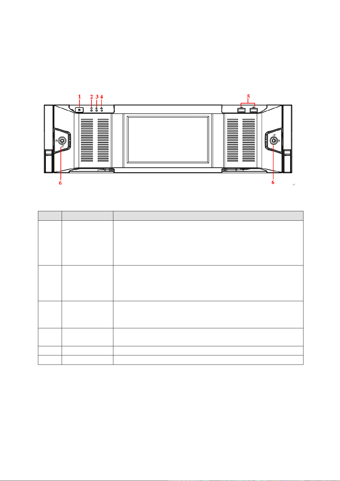
1
Power button
Press it once to turn on the device.
Press it for a long time to turn off the device. (Usually we do not
recommend).
Press power button for a long time or pull out the power cable may
result in device auto restart.
2
System HDD
Indicator light
The blue light flashes when system is reading or writing the system
HDD.
In the system HDD, there are device important configuration file,
factory default configuration file, and device initial boot up data.
3
Alarm indicator
light
The alarm indicator light becomes on once an alarm occurred. It
becomes on via the software detection. The alarm includes local
alarm, no disk and etc.
4
Network
indicator light
The network indicator light is blue and it flashes when you connect the
device to the network.
5
USB port
/ 6 Front panel lock
/
2 Front Panel and Rear Panel
2.1 Front Panel
2.1.1 NVR 6000/6064 Series
For the product of LCD, the front panel is shown as below. See Figure 2-1.
Figure 2-1
Please refer to the following sheet for front panel button information.
Another front panel, it is shown as in Figure 2-2.
9
Page 20
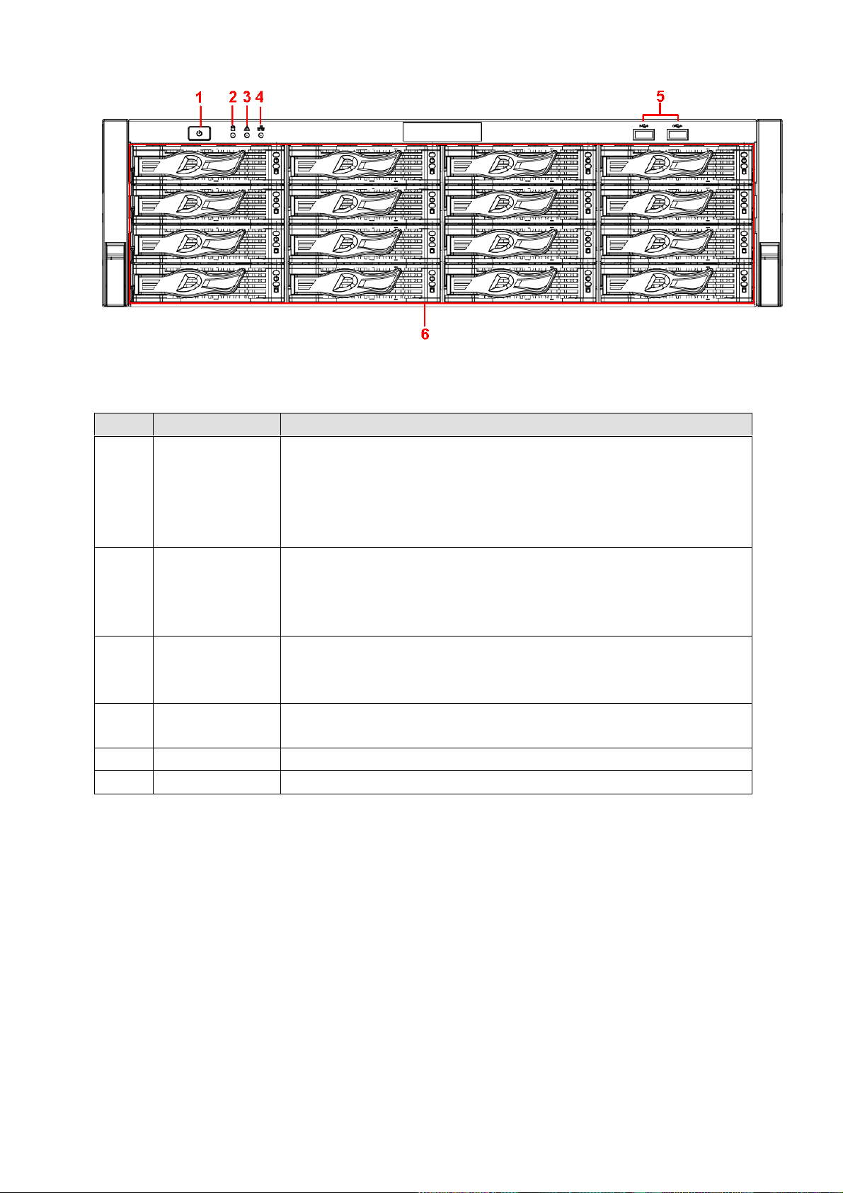
SN
Name
Function
1
Power button
Press it once to turn on the device.
Press it for a long time to turn off the device (Usually we do not
recommend).
Press power button for a long time or pull out the power cable may
result in device auto restart.
2
System HDD
Indicator light
The blue light flashes when system is reading or writing the system
HDD.
In the system HDD, there are device important configuration file,
factory default configuration file, device initial boot up data.
3
Alarm indicator
light
The alarm indicator light becomes on once an alarm occurred. It
becomes on via the software detection. The alarm includes local
alarm, no disk and etc.
4
Network
indicator light
The network indicator light is blue and it flashes when you connect the
device to the network.
5
USB port
/ 6 16 HDD slot
/
Figure 2-2
Please refer to the following sheet for detailed information.
After you remove the front panel, you can see there are 16 HDDs. From the left to the right and from the
top to the bottom, it ranges from 1~4, 5~8, 6~12, 13~16. See Figure 2-3.
You can see there are two indicator lights on the HDD bracket.
The power indicator light is at the top. The light is yellow after you connected the device to the power.
The read-write indicator light is at the bottom. The blue light flashes when system is reading or
writing the data.
10
Page 21
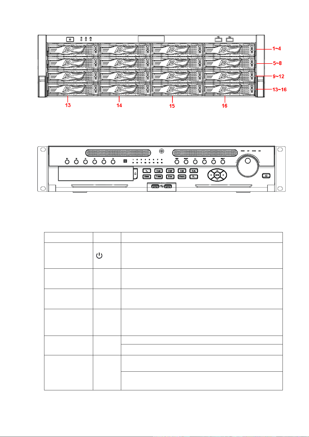
Name
Icon
Function
Power button
Power button, press this button for three seconds to boot up or
shut down NVR.
Number button
0-9 and
etc
Input Arabic number
Switch channel
Record
REC
Manually stop/start recording, working with direction keys
or numeral keys to select the recording channel.
Input number
more than 10
-/--
If you want to input a number more than 10, please click this
button and then input.
ESC
ESC
Go to previous menu, or cancel current operation.
When playback, click it to restore real-time monitor mode.
Assistant
Fn
One-window monitor mode, click this button to display assistant
function: PTZ control and image color.
Backspace function: in numeral control or text control, press it for
1.5seconds to delete the previous character before the cursor.
2.1.2 NVR 600 Series
The front panel is shown as in Figure 2-4.
Figure 2-3
Figure 2-4
Please refer to the following sheet for detailed information.
11
Page 22

In motion detection setup, working with Fn and direction keys to
realize setup.
In text mode, click it to switch between numeral, English
character(small/capitalized) and etc.
In HDD management interface, you can click it to switch HDD
record information and other information (Menu prompt)
Realize other special functions.
Window switch
Mult
Click it to switch one-window/multiple-window.
Shift
In textbox, click this button to switch between numeral,
English(Small/Capitalized),donation and etc.
Enable or disable tour.
Up/
Down
Activate current control, modify setup, and then move up and
down.
Increase/decrease numeral.
Assistant function such as PTZ menu.
Left/
Right
Shift current activated control, and then move left and right.
When playback, click these buttons to control playback bar.
Slow play
Multiple slow play speeds or normal playback.
Fast play
Various fast speeds and normal playback.
Play previous
In playback mode, playback the previous video.
Reverse/Pause
In normal playback or pause mode, click this button to reverse
playback
In reverse playback, click this button to pause playback.
Play Next
In playback mode, playback the next video
Play/Pause
In normal playback click this button to pause playback.
In pause mode, click this button to resume playback.
In backward playback or pause mode, click this button to resume
normal playback.
In real-time monitor mode, click this button to go to the search
menu.
Enter
ENTER
Confirm current operation
Go to default button
Go to menu
12
Page 23
Shuttle(outer
ring)
In real-time monitor mode it works as left/right direction key.
Playback mode, counter clockwise to forward and clock wise to
backward.
Jog(inner dial)
Up/down direction key.
Playback mode, turn the inner dial to realized frame by frame
playback. (Only applies to some special versions.)
USB port
To connect USB storage device, USB mouse and etc.
Channel indicator
light
1-16
It becomes on when system is recording.
IR Receiver
IR
It is to receive the signal from the remote control.
Power indicator
light
POWER
Power indicator light.
Remote control
indicator light
ACT
Remote control indicator light.
Status indicator
light
STATUS
If there is Fn indicator light, current status indicator light is null.
HDD abnormal
indicator light
HDD
The indicator light is on when there is no HDD, HDD error
occurred or HDD capacity is below specified threshold value.
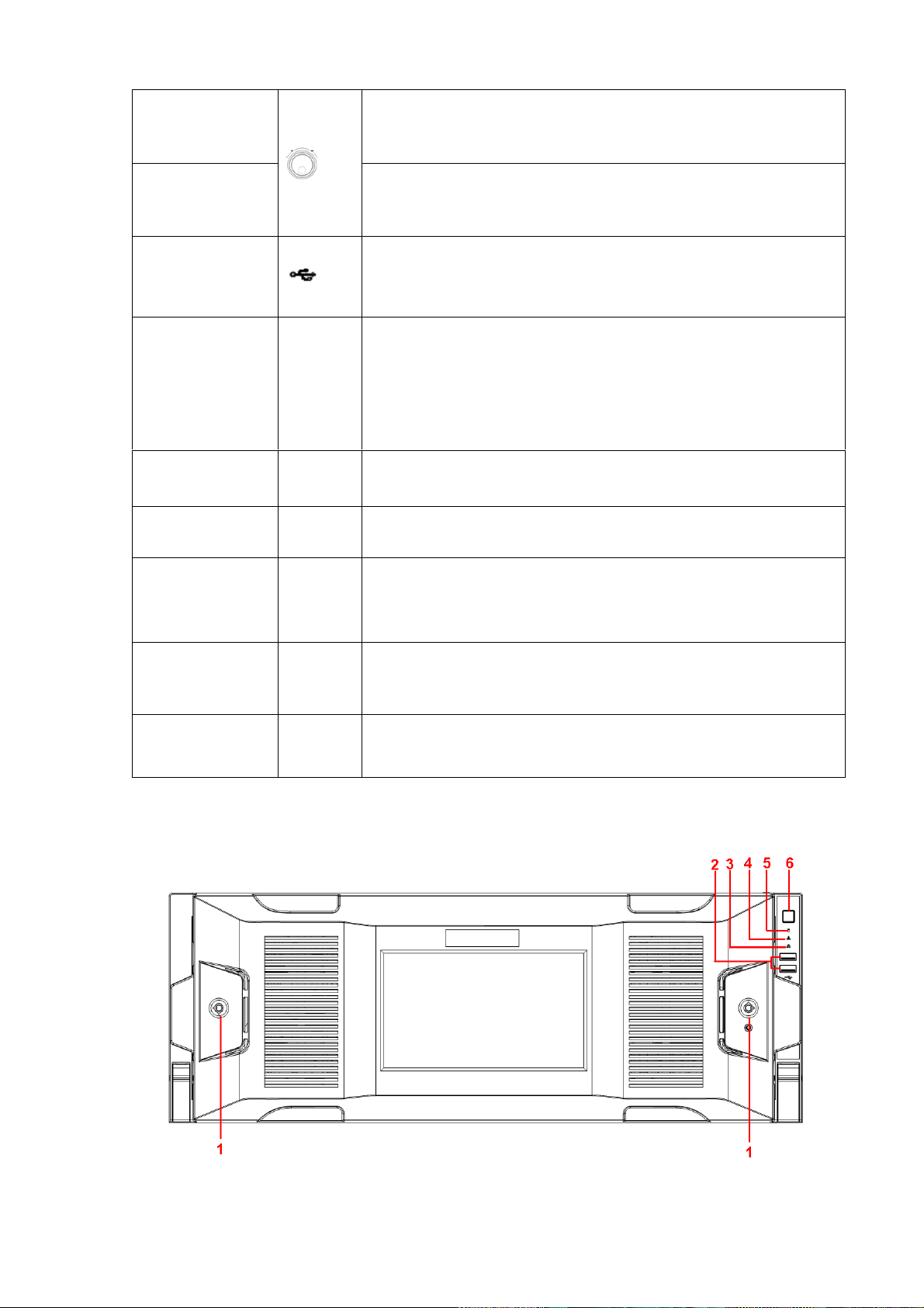
2.1.3 NVR 724 Series
The front panel is shown as in Figure 2-5.
Figure 2-5
13
Page 24
SN
Icon
Name
Function
1
Front panel
lock
/
2 USB port
/
3
Network
indicator light
The network indicator light is blue and it flashes when
you connect the device to the network.
4
Alarm indicator
light
The alarm indicator light becomes on once an alarm
occurred. It becomes on via the software detection. The
alarm includes local alarm, no disk and etc.
5
System HDD
Indicator light
The blue light flashes when system is reading or writing
the system HDD.
In the system HDD, there are device important
configuration file, factory default configuration file,
device initial boot up data.
6 Power button
Press it once to turn on the device.
Press it for a long time to turn off the device (Usually
we do not recommend).
Press power button for a long time or pull out the power
cable may result in device auto restart.
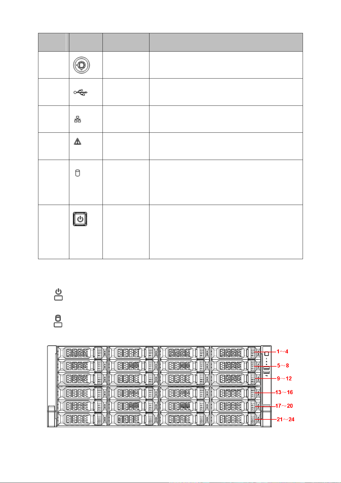
After you remove the front panel, you can see there are 24 HDDs. From the left to the right and from the
top to the bottom, it ranges from 1~4, 5~8, 9~12, 13~16, 17~20, 21~24. See Figure 2-6.
You can see there are two indicator lights on the HDD bracket.
: The power indicator light is at the top. The light is yellow after you connected the device to the
power.
: The read-write indicator light is at the bottom. The blue light flashes when system is reading or
writing the data.
Figure 2-6
14
Page 25
SN
Function
SN
Function
1
Power socket
6
Video VGA output
2
Audio Input
7
eSATA port
3
Audio output
8
USB port
4
Bidirectional talk input
9
HDMI port
5
Network port
10
Alarm input, alarm output, RS485 port.
2.2 Rear Panel
2.2.1 NVR 6000/6064 Series
The general series rear panel is shown as in Figure 2-7.
Figure 2-7
The redundant power series rear panel is shown as in Figure 2-8.
Figure 2-8
Please refer to the following sheet for rear detailed information.
Important
Right now, system does not support audio input port. System supports HDMI1/HDMI2 port by
default. You need to purchase HDMI interface board if you want to use HDMI3-HDMI6 port.
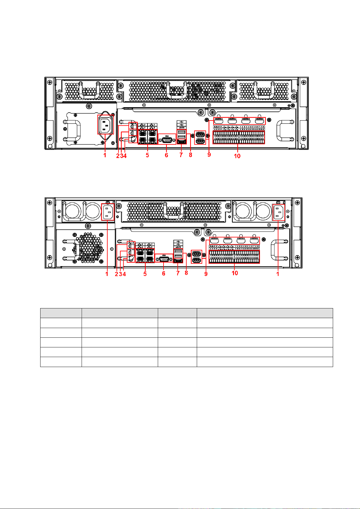
2.2.2 NVR 600 Series
The NVR608 general series rear panel is shown as in Figure 2-9.
15
Page 26
SN
Function
SN
Function
1
Power socket
7
Ethernet port
2
Alarm input, alarm
output, RS485 port.
8
HDMI port
3
RS232 port
9
USB 2.0 port
4
Audio output
10
USB 3.0 port
5
Audio input
11
eSATA port
6
VGA port
Figure 2-9
The NVR608 redundant power series rear panel is shown as in Figure 2-10.
Please refer to the following sheet for detailed information.
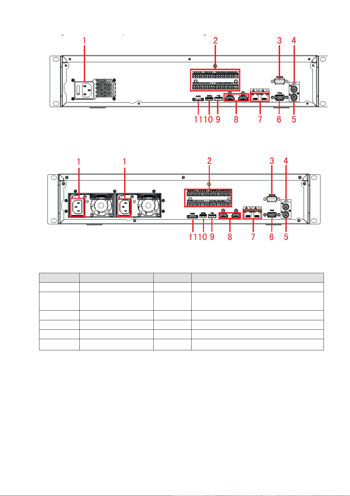
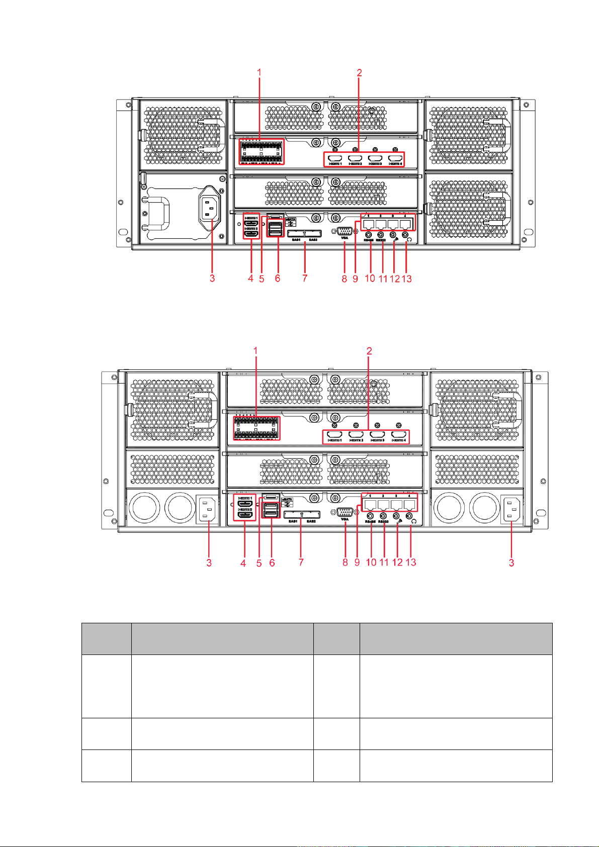
2.2.3 NVR 724 Series
The general rear panel is shown as in Figure 2-11.
Figure 2-10
16
Page 27
SN
Name
SN
Name
1
Alarm input/alarm output
2
HDMI port(Reserved port. Right now
system does not support HD decode
card.)
3
Power port
4
HDMI port
5
eSATA port
6
USB port
Figure 2-11
The redundant power series rear panel is shown as in Figure 2-12.
Please refer to the following sheet for detailed information.
Figure 2-12
17
Page 28
SN
Name
SN
Name
7
SAS port
8
Video VGA output
9
Network port
10
RS485 port
11
RS232(RS422) port
12
Audio input port
13
Audio output port
Icon
Note
2.3 Alarm Connection
Please refer to the following sheet for alarm input and output connection.
There are two alarm input types for you to select: normal open (NO) and normal close (NC).
1. Alarm input
a. Please make sure alarm input mode is grounding alarm input.
b. Grounding signal is needed for alarm input.
c. Alarm input needs the low level voltage signal.
d. Alarm input mode can be either NC (normal Open) or NO (Normal Close)
e. When you are connecting two NVRs or you are connecting one NVR and one other device, please use
a relay to separate them.
2. Alarm output
The alarm output port should not be connected to high power load directly (It shall be less than 1A) to
avoid high current which may result in relay damage. Please use the co contactor to realize the
connection between the alarm output port and the load.
3. Please make sure the front-end device has soundly earthed.
Improper grounding may result in chip damage.
2.3.1 Alarm input and output details
2.3.1.1 NVR 6000/6064 Series
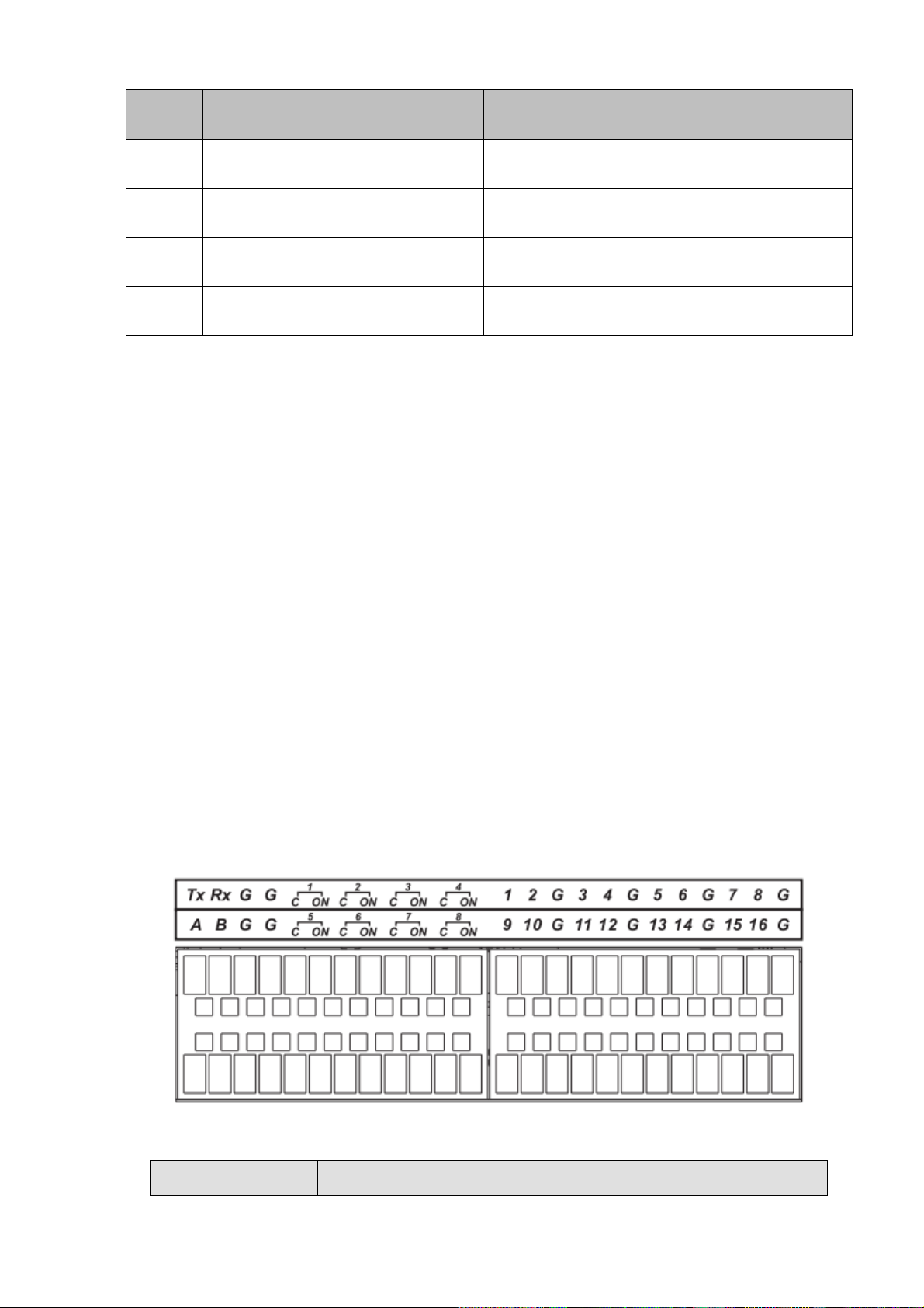
You can refer to the following sheet X for alarm input and output information. See Figure 2-13.
Figure 2-13
18
Page 29
1,2,3,4,5,6,
7,8,9,10 ,11,
12,13,14,15,16
ALARM 1 to ALARM 16. The alarm becomes active in low voltage.
1-ON C,2-ON C,
3-ON C,4-ON C,
5-ON C,6-ON C,
7-ON C,8-ON C
Eight groups of normal open activation output (on/off button)
G
GND cable.
A/B
The A/B cable to control the RS485 devices. It is to connect to
control decoder such as the recorder.
Tx and Rx
RS232 port. Tx is the data output cable and the Rx is the data input
cable.
Icon
Note
1,2,3,4,5,6,
7,8,9,10 ,11,
12,13,14,15,16
ALARM 1 to ALARM 16. The alarm becomes active in low voltage.
1-ON C,2-ON C,
3-ON C,4-ON C,
5-ON C,6-ON C,
7-ON C,8-ON C
Eight groups of normal open activation output (on/off button)
GND cable.
A/B
The A/B cable to control the RS485 devices. It is to connect to
control decoder such as the recorder.
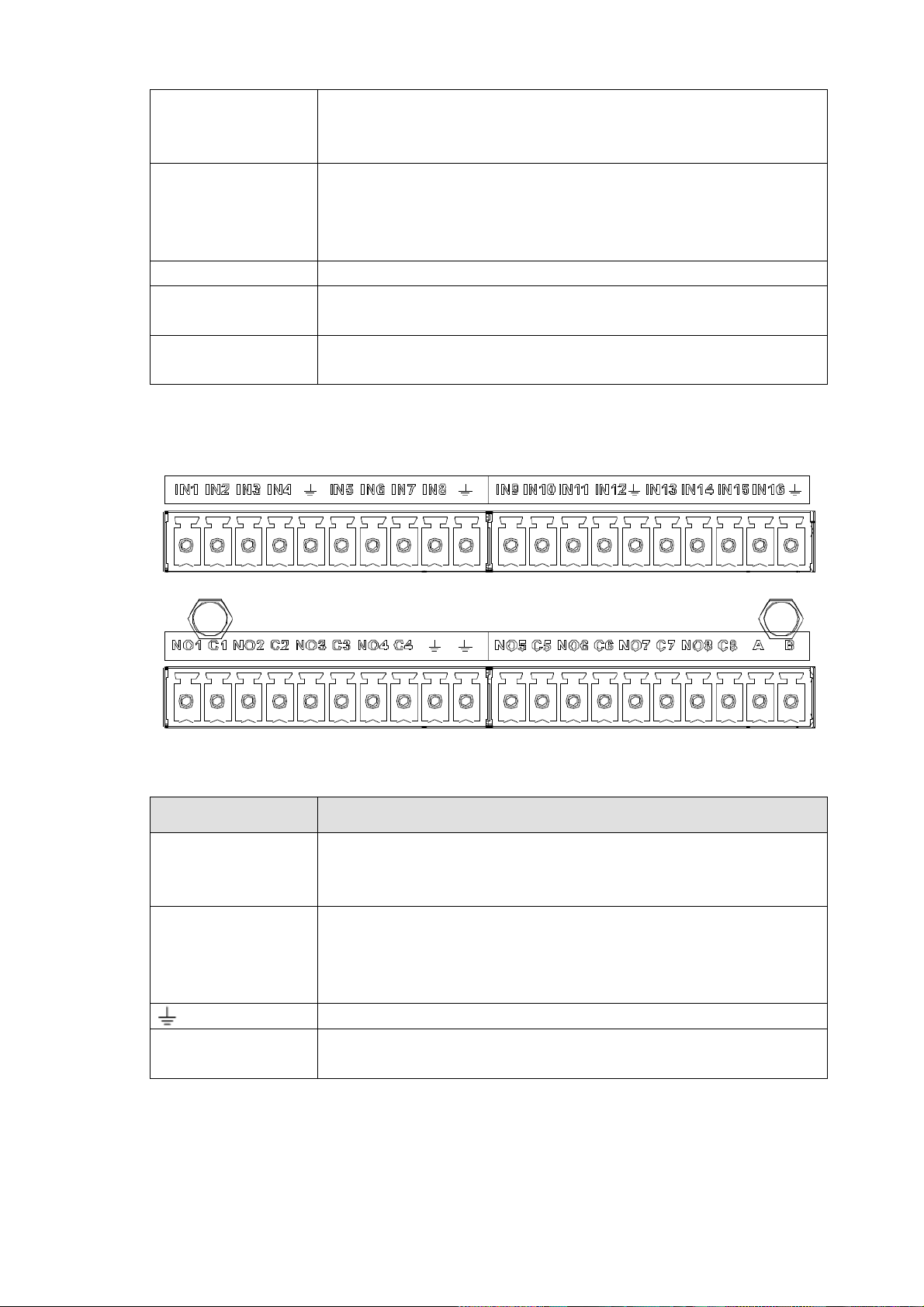
2.3.1.2 NVR 608 Series
You can refer to the following sheet X for alarm input and output information. See Figure 2-14.
Figure 2-14
2.3.1.3 NVR 724 Series
You can refer to the following sheet X for alarm input and output information. See Figure 2-15.
19
Page 30
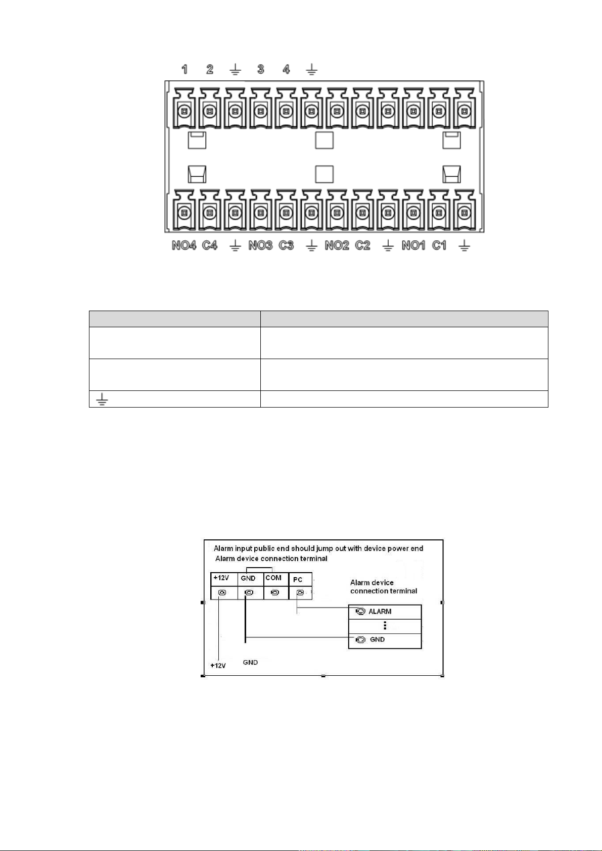
Icon
Note
1~4
ALARM 1 to ALARM 4. The alarm becomes active in low
voltage.
NO1 C1,NO2 C2,NO3 C3,NO4
C4
Four groups of normal open activation output (on/off
button)
GND
Figure 2-15
2.3.2 Alarm input and output port
Please refer to the following sheet for more information.
Grounding alarm inputs. Normal open or Normal close type)
Please parallel connect COM end and GND end of the alarm detector (Provide external power to the
alarm detector).
Please parallel connect the Ground of the NVR and the ground of the alarm detector.
Please connect the NC port of the alarm sensor to the NVR alarm input(ALARM)
Use the same ground with that of NVR if you use external power to the alarm device.
Figure 2-16
2.3.3 Alarm Output Port
Provide power to peripheral alarm device.
To avoid overloading, please read the following relay parameters sheet carefully.
RS485 A/B cable is for the A/B cable of the PTZ decoder.
20
Page 31

Model:
JRC-27F
Material of the
touch
Silver
Rating
(Resistance
Load)
Rated switch capacity
30VDC 2A, 125VAC 1A
Maximum switch power
125VA 160W
Maximum switch voltage
250VAC, 220VDC
Maximum switch currency
1A
Insulation
Between touches with same
polarity
1000VAC 1minute
Between touches with different
polarity
1000VAC 1minute
Between touch and winding
1000VAC 1minute
Surge voltage
Between touches with same
polarity
1500V (10×160us)
Length of open
time
3ms max
Length of close
time
3ms max
Longevity
Mechanical
50×106 MIN (3Hz)
Electrical
200×103 MIN (0.5Hz)
Temperature
-40℃ ~+70℃
Left click
mouse
When you have selected one menu item, left click mouse to view menu content.
Modify checkbox or motion detection status.
Click combo box to pop up dropdown list
2.3.4 Alarm relay specifications
2.4 Mouse Operation
Please refer to the following sheet for mouse operation instruction.
21
Page 32

In input box, you can select input methods. Left click the corresponding button
on the panel you can input numeral/English character (small/capitalized). Here
← stands for backspace button. _ stands for space button.
In English input mode: _stands for input a backspace icon and ← stands for
deleting the previous character.
In numeral input mode: _ stands for clear and ← stands for deleting the
previous numeral.
Double left
click mouse
Implement special control operation such as double click one item in the file list
to playback the video.
In multiple-window mode, double left click one channel to view in full-window.
Double left click current video again to go back to previous multiple-window
mode.
Right click
mouse
In real-time monitor mode, pops up shortcut menu.
Exit current menu without saving the modification.
Press middle
button
In numeral input box: Increase or decrease numeral value.
Switch the items in the check box.
Page up or page down
Move mouse
Select current control or move control
Drag mouse
Select motion detection zone
Select privacy mask zone.
22
Page 33

3 Local Basic Operation
3.1 Boot up and Shutdown
3.1.1 Boot up
Before the boot up, please make sure:
The rated input voltage matches the device power on-off button. Please make sure the power wire
connection is OK. Then click the power on-off button.
Always use the stable current, if necessary UPS is a best alternative measure.
Please follow the steps listed below to boot up the device.
Connect the device to the monitor and then connect a mouse.
Connect power cable.
Click the power button at the front or rear panel and then boot up the device. After device booted up,
the system is in multiple-channel display mode by default.
3.1.2 Shutdown
Note
When you see corresponding dialogue box “System is shutting down…” Do not click power on-off
button directly.
Do not unplug the power cable or click power on-off button to shutdown device directly when device
is running (especially when it is recording.)
There are three ways for you to log out.
a) Main menu (RECOMMENDED)
From Main Menu->Shutdown, select shutdown from dropdown list.
Click OK button, you can see device shuts down.
b) From power on-off button on the front panel or remote control
Press the power on-off button on the NVR front panel or remote control for more than 3 seconds to
shutdown the device.
c) From power on-off button on the rear panel.
3.2 Startup Wizard
After device successfully booted up, it goes to startup wizard.
Click Cancel/Next button, you can see system goes to login interface.
Tips
Check the box Startup button here, system goes to startup wizard again when it boots up the next time.
Cancel the Startup button, system goes to the login interface directly when it boots up the next time.
23
Page 34

Figure 3-1
Click Cancel button or Next Step button, system goes to login interface. See Figure 3-2.
System consists of four accounts:
Username: admin. Password: admin. (administrator, local and network)
Username: 888888. Password: 888888. (administrator, local only)
Username: 666666. Password: 666666(Lower authority user who can only monitor, playback,
backup and etc.)
Username: default. Password: default (hidden user). Hidden user “default” is for system interior use
only and can not be deleted. When there is no login user, hidden user “default” automatically login.
You can set some rights such as monitor for this user so that you can view some channel view
without login.
Figure 3-2
Note:
For security reason, please modify password after you first login.
Within 30 minutes, three times login failure will result in system alarm and five times login failure will result
in account lock!
Click OK button, you can go to General interface. See Figure 3-3.
For detailed information, please refer to chapter 3.13.1.
24
Page 35

Figure 3-3
Click Next button, you can go to network interface. See Figure 3-4.
For detailed information, please refer to chapter 3.11.
Figure 3-4
Click Next button, you can go to remote device interface. See Figure 3-5.
For detailed information, please refer to chapter 3.4.
25
Page 36

Figure 3-5
Click Next button, you can go to RAID interface. See Figure 3-6.
For detailed information, please refer to chapter 3.12.4.
Figure 3-6
Click Next button, you can go to Schedule interface. See Figure 3-7.
26
Page 37

For detailed information, please refer to chapter 3.7.2.
Figure 3-7
Click Finish button, system pops up a dialogue box. Click the OK button, the startup wizard is complete.
See Figure 3-8.
Figure 3-8
3.3 Navigation Bar
You need to go to the Main menu->Setting->System->General to enable navigation bar function;
otherwise you can not see the following interface.
The navigation bar is shown as below. See Figure 3-9.
Figure 3-9
27
Page 38

3.3.1 Main Menu
Click button to go to the main menu interface.
3.3.2 Dual-screen operation
Important
This function is for some series only.
Click to select screen 2, you can view an interface shown as below. See Figure 3-10. It is a
navigation bar for screen 2.
Figure 3-10
Click any screen split mode; HDMI2 screen can display corresponding screens. Now you can control two
screens. See Figure 3-11.
Figure 3-11
Note
Screen 2 function is null if tour is in process. Please disable tour function first,
Right now, the screen 2 operation can only be realized on the navigation bard. The operations on the
right-click menu are for screen 1 only.
3.3.3 Output Screen
Select corresponding window-split mode and output channels.
3.3.4 Tour
Click button to enable tour, the icon becomes , you can see the tour is in process.
3.3.5 PTZ
Click , system goes to the PTZ control interface. Please refer to chapter 3.6.2.
3.3.6 Color
Click button , system goes to the color interface. Please refer to chapter 3.4.3.
Please make sure system is in one-channel mode.
3.3.7 Search
Click button , system goes to search interface. Please refer to chapter 3.8.2
3.3.8 Alarm Status
28
Page 39

Click button , system goes to alarm status interface. It is to view device status and channel status.
Please refer to chapter 3.14.1.4.
3.3.9 Channel Info
Click button , system goes to the channel information setup interface. It is to view information of the
corresponding channel. See Figure 3-12.
Figure 3-12
3.3.10 Remote Device
Click , system goes to the remote device interface. Please refer to chapter 3.4.
3.3.11 Network
Click , system goes to the network interface. It is to set network IP address, default gateway and etc.
Please refer to chapter 3.11.
3.3.12 HDD Manager
Click , system goes to the HDD manager interface. It is to view and manage HDD information.
Please refer to chapter 3.12.1.
3.3.13 USB Manager
29
Page 40

Click , system goes to the USB Manager interface. See Figure 3-13. It is to view USB information,
backup and update. Please refer to chapter 3.9.1 file backup, chapter 3.9.3 backup log, chapter3.9.2
import/export, and chapter 3.14.4 upgrade for detailed information.
Figure 3-13
3.3.14 System Status
Click , you can go to the following interface. See Figure 3-14. Here you can view host information,
RAID information, HDD information, HDD usage rate, fan speed, CPU usage, CPU temperature, memory
usage, power informaiton and etc.
The following interface is based on our single-power series product.
Figure 3-14
30
Page 41

3.4 Remote Device
3.4.1 Remote Device Connection
From Mani menu->Setting->Remote->Remote or right click mouse on the preview interface and then
select remote device item, you can see the following interface. See Figure 3-15.
Figure 3-15
Click Device search button, you can view the searched IP addresses at the top pane of the interface.
Double click an IP address or check one IP address and then click Add button, you can add current
device to the bottom pane of the interface. System supports batch add function.
Click Manual Add button, you can add a device directly. Here you can set TCP/UPD/auto connection
mode. The default setup is TCP. See Figure 3-16.
Important
Please note the manual add function is for Dahua, Panasonic, Sony, Dynacolor, Samsung, AXIS, Arecont,
ONVIF and Custom. When the type is the custom, you can just input URL address, user name and
password connect to the network camera without considering network camera manufacture. Please
contact your network camera manufacturer for the URL address.
31
Page 42

Figure 3-16
3.4.2 Short-Cut Menu
In the preview interface, for the channel of no IPC connection, you can click the icon “+” in the centre of
the interface to quickly go to the Remote Device interface. See Figure 3-17.
Figure 3-17
3.4.3 Image
From main menu->Setting->Camera->Image, you can see the image interface is shown as below.
See Figure 3-18.
Channel: Select a channel from the dropdown list.
Config file: The options includes: day/night/general/switch by period. Once the mode is switch by
period, you can set sunset and sunrise time.
32
Page 43

Saturation: It is to adjust monitor window saturation. The value ranges from 0 to 100. The default
value is 50. The larger the number, the strong the color is. This value has no effect on the general
brightness of the whole video. The video color may become too strong if the value is too high. For
the grey part of the video, the distortion may occur if the white balance is not accurate. Please note
the video may not be attractive if the value is too low. The recommended value ranges from 40 to 60.
Brightness: It is to adjust monitor window bright. The value ranges from 0 to 100. The default value is
50. The larger the number is, the bright the video is. When you input the value here, the bright
section and the dark section of the video will be adjusted accordingly. You can use this function
when the whole video is too dark or too bright. Please note the video may become hazy if the value
is too high. The recommended value ranges from 40 to 60.
Contrast: It is to adjust monitor window contrast. The value ranges from 0 to 100. The default value
is 50. The larger the number is, the higher the contrast is. You can use this function when the whole
video bright is OK but the contrast is not proper. Please note the video may become hazy if the value
is too low. If this value is too high, the dark section may lack brightness while the bright section may
over exposure .The recommended value ranges from 40 to 60.
Auto Iris: It is for the device of the auto lens. You can check the box before ON to enable this
function. The auto iris may change if the light becomes different. When you disable this function, the
iris is at the max. System does not add the auto iris function in the exposure control. This function is
on by default.
Mirror: It is to switch video up and bottom limit. This function is disabled by default.
Flip: It is to switch video left and right limit. This function is disabled by default.
3D NR: It is to process multiple-frame (At least two frames). System uses the information between
these two frames to realize noise reduction function.
BLC: It includes several options: BLC/WDR/HLC/OFF.
BLC: There are two modes: default/customize. For the default mode, the device auto exposures
according to the environments situation so that the darkest area of the video is clearer. For the
custmize mode, you can select a rectangle zone to enhance its brightness to the proper level.
WDR: For the WDR scene, this function can lower the high bright section and enhance the
brightness of the low bright section. So that you can view these two sections clearly at the same time.
The value ranges from 1 to 100. When you switch the camera from no-WDR mode to the WDR mode,
system may lose several seconds record video.
HLC: After you enabled HLC function, the device can lower the brightness of the brightest section
according to the HLC control level. It can reduce the area of the halo and lower the brightness of the
whole video.
OFF: It is to disable the BLC function. Please note this function is disabled by default.
Profile: It is to set the white balance mode. It has effect on the general hue of the video. This function
is on by default. You can select the different scene mode such as auto, sunny, cloudy, home, office,
night, disable and etc to adjust the video to the best quality.
Auto: The auto white balance is on. System can auto compensate the color temperature to make
sure the vide color is proper.
Sunny: The threshold of the white balance is in the sunny mode.
Night: The threshold of the white balance is in the night mode.
Customized: You can set the gain of the red/blue channel. The value reneges from 0 to 100.
Day/night. It is to set device color and the B/W mode switch. The default setup is auto.
Color: Device outputs the color video.
33
Page 44

Auto: Device auto select to output the color or the B/W video according to the device feature (The
general bright of the video or there is IR light or not.)
B/W: The device outputs the black and white video.
Sensor: It is to set when there is peripheral connected IR light. Please note some non-IR series
product support sensor input function.
Figure 3-18
3.4.4 Channel Name
From main menu->Setting->Camera->Channel name, you can see an interface shown as in Figure 3-19.
It is to modify channel name. It max supports 31-character.
Please note you can only modify the channel name of the connected network camera.
34
Page 45

Figure 3-19
3.4.5 Upgrade
Important
System max supports to upgrade 8 network cameras at the same time.
It is to update the network camera.
From main menu->Setting->Camera->Remote->Upgrade, the interface is shown as below. See Figure
3-20.
Click Browse button and then select the upgrade file. Then select a channel (or you can select device
type filter to select several devices at the same time.)
Click Begin button to upgrade. You can see the corresponding dialogue once the upgrade is finish.
35
Page 46

Figure 3-20
3.5 Preview
After device booted up, the system is in multiple-channel display mode. See Figure 3-21.Please note the
displayed window amount may vary. The following figure is for reference only. Please refer to chapter 1.3
Specifications for the window-amount your product supported.
Figure 3-21
3.5.1 Preview
If you want to change system date and time, you can refer to general settings (Main
36
Page 47

1
Current channel pops up
this icon when it is
recording.
3
Current channel pops up this icon
when video loss alarm occurs.
2
Current channel pops up
this icon when motion
detect alarm occurs.
4
Current channel pops up this icon
when it is in monitor lock status.
5
System exceeds
decoded channel
amount.
1 2 3 4 5 6
Menu->Setting->System->General). If you want to modify the channel name, please refer to the
display settings (Main Menu->Camera->CAM name)
Please refer to the following sheet for detailed information.
Tips
Preview drag: If you want to change position of channel 1 and channel 2 when you are
previewing, you can left click mouse in the channel 1 and then drag to channel 2, release mouse
you can switch channel 1 and channel 2 positions.
Use mouse middle button to control window split: You can use mouse middle button to switch
window split amount.
3.5.2 Preview control interface
Move you mouse to the top centre of the video of current channel, you can see system pops up the
preview control interface. See Figure 3-22. If your mouse stays in this area for more than 6 seconds
and has no operation, the control bar automatically hides.
Figure 3-22
1) Realtime playback
It is to playback the previous 5-60 minutes record of current channel.
Please go to the Main menu->Setting->->System->General to set real-time playback time.
System may pop up a dialogue box if there is no such record in current channel.
2) Digital zoom
It is to zoom in specified zone of current channel. It supports zoom in function of multiple-channel.
Click button , the button is shown as .
There are two ways for you to zoom in.
Drag the mouse to select a zone, you can view an interface show as Figure 3-23.
37
Page 48

Figure 3-23
Put the middle button at the centre of the zone you want to zoom in, and move the mouse, you
can view an interface shown as in Figure 3-24.
Figure 3-24
Right click mouse to cancel zoom and go back to the original interface.
3) Manual record function
It is to backup the video of current channel to the USB device. System can not backup the video of
multiple-channel at the same time.
Click button , system begins recording. Click it again, system stops recoridng. You can find the record
file on the flash disk.
4) Manual Snapshot
Click to snapshot 1-5 times. The snapshot file is saved on the USB device or HDD. You can go to
the Search interface (chapter 3.8) to view.
5) Bidirectional talk
If the connected front-end device supports bidirectional talk function, you can click this button. Click
button to start bidirectional talk function the icon now is shown as . Now the rest
bidirectional talk buttons of digital channel becomes null too.
Click again, you can cancel bidirectional talk and the bidirectional talk buttons of other digital
channels become as .
6) Remote device
Shortcut menu. Click it to go to the remote device interface to add/delete remote device or view its
corresponding information. Please refer to chapter3.4.2 for detailed information.
3.5.3 Right Click Menu
38
Page 49

After you logged in the device, right click mouse, you can see the short cut menu. Please see Figure
3-25.
Window split mode: You can select window amount and then select channels.
PTZ: Click it to go to PTZ interface.
Auto focus: It is to set auto focus function. Please make sure the connected network camera
supports this function.
Image: Set video corresponding information.
Search: Click it to go to Search interface to search and playback a record file.
Record control: Enable/disable record channel.
Alarm output: It is to set alarm output mode.
Remote: Search and add a remote device.
Alarm output: Generate alarm output signal manually.
Main menu: Go to system main menu interface.
Tips:
Right click mouse to go back to the previous interface.
Figure 3-25
3.5.4 Preview Display Effect Setup
3.5.4.1 Display From Main Menu->Setting->System->Display, you can go to the following interface. See Figure 3-26. Here you can set menu and video preview effect. All you operation here does not affect the record file and playback effect.
39
Page 50

Figure 3-26
Now you can set corresponding information.
Time display: You can select to display time or not when system is playback.
Channel display: You can select to channel name or not when system is playback.
Image enhance: Check the box; you can optimize the margin of the preview video.
Screen mode: It is for dual-screen operation. Please select from the dropdown list according to your
actual situation. Click Apply button, system needs to restart to activate new setup. For example,
32+4 means for VGA, system max supports 32-window split and for HDMI2, system max supports
4-window split.
Screen enable: Check the box here to enable the screen. In this way, it can display the video.
Screen No. Select the corresponding screen from the dropdown list and then set resolution.
Resolution: There are four options: 1920×1080, 1280×1024, 1280×720, 1024×768. The VGA default
resolution is 1280×1024; HDMI default resolution is 1920×1080. Please note the system needs to
reboot to activate current setup.
Click OK button to save current setup.
3.5.4.2 Preview Tour Parameters Set preview display mode, channel display sequence and tour setup. Set preview display mode: On the preview interface, right click mouse, you can view right-click menu.
Now you can select preview window amount and channel.
Set channel display mode: On the preview interface, if you want to change channel 1 and channel 16
position, please right click channel 1 video window and then drag to the channel 16 video window,
release button, you can change channel 1 and channel 16 position.
Tour setup: Here you can set preview window channel display mode and interval. Please follow the
40
Page 51

steps listed below.
From Main menu->Setting->System->Display->Tour, you can see an interface shown as in Figure 3-27.
Here you can set tour parameter.
Screen No.: Please select screen from the dropdown list.
Video detect: It is to set video detect tour. System supports 1/8-window tour.
Alarm: It is to set alarm tour. System supports 1/8-window tour.
Enable tour: Check the box here to enable tour function.
Interval: Input proper interval value here. The value ranges from 1-120 seconds.
Window split: It is to set window split mode.
Figure 3-27
Tips
On the navigation bar, click / to enable/disable tour.
Click Save button to save current setup.
3.6 PTZ
Note:
Before you control the PTZ, please make sure the PTZ decoder and the NVR network
connection is OK and the corresponding settings are right.
3.6.1 PTZ Settings
Cable Connection
Please follow the procedures below to go on cable connection
Connect the dome RS485 port to NVR RS485 port.
Connect dome video output cable to NVR video input port.
Connect power adapter to the dome.
41
Page 52

In the main menu, from Setting->System->PTZ, you can see an interface is shown as in Figure 3-28.
Here you can set the following items:
Channel: Select the current camera channel.
PTZ type: There are two types: local/remote. Please select local mode if you are connect RS485
cable to connect to the Speed dome (PTZ). Please select remote mode if you are connecting to the
network PTZ camera.
Protocol: Select corresponding PTZ protocol(such as PELCOD)
Address: Default address is 1.
Baud rate: Select corresponding baud rate. Default value is 9600.
Data bit: Select corresponding data bits. Default value is 8.
Stop bit: Select corresponding stop bits. Default value is 1.
Parity: There are three options: odd/even/none. Default setup is none.
Figure 3-28
If you are connecting to network PTZ, the PTZ type shall be remote. See Figure 3-29.
42
Page 53

Figure 3-29
3.6.2 PTZ Control
After completing all the setting please click save button. Right click mouse (click “Fn” Button in the
front panel or click “Fn” key in the remote control). The interface is shown as in Figure 3-30. Please
note you can only go to the PTZ control interface when you are in 1-window display mode.
Figure 3-30
The PTZ setup is shown as in See Figure 3-31.
Please note the commend name is grey once device does not support this function.
The PTZ operation is only valid in one-window mode.
Here you can control PTZ direction, speed, zoom, focus, iris, preset, tour, scan, pattern aux function, light
43
Page 54

Name
Function
key
function
Shortcut
key
Function
key
function
Shortcut
key
Zoom
Near
Far
Focus
Near
│
Far
►│
Iris close
Open
and wiper, rotation and etc.
Speed is to control PTZ movement speed. The value ranges from 1 to 8.The speed 8 is faster than speed
1. You can use the remote control to click the small keyboard to set.
You can click and of the zoom, focus and iris to zoom in/out, definition and brightness.
The PTZ rotation supports 8 directions. If you are using direction buttons on the front panel, there are only
four directions: up/down/left/right.
Figure 3-31
In the middle of the eight direction arrows, there is a 3D intelligent positioning key. See Figure 3-32.
Please make sure your protocol supports this function and you need to use mouse to control.
Click this key, system goes back to the single screen mode. Drag the mouse in the screen to adjust
section size. The dragged zone supports 4X to 16X speeds. It can realize PTZ automatically. The smaller
zone you dragged, the higher the speed.
Figure 3-32
In Figure 3-31, click to open the menu, you can set preset, tour, pattern, scan and etc. See
Figure 3-33.
44
Page 55

Icon
Function
Icon
Function
Preset
Flip
Tour
Reset
Pattern
Aux
Scan
Aux on-off
button
Rotate
Go to menu
Figure 3-33
Please refer to the following sheet for detailed information.
Please note the above interface may vary due to different protocols. The button is grey and can not
be selected once the current function is null.
Right click mouse or click the ESC button at the front panel to go back to the Figure 3-31.
3.6.2.1 PTZ Function Setup
Click , you can go to the following interface to set preset, tour, pattern, and scan. See Figure 3-34.
Figure 3-34
Preset Setup
In Figure 3-34, click preset button and use eight direction arrows to adjust camera to the proper position.
The interface is shown as in Figure 3-35.
Click Set button and then input preset number.
Click Set button to save current preset.
45
Page 56

Figure 3-35
Tour Setup
In Figure 3-34, click tour button.
Input tour value and preset No. Click Add preset button to add current preset to the tour. See Figure 3-36.
Tips
Repeat the above steps to add more presets to the tour. Click Del preset button to remove it from the tour.
Please note some protocols do not support delete preset function.
Figure 3-36
Pattern Setup
In Figure 3-34, click Pattern button and input pattern number.
Click Begin button to start direction operation. Or you can go back to Figure 3-31 to operate
zoom/focus/iris/direction operation.
In Figure 3-34, click End button.
46
Page 57

Figure 3-37
Scan Setup
In Figure 3-34, click Scan button.
Use direction buttons to set camera left limit and then click Left button.
Use direction buttons to set camera right limit and then click Right button. Now the scan setup process is
complete.
Figure 3-38
3.6.2.2 Call PTZ Function
Call Preset
In Figure 3-33, input preset value and then click to call a preset. Click again to stop call.
Call Pattern
In Figure 3-33, input pattern value and then click to call a pattern. Click again to stop
call.
Call Tour
In Figure 3-33, input tour value and then click to call a tour. Click again to stop call.
47
Page 58

Call Scan
In Figure 3-33, input Scan value and then click to call a tour. Click again to stop call.
Rotate
In Figure 3-33, click to enable the camera to rotate.
System supports preset, tour, pattern, scan, rotate, light and etc function.
Note:
Preset, tour and pattern all need the value to be the control parameters. You can define it as you
require.
You need to refer to your camera user’s manual for Aux definition. In some cases, it can be used for
special process.
Aux
Click , system goes to the following interface. The options here are defined by the protocol. The aux
number is corresponding to the aux on-off button of the decoder. See Figure 3-39.
Figure 3-39
3.7 Record and Snapshot
The record/snapshot priority is: Alarm->Motion detect->Schedule.
3.7.1 Encode
3.7.1.1 Encode
Encode setting is to set IPC encode mode, resolution, bit stream type and etc.
From Main menu->Setting->System->Encode, you can see the following interface. See Figure 3-40.
Channel: Select the channel you want.
Type: Please select from the dropdown list. There are three options: regular/motion detect/alarm.
You can set the various encode parameters for different record types.
Compression: System supports H.264, MPEG4, MJPEG and etc.
Resolution: The mainstream resolution type is IPC’s encoding config. Generally there is
D1/720P/1080P.
Frame rate: It ranges from 1f/s to 25f/s in NTSC mode and 1f/s to 30f/s in PAL mode.
Bit rate type: System supports two types: CBR and VBR. In VBR mode, you can set video quality.
48
Page 59

Video/audio: You can enable or disable the video/audio. Please note, once you enable audio
function for one channel, system may enable audio function of the rest channels by default.
Copy:After you complete the setup, you can click Copy button to copy current setup to other
channel(s). You can see an interface is shown as in Figure 3-47. You can see current channel
number is grey. Please check the number to select the channel or you can check the box ALL.
Please click the OK button in Figure 3-47 and Figure 3-41 respectively to complete the setup. Please
note, once you check the All box, you set same encode setup for all channels. Audio/video enable
box, overlay button and the copy button is shield.
Please highlight icon to select the corresponding function.
Figure 3-40
3.7.1.2 Overlay
Click overlay button, you can see an interface is shown in Figure 3-41.
Cover area: Here is for you to cover area section. You can drag you mouse to set proper section size.
In one channel video, system max supports 4 zones in one channel. You can set with Fn button or
direction buttons.
Preview/monitor: The cover area has two types. Preview and Monitor. Preview means the privacy
mask zone can not be viewed by user when system is in preview status. Monitor means the privacy
mask zone can not be view by the user when system is in monitor status.
Time display: You can select system displays time or not when you playback. Please click set button
and then drag the title to the corresponding position in the screen.
Channel display: You can select system displays channel number or not when you playback. Please
click set button and then drag the title to the corresponding position in the screen.
Customized title: System supports five customized titles.
49
Page 60

Figure 3-41
3.7.2 Schedule
The record type priority is: Alarm>Motion detect>Regular.
3.7.2.1 Schedule Record
Set record time, record plan and etc. Please note system is in 24-hour record by default after its first
boot up.
In the main menu, from Main menu->Setting->Storage->Schedule, you can go to schedule menu.
See Figure 3-45. There are total six periods.
Channel: Please select the channel number first. You can select “all” if you want to set for the whole
channels.
: Sync connection icon. Select icon of several dates, all checked items can be edited or
together. Now the icon is shown as .
: Click it to delete a record type from one period.
Record Type: Please check the box to select corresponding record type. There are four types:
Regular/MD (motion detect)/Alarm/MD&Alarm.
Week day: There are eight options: ranges from Saturday to Sunday and all.
Holiday: It is to set holiday setup. Please note you need to go to the General interface (Main
Menu->Setting->System->General) to add holiday first. Otherwise you can not see this item.
Pre-record: System can pre-record the video before the event occurs into the file. The value ranges
from 1 to 30 seconds depending on the bit stream.
50
Page 61

Redundancy: System supports redundancy backup function. It allows you backup recorded file in
two disks. You can highlight Redundancy button to activate this function. Please note, before enable
this function, please set at least one HDD as redundant. (Main menu->Setting->Storage->HDD
Manager). Please note this function is null if there is only one HDD.
ANR: It is to save video to the SD card of the network camera in case the network connection fails.
The value ranges from 0s~43200s. After the network connection resumed, the system can get the
video from the SD card and there is no risk of record loss.
Period setup: Click button after one date or a holiday, you can see an interface shown as in
Figure 3-46.There are five record types: regular, motion detection (MD), Alarm, MD & alarm, and
intelligence.
Please following the steps listed below to draw the period manually.
a) Select a channel you want to set. See Figure 3-42.
Figure 3-42
b) Set record type. See Figure 3-43.
Figure 3-43
c) Please draw manually to set record period. There are six periods in one day. See Figure 3-44.
Figure 3-44
Please check the box to select the corresponding function. After completing all the setups please
click save button, system goes back to the previous menu.
There are color bars for your reference. Green color stands for regular recording, yellow color stands
for motion detection and red color stands for alarm recording, and orange color stands for intelligent
alarm. The white means the MD and alarm record is valid. Once you have set to record when the MD
and alarm occurs, system will not record neither motion detect occurs nor the alarm occurs.
51
Page 62

Figure 3-45
Figure 3-46
Quick Setup
Copy function allows you to copy one channel setup to another. After setting in channel 1, click Copy
button, you can go to interface Figure 3-47. You can see current channel name is grey such as channel 1.
Now you can select the channel you wan to paste such as channel 5/6/7. If you wan to save current setup
of channel 1 to all channels, you can click the first box “ALL”. Click the OK button to save current copy
setup. Click the OK button in the Encode interface, the copy function succeeded.
Please note, if you select ALL in Figure 3-47, the record setup of all channels are the same and the Copy
52
Page 63

button becomes hidden.
Figure 3-47
Click OK button to save current setup.
3.7.2.2 Schedule Snapshot
From Main menu->Setting->Storage->Record or on the preview interface, right click mouse and then
select record item, you can see Figure 3-48.
Select snapshot channel and enable snapshot function. Click Save button.
Figure 3-48
From Main menu->Setting->Camera->Encode->Snapshot, you can go to snapshot interface. See Figure
3-49.
Select the snapshot channel from the dropdown list and then select snapshot mode as Timing (Schedule)
from the dropdown list and then set picture size, quality and snapshot frequency.
53
Page 64

Figure 3-49
In the main menu, from Main menu->Setting->Storage->Schedule, you can go to schedule menu.
See Figure 3-45. Here you can set snapshot period. There are total six periods in one day. Please refer
to chapter 3.7.2.1 for detailed setup information. The setup steps are general the same.
Figure 3-50
54
Page 65

Note
Please note the trigger snapshot has the higher priority than regular snapshot. If you have enabled
these two types at the same time, system can activate the trigger snapshot when an alarm occurs,
and otherwise system just operates the regular snapshot.
Only the trigger snapshot supports this function. The regular snapshot function can not send out
picture via the email. But you can upload the picture to a FTP.
3.7.3 Motion detect record/snapshot
3.7.3.1 Motion detect record
a) From Main menu->Setting->Event->Video detect, you can go to the following interface. See
Figure 3-51.
Figure 3-51
b) Select a channel from the dropdown list and then check the enable button to enable motion
detect function.
c) Click Region Click select button, the interface is shown as in Figure 3-52. Here you can set
motion detection zone. There are four zones for you to set. Please select a zone first and then
left drag the mouse to select a zone. The corresponding color zone displays different detection
zone. You can click Fn button to switch between the arm mode and disarm mode. In arm mode,
you can click the direction buttons to move the green rectangle to set the motion detection zone.
After you completed the setup, please click ENTER button to exit current setup. Do remember
click save button to save current setup. If you click ESC button to exit the region setup interface
system will not save your zone setup.
55
Page 66

Figure 3-52
d) Period: Click set button, you can see an interface is shown as in Figure 3-53. Here you can set
motion detect period. System only enables motion detect operation in the specified periods. It is
not for video loss or the tampering. There are two ways for you to set periods. Please note
system only supports 6 periods in one day.
In Figure 3-53, Select icon of several dates, all checked items can be edited together. Now
the icon is shown as . Click to delete a record type from one period.
In Figure 3-53. Click button after one date or a holiday, you can see an interface shown as in
Figure 3-54. There are four record types: regular, motion detection (MD), Alarm, MD & alarm.
e) Set sensitivity. Please note the sixth level has the highest sensitivity.
f) Click Save button to complete motion detect setup.
g) From Main menu->Setting->Storage->-Schedule. See Figure 3-45.
h) Set motion detect record channel, period and the record type shall be motion detect (MD).
Please refer to chapter 3.7.2.
i) Click Copy button to copy current setup to other channel(s).
j) Click OK button to complete motion detect record setup.
Figure 3-53
56
Page 67

Figure 3-54
3.7.3.2 Motion Detect Snapshot
a) From Main menu->Setting->Camera->Encode->Snapshot, you can go to snapshot interface.
See Figure 3-55.
b) In Figure 3-55, select trigger snapshot from the dropdown list and then set picture size, quality
and snapshot frequency. Click OK button to save current setup.
c) From Main menu->Setting->Event->Detect, here you can select motion detect type, motion
detect channel and then check the enable box. Please refer to chapter 3.7.3.1.
d) Click OK button to complete motion detect setup.
Figure 3-55
57
Page 68

3.7.4 Alarm Record/Snapshot
3.7.4.1 Alarm Record
a) Before you set alarm setup information, please go to chapter 2.3 to connect alarm input and
alarm output cable (such as light, siren and etc).
b) The record priority is: Alarm>Motion detect>Regular.
In the main menu, from Setting->Event-> Alarm, you can see alarm setup interface. See Figure 3-56.
Alarm in: Here is for you to select channel number.
Event type: There are four types. Local input/network input/IPC external/IPC offline alarm.
Local alarm: The alarm signal system detects from the alarm input port.
Network alarm: It is the alarm signal from the network.
IPC external alarm: It is the on-off alarm signal from the front-end device and can activate the
local NVR.
IPC offline alarm: Once you select this item, system can generate an alarm when the front-end
IPC disconnects with the local NVR. The alarm can activate record, PTZ, snapshot and etc. The
alarm can last until the IPC and the NVR connection resumes.
Enable: Please you need to highlight this button to enable current function.
Type: normal open or normal close.
c) Click Save button to complete alarm setup interface.
Figure 3-56
d) From Mani menu->Setting->Storage->Schedule, you can go to Figure 3-45.
e) Select alarm channel, period and the record type shall be alarm. Please refer to chapter 3.7.2.
f) Click Copy button to copy current setup to other channel(s).
g) Click OK button to save alarm record information.
58
Page 69

3.7.4.2 Alarm Snapshot
a) Please refer to Step a) to step c) of chapter 3.7.3.2 to enable timing snapshot.
b) From Main menu->Setting->Storage->schedule, you can go to Figure 3-57 to enable snapshot
function.
c) From Main menu->Setting->Event->Alarm, you can go to Figure 3-56 to set alarm parameter
and enable snapshot function.
d) Click Save button to save alarm snapshot setup.
Figure 3-57
3.7.5 Manual Record/Snapshot
You need to have proper rights to implement the following operations. Please make sure the HDD
has been properly installed.
3.7.5.1 Manual Record
a) Right click mouse and select manual record or in the main menu, from
Setting->Storage->Manual Record. Manual record menu is shown as in Figure 3-58.
Tips
You can click Rec button on the front panel (if possible) to go to the Manual Record interface.
59
Page 70

Figure 3-58
b) Check the box here to select manual record channel(s). You can see the corresponding
indicator light on the front panel is on.
Channel: It is to display device all channels.
Manual: It has the highest priority. Enable corresponding channel to record no matter what period
applied in the record setup. Now system is record general file.
Auto: System enables auto record function as you set in chapter 3.7.2 schedule interface
(General/Motion detect/Alarm)
Stop: Stop current channel record/Snapshot no matter what period applied in the record setup.
All: Check the All box to select all channels.
c) Click OK button to complete manual record setup.
3.7.5.2 Manual Snapshot
Click button at the preview control bar, you can snapshot 1-5 picture(s). From main
menu->Setting->Camera->Encode->Snapshot, you can set snapshot times. You can go to chapter 3.8 to
view snapshot picture.
3.7.6 Holiday Record/Snapshot
It is for you to set holiday record or snapshot plan. Please note the holiday record/snapshot setup has the
higher priority than the ordinary date record/snapshot setup.
3.7.6.1 Holiday Record
a) From Mani menu->Setting->System->General, you can go to the following interface. See Figure
3-59.
60
Page 71

Figure 3-59
b) Click Add new holiday button, you can see an interface shown as in Figure 3-60. Here you can
set holiday date name, repeat mode, start time/end time and etc.
Figure 3-60
c) Click Add button to complete holiday setup. Now you can enable holiday setup and then click
Apply button.
d) From Main menu->setting->Storage->schedule, you can go to schedule interface. See Figure
61
Page 72

3-61. Now you can set period and record type of holiday time. Please refer to chapter 3.7.2.1 for
detailed setup information.
Figure 3-61
e) Click OK button to set holiday record setup.
3.7.6.2 Holiday Snapshot
Set Holiday date first. Please refer to step a) to step c) of chapter 3.7.6.1.
From Main menu->Setting->Storage->Schedule, you can go to schedule interface. See Figure 3-61. Click
Holiday item to set snapshot period.
Set holiday snapshot type (Trigger/Regular). Please refer to chapter 3.7.2.2 or chapter 3.7.3.2.
3.7.7 Other Record/Snapshot
Motion detect&Alarm record or snapshot, please refer to chapter 3.7.4.
Video loss or tampering record or snapshot function, please refer to chapter 3.7.3.
3.8 Playback and Search
3.8.1 Real-time Playback
Please refer to chapter 3.5.2 for real-time playback information.
3.8.2 Search Interface
From Main menu->Search, or on the preview interface right click mouse and then select search item; you
can go to the following interface. See Figure 3-62.
62
Page 73

SN
Name
Function
1
Display
window
Here is to display the searched picture or file.
Support 1/4/9/16-window playback.
2
Search
type
Here you can select to search the picture or the recorded file.
You can select to play from the read-write HDD, from peripheral device or from
redundancy HDD.
Before you select to play from the peripheral device, please connect the
corresponding peripheral device. You can view all record files of the root directory
of the peripheral device. Click the Browse button; you can select the file you want to
play.
Important
Redundancy HDD does not support picture backup function, but it
supports picture playback function. You can select to play from redundancy
HDD if there are pictures on the redundancy HDD.
3
Calendar
The blue highlighted date means there is picture or file. Otherwise, there is no
picture or file.
In any play mode, click the date you want to see, you can see the
corresponding record file trace in the time bar.
4
Playback
mode
and
channel
Playback mode:1/4/9/16. (It may vary due to different series.)
In 1-window playback mode: you can select 1-X channels (X depends on the
product channel amount).
In 4-window playback mode: you can select 4 channels according to your
Figure 3-62
Please refer to the following sheet for more information.
63
Page 74

selection
pane.
requirement.
In 9-window playback mode, you can switch between 1-8, 9-16 and etc
channels.
In 16-window playback mode, you can switch between1-16, 17-32 and etc
channels.
The time bar will change once you modify the playback mode or the channel
option.
5
Card
number
search
The card number search interface is shown as below. Here you can view card
number/field setup bar. You cam implement advanced search. Current series
product does not support this function.
6
Face list
It is for 1-channel mode only. Click it, system can filter all humane faces and create
a file list. Double click the file to playback the corresponding record or image.
7
Mark file
list button
Click it to go to mark file list interface. You can view all mark information of current
channel by time. Please refer to chapter 3.8.5 for detailed information.
Please note only the product of this icon supports mark function.
8
File list
switch
button
Double click it, you can view the picture/record file list of current day.
The file list is to display the first channel of the record file.
The system can display max 128 files in one time. Use the │and │ or the
mouse to view the file. Select one item, and then double click the mouse or click the
ENTER button to playback.
You can input the period in the following interface to begin accurate search.
File type:R—regular record; A—external alarm record;M—Motion detect
record.
Lock file. Click the file you want to lock and click the button to lock. The
file you locked will not be overwritten.
Search locked file: Click the button to view the locked file.
9
Playback
control
pane.
►/
Play/Pause
There are three ways for you to begin playback.
The play button
Double click the valid period of the time bar.
Double click the item in the file list.
In slow play mode, click it to switch between play/pause.
■
Stop
Backward play
In normal play mode, left click the button, the file begins backward play.
Click it again to pause current play.
In backward play mode, click ►/ to restore normal play.
│/
│
In playback mode, click it to play the next or the previous section. You can
click continuously when you are watching the files from the same channel.
In normal play mode, when you pause current play, you can click │ and
64
Page 75

│ to begin frame by frame playback.
In frame by frame playback mode, click ►/ to restore normal playback.
►
Slow play
In playback mode, click it to realize various slow play modes such as slow
play 1, slow play 2, and etc.
Fast forward
In playback mode, click to realize various fast play modes such as fast
play 1,fast play 2 and etc.
Note: The actual play speed has relationship with the software version.
Smart search
The volume of the playback
Click the snapshot button in the full-screen mode, the system can snapshot
1 picture.
System supports custom snap picture saved path. Please connect the
peripheral device first, click snap button on the full-screen mode, you can
select or create path. Click Start button, the snapshot picture can be saved
to the specified path.
Mark button.
Please note this function is for some series product only. Please make sure
there is a mark button in the playback control pane.
You can refer to chapter 3.8.5 for detailed information.
10
Time bar
It is to display the record type and its period in current search criteria.
In 4-window playback mode, there are corresponding four time bars. In other
playback mode, there is only one time bar.
Use the mouse to click one point of the color zone in the time bar, system
begins playback.
The time bar is beginning with 0 o'clock when you are setting the configuration.
The time bar zooms in the period of the current playback time when you are playing
the file.
The green color stands for the regular record file. The red color stands for the
external alarm record file. The yellow stands for the motion detect record file.
11
Time bar
unit
●The option includes: 24H, 12H, 1H and 30M. The smaller the unit, the larger the
zoom rate. You can accurately set the time in the time bar to playback the record.
The time bar is beginning with 0 o'clock when you are setting the configuration.
The time bar zooms in the period of the current playback time when you are playing
the file.
12
Backup
Select the file(s) you want to backup from the file list. You can check from the
list. Then click the backup button, now you can see the backup menu. System
supports customized path setup. After select or create new folder, click the
Start button to begin the backup operation. The record file(s) will be saved in
the specified folder.
Check the file again you can cancel current selection. System max supports to
display 32 files from one channel.
65
Page 76

After you clip on record file, click Backup button you can save it.
For one device, if there is a backup in process, you can not start a new backup
operation.
13
Clip
It is to edit the file.
●Please play the file you want to edit and then click this button when you want to
edit. You can see the corresponding slide bars in the time bar of the corresponding
channel. You can adjust the slide bar or input the accurate time to set the file end
time.
After you set, you can click Clip button again to edit the second period. You can
see the slide bar restore its previous position.
Click Backup button after clip, you can save current contents in a new file.
You can clip for one channel or multiple-channel. The multiple-channel click
operation is similar with the one-channel operation.
Please note:
System max supports 1024 files backup at the same time.
You can not operate clip operation if there is any file has been checked in
the file list.
14
Record
type
In any play mode, the time bar will change once you modify the search type.
Other Functions
15
Smart
search
When system is playing, you can select a zone in the window to begin smart
search. Click the motion detect button to begin play.
Once the motion detect play has begun, click button again will terminate
current motion detect file play.
There is no motion detect zone by default.
If you select to play other file in the file list, system switches to motion detect
play of other file.
During the motion detect play process, you can not implement operations such
as change time bar, begin backward playback or frame by frame playback.
Please refer to chapter 3.8.4 Smart Search for detailed operation.
16
Other
channel
synchroni
zation
switch to
play
when
playback
When playing the file, click the number button, system can switch to the same
period of the corresponding channel to play.
17
Digital
zoom
When the system is in full-screen playback mode, left click the mouse in the
screen. Drag your mouse in the screen to select a section and then left click
mouse to realize digital zoom. You can right click mouse to exit.
18
Manually
switch
channel
During the file playback process, you can switch to other channel via the
dropdown list or rolling the mouse.
This function is null if there is no record file or system is in smart search process.
66
Page 77

when
playback
Note:
All the operations here (such as playback speed, channel, time and progress) have relationship with
hardware version. Some series NVRs do not support some functions or playback speeds.
3.8.3 Accurate playback by time
Select records from one day, click the list, you can go to the file list interface. You can input time at the top
right corner to search records by time. See image on the left side of the Figure 3-63 For example, input
time 11:00.00 and then click Search button , you can view all the record files after 11:00.00 (The
records includes current time.). See image on the right side of the Figure 3-63 Double click a file name to
playback.
Note
After you searched files, system implement accurate playback once you click Play for the first
time.
System does not support accurate playback for picture.
System supports synchronization playback and non-synchronous playback. The synchronization
playback supports all channels and non-synchronous playback only supports accurately
playback of current select channel.
Figure 3-63
3.8.4 Smart Search
During the multiple-channel playback mode, double click one channel and then click the button,
system begins smart search. System supports 396(22*18 PAL) and 330(22*15 NTSC) zones. Please left
click mouse to select smart search zones. See Figure 3-64.
67
Page 78

Figure 3-64
Click the , you can go to the smart search playback. Click it again, system stops smart search
playback.
Important
System does not support motion detect zone setup during the full-screen mode.
During the multiple-channel playback, system stops playback of rest channels if you
implement one-channel smart search.
3.8.5 Mark Playback
Please make sure your purchased device support this function. You can use this function only if
you can see the mark playback icon on the Search interface (Figure 3-62).
When you are playback record, you can mark the record when there is important information. After
playback, you can use time or the mark key words to search corresponding record and then play. It is very
easy for you to get the important video information.
Add Mark
When system is playback, click Mark button , you can go to the following interface. See Figure 3-65.
Figure 3-65
Playback Mark
During 1-window playback mode, click mark file list button in Figure 3-62, you can go to mark file list
interface. Double click one mark file, you can begin playback from the mark time.
68
Page 79

Play before mark time
Here you can set to begin playback from previous N seconds of the mark time.
Note
Usually, system can playbacks previous N seconds record if there is such kind of record file. Otherwise,
system playbacks from the previous X seconds when there is such as kind of record.
Mark Manager
Click the mark manager button on the Search interface (Figure 3-62); you can go to Mark
Manager interface. See Figure 3-66. System can manage all the record mark information of current
channel by default. You can view all mark information of current channel by time.
Figure 3-66
Modify
Double click one mark information item, you can see system pops up a dialogue box for you to change
mark information. You can only change mark name here.
Delete
Here you can check the mark information item you want to delete and then click Delete button, you can
remove one mark item. .
Note
After you go to the mark management interface, system needs to pause current playback. System
resume playback after you exit mark management interface.
If the mark file you want to playback has been removed, system begin playbacking from the first file
in the list.
3.8.6 Picture Playback
a) From Main menu->Search, or on the preview interface right click mouse, you can go to Figure
3-62.
b) At the top right pane, you can check the box to select picture and then select playback interval.
c) Please refer to chapter 3.8.2 to select picture you want to view.
69
Page 80

3.9 Backup
3.9.1 File Backup
In this interface, you can backup record file to the USB device.
a) Connect USB burner, USB device or portable HDD and etc to the device.
b) From Main menu->Backup, you can go to the Backup interface. See Figure 3-67.
Figure 3-67
c) Select backup device and then set channel, file start time and end time.
d) Click add button, system begins search. All matched files are listed below. System automatically
calculates the capacity needed and remained. See Figure 3-68.
e) System only backup files with a √ before channel name. You can use Fn or cancel button to
delete √ after file serial number.
f) Click backup button, you can backup selected files. There is a process bar for you reference.
g) When the system completes backup, you can see a dialogue box prompting successful backup.
70
Page 81

Figure 3-68
h) Click backup button, system begins burning. At the same time, the backup button becomes stop
button. You can view the remaining time and process bar at the left bottom.
Note
During backup process, you can click ESC to exit current interface for other operation (For
some series product only). The system will not terminate backup process.
The file name format usually is: Channel number+Record type+Time. In the file name, the
YDM format is Y+M+D+H+M+S. File extension name is .dav.
3.9.2 Import/Export
This function allows you to copy current system configuration to other devices. It also supports import,
create new folder, and delete folder and etc function.
From Main menu->Setting->System->Import/Export, you can see the configuration file backup interface is
shown as below. See Figure 3-69.
71
Page 82

Figure 3-69
Export: Please connect the peripheral device first and then go to the following interface. Click
Export button, you can see there is a corresponding “Config_Time” folder. Double click the folder,
you can view some backup files.
Import: Here you can import the configuration files from the peripheral device to current device. You
need to select a folder first. You can see a dialogue box asking you to select a folder if you are
selecting a file. System pops up a dialogue box if there is no configuration file under current folder.
After successfully import, system needs to reboot to activate new setup.
Format: Click Format button, system pops up a dialogue box for you to confirm current operation.
System begins format process after you click the OK button.
Note:
System can not open config backup interface again if there is backup operation in the process.
System refreshes device when you go to the config backup every time and set current directory as
the root directory of the peripheral device.
If you go to the configuration backup interface first and then insert the peripheral device, please click
Refresh button to see the newly added device.
3.9.3 Backup Log
a) From Main menu->Info->Log, the interface is shown as below. See Figure 3-70.
72
Page 83

Figure 3-70
b) Select log type and then set start time/end time, click Search button, you can see log time and
event information. Click to view detailed log information.
c) Select log items you want to save and then click backup button, you can select a folder to save
them. Click Start to backup and you can see the corresponding dialogue box after the process is
finish.
3.9.4 USB Device Auto Pop-up
After you inserted the USB device, system can auto detect it and pop up the following dialogue box. It
allows you to conveniently backup file, log, configuration or update system. See Figure 3-71. Please refer
to chapter 3.9.1 file backup, chapter 3.9.3 backup log, chapter 3.9.2 import/export, and chapter 3.8.2
search for detailed information.
3.10 Alarm
Figure 3-71
73
Page 84

3.10.1 Detect Alarm
In the main menu, from Setting to Detect, you can see motion detect interface. See Figure 3-72.There
are three detection types: motion detection, video loss, tampering.
3.10.1.1 Motion Detect After analysis video, system can generate a motion detect alarm when the detected moving signal reached the sensitivity you set here. From main menu->Setting->Video detect->motion detect, motion detection menu is shown as below. See Figure 3-72.
Event type: From the dropdown list you can select motion detection type.
Channel: Select a channel from the dropdown list to set motion detect function.
Enable: Check the box here to enable motion detect function.
Region: Click select button, the interface is shown as in Figure 3-73. Here you can set motion
detection zone. There are four zones for you to set. Please select a zone first and then left drag the
mouse to select a zone. The corresponding color zone displays different detection zone. You can
click Fn button to switch between the arm mode and disarm mode. In arm mode, you can click the
direction buttons to move the green rectangle to set the motion detection zone. After you completed
the setup, please click ENTER button to exit current setup. Do remember click save button to save
current setup. If you click ESC button to exit the region setup interface system will not save your
zone setup.
Sensitivity: System supports 6 levels. The sixth level has the highest sensitivity.
Anti-dither: Here you can set anti-dither time. The value ranges from 5 to 600s. The anti-dither time
refers to the alarm signal lasts time. It can be seem as the alarm signal activation stays such as the
buzzer, tour, PTZ activation, snapshot, channel record. The stay time here does not include the latch
time. During the alarm process, the alarm signal can begin an anti-dither time if system detects the
local alarm again. The screen prompt, alarm upload, email and etc will not be activated. For example,
if you set the anti-dither time as 10 second, you can see the each activation may last 10s if the local
alarm is activated. During the process, if system detects another local alarm signal at the fifth
second, the buzzer, tour, PTZ activation, snapshot, record channel will begin another 10s while the
screen prompt, alarm upload, email will not be activated again. After 10s, if system detects another
alarm signal, it can generate an alarm since the anti-dither time is out.
Period: Click set button, you can see an interface is shown as in Figure 3-75. Here you can set
motion detect period. System only enables motion detect operation in the specified periods. It is not
for video loss or the tampering. There are two ways for you to set periods. Please note system only
supports 6 periods in one day.
In Figure 3-75, Select icon of several dates, all checked items can be edited together. Now
the icon is shown as . Click to delete a record type from one period.
In Figure 3-75. Click button after one date or a holiday, you can see an interface shown as in
Figure 3-76. There are four record types: regular, motion detection (MD), Alarm, MD & alarm.
Alarm output: when an alarm occurs, system enables peripheral alarm devices.
Latch: when motion detection complete, system auto delays detecting for a specified time. The value
ranges from 1-300(Unit: second)
Show message: System can pop up a message to alarm you in the local host screen if you enabled
this function.
74
Page 85

Alarm upload: System can upload the alarm signal to the network (including alarm centre) if you
enabled current function.
Send email: System can send out email to alert you when an alarm occurs.
Record channel: System auto activates motion detection channel(s) to record once an alarm occurs.
Please make sure you have set MD record in Schedule interface(Main Menu->Setting->Schedule)
and schedule record in manual record interface(Main Menu->Advanced->Manual Record)
PTZ activation: Here you can set PTZ movement when an alarm occurs. Such as go to preset, tour
&pattern when there is an alarm. Click “select” button, you can see an interface is shown as in Figure
3-74X.
Record Delay: System can delay the record for specified time after alarm ended. The value ranges
from 10s to 300s.
Tour: Here you can enable tour function when an alarm occurs. System one-window tour.
Snapshot: You can enable this function to snapshoot image when a motion detect alarm occurs.
Buzzer: Highlight the icon to enable this function. The buzzer beeps when an alarm occurs.
Please highlight icon to select the corresponding function. After all the setups please click save
button, system goes back to the previous menu.
Note:
In motion detection mode, you can not use copy/paste to set channel setup since the video in each
channel may not be the same.
In Figure 3-73, you can left click mouse and then drag it to set a region for motion detection. Click Fn to
switch between arm/withdraw motion detection. After setting, click enter button to exit.
Figure 3-72
75
Page 86

Figure 3-73
Figure 3-74
Figure 3-75
76
Page 87

Figure 3-76
Motion detect here only has relationship with the sensitivity and region setup. It has no relationship
with other setups.
3.10.1.2 Video Loss From main menu->Setting->Video detect->video loss, you can see the interface is shown as in Figure 3-77. This function allows you to be informed when video loss phenomenon occurred. You can enable alarm output channel and then enable show message function. You can refer to chapter 3.10.1.1Motion detect for detailed information.
Tips:
You can enable preset/tour/pattern activation operation when video loss occurs.
Figure 3-77
3.10.1.3 Tampering
77
Page 88

When someone viciously masks the lens, or the output video is in one-color due to the environments
light change, the system can alert you to guarantee video continuity. From main
menu->Setting->Video detect->Tampering, you can see tampering interface is shown as in Figure 3-78.
You can enable “Alarm output “or “Show message” function when tampering alarm occurs.
Sensitivity: The value ranges from 1 to 6. It mainly concerns the brightness. The level 6 has the
higher sensitivity than level 1. The default setup is 3.
Tips:
You can enable preset/tour/pattern activation operation when video loss occurs.
Please refer to chapter 3.10.1.1 motion detection for detailed information.
Note:
In Detect interface, copy/paste function is only valid for the same type, which means you can not
copy a channel setup in video loss mode to tampering mode.
About Default function. Since detection channel and detection type may not be the same, system
can only restore default setup of current detect type. For example, if you click Default button at
the tampering interface, you can only restore default tampering setup. It is null for other detect
types.
System only enables tampering function during the period you set here. It is null for motion detect
or video loss type.
Figure 3-78
3.10.1.4 Video diagnosis From main menu->Setting->Video detect->Videod diagnosis, you can see the interface is shown as in Figure 3-77. This function allows you to be informed when video is blurry, over exposure or color cast occurs. You can enable alarm output channel and then enable show message function. You can refer to chapter 3.10.1.1Motion detect for detailed information.
78
Page 89

Figure 3-79
3.10.2 Face Detect
When camera detects human face, system can generate an alarm.
From main menu->Setting->Event->Face detect, the interface is shown as in Figure 3-80.
Human face ROI: Check the box here, system can enhance the human face display pane.
Sensitivity: System supports 6 levels. The sixth level has the highest sensitivity.
You can refer to the chapter 3.10.1.1 to set other parameters.
79
Page 90

Figure 3-80
3.10.3 Audio Detect
System can generate an alarm once it detect the audio input is abnormal or audio volume changes.
From main menu->Setting->Event->Audio detect, you can see an interface shown as in Figure 3-81.
Input abnormal: Check the box here, system can generate an alarm once the audio input is
abnormal.
Intensity change: Check the box here, system can generate an alarm once the audio volume
becomes strong.
Sensitivity: It refers to the audio recognition sensitivity. The higher the value is, the higher the
sensitivity is.
Threshold: It is to set intensity change threshold. The smaller the value is, the higher the sensitivity
is.
You can refer to the chapter 3.10.1.1 to set other parameters.
80
Page 91

Figure 3-81
3.10.4 Alarm output
From Main menu->Setting->Event->Alarm output, you can see an interface shown as in Figure 3-82.
Here is for you to set proper alarm output (Auto/manual/stop).
Click OK button of the alarm reset, you can clear all alarm output status.
Figure 3-82
81
Page 92

Please highlight icon to select the corresponding alarm output.
After all the setups please click OK button, system goes back to the previous menu.
3.10.5 Alarm Setup
In the main menu, from Setting->Event->Alarm, you can see alarm setup interface.
Alarm in: Here is for you to select channel number.
In the main menu, from Setting->Event->Alarm, you can see alarm setup interface. See Figure 3-83.
There are four alarm types. See Figure 3-83 to Figure 3-86.
Local alarm: The alarm signal system detects from the alarm input port.
Network alarm: It is the alarm signal from the network.
IPC external alarm: It is the on-off alarm signal from the front-end device and can activate the local
HNVR.
IPC offline alarm: Once you select this item, system can generate an alarm when the front-end IPC
disconnects with the local HNVR. The alarm can activate record, PTZ, snap and etc. The alarm can
last until the IPC and the HNVR connection resumes.
Important
If it is your first time to boot up the device, the disconnection status of the front-end
network camera will not be regarded as offline. After one successfully connection, all
the disconnection events will be regarded as IPC offline event.
When IPC offline alarm occurs, the record and snapshot function of digital channel is
null.
Enable: Please you need to highlight this button to enable current function.
Type: normal open or normal close.
Period: Click set button, you can see an interface is shown as in Figure 3-88. There are two ways for
you to set periods. There are max 6 periods in one day. There are four record types: regular, motion
detection (MD), Alarm, MD & alarm.
In Figure 3-88, Select icon of several dates, all checked items can be edited together.
Now the icon is shown as . Click to delete a record type from one period.
In Figure 3-88. Click button after one date or a holiday, you can see an interface shown as
in Figure 3-89. There are four record types: regular, motion detection (MD), Alarm, MD & alarm.
PTZ activation: When an alarm occurred, system can activate the PTZ operation. The PTZ activation
lasts an anti-dither period. See Figure 3-87.
Anti-dither: Here you can set anti-dither time. The value ranges from 5 to 600s. The anti-dither time
refers to the alarm signal lasts time. It can be seem as the alarm signal activation stays such as the
buzzer, tour, PTZ activation, snapshot, channel record. The stay time here does not include the latch
time. During the alarm process, the alarm signal can begin an anti-dither time if system detects the
local alarm again. The screen prompt, alarm upload, email and etc will not be activated. For example,
if you set the anti-dither time as 10 second, you can see the each activation may last 10s if the local
alarm is activated. During the process, if system detects another local alarm signal at the fifth
second, the buzzer, tour, PTZ activation, snapshot, record channel will begin another 10s while the
screen prompt, alarm upload, email will not be activated again. After 10s, if system detects another
alarm signal, it can generate an alarm since the anti-dither time is out.
82
Page 93

Alarm output: The number here is the device alarm output port. You can select the corresponding
ports(s) so that system can activate the corresponding alarm device(s) when an alarm occurred.
Latch: When the anti-dither time ended, the channel alarm you select in the alarm output may last
the specified period. The value ranges from 1 to 300 seconds. This function is not for other alarm
activation operations. The latch is still valid even you disable the alarm event function directly.
Show message: System can pop up a message to alarm you in the local host screen if you enabled
this function.
Alarm upload: System can upload the alarm signal to the network (including alarm centre and the
WEB) if you enabled current function. System only uploads the alarm channel status. You can go
to the WEB and then go to the Alarm interface to set alarm event and alarm operation. Please go
to the Network interface to set alarm centre information.
Send email: System can send out the alarm signal via the email to alert you when an alarm occurs.
Once you enable the snap function, system can also send out an image as the attachment. Please
go to the Main Menu->Setting ->Network->Email interface to set.
Record channel: you can select proper channel to record alarm video (Multiple choices).
You need to set alarm record mode as Schedule in Record interface (Main
Menu->Advanced->Record). Please note the manual record has the highest priority. System
record all the time no matter there is an alarm or not if you select Manual mode.
Now you can go to the Schedule interface (Main Menu->Setting->Schedule) to set the record
type, corresponding channel number, week and date. You can select the record
type:Regular/MD/Alarm/MD&Alarm. Please note, you can not select the MD&Alarm and MD(or
Alarm) at the same time.
Now you can go to the Encode interface to select the alarm record and set the encode
parameter (Main Menu->Setting->Encode).
Finally, you can set the alarm input as the local alarm and then select the record channel. The
select channel begins alarm record when an alarm occurred. Please note system begins the
alarm record instead of the MD record if the local alarm and MD event occurred at the same
time.
Tour: Here you can enable tour function when an alarm occurs. System supports 1/8-window tour.
Please go to chapter3.5.4.1 Display for tour interval setup. Please note the tour setup here has
higher priority than the tour setup you set in the Display interface. Once there two tours are both
enabled, system can enable the alarm tour as you set here when an alarm occurred. If there is no
alarm, system implements the tour setup in the Display interface.
Snapshot: You can enable this function to snapshoot image when an alarm occurs.
Buzzer: Highlight the icon to enable this function. The buzzer beeps when an alarm occurs.
83
Page 94

Figure 3-83
Figure 3-84
84
Page 95

Figure 3-85
.
Figure 3-86
85
Page 96

Figure 3-87
Figure 3-88
86
Page 97

Figure 3-89
Please highlight icon to select the corresponding function. After setting all the setups please
click save button, system goes back to the previous menu.
3.10.6 Abnormality
There are three types: Disk/Network/power fault.
Disk: Disk error, no disk, no space. See Figure 3-90.
Network: Disconnection, IP conflict, MAC conflict. See Figure 3-91.
Power fault. The interface is shown as in Figure 3-92. This function is for power-redundancy
series product. When this function is on, you can remove one power sourcing from the system, it
does not affect the normal operation of the device, but system will generate an alarm to alert
you.
Alarm output: Please select alarm activation output port (multiple choices).
Less than: System can alarm you when the HDD space is less than the threshold you set here
(For HDD no space type only).
Latch: Here you can set corresponding delaying time. The value ranges from 1s-300s. System
automatically delays specified seconds in turning off alarm and activated output after external alarm
cancelled.
Show message: system can pop up the message in the local screen to alert you when an alarm
occurs.
Alarm upload: System can upload the alarm signal to the network (including alarm centre) if you
enabled current function. For disconnection event, IP conflict event and MAC conflict event, this
function is null.
Send email: System can send out email to alert you when an alarm occurs.
Buzzer: Highlight the icon to enable this function. The buzzer beeps when an alarm occurs.
87
Page 98

Figure 3-90
Figure 3-91
88
Page 99

Figure 3-92
3.11 Network
3.11.1 TCP/IP
From main menu->Setting->Network/TCP/IP, the interface is shown as in Figure 3-93.
MTU: It is to set MTU value of the network adapter. The value ranges from 1280-7200 bytes. The
default setup is 1500 bytes. Please note MTU modification may result in network adapter reboot
and network becomes off. That is to say, MTU modification can affect current network service.
System may pop up dialog box for you to confirm setup when you want to change MTU setup.
Click OK button to confirm current reboot, or you can click Cancel button to terminate current
modification. Before the modification, you can check the MTU of the gateway; the MTU of the
DVR shall be the same as or is lower than the MTU of the gateway. In this way, you can reduce
packets and enhance network transmission efficiency. Right now, the value here is for read-only.
The following MTU value is for reference only.
1500: Ethernet information packet max value and it is also the default value. It is the typical
setup when there is no PPPoE or VPN. It is the default setup of some router, switch or the
network adapter.
1492: Recommend value for PPPoE.
1468: Recommend value for DHCP.
LAN download: System can process the downloaded data first if you enable this function. The
download speed is 1.5X or 2.0X of the normal speed.
Important
For the IP address of IPv6 version, default gateway, preferred DNS and alternate DNS, the input
value shall be 128-digit. It shall not be left in blank.
Network adapters mode:
89
Page 100

Multiple-address mode: eth1/eth2/ eth3/eth4 operate separately. You can use the services such
as HTTP, RTP service via eth1/eth2/ eth3/eth4. Usually you need to set one default card
(default setup is eth1) to request the auto network service from the device-end such as DHCP,
email, FTP and etc. In multiple-address mode, system network status is shown as offline once
one card is offline.
Network fault-tolerance: In this mode, device uses bond0 to communicate with the external
devices. You can focus on one host IP address. At the same time, you need to set one master
card. Usually there is only one running card (master card).System can enable alternate card
when the master card is malfunction. The system is shown as offline once these two cards are
both offline. Please note these two cards shall be in the same LAN.
Load balance: In this mode, device uses bond0 to communicate with the external device. The
eth1/eth2/ eth3/eth4 are working now and bearing the network load. Their network load are
general the same. The system is shown as offline once all cards are offline. Please note these
cards shall be in the same LAN.
IP Version: There are two options: IPv4 and IPv6. Right now, system supports these two IP
address format and you can access via them.
MAC address: The host in the LAN can get a unique MAC address. It is for you to access in the
LAN. It is read-only.
IP address: Here you can use up/down button () or input the corresponding number to input
IP address. Then you can set the corresponding subnet mask the default gateway.
Default gateway: Here you can input the default gateway. Please note system needs to check the
validity of all IPv6 addresses. The IP address and the default gateway shall be in the same IP
section. That is to say, the specified length of the subnet prefix shall have the same string.
DHCP: It is to auto search IP. When enable DHCP function, you can not modify IP/Subnet mask
/Gateway. These values are from DHCP function. If you have not enabled DHCP function,
IP/Subnet mask/Gateway display as zero. You need to disable DHCP function to view current IP
information. Besides, when PPPoE is operating, you can not modify IP/Subnet mask /Gateway.
Preferred DNS server: DNS server IP address.
Alternate DNS server: DNS server alternate address.
After completing all the setups please click save button.
90
 Loading...