

Page 1

Network Video Recorder
Quick Start Guide
Version 1.0.0
Page 2

i
Table of Contents
1 Preparation Work ............................................................................................................. 1
2 HDD Installation ................................................................................................................ 2
2.1 SMART BOX .......................................................................................................... 2
2.2 SMART 1U .............................................................................................................. 2
2.3 MINI 1U, COMPACT 1U, 1U................................................................................ 3
3 Rear Panel......................................................................................................................... 4
4 GUI Operation ................................................................................................................... 7
4.1 Boot up .................................................................................................................... 7
4.2 Device Initialization ................................................................................................ 7
4.3 Change IP Address ............................................................................................. 11
4.4 Camera Registration ........................................................................................... 11
4.5 Schedule ............................................................................................................... 12
4.6 Playback ................................................................................................................ 13
4.7 Shut down ............................................................................................................. 14
5 Web Operation ................................................................................................................ 15
5.1 Login ...................................................................................................................... 15
6 P2P ................................................................................................................................... 17
Page 3
ii
Welcome
Thank you for purchasing our network video recorder!
This quick start guide is designed to be a reference tool for your system.
Keep it well for future reference.
Contact your local retailer ASAP if something is missing or damaged in the bag.
Safety Instruction
Icon
Note
DANGER
Indicates a hazard with a high level of risk, which if not avoided, will
result in death or serious injury.
WARNING
Indicates a potentially hazardous situation, which if not avoided,
could result in device damage, data loss, performance degradation,
or unexpected results.
Anti-static
Indicates it is the static sensitive device.
Eletric shock
risk
Indicates presence of dangerous high voltage. There is a risk of
electric shock to persons.
High power
laser radiation risk
Indicates presence of high power laser radiation.
Tips
It is intended to help you to fix a problem or save your time.
Note
Provides additional information to emphasize or supplement
important points of the main text.
Page 4

iii
Important Safeguards and Warnings
1.Electrical safety
All installation and operation here should conform to your local electrical safety codes.
An apparatus with CLASS I construction shall be connected to a MAINS socket outlet with a
protective earthing connection.
Use a power supply which meets the requirements for SELV (Safety Extra Low Voltage) and
complies with Limited Power Source according to IEC 60950-1. Refer to the device label for
detailed information.
The product must be grounded to reduce the risk of electric shock.
We assume no liability or responsibility for all the fires or electric shock caused by improper
handling or installation.
2.Transportation security
Heavy stress, violent vibration or water splash are not allowed during transportation, storage
and installation.
3.Installation
Keep upwards. Handle with care.
Do not apply power to the NVR before completing installation.
Do not place objects on the NVR.
4.Qualified engineers needed
All the examination and repair work should be done by the qualified service engineers.
We are not liable for any problems caused by unauthorized modifications or attempted repair.
5.Environment
The NVR should be installed in a cool, dry place away from direct sunlight, inflammable,
explosive substances and etc.
This series product shall be transported, storage and used in the specified environments.
Environment which needs to comply with the following conditions:
The function of the ITE being investigated to IEC 60950-1 is considered not likely to require
connection to an Ethernet network with outside plant routing, including campus environment.
The installation instructions clearly state that the ITE is to be connected only to PoE
networks without routing to the outside plant.
6. Accessories
Be sure to use all the accessories recommended by manufacturer.
Before installation, please open the package and check all the components are included.
Contact your local retailer ASAP if something is broken in your package.
7. Lithium battery
Improper battery use may result in fire, explosion, or personal injury!
When replace the battery, please make sure you are using the same model!
CAUTION
Page 5

iv
RISK OF EXPLOSION IF BATTERY IS REPLACED BY AN INCORRECT TYPE.
DISPOSE OF USED BATTERIES ACCORDING TO THE INSTRUCTIONS.
Page 6
1
1 Preparation Work
DANGER
All the installation and operations here should conform to your local electric safety
rules.
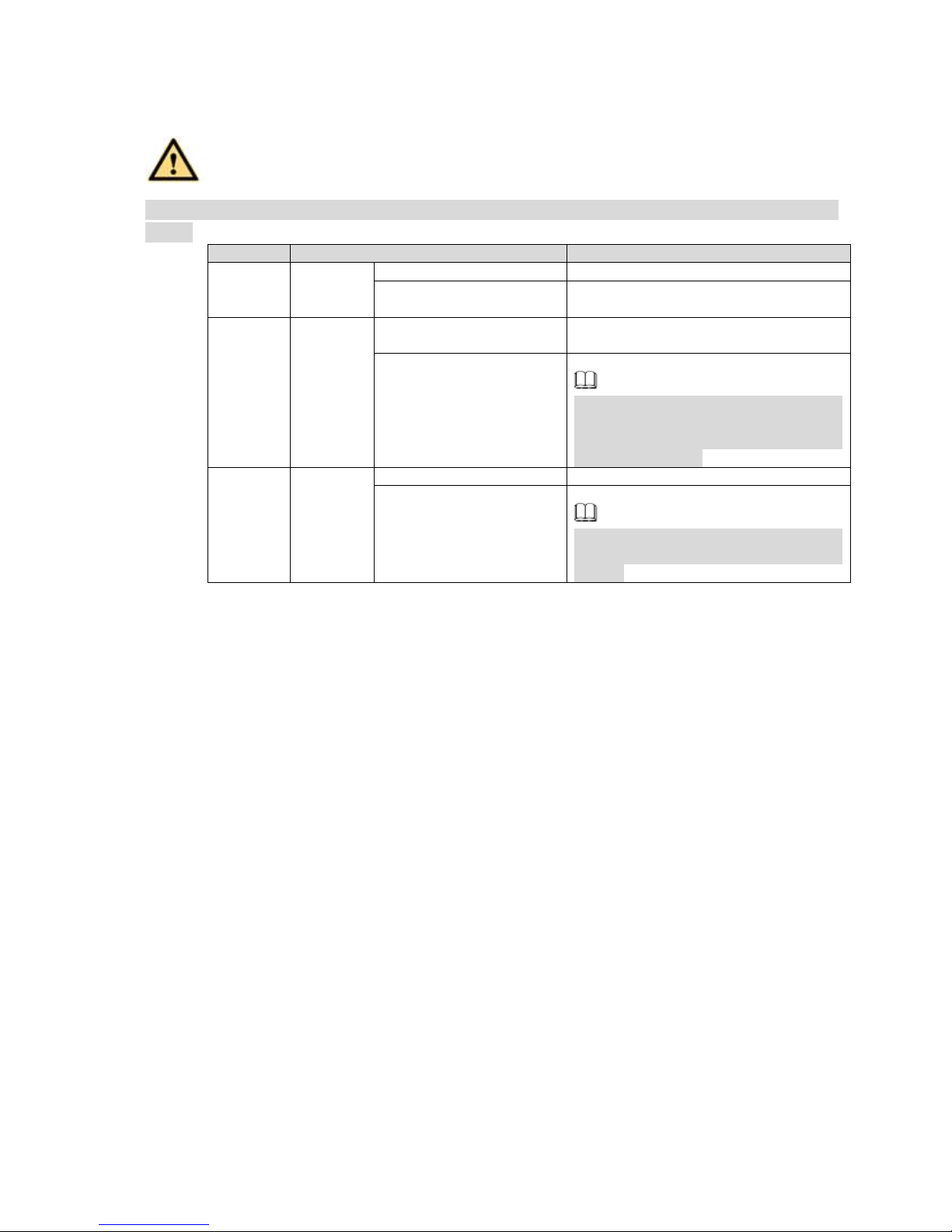
SN
Name
Contents
1
Whole
package
Appearance
There is any visible damage or not.
Package
There is any accidental clash during
transportation or not.
2
Front
panel and
rear
panel
The model on the front
panel
Check the model with the purchase
order.
The label on the rear
panel.
It is neat and clean or not.
Note
Do not tear off, or discard the label.
Usually we need you to represent the
serial number when we provide the
service after sales.
3
Case
Appearance
There is any visible damage or not.
Check the data cable,
power cable, fan cable,
main board and etc.
Check the connection is secure or not.
Note
Contact your local retailer or our
service engineer if the connection is
loosen.
Page 7
2
2 HDD Installation
DANGER
Shut down the device and then unplug the power cable before you open the case to
replace the HDD!
All figures listed below for reference only!
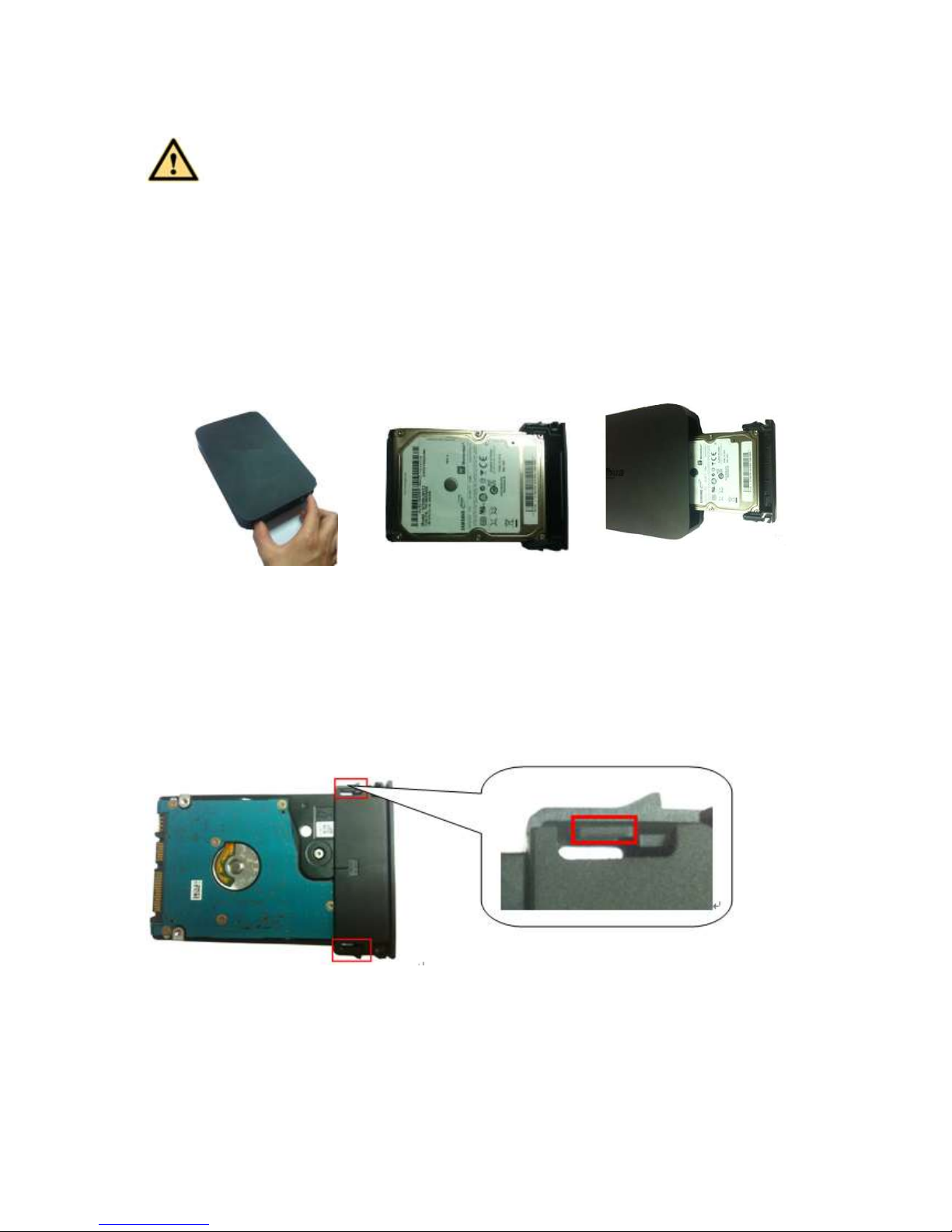
2.1 SMART BOX
Please make sure the metal surface of the HDD is facing up when you are installing!
This series product has only one 2.5-inch SATA HDD.
Please follow the instructions below to install HDD.
○
1 Draw out the HDD bracket
○
2 Make sure the HDD metal
surface is facing up and then put
the HDD into the bracket
horizontally. After the HDD is in
the proper position, the columns
on the two sides can lock the
screw holes of the HDD to secure
it.
○
3 Put the HDD into the
device.
When you remove the HDD, please refer to the following figure to pull the spring up and then remove the
HDD.
2.2 SMART 1U
For the first time to install, please check the HDD has been installed or not.
Refer to the user manual for HDD space information and recommended HDD brand. Please use HDD of
7200rpm or higher. Usually we do not recommend the PC HDD.
Page 8
3
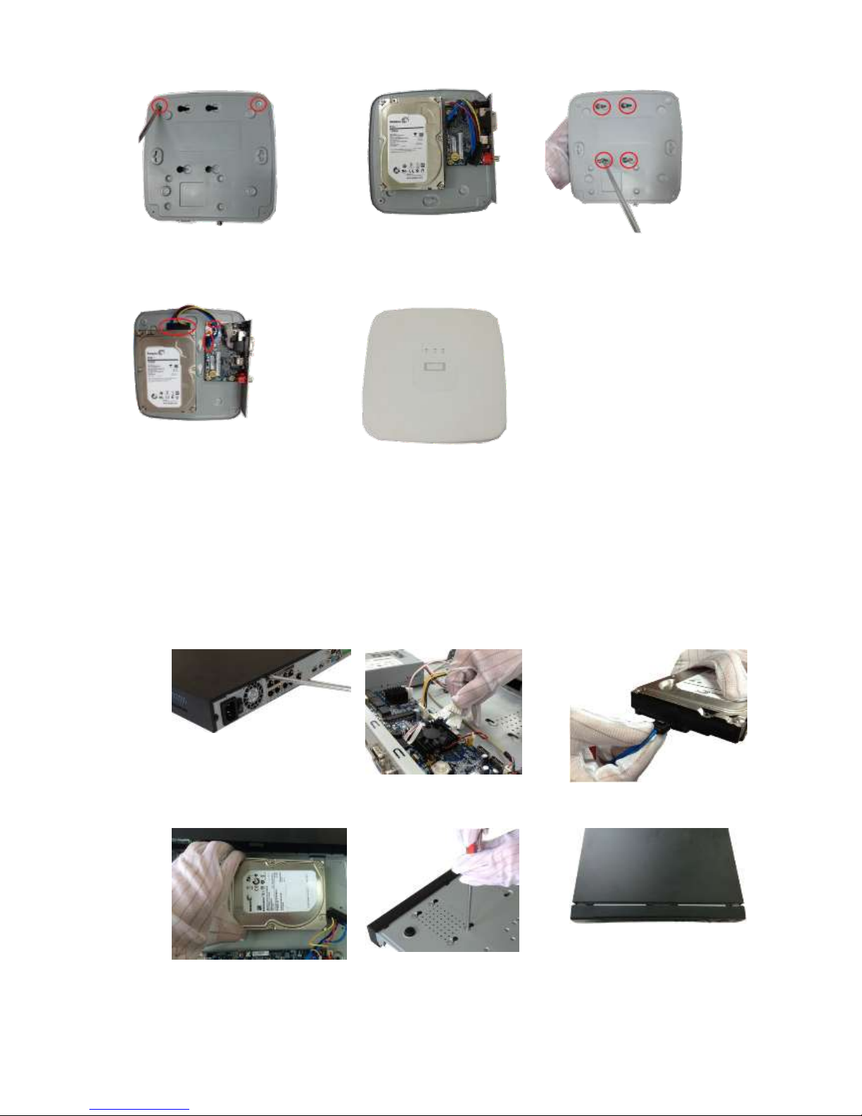
○
1 . Loosen the screws of the bottom of
the chassis.
○
2 Place the HDD in
accordance with the four holes
in the bottom.
○
3 Turn the device upside
down and then secure the
screws firmly.
○
4 Connect the HDD cable and power
cable to the HDD and the mainboard
respectively.
○
5 Put the cover back and then
fix the screws of the rear panel.
The installation is complete.
2.3 MINI 1U, COMPACT 1U, 1U
For the first time to install, please check the HDD has been installed or not.
Refer to the user manual for HDD space information and recommended HDD brand. Please use HDD of
7200rpm or higher. Usually we do not recommend the PC HDD.
① Loosen the screws of the
upper cover and side panel.
② Connect the one end of the
HDD data cable and the power
cable to the mainboard.
③ Connect the other end of the
HDD data cable and the power
cable to the HDD.
④ Place the HDD in accordance
with the four holes on the bottom
of the chassis.
⑤ Turn the device upside down; fix
the screws to secure the HDD on
the bottom of the chassis.
⑥ Put the cover in accordance
with the clip and then fix the
screws on the rear panel and
side panel.
Page 9

4
3 Rear Panel
Follow figures listed here for reference only. Please refer to the actual product for detailed information.
PoE 接口直连 IPC=PoE port to Connect to Network Camera
以太网口=Ethernet Port
电源输入接口=Power Input Port
USB 接口=USB Port
HDMI 高清接口=HDMI Port
VGA 接口=VGA Port
For SMART BOX series product, the front panel is shown as in Figure 3-1.
Figure 3-1
For SMART 1U series product, the front panel is shown as in Figure 3-2.
USB 接口=USB Port
语音对讲输入接口=Audio Talk Input/Output Port
音频输出接口=Audio Output Port
接地=GND
HDMI 高清接口=HDMI Port
VGA 接口=VGA Port
以太网口=Ethernet Port
电源输入接口=Power Input Port
Figure 3-2
For mini 1U, compact 1U series product, the front panel is shown as in Figure 3-3.
USB 接口=USB Port
以太网口=Ethernet Port
Page 10

5
电源输入接口=Power Input Port
HDMI 高清接口=HDMI Port
VGA 接口=VGA Port
接地=GND
Figure 3-3
For 1U series product, the front panel is shown as in Figure 4-4
电源输入接口=Power Input Port
电源开关=Power on-off Button
VGA 接口=VGA Port
以太网口=Ethernet Port
PoE 接口直连 IPC=PoE port to Connect to Network Camera
音频输出接口=Audio Output Port
RS232 接口=RS232 Port
报警输入输出接口=Alarm Input/Output Port
接地=GND
Figure 3-4
Note
Please check the icon on the rear panel carefully. Please refer to the actual product for detailed
information.
If the icon is , it inputs DC 12V power. If the icon is , it inputs the DC 48V power.
Page 11

6
The 4PoE series product supports 48V 50W total power. The 8PoE series products supports 48V
120W total power.
Page 12

7
4 GUI Operation
Note
Slight difference may be found on the user interface. All figures listed below for reference only.
4.1 Boot up
DANGER
Before the boot up, please make sure:
For device security, please connect the NVR to the power adapter first and then connect the
device to the power socket.
The rated input voltage matches the device power on-off button. Please make sure the power
wire connection is OK. Then click the power on-off button.
Always use the stable current, if necessary UPS is a best alternative measure.
Please follow the steps listed below to boot up the device.
Step 1 Connect the device to the monitor and then connect a mouse.
Step 2 Connect power cable.
Step 3 Click the power button at the front or rear panel and then boot up the device. After device booted
up, the system is in multiple-channel display mode by default.
4.2 Device Initialization
If it is your first time to use the device, please set a login password of admin (system default user).
Note
For your device safety, please keep your login password of admin well after the initialization steps, and
change the password regularly.
Please follow the steps listed below.
Step 1 Boot up NVR.
Device displays device initialization interface. See Figure 4-1.
Page 13

8
Figure 4-1
Step 2 Set login password of admin.
User name: The default user name is admin.
Password/confirm password: The password ranges from 8 to 32 digitals. It can contain letters,
numbers and special characters (excluding “'”,“"”,“;”,“:”,“&”) . The password shall contain at least
two categories. Usually we recommend the strong password.
Prompt question: If you set the prompt question here. On the login interface, click , device can
display the corresponding prompt question for you to remind the password.
WARNING
STRONG PASSWORD RECOMMENDED-For your device own safety, please create a
strong password of your own choosing. We also recommend you change your password
periodically especially in the high security system.
Step 3 Click Next, device goes to the following interface. See Figure 4-2.
Page 14

9
Figure 4-2
Step 4 Set unlock pattern.
After set unlock pattern, device goes to password protection interrface. See Figure 4-3.
Note
Device adopts unlock pattern to login by default if you have set pattern here. If there is no
unlock pattern, please input the password to login.
Click Skip if there is no need to set unlock pattern.
Page 15

10
Figure 4-3
Step 5 Set security questions.
Note
After setting the security questions here, you can use the email you input here or answer the
security questions to reset admin password. Refer to user’s manual for detailed information.
Cancel the email or security questions box and then click Next button to skip this step.
Email: Input an email address for reset password purpose. In case you forgot password in the
future, input the security code you got on the assigned email to reset the password of admin. If
you have not input email here or you need to update the email information, please go to the main
menu->Setting->System->Account to set. Refer to user’s manual for detailed information.
Security question: Set security questions and corresponding answers. Properly answer the
questions to reset admin password. In case you have not input security question here or you
need to update the security question information, please go to the main menu->Setting>System->Account->Security question to set. Refer to user’s manual for detailed information.
Note
If you want to reset password by answering security questions, please go to the local menu
interface.
Step 6 Click OK to complete the device initialization setup.
Device goes to startup wizard interface. Refer to user’s manual for Startup wizard detailed
information.
Page 16

11
4.3 Change IP Address
Note
Different series products have different Ethernet adapter amount and type. Please refer to the actual
product.
From Main menu->Setting->Network->TCP/IP, enter TCP/IP interface. See Figure 4-4.
It is to change default IP address (192.168.1.108).
Figure 4-4
4.4 Camera Registration
From Main menu->Setting->Camera->Registration, enter Registration interface. Or on the preview
interface, right click mouse and then select Camera Registration. Enter the Registration interface. See
Figure 4-5.
Click Device search and then double click the searched device on the list, or check the box before the
searched device name and then click Add button. Click OK to complete the add operation.
Page 17

12
Figure 4-5
4.5 Schedule
From Main menu->Setting->Storage->Schedule, enter schedule interface. See Figure 4-6.
After device first booted up, all channels are record continuously by default. Device supports customized
record period and record type.
Page 18

13
Figure 4-6
4.6 Playback
From Main menu->Search, or on the preview interface right click mouse and then select search item, enter
the following interface. See Figure 4-7.
It is to search and playback the video record file or image. Please refer to the user’s manual for detailed
information.
Page 19

14
Figure 4-7
4.7 Shut down
From Main menu->shut down, enter the shutdown interface. Click Shut down.
Page 20

15
5 Web Operation
If it is your first time to login the device, please initialize your device first. Refer to the user’s
manual for detailed information.
5.1 Login
Step 1 Open the browser and input NVR address in the address column. Click Enter button.
Enter login interface. See Figure 5-1.
Figure 5-1
Step 2 Input user name and password.
Note
Device default user name is admin. The password is that you set during initialization process. For
your device safety, please change the admin password regularlay and keep it well.
In case you forgot passowrd, click Forgot password to reset. Refer to the user’s manual for
detailed informaiton.
Step 3 Click Login.
Enter preview interface. See Figure 5-2. Refer to the user’s manual for detailed information.
Note
Click Install the plug-in to install if it is your first time to login the WEB.
Page 21

16
Figure 5-2
Page 22

17
6 P2P
Step 1 Use cell phone to scan the client QR code and download the APP. See Figure 6-1.
Note
There are two ways to get QR code.
Refer to the device package box to get the cell phone client QR code.
Login the device local menu, and from main menu->Setting->Network->P2P, or login the WEB,
from Setup->Network->TCP/IP->P2P to get the client QR code and the device SN QR code.
Figure 6-1
Step 2 After installation, run the APP and then select Live preview to go to the main interface. Add the
device via the cell phone.
1) Tap and then tap Device Manager. See Figure 6-2.
Figure 6-2
Page 23

18
2) Tap P2P to add the device. See Figure 6-3.
Figure 6-3
3) Scan the device label or the device SN on the device local menu to add the device. See
Figure 6-4.
Figure 6-4
a) After scan, you can view the product SN. Click the Start live preview button, now you can see live
view on the cell phone. See Figure 6-5.
Page 24

19
Figure 6-5
For detailed operation information, please refer to the User’s Manual.
Note
Slight difference may be found in user interface.
All the designs and software here are subject to change without prior written notice.
All trademarks and registered trademarks are the properties of their respective owners.
If there is any uncertainty or controversy, please refer to the final explanation of us.
Please visit our website or contact your local service engineer for more information.
 Loading...