

Page 1

AI Network Video Recorder
User’s Manual
V1.0.3
ZHEJIANG DAHUA VISION TECHNOLOGY CO., LTD.
Page 2
General
Series
Model
NVR4
NVR4832-I; NVR4432-I, NVR4416-16P-I; NVR4216-16P-I, NVR4216-I,
NVR4208-8P-I.
NVR5
NVR5864-I; NVR5832-I; NVR5432-16P-I; NVR5216-16P-I, NVR5216-8P-I.
Signal Words
Meaning
Indicates a potential risk which, if not avoided, may result in
property damage, data loss, lower performance, or unpredictable
result.
Electrostatic Sensitive Devices.
Indicates a device that is sensitive to electrostatic discharge.
Provides methods to help you solve a problem or save you time.
Provides additional information as the emphasis and supplement
to the text.
This user’s manual (hereinafter referred to be "the Manual") introduces the installation, functions
and operations of the AI Network Video Recorder (AI NVR) devices (hereinafter referred to be
"the Device").
Models
Safety Instructions
The following categorized signal words with defined meaning might appear in the Manual.
Foreword
Revision History
Foreword I
Page 3

Version
Revision Content
Release Time
V1.0.3
1. New GUI baseline, replaces all interfaces.
2. Adds AI functions.
July 2019
V1.0.2
Update the description of rear panel.
May 2019
V1.0.1
1. Adds NVR 5216-16P-I and NVR5216-8P-I.
Update relevant info.
2. Updates icons on the rear panel.
3. Adds video metadata function and
non-motor vehicle detection function.
September 2018
V1.0.0
First release.
—
Privacy Protection Notice
As the device user or data controller, you might collect personal data of others such as face,
fingerprints, car plate number, Email address, phone number, GPS and so on. You need to be in
compliance with the local privacy protection laws and regulations to protect the legitimate rights
and interests of other people by implementing measures including but not limited to: providing
clear and visible identification to inform data subject the existence of surveillance area and
providing related contact.
About the Manual
The Manual is for reference only. If there is inconsistency between the manual and the
actual product, the actual product shall prevail.
We are not liable for any loss caused by the operations that do not comply with the manual.
The manual would be updated according to the latest laws and regulations of related
regions. For detailed information, see the paper manual, CD-ROM, QR code or our official
website. If there is inconsistency between paper manual and the electronic version, the
electronic version shall prevail.
All the designs and software are subject to change without prior written notice. The product
updates might cause some differences between the actual product and the manual. Please
contact the customer service for the latest program and supplementary documentation.
There still might be deviation in technical data, functions and operations description, or
errors in print. If there is any doubt or dispute, please refer to our final explanation.
Upgrade the reader software or try other mainstream reader software if the manual (in PDF
format) cannot be opened.
All trademarks, registered trademarks and the company names in the manual are the
properties of their respective owners.
Please visit our website, contact the supplier or customer service if there is any problem
occurred when using the device.
If there is any uncertainty or controversy, please refer to our final explanation.
Foreword II
Page 4

Important Safeguards and Warnings
The following description is the correct application method of the device. Read the manual
carefully before use to prevent danger and property loss. Strictly conform to the manual during
application and keep it properly after reading.
Operating Requirement
Install the PoE front-end device indoors.
The device does not support wall mount.
Do not place and install the device in an area exposed to direct sunlight or near heat
generating device.
Do not install the device in a humid, dusty or fuliginous area.
Keep its horizontal installation, or install it at stable places, and prevent it from falling.
Do not drip or splash liquids onto the device; do not put on the device anything filled with
liquids, in order to prevent liquids from flowing into the device.
Install the device at well-ventilated places; do not block its ventilation opening.
Use the device only within rated input and output range.
Do not dismantle the device arbitrarily.
Transport, use and store the device within allowed humidity and temperature range.
Power Requirement
Make sure to use the designated battery type. Otherwise there may be explosion risk.
Make sure to use batteries according to requirements. Otherwise, it may result in fire,
explosion or burning risks of batteries!
To replace batteries, only the same type of batteries can be used.
Make sure to dispose the exhausted batteries according to the instructions.
The product shall use electric wires (power wires) recommended by this area, which shall
be used within its rated specification.
Make sure to use standard power adapter matched with this device. Otherwise, the user
shall undertake resulting personnel injuries or device damages.
Use power supply that meets SELV (safety extra low voltage) requirements, and supply
power with rated voltage that conforms to Limited Power Source in IEC60950-1. For
specific power supply requirements, please refer to device labels.
Products with category I structure shall be connected to grid power output socket, which is
equipped with protective grounding.
Important Safeguards and Warnings III
Page 5

Appliance coupler is a disconnecting device. During normal use, please keep an angle that
facilitates operation.
Important Safeguards and Warnings IV
Page 6

Table of Contents
Foreword ....................................................................................................................................................... I
Important Safeguards and Warnings .......................................................................................................... III
1 Features .............................................................................................................................................................. 1
1.1 Overview ..................................................................................................................................................... 1
1.2 Features ...................................................................................................................................................... 1
2 Front Panel and Rear Panel ............................................................................................................................ 5
2.1 Front Panel ................................................................................................................................................. 5
2.2 Rear Panel ................................................................................................................................................. 5
2.2.1 NVR58-I/4832-I Series..................................................................................................................... 5
2.2.2 NVR54-16P-I/4416-16P-I/4432-I Series ....................................................................................... 7
2.2.3 NVR52-16P-I/52-8P-I/42-16P-I Series .......................................................................................... 9
2.2.4 NVR4208-8P-I ................................................................................................................................. 11
2.2.5 NVR4216-I Series .......................................................................................................................... 13
2.3 Alarm Connection .................................................................................................................................... 14
2.3.1 Alarm Port ........................................................................................................................................ 14
2.3.2 Alarm Input Port .............................................................................................................................. 15
2.3.3 Alarm Output Port ........................................................................................................................... 16
2.3.4 Alarm Relay Specifications ........................................................................................................... 16
2.4 Bidirectional talk ...................................................................................................................................... 16
2.4.1 Device-end to PC-end ................................................................................................................... 16
2.4.2 PC-end to the device-end ............................................................................................................. 17
2.5 Mouse Operation ..................................................................................................................................... 17
2.6 Remote Control ....................................................................................................................................... 18
3 Device Installation ........................................................................................................................................... 21
3.1 Device Installation Diagrams ................................................................................................................. 21
3.2 Check Unpacked NVR ............................................................................................................................ 21
3.3 About Front Panel and Rear Panel....................................................................................................... 22
3.4 HDD Installation ....................................................................................................................................... 22
3.4.1 NVR58-I/54-16P-I/4832-I/4416-16P-I/4432-I Series ................................................................. 22
3.4.2 NVR52-16P-I/52-8P-I/4216-16P-I/4208-8P-I/4216-I Series ..................................................... 25
3.5 CD-ROM Installation ............................................................................................................................... 27
3.6 Connection Sample ................................................................................................................................. 28
3.6.1 NVR58-I/4832-I Series................................................................................................................... 28
3.6.2 NVR54-16P-I/4416-16P-I/4432-I Series ..................................................................................... 29
3.6.3 NVR52-16P-I/52-8P-I/4216-16P-I/4208-8P-I/4216-I Series ..................................................... 29
4 Local Basic Operations .................................................................................................................................. 31
4.1 Getting Started ......................................................................................................................................... 31
4.1.1 Boot up ............................................................................................................................................. 31
4.1.2 Device Initialization ........................................................................................................................ 31
4.1.3 Reset Password .............................................................................................................................. 35
Table of Contents I
Page 7

4.1.4 Quick Settings ................................................................................................................................. 42
4.2 Camera ..................................................................................................................................................... 69
4.2.1 Connection ...................................................................................................................................... 69
4.2.2 Remote Device Initialization ......................................................................................................... 73
4.2.3 Short-Cut Menu to Register Camera ........................................................................................... 77
4.2.4 Image ............................................................................................................................................... 77
4.2.5 Encode ............................................................................................................................................. 80
4.2.6 Channel Name ................................................................................................................................ 84
4.2.7 Remote Upgrade ............................................................................................................................ 85
4.2.8 Remote Device Info ........................................................................................................................ 86
4.3 Live View .................................................................................................................................................. 87
4.3.1 Preview ............................................................................................................................................ 87
4.3.2 Navigation bar ................................................................................................................................. 88
4.3.3 Preview Control Interface .............................................................................................................. 91
4.3.4 Sequence ......................................................................................................................................... 96
4.3.5 Fisheye (Optional) .......................................................................................................................... 99
4.3.6 Test Temperature .......................................................................................................................... 101
4.3.7 AI Preview Mode .......................................................................................................................... 102
4.4 PTZ .......................................................................................................................................................... 104
4.4.1 PTZ Settings.................................................................................................................................. 105
4.4.2 PTZ Control ................................................................................................................................... 107
4.4.3 Configuring PTZ Functions ......................................................................................................... 109
4.4.4 Calling PTZ Functions ................................................................................................................. 111
4.5 Record File ............................................................................................................................................. 112
4.6 Playback and Search ............................................................................................................................ 112
4.6.1 Instant Playback ........................................................................................................................... 113
4.6.2 Search Interface ........................................................................................................................... 113
4.6.3 Smart Search Playback ............................................................................................................... 118
4.6.4 Mark Playback .............................................................................................................................. 119
4.6.5 Playback Image ............................................................................................................................ 120
4.6.6 Splice Playback ............................................................................................................................. 120
4.6.7 File List ........................................................................................................................................... 121
4.6.8 Other Aux Functions ................................................................................................................... 122
4.7 AI .............................................................................................................................................................. 123
4.7.1 AI Search ....................................................................................................................................... 123
4.7.2 Parameters .................................................................................................................................... 136
4.7.3 Database ....................................................................................................................................... 182
4.8 Event Manager ...................................................................................................................................... 190
4.8.1 Alarm Info ...................................................................................................................................... 190
4.8.2 Alarm Status .................................................................................................................................. 191
4.8.3 Alarm Input .................................................................................................................................... 192
4.8.4 Alarm Control ................................................................................................................................ 195
4.8.5 Video Detection ............................................................................................................................ 196
4.8.6 Audio Detect .................................................................................................................................. 204
4.8.7 Thermal Alarm .............................................................................................................................. 207
4.8.8 Abnormality.................................................................................................................................... 210
Table of Contents II
Page 8

4.9 POS ......................................................................................................................................................... 215
4.9.1 Search ............................................................................................................................................ 215
4.9.2 Settings .......................................................................................................................................... 216
4.10 Operation and Maintenance ................................................................................................................ 219
4.10.1 Log .................................................................................................................................................. 219
4.10.2 System ........................................................................................................................................... 221
4.10.3 Network .......................................................................................................................................... 224
4.10.4 Maintenance and Management .................................................................................................. 227
4.11 File Backup ............................................................................................................................................. 235
4.12 Network ................................................................................................................................................... 236
4.12.1 TCP/IP ............................................................................................................................................ 236
4.12.2 Port ................................................................................................................................................. 238
4.12.3 PPPoE ............................................................................................................................................ 239
4.12.4 DDNS ............................................................................................................................................. 240
4.12.5 UPnP .............................................................................................................................................. 242
4.12.6 Email ............................................................................................................................................... 244
4.12.7 SNMP ............................................................................................................................................. 246
4.12.8 Multicast ......................................................................................................................................... 248
4.12.9 Alarm Centre ................................................................................................................................. 249
4.12.10 Register .......................................................................................................................................... 250
4.12.11 P2P ................................................................................................................................................. 251
4.12.12 802.1X ............................................................................................................................................ 253
4.13 Storage ................................................................................................................................................... 255
4.13.1 Basic ............................................................................................................................................... 255
4.13.2 Schedule ........................................................................................................................................ 256
4.13.3 HDD ................................................................................................................................................ 256
4.13.4 Record Control .............................................................................................................................. 257
4.13.5 Advance (HDD Group)................................................................................................................. 257
4.13.6 HDD Detect ................................................................................................................................... 258
4.13.7 RAID ............................................................................................................................................... 261
4.13.8 Record Estimate ........................................................................................................................... 266
4.13.9 FTP ................................................................................................................................................. 268
4.14 System .................................................................................................................................................... 270
4.14.1 General .......................................................................................................................................... 270
4.14.2 RS232 ............................................................................................................................................ 270
4.14.3 Security .......................................................................................................................................... 272
4.15 Account ................................................................................................................................................... 275
4.15.1 User ................................................................................................................................................ 275
4.15.2 Group ............................................................................................................................................. 278
4.15.3 Reset Password ............................................................................................................................ 279
4.15.4 ONVIF User ................................................................................................................................... 280
4.16 Output and Display................................................................................................................................ 282
4.16.1 Display ........................................................................................................................................... 282
4.16.2 Tour ................................................................................................................................................. 283
4.16.3 Customized Display ..................................................................................................................... 285
4.17 Audio ....................................................................................................................................................... 287
Table of Contents III
Page 9

4.17.1 File Manage ................................................................................................................................... 287
4.17.2 Schedule ........................................................................................................................................ 289
4.17.3 Broadcast ....................................................................................................................................... 290
4.18 USB Device Auto Pop-up ..................................................................................................................... 292
4.19 Shutdown ................................................................................................................................................ 292
5 Web Operations ............................................................................................................................................. 296
5.1 Network Connection.............................................................................................................................. 296
5.2 Web Login .............................................................................................................................................. 296
5.3 Reset Password .................................................................................................................................... 297
5.4 Web Main Menu .................................................................................................................................... 299
6 Glossary .......................................................................................................................................................... 302
7 FAQ ................................................................................................................................................................. 303
Appendix 1 HDD Capacity Calculation .................................................................................................... 307
Appendix 2 Compatible Network Camera List ......................................................................................... 308
Appendix 3 Cybersecurity Recommendations ......................................................................................... 312
Table of Contents IV
Page 10

1.1 Overview
This series NVR is a high performance network video recorder. This series product support local
preview, multiple-window display, recorded file local storage, remote control and mouse shortcut
menu operation, and remote management and control function.
This series product supports center storage, front-end storage and client-end storage. The
monitor zone in the front-end can be set in anywhere. Working with other front-end devices such
as IPC, NVS, this series product can establish a strong surveillance network via the CMS. In the
network system, there is only one network cable from the monitor center to the monitor zone in
the whole network. There is no audio/video cable from the monitor center to the monitor zone.
The whole project is featuring of simple connection, low-cost, low maintenance work.
This series NVR can be widely used in many areas such as public security, water conservancy,
transportation and education.
1.2 Features
1 Features
AI Functions
Different models have different AI functions. The actual product shall prevail.
Face detection. It includes front-end smart detection and rear-end smart detection.
Face recognition. It enables users to compare the detected faces with the images in the
face library at real time.
Human body detection. System activates alarm actions once human body is detected.
People counting. It can effectively count the population number and flow direction.
Heat map. It can monitor the active objects in a specific area.
Automatic number plate recognition (ANPR). It can effectively monitor the passing vehicles.
Smart Playback
IVS playback. It can screen out and replay the records meeting the set rules.
Face detection playback. It can screen out and replay the records with human faces.
Face recognition playback. It can compare the face information in the video with the
information in the database and replay the corresponding records.
ANPR playback. It can screen out the record with a specific car plate number or all the
records with car plate numbers.
Human body detection playback. It can screen out and replay the records with specific
human bodies.
Features 1
Page 11

Smart Search. It includes smart functions such as searching by attribute and searching by
image to enable users to get target records quickly.
Cloud Upgrade
For the NVR connected to the Internet, it supports application online upgrade.
Real-Time Surveillance
VGA, HDMI port. Connect to monitor to realize real-time surveillance. Some series support
TV/VGA/HDMI output at the same time.
Short-cut menu for preview.
Support multiple popular PTZ decoder control protocols. Support preset, tour and pattern.
Playback
Support independent real-time recording for each channel. At the same time it supports
functions such as smart search, forward play, network monitor, record search and
download.
Support various playback modes: slow play, fast play, backward play and frame-by-frame
play.
Support time title overlay so that you can view the event accurate occurred time.
Support specified zone enlargement.
User Management
Each group has an authority collection which can be edited freely and belongs to the total
authority collection. The authorities of any user in the group cannot be larger than that of the
group.
Storage
Via corresponding settings (such as alarm settings and schedule settings), you can back up
related audio/video data in the network video recorder.
You can take records via the Web and the record files are saved on the PC in which the
client locates.
Alarm
Respond to external alarm simultaneously (within 200MS). Based on user’s pre-defined
relay settings, the system can process the alarm input correctly and sends user screen or
voice prompts (supporting pre-recorded audio).
Features 2
Page 12

Support settings of the central alarm server, so that the system can automatically notify
users of the alarm information. Alarm input can be derived from various connected
peripheral devices.
Alert you of alarm information via email.
Network Surveillance
Send audio/video data compressed by IPC or NVS to client-ends through the network, and
then the data will be decompressed and displayed.
Support max 128 connections at the same time.
Transmit audio/video data by protocols such as HTTP, TCP, UDP, MULTICAST and
RTP/RTCP.
Transmit some alarm data or alarm info by SNMP.
Support WEB access in WAN/LAN.
Window Split
Adopt video compression and digital processing to display several windows in one monitor.
Support 1/4/8/9/16/ 25/36 window split in preview and 1/4/9/16 window split in playback.
Record
Support regular record, motion record, alarm record and smart record. Save the recorded files in
the HDD, USB device, client-end PC or network storage server and you can search or playback
the saved files at the local-end or via the Web/USB devices.
Backup
Support network backup and USB record backup. You can back up the record files in devices
such as network storage server, peripheral USB2.0 device and burner.
Network Management
Supervise NVR configuration and control power via Ethernet.
Support Web management.
Peripheral Equipment Management
Support peripheral device control and you can freely set the control protocol and connection
Support transparent data transmission such as RS232 (RS-422) and RS485 (RS-485).
Auxiliary
port.
Features 3
Page 13

Support switch between NTSC and PAL.
Support real-time display of system resources information and running status.
Support log record.
Local GUI output. Shortcut menu operation with the mouse.
IR control function (for some series only). Shortcut menu operation with remote control.
Support to play the video/audio files from remote IPC or NVS.
For description of other function, see the following contents.
Features 4
Page 14
2 Front Panel and Rear Panel
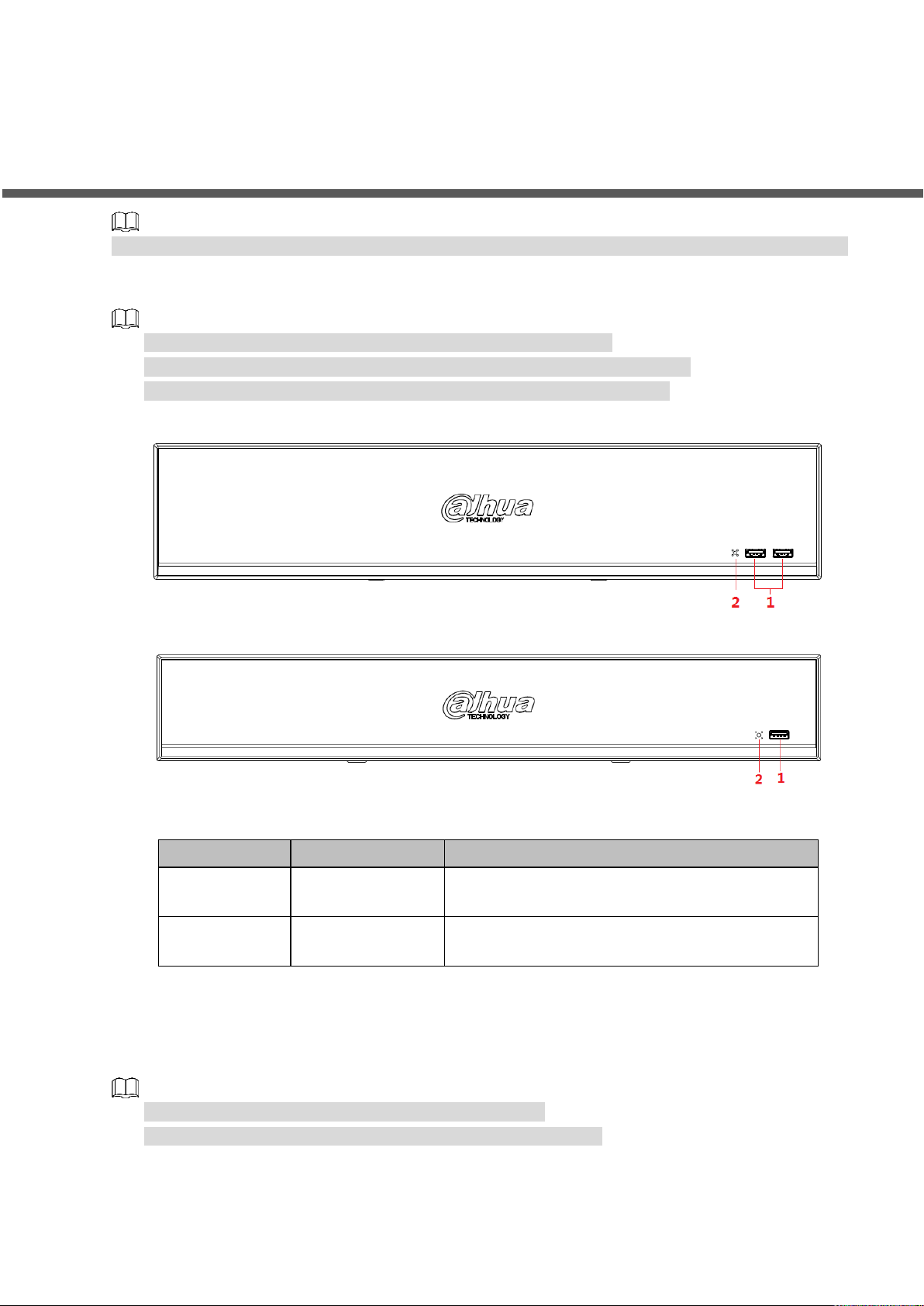
No.
Port Name
Function
1
USB port
Connects to the external devices such as
keyboard, mouse, and USB storage device.
2
IR indicator
Receive signals from the remote control.
The following front panel and rear panel figures are for reference only. The actual product shall prevail.
2.1 Front Panel
Figure 2-1 takes NVR5864-I and NVR5832-I series as examples.
Figure 2-2 takes NVR5432-16P-I/5216-16P-I/5216-8P-I series as examples.
These two figures are for reference only. The actual product shall prevail.
Figure 2-1
Figure 2-2
Table 2-1
2.2 Rear Panel
2.2.1 NVR58-I/4832-I Series
The figure takes NVR5864-I/5832-I series as examples.
The figure is for reference only. The actual product shall prevail.
Front Panel and Rear Panel 5
Page 15
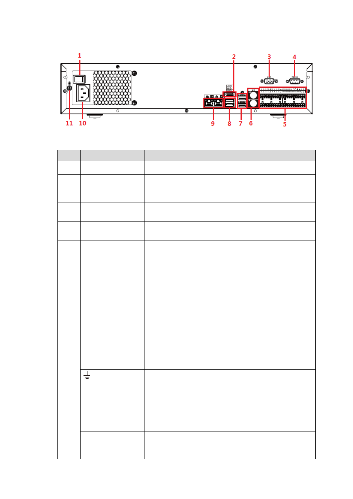
Figure 2-3
No.
Port Name
Function
1
Power button
Turns on/off the NVR.
2
eSATA port
External SATA port. It can connect device with SATA port.
You need to jump the HDD when there is peripherally
connected HDD.
3
VGA port
VGA video output port. Output analog video signal. It can
connect to the monitor to view analog video.
4
RS232 port
It is for general COM debugging to configure IP address and
transfer transparent COM data.
5
Alarm input port
(1-16)
There are four groups: 1-4, 5-8, 9-12 and 13-16.
They receive signals from external alarm source. Alarm
input includes two types; NO (normal open) and NC
(normal close).
When your alarm input device is using external power,
make sure the device and the NVR have the same
GND.
Alarm output port
(NO1-NO5, C1-C5,
NC5)
Five groups of alarm output ports (Group 1: NO1-C1,
Group 2: NO2-C2, Group 3: NO3-C3, Group 4:
NO4-C4, Group 5: NO5, C5, NC5).Output alarm signal
to the external alarm device. Make sure power supply is
available for the external alarm device.
NO: Normal open alarm output port.
C: Alarm output public end.
NC: Normal close alarm output port.
GND. Alarm input ground port.
RS485 port (A, B)
RS485_A port. Control cable A of the 485 device. It
connects external devices such as speed dome and
PTZ.
RS485_B port. Control cable B of the 485 device. It
connects external devices such as speed dome and
PTZ.
CTRL
Controllable 12V power output. It is to control the on-off
alarm relay output. It can be used to control the device
alarm output. At the same time, it can also be used as the
Table 2-2
Front Panel and Rear Panel 6
Page 16
No.
Port Name
Function
power input source of some devices such as alarm detector.
+12V power output port. It can provide power to some
peripheral devices such as camera and alarm device. Make
sure the power supply of peripheral device shall be below
1A.
6
MIC IN
Bidirectional talk input port. It is to receive analog audio
signal from devices such as microphone, sound pickup.
MIC OUT
Audio output port. It is to output analog audio signal to
devices such as sound box.
Bidirectional talk output.
Audio output on 1-window video monitor.
Audio output on 1-window video playback.
7
HDMI port
High definition audio and video signal output port. It
transmits uncompressed high definition video and
multiple-channel audio data to displays with HDMI port. The
two HDMI ports support 2-channel high definition HDMI
output of different sources.
8
USB port
USB3.0 port. Connect to devices such as mouse, USB
storage device and USB burner.
9
Network port
10M/100M/1000Mbps self-adaptive Ethernet port. Connect
to the network cable.
10
Power input port
Input power of 100V-240V and 50Hz-60Hz.
11 GND.
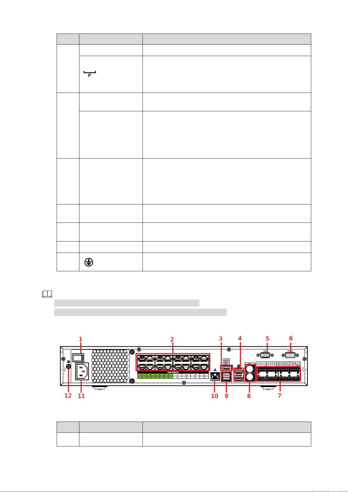
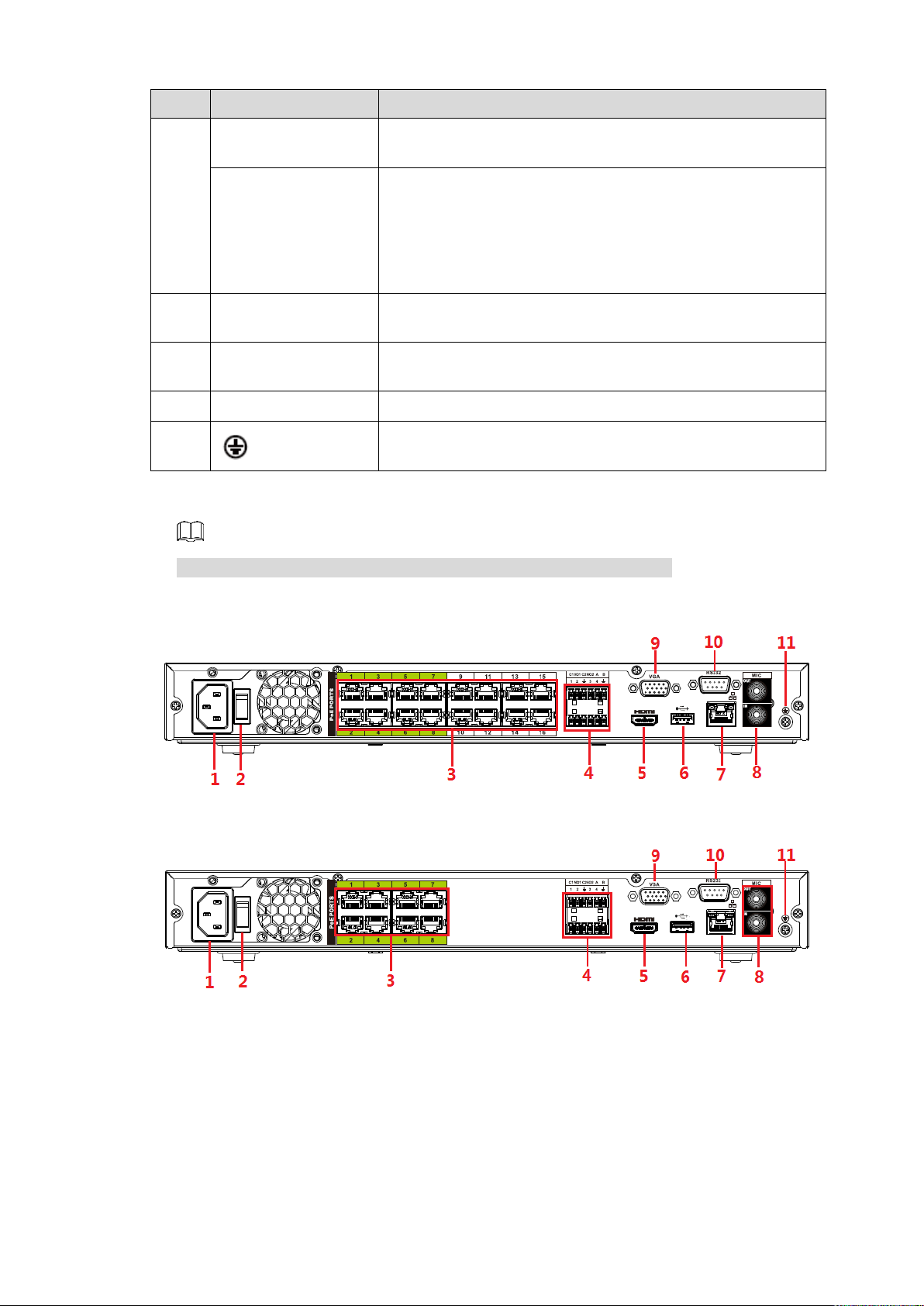
2.2.2 NVR54-16P-I/4416-16P-I/4432-I Series
No.
Port Name
Function
1
Power button
Turns on/off the NVR.
Figure 2-4 takes NVR5432-16P-I series as examples.
The figure is for reference only. The actual product shall prevail.
Figure 2-4
Table 2-3
Front Panel and Rear Panel 7
Page 17

No.
Port Name
Function
2
PoE port
Built-in switch. It can provide power for IPC.
16 PoE ports: 1-8 are ePoE ports (support 300m @
100M. 800m @ 10M). 9-16 are regular PoE ports.
Device with 16 PoEs supports 150W total power.
3
eSATA port
External SATA port. It can connect device with SATA port.
You need to jump the HDD when there is peripherally
connected HDD.
4
HDMI port
High definition audio and video signal output port. It
transmits uncompressed high definition video and
multiple-channel audio data to displays with HDMI port. The
two HDMI ports support 2-channel high definition HDMI
output of different sources.
5
VGA port
VGA video output port. Output analog video signal. It can
connect to the monitor to view analog video.
6
RS232 port
It is for general COM debugging to configure IP address and
transfer transparent COM data.
7
Alarm input port
(1-16)
There are four groups: 1-4, 5-8, 9-12 and 13-16.
They receive signals from external alarm source. Alarm
input includes two types; NO (normal open) and NC
(normal close).
When your alarm input device is using external power,
make sure the device and the NVR have the same
GND.
Alarm output port
(NO1-NO5, C1-C5,
NC5)
Five groups of alarm output ports (Group 1: NO1-C1,
Group 2: NO2-C2, Group 3: NO3-C3, Group 4:
NO4-C4, Group 5: NO5, C5, NC5).Output alarm signal
to the external alarm device. Make sure power supply is
available for the external alarm device.
NO: Normal open alarm output port.
C: Alarm output public end.
NC: Normal close alarm output port.
GND. Alarm input ground port.
RS485 port (A, B)
RS485_A port. Control cable A of the 485 device. It
connects external devices such as speed dome and
PTZ.
RS485_B port. Control cable B of the 485 device. It
connects external devices such as speed dome and
PTZ.
CTRL
Controllable 12V power output. It is to control the on-off
alarm relay output. It can be used to control the device
alarm output. At the same time, it can also be used as the
power input source of some devices such as alarm detector.
+12V power output port. It can provide power to some
peripheral devices such as camera and alarm device. Make
sure the power supply of peripheral device shall be below
1A.
Front Panel and Rear Panel 8
Page 18
No.
Port Name
Function
8
MIC IN
Bidirectional talk input port. It is to receive analog audio
signal from devices such as microphone, sound pickup.
MIC OUT
Audio output port. It is to output analog audio signal to
devices such as sound box.
Bidirectional talk output.
Audio output on 1-window video monitor.
Audio output on 1-window video playback.
9
USB port
USB3.0 port. Connect to devices such as mouse, USB
storage device and USB burner.
10
Network port
10M/100M/1000Mbps self-adaptive Ethernet port. Connect
to the network cable.
11
Power input port
Input power of 100V-240V and 50Hz-60Hz.
12 GND.
2.2.3 NVR52-16P-I/52-8P-I/42-16P-I Series
These figures are for reference only. The actual product shall prevail.
Figure 2-5 NVR5216-16P-I
Figure 2-6 NVR5216-8P-I
Front Panel and Rear Panel 9
Page 19
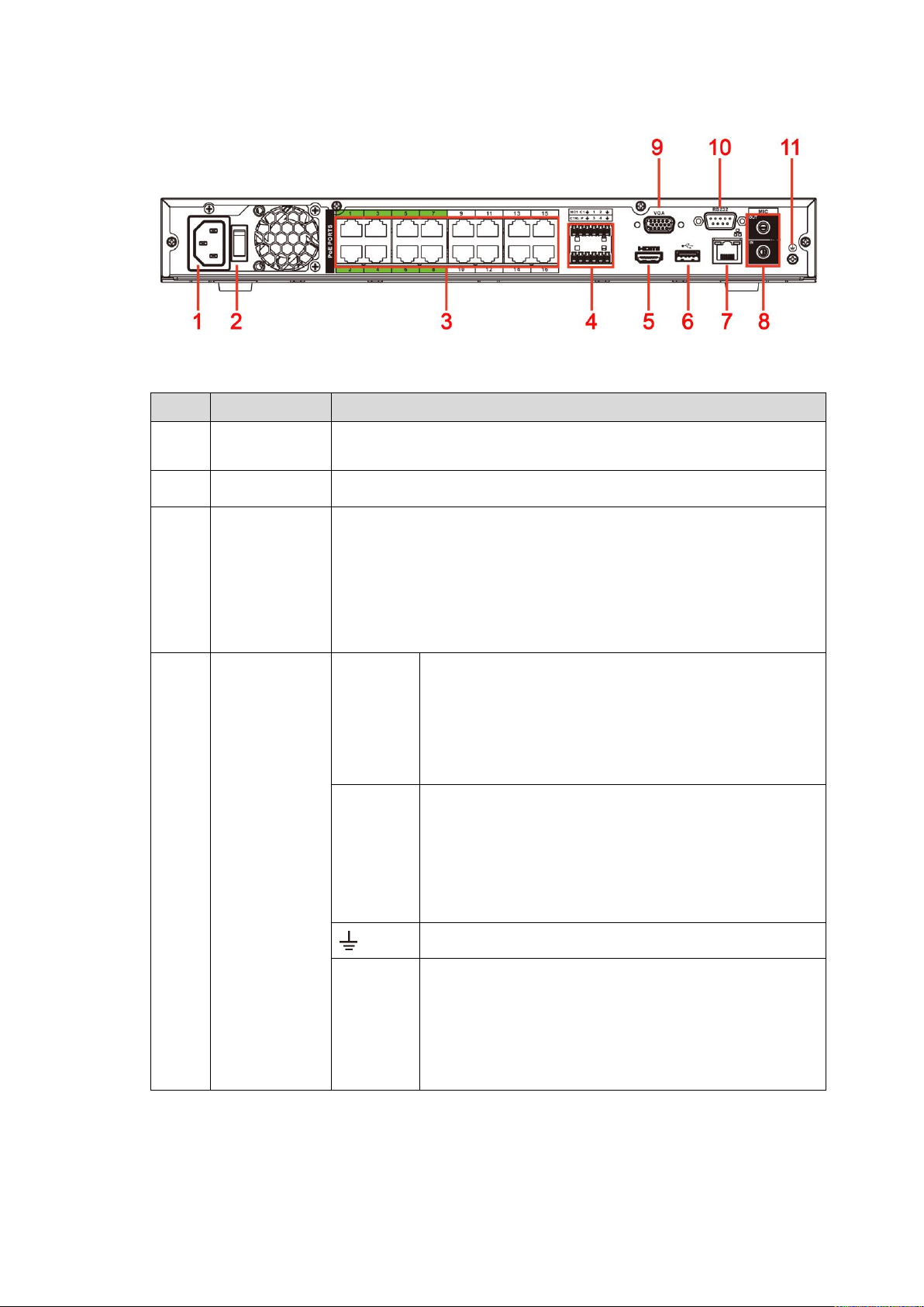
Figure 2-7 NVR4216-16P-I
No.
Port Name
Function
1
Power input
port
Input power of 100V-240V and 50Hz-60Hz.
2
Power button
Turns on/off the NVR.
3
PoE port
Built-in switch. It can provide power for IPC.
16 PoE ports: 1-8 are ePoE ports (support 300m @ 100M. 800m
@ 10M). 9-16 are regular PoE ports. The device supports 150W
total power.
8 PoE ports: 1-8 are ePoE ports (support 300m @ 100M. 800m @
10M). The device supports 48V, 120W total power.
4
Alarm
input/output of
NVR52-16P-I
and 52-8P-I
Alarm
input port
(1-4)
They receive signals from external alarm source.
Alarm input includes two types; NO (normal open)
and NC (normal close).
When your alarm input device is using external
power, make sure the device and the NVR have
the same GND.
Alarm
output
port
(NO1-NO
2, C1-C2)
Two groups of alarm output ports (Group 1:
NO1-C1, Group 2: NO2-C2). Output alarm signal
to the external alarm device. Make sure power
supply is available for the external alarm device.
NO: Normal open alarm output port.
C: Alarm output public end.
GND. Alarm input ground port.
RS485
port (A,
B)
RS485_A port. Control cable A of the 485 device.
It connects external devices such as speed dome
and PTZ.
RS485_B port. Control cable B of the 485 device.
It connects external devices such as speed dome
and PTZ.
Table 2-4
Front Panel and Rear Panel 10
Page 20

No.
Port Name
Function
Alarm
input/output of
NVR4216-16
P-I
Alarm
input port
(1-4)
They receive signals from external alarm source.
Alarm input includes two types; NO (normal open)
and NC (normal close).
When your alarm input device is using external
power, make sure the device and the NVR have
the same GND.
Alarm
output
port
(NO1,
C1)
One group of alarm output ports (Group 1:
NO1-C1). Output alarm signal to the external
alarm device. Make sure power supply is
available for the external alarm device.
NO: Normal open alarm output port.
C: Alarm output public end.
GND. Alarm input ground port.
CTRL
Controllable 12V power output. It is to control the
on-off alarm relay output. It can be used to control the
device alarm output. At the same time, it can also be
used as the power input source of some devices such
as alarm detector.
P
+12V power output port. It can provide power to some
peripheral devices such as camera and alarm device.
Make sure the power supply of peripheral device shall
be below 1A.
5
HDMI port
High definition audio and video signal output port. It transmits
uncompressed high definition video and multiple-channel audio
data to displays with HDMI port.
6
USB port
USB3.0 port. Connect to devices such as mouse, USB storage
device and USB burner.
7
Network port
10M/100M/1000Mbps self-adaptive Ethernet port. Connect to the
network cable.
8
MIC IN
Bidirectional talk input port. It is to receive analog audio signal from
devices such as microphone, sound pickup.
MIC OUT
Audio output port. It is to output analog audio signal to devices
such as sound box.
Bidirectional talk output.
Audio output on 1-window video monitor.
Audio output on 1-window video playback.
9
VGA port
VGA video output port. Output analog video signal. It can connect
to the monitor to view analog video.
10
RS232 port
It is for general COM debugging to configure IP address and
transfer transparent COM data.
11 GND.
2.2.4 NVR4208-8P-I
The figure is for reference only. The actual product shall prevail.
Front Panel and Rear Panel 11
Page 21
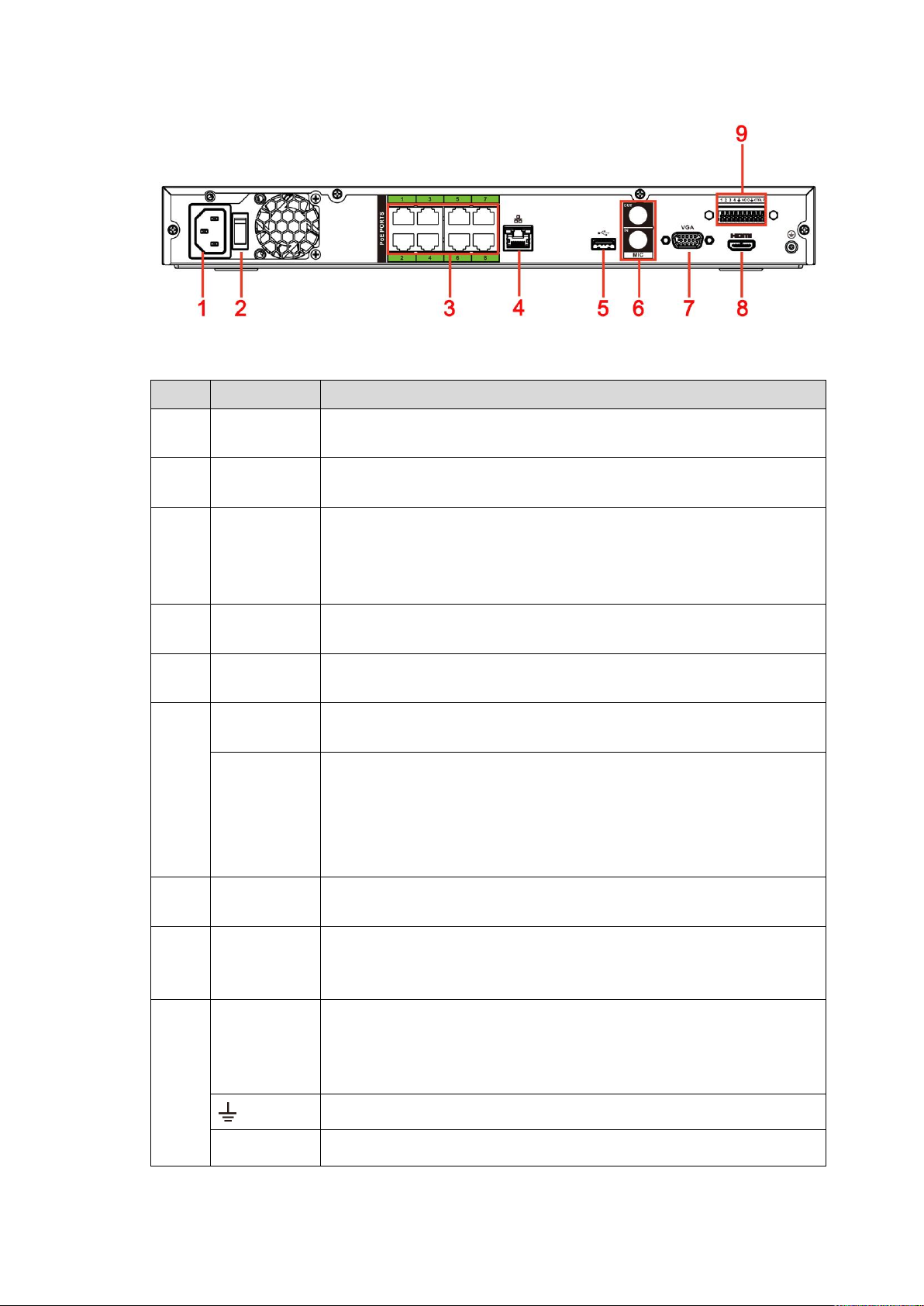
Figure 2-8
No.
Port Name
Function
1
Power input
port
Input power of 100V-240V and 50Hz-60Hz.
2
Power
button
Turns on/off the NVR.
3
PoE port
Built-in switch. It can provide power for IPC.
8 PoE ports: 1-8 are ePoE ports (support 300m @ 100M. 800m @
10M). The device supports 48V, 100W total power output under
55℃, and 48V, 130W total power output under 45℃.
4
Network port
10M/100M/1000Mbps self-adaptive Ethernet port. Connect to the
network cable.
5
USB port
USB3.0 port. Connect to devices such as mouse, USB storage
device and USB burner.
6
MIC IN
Bidirectional talk input port. It is to receive analog audio signal from
devices such as microphone, sound pickup.
MIC OUT
Audio output port. It is to output analog audio signal to devices such
as sound box.
Bidirectional talk output.
Audio output on 1-window video monitor.
Audio output on 1-window video playback.
7
VGA port
VGA video output port. Output analog video signal. It can connect to
the monitor to view analog video.
8
HDMI port
High definition audio and video signal output port. It transmits
uncompressed high definition video and multiple-channel audio data
to displays with HDMI port.
9
Alarm input
port (1-4)
They receive signals from external alarm source. Alarm input
includes two types; NO (normal open) and NC (normal close).
When your alarm input device is using external power, make
sure the device and the NVR have the same GND.
GND. Alarm input ground port.
NO C
One NO activation output group. (On-off button).
Table 2-5
Front Panel and Rear Panel 12
Page 22
No.
Port Name
Function
CTRL
Controllable power supply output. Control the output of the on-off
button alarm relay. It controls the alarm device with the presence or
absence of voltage. It can also be used as power input for some
alarm devices such as alarm detectors.
P
Power output port. It can provide power to some peripheral devices
such as camera and alarm device. Make sure the power supply of
peripheral device shall be below 1A.
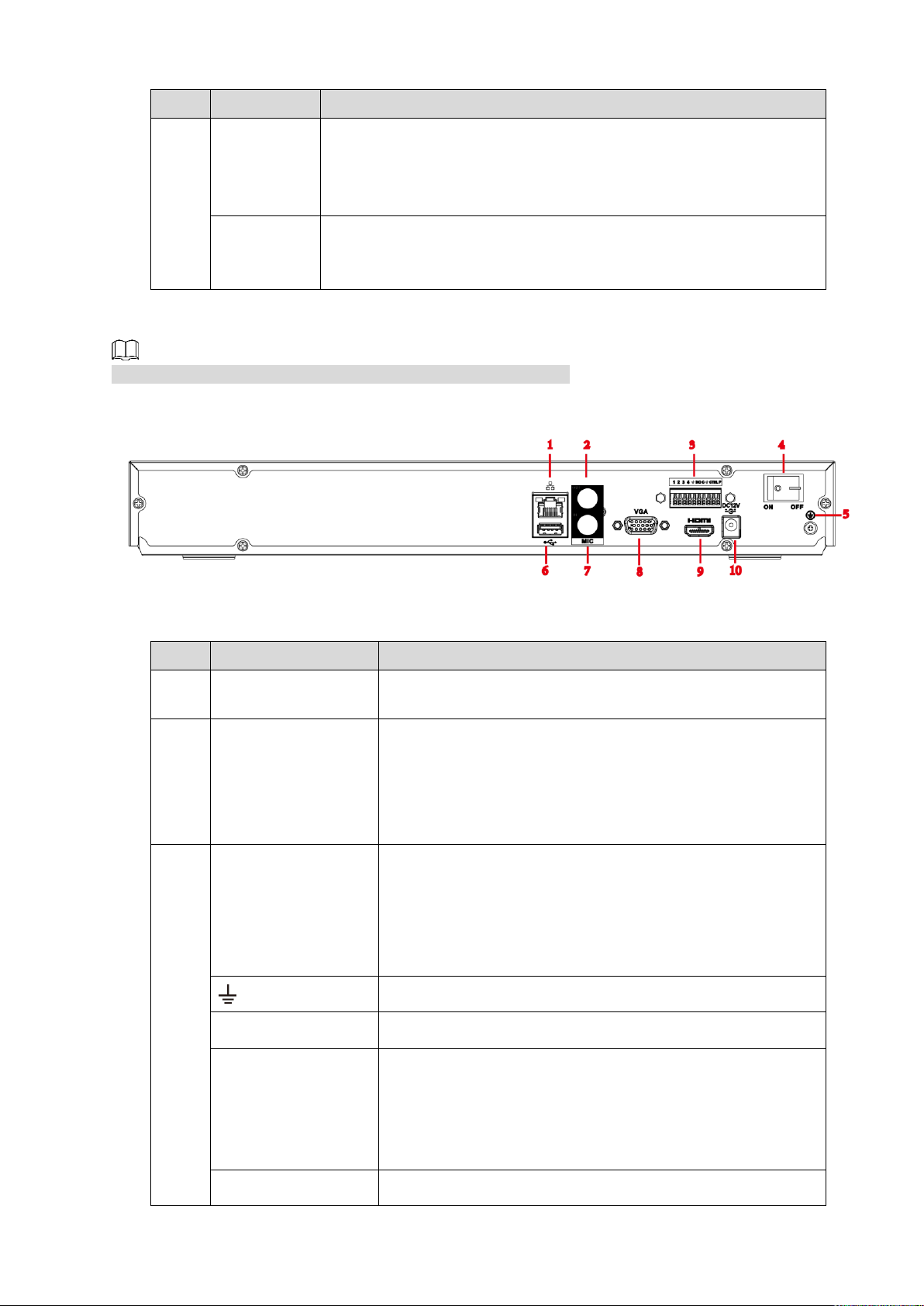
2.2.5 NVR4216-I Series
No.
Port Name
Function
1
Network port
10M/100M/1000Mbps self-adaptive Ethernet port. Connect
to the network cable.
2
MIC OUT
Audio output port. It is to output analog audio signal to
devices such as sound box.
Bidirectional talk output.
Audio output on 1-window video monitor.
Audio output on 1-window video playback.
3
Alarm input port
(1-4)
They receive signals from external alarm source. Alarm
input includes two types; NO (normal open) and NC
(normal close).
When your alarm input device is using external power,
make sure the device and the NVR have the same
GND.
GND. Alarm input ground port.
NO C
One NO activation output group. (On-off button).
CTRL
Controllable power supply output. Control the output of the
on-off button alarm relay. It controls the alarm device with
the presence or absence of voltage. It can also be used as
power input for some alarm devices such as alarm
detectors.
P
Power output port. It can provide power to some peripheral
The figure is for reference only. The actual product shall prevail.
Figure 2-9
Table 2-6
Front Panel and Rear Panel 13
Page 23
No.
Port Name
Function
devices such as camera and alarm device. Make sure the
power supply of peripheral device shall be below 1A.
4
Power button
Turns on/off the NVR.
5 GND.
6
USB port
USB3.0 port. Connect to devices such as mouse, USB
storage device and USB burner.
7
MIC IN
Bidirectional talk input port. It is to receive analog audio
signal from devices such as microphone, sound pickup.
8
VGA port
VGA video output port. Output analog video signal. It can
connect to the monitor to view analog video.
9
HDMI port
High definition audio and video signal output port. It
transmits uncompressed high definition video and
multiple-channel audio data to displays with HDMI port.
10
Power input port
Input power of 100V-240V and 50Hz-60Hz.
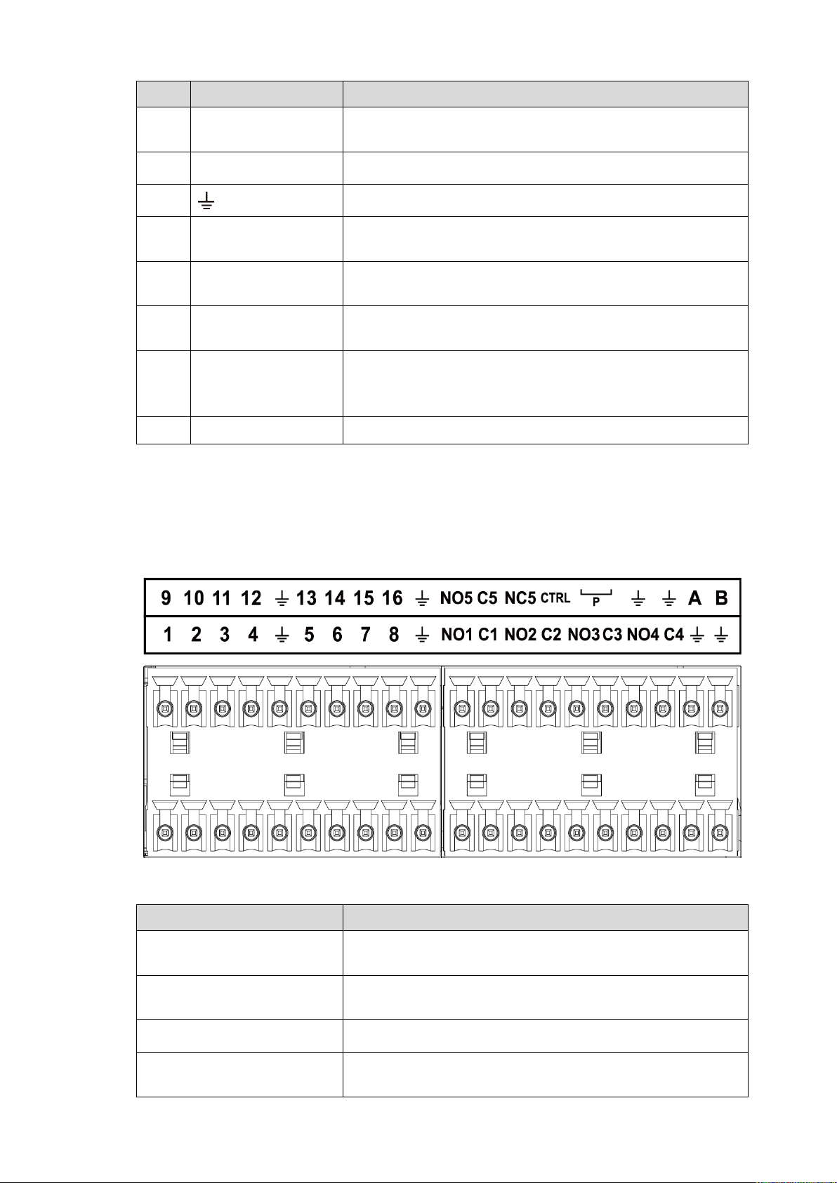
2.3 Alarm Connection
Icon
Function
1–16
ALARM1–ALARM16. The alarm becomes activated in the
low level.
NO1 C1, NO2 C2, NO3 C3,
NO4 C4
Four NO activation output groups. (On-off button).
NO5 C5 NC5
One NO/NC activation output group. (On-off button).
CTRL
Controllable power supply output. Control the output of the
on-off button alarm relay. It controls the alarm device with
2.3.1 Alarm Port
The alarm port is shown as below. See Figure 2-10. The following figure for reference only.
Figure 2-10
Table 2-7
Front Panel and Rear Panel 14
Page 24
Icon
Function
the presence or absence of voltage. It can also be used as
power input for some alarm devices such as alarm
detectors.
Power output port. It can provide power to some peripheral
devices such as camera and alarm device. Make sure the
power supply of peripheral device shall be below 1A.
GND
A/B
485 communication port. They are used to control devices
such as PTZ. Parallel connect 120TΩ between A/B cables if
there are too many PTZ decoders.
Different models support different alarm input ports. Refer to the specifications sheet for detailed
information.
Slight difference may be found on the alarm port layout.
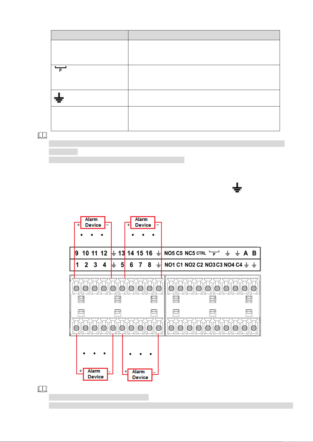
2.3.2 Alarm Input Port
Connect the positive end (+) of the alarm input device to the alarm input port (ALARM IN 1–16) of the
NVR. Connect the negative end (-) of the alarm input device to the ground end ( ) of the NVR.
Figure 2-11
There are two alarm input types: NO/NC.
When connect the ground port of the alarm device to the NVR, you can use any of the GND ports
Front Panel and Rear Panel 15
Page 25

( ).
Model:
JRC-27F
Material of the
touch
Silver
Rating
(resistance
load)
Rated switch capacity
30VDC 2A, 125VAC 1A
Maximum switch power
125VA 160W
Maximum switch voltage
250VAC, 220VDC
Maximum switch currency
1A
Insulation
Between touches with same
polarity
1000VAC 1 minute
Between touches with different
polarity
1000VAC 1minute
Between touch and winding
1000VAC 1minute
Surge voltage
Between touches with same
polarity
1500V (10×160us)
Length of open
time
3ms max
Length of close
time
3ms max
Longevity
Mechanical
50×106 MIN (3Hz)
Electrical
200×103 MIN (0.5Hz)
Temperature
-40°C–+70°C
Connect the NC port of the alarm device to the alarm input port (ALARM) of the NVR.
When there is peripheral power supplying for the alarm device, make sure it is earthed with the NVR.
2.3.3 Alarm Output Port
There is peripheral power supplying for the external alarm device.
In case overload may result in NVR damage, refer to the following relay specifications for detailed
information.
A/B cable of the RS485 is for the A/B cable connection of the speed PTZ.
2.3.4 Alarm Relay Specifications
Table 2-8
2.4 Bidirectional talk
2.4.1 Device-end to PC-end
Device Connection
Connect the speaker or the pickup to the first audio input port in the device rear panel. Then connect the
earphone or the sound box to the audio output port in the PC.
Login the Web and then enable the corresponding channel real-time monitor.
Refer to the following interface to enable bidirectional talk. See Figure 2-12.
Front Panel and Rear Panel 16
Page 26

Figure 2-12
Listening Operation
At the device end, speak via the speaker or the pickup, and then you can get the audio from the earphone
or sound box at the pc-end. See Figure 2-13.
The following figure is for reference only.
Figure 2-13
2.4.2 PC-end to the device-end
Device Connection
Connect the speaker or the pickup to the audio output port in the PC and then connect the earphone or
the sound box to the first audio input port in the device rear panel.
Login the Web and then enable the corresponding channel real-time monitor.
Refer to the above interface (Figure 2-12) to enable bidirectional talk.
Listening Operation
At the PC-end, speak via the speaker or the pickup, and then you can get the audio from the earphone or
sound box at the device-end. See Figure 2-14.
The following figure is for reference only.
Figure 2-14
2.5 Mouse Operation
Refer to the following sheet for mouse operation instruction.
Front Panel and Rear Panel 17
Page 27
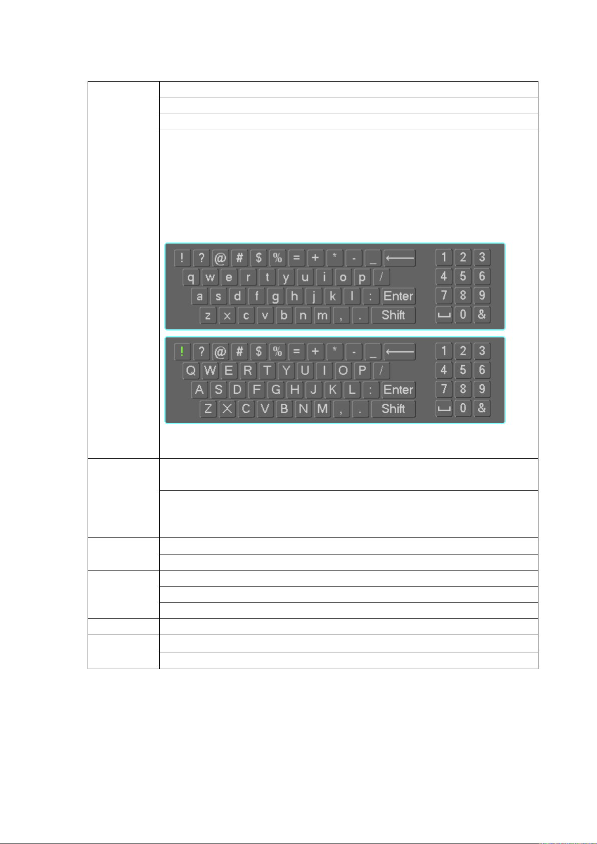
Table 2-9
Left click
mouse
When you have selected one menu item, left click mouse to view menu content.
Modify checkbox or motion detection status.
Click combo box to pop up dropdown list
In input box, you can select input methods. Left click the corresponding button
on the panel you can input numeral/English character (small/capitalized). Here
← stands for backspace button. _ stands for space button.
In English input mode: _stands for input a backspace icon and ← stands for
deleting the previous character.
In numeral input mode: _ stands for clear and ← stands for deleting the
previous numeral.
Double left
click mouse
Implement special control operation such as double-click one item in the file list
to playback the video.
In multiple-window mode, double left click one channel to view in full-window.
Double-left click current video again to go back to previous multiple-window
mode.
Right click
mouse
In real-time monitor mode, pops up shortcut menu.
Exit current menu without saving the modification.
Press middle
button
In numeral input box: Increase or decrease numeral value.
Switch the items in the check box.
Page up or page down
Move mouse
Select current control or move control
Drag mouse
Select motion detection zone
Select privacy mask zone.
2.6 Remote Control
The remote control interface is shown as in Figure 2-15.
The remote control is not our standard accessory and it is not included in the accessory bag.
Front Panel and Rear Panel 18
Page 28
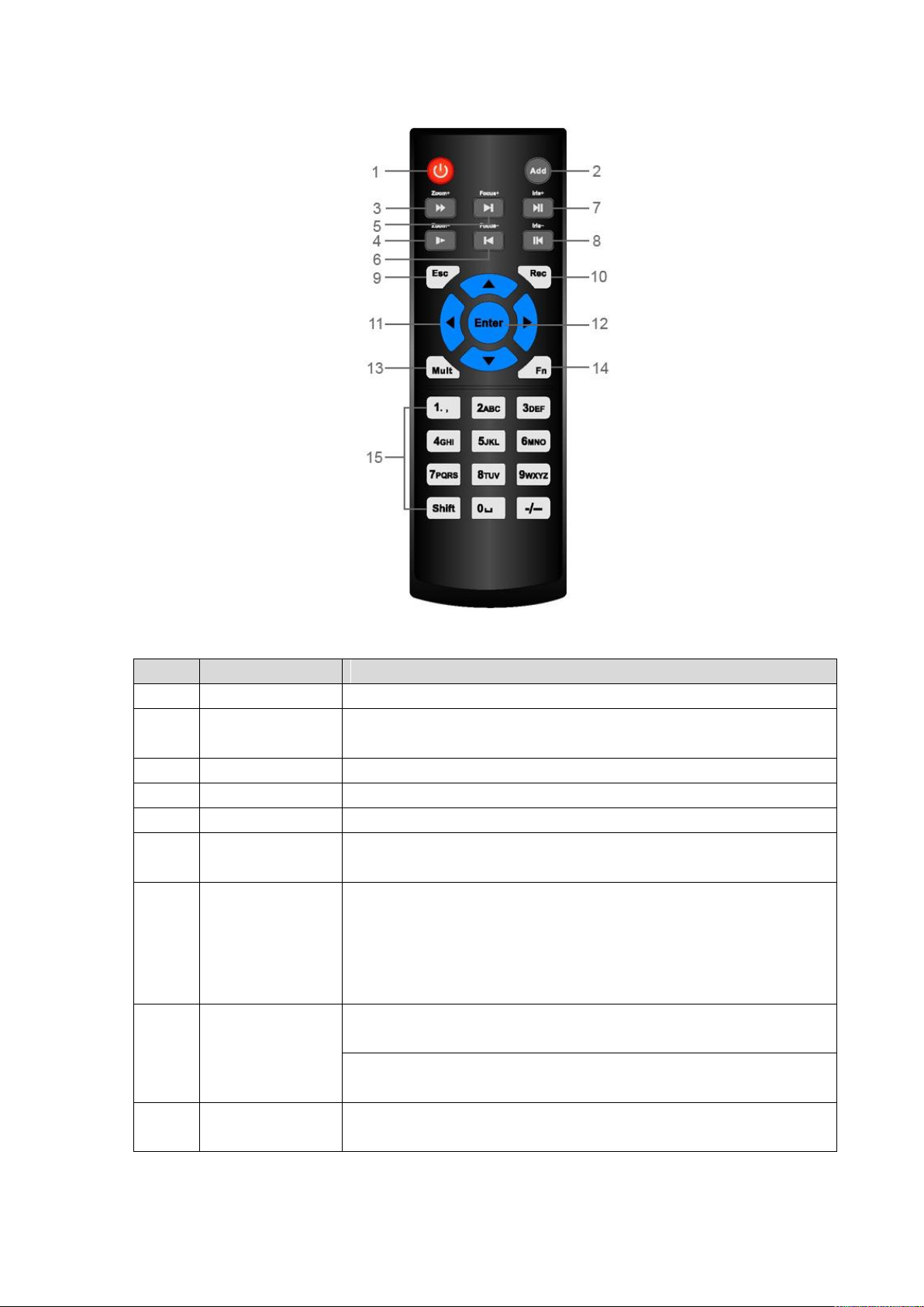
Figure 2-15
No.
Name
Function
1
Power button
Press this button to boot up or shut down the device.
2
Address
Press this button to input device serial number, so that you can
control the Device.
3
Forward
Multi-step forward speed and normal speed playback.
4
Slow motion
Multi-step slow motion speed or normal playback.
5
Next record
In playback state, press this button to play back the next video.
6
Previous record
In playback state, press this button to play back the previous
video.
7
Play/Pause
In normal playback state, press this button to pause playback.
In pause state, press this button to resume to normal
playback.
In live view window interface, press this button to enter video
search menu.
8
Reverse/pause
In the reverse playback state, press this button to pause reverse
playback.
In the reverse playback pause state, press this button to resume to
playback reversing state.
9
Esc.
Go back to previous menu or cancel current operation (close front
interface or control).
Table 2-10
Front Panel and Rear Panel 19
Page 29

No.
Name
Function
10
Record
Start or stop record manually.
In record interface, use the direction buttons to select the
channel that you want to record.
Press this button for at least 1.5 seconds, and the manual
record interface will be displayed.
11
Direction keys
Switch between current activated controls by going left or right.
In playback state, the keys control the playback progress bar.
Aux function (such as operating the PTZ menu).
12
Enter/menu key
Confirms an operation.
Go to the OK button.
Go to the menu.
13
Multiple-window
switch
Switch between multiple-window and one-window.
14
Fn
In single-channel monitoring mode, press this button to
display the PTZ control and color setting functions.
Switch the PTZ control menu in PTZ control interface.
In motion detection interface, press this button with direction
keys to complete setup.
In text mode, press and hold this button to delete the last
character. To use the clearing function: Long press this button
for 1.5 seconds.
In HDD menu, switch HDD recording time and other
information as indicated in the pop-up message.
15
Alphanumeric
keys
Input password, numbers.
Switch channel.
Press Shift to switch the input method.
Front Panel and Rear Panel 20
Page 30
3 Device Installation
Note: All the installation and operations here should conform to your local electric safety rules.
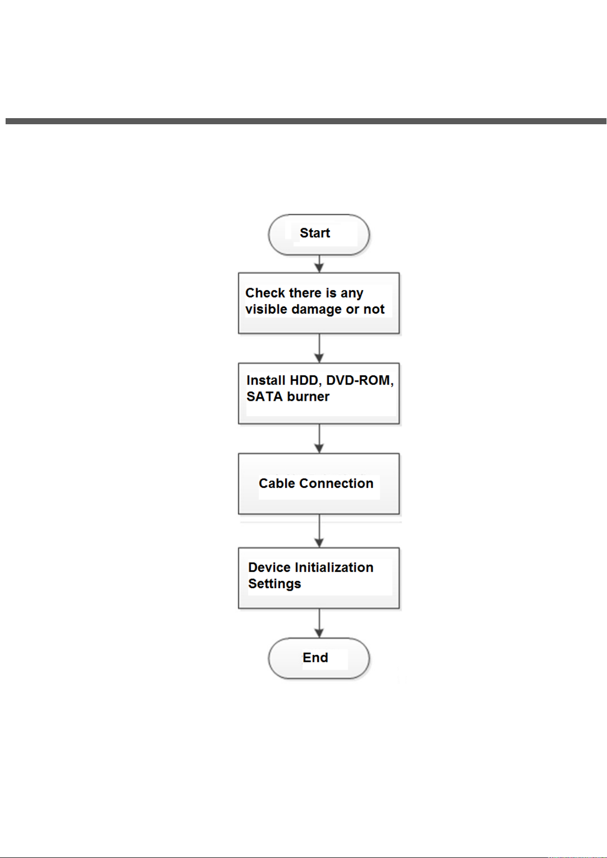
3.1 Device Installation Diagrams
Refer to the following diagrams to install the NVR.
3.2 Check Unpacked NVR
After you received the NVR from the forwarding agent, check whether there is any visible damage. The
protective materials used for the package of the NVR can protect most accidental clashes during
transportation. Then you can open the box to check the accessories.
Check the items in accordance with the list. Finally you can remove the protective film of the NVR.
Device Installation 21
Page 31

3.3 About Front Panel and Rear Panel
The model number in the stick on the bottom of NVR is very important; check according to your purchase
order.
The label in the rear panel is very important too. Usually we need you to represent the serial number
when we provide the service after sales.
3.4 HDD Installation
For the first time installation, make sure whether the HDD has been installed or not. We recommend to
use HDD of enterprise level or surveillance level. It is not recommended to use PC HDD.
Shut off the power before you replace the HDD.
Use the dedicated SATA HDD for monitoring recommended by the HDD manufacturer.
You can refer to the Appendix for HDD space information and recommended HDD brand.
3.4.1 NVR58-I/54-16P-I/4832-I/4416-16P-I/4432-I Series
Different models have different HDD numbers. The actual product shall prevail.
Remove the fixing screws on the rear panel of the device.
Figure 3-1
Remove the case cover along the direction shown in the following arrow.
Figure 3-2
Remove the screws on the sides of HDD bracket to take out the bracket.
1.5U device has one HDD bracket. For the way to remove the bracket, see Figure 3-3
2U device has two HDD brackets. For the way to remove the brackets, see Figure 3-4.
Device Installation 22
Page 32

Figure 3-3
Figure 3-4
Match the four screw holes on the HDD with the four holes on the bracket and then fasten the screws.
The HDD is fixed to the bracket.
Figure 3-5
Refer to Step 4 to install other HDDs.
Figure 3-6
Lock the two HDD brackets.
This step is required for 2U devices only.
Device Installation 23
Page 33

Figure 3-7
Place the bracket to the device and then fasten the screws on the sides of the bracket.
Figure 3-8
Connect the HDD data cable and power cable to the device.
The following figure is for reference only. The actual product shall prevail.
Figure 3-9
Put back the cover and fasten the screws on the rear panel to complete the installation.
Device Installation 24
Page 34

Figure 3-10
3.4.2 NVR52-16P-I/52-8P-I/4216-16P-I/4208-8P-I/4216-I Series
Different models have different HDD numbers. The actual product shall prevail.
Remove the four fixing screws on the rear panel.
Figure 3-11
Remove the case cover along the direction shown in the following arrow.
Figure 3-12
Match the four holes on the baseboard to place the HDD.
Device Installation 25
Page 35

Figure 3-13
Turn the device upside down, match the screws with the holes on the HDD and then fasten them. The
HDD is fixed to the baseboard.
Figure 3-14
Connect the HDD data cable and power cable to the device.
Figure 3-15
Put back the cover and fasten the four screws on the rear panel to complete the installation.
Device Installation 26
Page 36

3.5 CD-ROM Installation
① Open top cover and then remove the
HDD bracket
② Take off the bottom of the HDD bracket and CD-ROM
bracket.
③ Fix the CD-ROM bracket at the HDD
bracket.
④ Install a pair of the CD-ROM bracket. Make sure the
reverse side is secure too.
Follow the steps listed below.
Figure 3-16
Device Installation 27
Page 37

⑤ Install SATA burner. Line up the SATA
burner to the hole positions.
⑥ User screwdriver to fix the screws.
⑦ Put the bracket back. Adjust the
CD-ROM to the proper position so that
the button of the front panel is directly
facing the pop-up button of the CD-ROM.
⑧ Connect the SATA cable and power wire.
⑨ Secure the HDD bracket and put the top
cover back.
3.6 Connection Sample
3.6.1 NVR58-I/4832-I Series
The following figure is for reference only. The actual product shall prevail.
Device Installation 28
Page 38

Figure 3-17
3.6.2 NVR54-16P-I/4416-16P-I/4432-I Series
The following figure is for reference only. The actual product shall prevail.
Figure 3-18
3.6.3 NVR52-16P-I/52-8P-I/4216-16P-I/4208-8P-I/4216-I Series
The following figure is for reference only. The actual product shall prevail.
Device Installation 29
Page 39

Figure 3-19
Device Installation 30
Page 40

Slight difference may be found on the user interface. The following figures for reference only.
4.1 Getting Started
This chapter introduces device initial settings such as boot up, device initialization, reset
password, and quick settings.
4.1.1 Boot up
For device security, connect the NVR to the power adapter first and then connect the device
to the power socket.
The rated input voltage matches the device power button. Make sure the power wire
connection is OK. Then click the power button.
Always use the stable current, if necessary UPS is a best alternative measure.
Step 1 Connect the device to the monitor and then connect a mouse.
Step 2 Connect power cable.
Step 3 Click the power button at the front or rear panel and then boot up the device. After
device booted up, the system is in multiple-channel display mode by default.
4.1.2 Device Initialization
4 Local Basic Operations
If it is your first time to use the device, set a login password of admin (system default user). You
can select to use unlock pattern to login or not at your own choosing.
For your device safety, keep your login password of admin well after the initialization steps, and
change the password regularly.
Step 1 Boot up NVR.
The Device Initialization interface is displayed. See Figure 4-1.
Local Basic Operations 31
Page 41

Figure 4-1
Step 2 Set system time zone according to the actual environment. Refer to Table 4-4 in
"4.1.4.1.2 Date and Time" for detailed information.
Click to shut down the device. It is suitable for the system integrator or the user to
shut down directly after setting the time zone.
Step 3 Click Next.
The Device Initialization interface is displayed. See Figure 4-2.
Local Basic Operations 32
Page 42

Figure 4-2
Parameter
Description
User
By default, the user is admin.
Password
In the Password box, enter the password for admin.
The new password can be set from 8 characters through 32
characters and contains at least two types from number, letter and
special characters (excluding"'", """, ";", ":" and "&").
Confirm Password
Prompt Question
In the Prompt Question box, enter the information that can remind
you of the password.
On the login interface, click , the prompt will display to help you
reset the password.
Step 4 Set login password of admin. See Table 4-1.
Table 4-1
For your device own safety, create a strong password of your own choosing. We also
recommend you change your password periodically especially in the high security system.
Step 5 Click Next.
The Unlock Pattern interface is displayed. See Figure 4-3.
Local Basic Operations 33
Page 43

Figure 4-3
Step 6 Set unlock pattern.
After set unlock pattern, the Password Protection interrface is displayed. See Figure
4-4.
The pattern that you want to set must cross at least four grids.
If you do not want to configure the unlock pattern, click Skip.
Once you have configured the unlock pattern, the system will require the unlock
pattern as the default login method. If you skip this setting, enter the password for
login.
Local Basic Operations 34
Page 44

Figure 4-4
Password
Protection Mode
Description
Email Address
Enter the reserved email address.
In the Email Address box, enter an email address for password
reset. If you forget the password, enter the security code that you will
get from this reserved email address to reset the password of admin.
Refer to " 4.15.1.2 Modify Password" for detailed information.
Security
Questions
Configure the security questions and answers.
If you forget the password, enter the answers to the questions can
allow you reset the password. Refer to " 4.15.3 Reset Password "
for detailed information.
Step 7 Set security questions. See Table 4-2.
After configuration, if you forgot the password for admin user, you can reset the
password through the reserved email address or security questions. For details
about resetting the password, see “4.1.3 Reset Password".
If you do not want to configure the settings, disable the email address and security
questions functions on the interface.
Table 4-2
Step 8 Click Save to complete the device initialization setup.
Step 9 Device goes to startup wizard interface. Refer to “4.1.4 Quick Settings" for detailed
information.
4.1.3 Reset Password
You can reset the password by the following methods when you forgot the password for admin
account.
Local Basic Operations 35
Page 45

If the password reset function is enabled, you can use mobile phone to scan the QR code to
reset the password. For details, see "4.1.3.2 Resetting Password on Local Interface."
If the password reset function is disabled, there are two situations:
If you configured security questions, you can reset the password by the security
questions.
If you did not configure the security questions, you can only use the reset button on the
mainboard to restore the Device to factory default.
Reset button is for some series product only.
4.1.3.1 Enabling Password Reset Function
After enabling password reset function, you can scan QR code on the local menu to reset
password.
Step 1 Select Main Menu > Account > Reset Password.
The Reset Password interface is displayed. See Figure 4-5.
Figure 4-5
Step 2 Check the box to enable reset function.
This function is enabled by default.
Step 3 Click Apply to set settings.
If the password reset function is disabled, you can follow the ways listed below to reset
password.
Local Basic Operations 36
Page 46

Device supports Reset button on the main board: You can answer the security
question on the local menu or click the Reset button on the main board to reset
password. Refer to “4.1.3.3 Reset Button “for detailed information.
Device does not support Reset button on the main board: You can only answer the
security question on the local menu to reset password. (Make sure you have set
security questions).
4.1.3.2 Resetting Password on Local Interface
Step 1 Enter the SYSTEM LOGIN interface.
If you have configured unlock pattern, the unlock pattern login interface is displayed.
See Figure 4-6. Click Forgot Pattern, the password login interface is displayed.
See Figure 4-7.
If you did not configure unlock pattern, the System Login interface is displayed.
See Figure 4-7.
To login from other user account, on the unlock pattern login interface, click Switch
User, or on the password login interface, in the Switch User list, select other user
to login.
Figure 4-6
Local Basic Operations 37
Page 47

Step 2 Click .
If you have set the reserved email address, the Prompt interface is displayed. See
Figure 4-8.
If you did not set the reserved email address, the email entering interface is
displayed. See Figure 4-9.
Enter the email address, and then click Next, the Prompt message interface is
displayed. See Figure 4-8.
Figure 4-7
Figure 4-8
Local Basic Operations 38
Page 48

Figure 4-9
Step 3 Click Next.
The Reset Password interface is displayed. See Figure 4-10.
After clicking Next, the system will collect your information for password reset, purpose
and the information includes but not limited to email address, MAC address, and device
serial number. Read the prompt carefully before clicking Next.
Figure 4-10
Local Basic Operations 39
Page 49

Step 4 Reset the password.
QR code
Follow the onscreen instructions to get the security code in your reserved email
address. In the Security code box, enter the security code.
You can get the security code twice by scanning the same QR code. If you
need to get the security code once again, refresh the interface.
Use the security code received in your email box to reset the password within
24 hours; otherwise the security code becomes invalid.
Security questions
On the Reset password interface as shown in Figure 4-11, in the Reset Type list,
select Security Questions, the Security Questions interface is displayed.
If you did not configure the security questions before, in the Reset Type list, there is
no Security Questions.
Figure 4-11
Step 5 Click Next.
The Reset Password interface is displayed. See Figure 4-12.
Local Basic Operations 40
Page 50

Figure 4-12
Step 6 In the New Password box, enter the new password and enter it again in the Confirm
Password box.
Step 7 Click Save. The password resetting is complete.
A pop-up message is displayed asking if you want to sync the password with the remote
devices. See Figure 4-13.
Figure 4-13
4.1.3.3 Reset Button
Local Basic Operations 41
Page 51

You can always use the reset button on the mainboard to reset the Device to the factory default
settings.
Reset button is for some series products only.
Step 1 Disconnect the Device from power source, and then remove the cover panel. For details
about removing the cover panel, see "3.4 HDD Installation".
Step 2 Find the reset button on the mainboard, and then connect the Device to the power
source again.
Step 3 Press and hold the reset button for 5 seconds to 10 seconds. See Figure 4-14 for the
location of the reset button.
Figure 4-14
Step 4 Reboot the Device.
After the Device is rebooted, the settings have been restored to the factory default. You
can start resetting the password.
4.1.4 Quick Settings
After you successfully initialized the device, it goes to startup wizard. Here you can quickly
configure your device. Click Next, device goes to General interface.
The startup wizard interface only displays after you first login the device and have set the admin
password. See Figure 4-15.
Local Basic Operations 42
Page 52

Figure 4-15
If you select the Auto-check for updates check box, the system will notify you
automatically when updates are available.
After the auto-check function is enabled, to notify you to update timely, the system will
collect the information such as IP address, device name, firmware version, and device
serial number. The collected information is only used to verify the legality of the Device and
push upgrade notices.
If you cancel the Auto-check for updates check box, the system will not perform automatic
checks.
4.1.4.1 General
You can set NVR basic information such as system date, holiday and etc. You can also configure
general settings by selecting Main Menu > SYSTEM > General.
4.1.4.1.1 General
You can set device basic information such as device name, serial number.
Step 1 Click Next.
The General interface is displayed. See Figure 4-16.
Local Basic Operations 43
Page 53

Figure 4-16
Parameter
Description
Device Name
In the Device Name box, enter the Device name.
Device No.
In the Device No. box, enter a number for the Device.
Language
In the Language list, select a language for the Device system.
Video Standard
In the Video Standard list, select PAL or NTSC according to your actual
situation.
Sync to Remote
Device
Enable this function; the NVR can synchronize information with the
remote device such as Language, video standard, time zone.
Instant Play (Min.)
In the Instant Play box, enter the time length for playing back the
recorded video. The value ranges from 5 to 60.
On the live view control bar, click the instant playback button to play back
the recorded video within the configured time.
Auto Logout (Min.)
In the Auto Logout box, enter the standby time for the Device. The
Device automatically logs out when it is not working for the configured
time period. You need to login the Device again.
The value ranges from 0 to 60. 0 indicates there is not standby time for
the Device.
Click Monitor Channel(s) when logout. You can select the channels
that you want to continue monitoring when you logged out.
IPC Time Sync
Syncs the Device time with IP camera.
Step 2 Set parameters. See Table 4-3.
Table 4-3
Local Basic Operations 44
Page 54

Parameter
Description
IPC Time Sync
Period (hour)
In the IPC Time Sync Period box, enter the interval for time sync.
Auto logout
You can set auto logout interval once login user remains inactive for a
specified time. Value ranges from 0 to 60 minutes.
Navigation Bar
Enable the navigation bar. When you click on the live view screen, the
navigation bar is displayed.
Mouse Sensitivity
Adjust the speed of double-click by moving the slider.
The bigger the value is, the faster the speed is.
Step 3 Click Next button to save settings.
4.1.4.1.2 Date and Time
You can set device time. You can enable NTP (Network Time Protocol) function so that the
device can sync time with the NTP server.
You can also configure date and time settings by selecting Main Menu > SYSTEM >
GENERAL > Date&Time.
Step 1 Click Date & Tim tab. See Figure 4-17.
Figure 4-17
Step 2 Configure the settings for date and time parameters. See Table 4-4.
Local Basic Operations 45
Page 55

Table 4-4
Parameter
Description
System Time
In the System Time box, enter time for the system.
Click the time zone list, you can select a time zone for the system, and
the time in adjust automatically.
Do not change the system time randomly; otherwise the recorded video
cannot be searched. It is recommended to avoid the recording period or
stop recording first before you change the system time.
System Zone
In the System Zone list, select a time zone for the system.
Date Format
In the Date Format list, select a date format for the system.
Date Separator
In the Date Separator list, select a separator style for the date.
Time Format
In the Time Format list, select 12-HOUR or 24-HOUR for the time
display style.
DST
Enable the Daylight Saving Time function. Click Week or click Date.
Start Time
Configure the start time and end time for the DST.
End Time
NTP
Enable the NTP function to sync the Device time with the NTP server.
Server
In the Server box, enter the IP address or domain name of the
corresponding NTP server.
Click Manual Update, the Device starts syncing with the server
immediately.
Port
The system supports TCP protocol only and the default setting is 123.
Interval (Min.)
In the Interval box, enter the amount of time that you want the Device to
sync time with the NTP server. The value ranges from 0 to 65535.
Step 3 Click Next button to save settings.
4.1.4.1.3 Holiday
Here you can add, edit, delete holiday. After you successfully set holiday information, you can
view holiday item on the record and snapshot period.
You can also configure holiday settings by selecting Main Menu > SYSTEM > GENERAL >
Holiday.
Step 1 Click Next.
The Holiday interface is displayed. See Figure 4-18.
Local Basic Operations 46
Page 56

Figure 4-18
Step 2 Click Add Holidays button, the Add Holidays interface is displayed. See Figure 4-19.
Figure 4-19
Step 3 Set holiday name, repeat mode and holiday mode.
Click Add more to add new holiday information.
Step 4 Click Add button, you can add current holiday to the list.
Click the dropdown list of the state; you can enable/disable holiday date.
Click to change the holiday information. Click to delete current date.
Local Basic Operations 47
Page 57

Step 5 Click Next button to save settings.
4.1.4.2 Basic Network Settings
You can set device IP address, DNS (Domain Name System) information. You can also
configure basic network settings by selecting Main Menu > NETWORK > TCP/IP.
Preparation
Make sure the device has properly connected to the network.
Step 1 Click Next.
The TCP/IP interface is displayed. See Figure 4-20.
Different series products have different Ethernet adapter amount and type. Refer to the
actual product.
Figure 4-20
Step 2 Click .
The Edit interface is displayed. See Figure 4-21.
Local Basic Operations 48
Page 58

Figure 4-21
Parameter
Description
Net Mode
Multi-address: Two Ethernet ports work separately through either
of which you can request the Device to provide the services such
as HTTP and RTSP. You need to configure a default Ethernet port
(usually the Ethernet port 1 by default) to request the services from
the device end such as DHCP, Email and FTP. If one of the two
Ethernet ports is disconnected as detected by networking testing,
the system network status is regarded as offline.
Fault Tolerance: Two Ethernet ports share one IP address.
Normally only one Ethernet port is working and when this port fails,
the other port will start working automatically to ensure the network
connection.
When testing the network status, the network is regarded as offline
only when both of the two Ethernet ports are disconnected. The
two Ethernet ports are used under the same LAN.
Load Balance: Two network cards share one IP address and they
are working at the same time to share the network load averagely.
If one of them fails, the other can continue working normally.
When testing the network status, the network is regarded as offline
only when both of the two Ethernet ports are disconnected. The
two Ethernet ports are used under the same LAN.
The Device with single Ethernet port does not support this function.
Default Ethernet Port
In the Ethernet Card list, select an Ethernet port as a default port.
This setting is available only when the Multi-address is selected in the
Net Mode list.
Step 3 Set parameters. See Table 4-5.
Table 4-5
Local Basic Operations 49
Page 59

Parameter
Description
IP Version
In the IP Version list, you can select IPv4 or IPv6. Both versions are
supported for access.
MAC Address
Displays the MAC address of the Device.
DHCP
Enable the DHCP function. The IP address, subnet mask and default
gateway are not available for configuration once DHCP is enabled.
If DHCP is effective, the obtained information will display in the IP
Address box, Subnet Mask box and Default Gateway box. If not,
all values show 0.0.0.0.
If you want manually configure the IP information, disable the
DHCP function first.
If PPPoE connection is successful, the IP address, subnet mask,
default gateway, and DHCP are not available for configuration.
IP Address
Enter the IP address and configure the corresponding subnet mask and
default gateway.
IP address and default gateway must be in the same network segment.
Subnet Mask
Default Gateway
DNS DHCP
Enable the DHCP function to get the DNS address from router.
Preferred DNS
In the Preferred DNS box, enter the IP address of DNS.
Alternate DNS
In the Alternate DNS box, enter the IP address of alternate DNS.
MTU
In the MTU box, enter a value for network card. The value ranges from
1280 byte through 1500 byte. The default is 1500.
Test
Click Test to test if the entered IP address and gateway are
interworking.
Step 4 Click OK to NIC settings.
Parameter
Description
IP Version
There are two options: IPv4 and IPv6. Right now, system supports
these two IP address format and you can access via them.
Preferred DNS server
DNS server IP address.
Alternate DNS server
DNS server alternate address.
MAC Address
Displays the MAC address of the Device.
DHCP
Enable the DHCP function. The IP address, subnet mask and default
gateway are not available for configuration once DHCP is enabled.
If DHCP is effective, the obtained information will display in the IP
Address box, Subnet Mask box and Default Gateway box. If not,
all values show 0.0.0.0.
If you want manually configure the IP information, disable the
DHCP function first.
Device goes back to TCP/IP interface.
Step 5 Set network parameters. See Table 4-6.
Table 4-6
Local Basic Operations 50
Page 60

Parameter
Description
If PPPoE connection is successful, the IP address, subnet mask,
default gateway, and DHCP are not available for configuration.
LAN download
System can process the downloaded data first if you enable this
function. The download speed is 1.5X or 2.0X of the normal speed.
For IPv6 version, the IP address, default gateway, preferred DNS;
alternate DNS is 128-digit. Fill in all items here.
This function is for some series product only.
Step 6 Click Next to complete the settings.
4.1.4.3 P2P
Scan the QR code, download the App to the cell phone, you can use the smart phone to add the
device.
Scan the QR code on the actual interface to download the cell phone app. Register an
account and then use.
Go to the www.easy4ip.com to register an account and use the SN to add a device. Refer to
the P2P operation manual for detailed information.
Before use the P2P function, make sure the NVR has connected to the WAN.
Step 1 Click Next button.
The P2P interface is displayed. See Figure 4-22.
Select Main Menu > Network > P2P, you can go to P2P interface too.
Local Basic Operations 51
Page 61

Figure 4-22
Step 2 Check the box to enable P2P function.
After the P2P function is enabled and connected to the Internet, the system will collects
your information for remote access, and the information includes but not limited to email
address, MAC address, and device serial number.
Step 3 Click Next button to complete setup.
The status is online if the P2P registration is successful.
Client Operation
Step 1 Use your cell phone to scan the QR code under Cell Phone Client to download the
application.
Step 2 On your cell phone, open the application, and then tap .
Step 3 The menu is displayed. You can start adding the device.
1) Tap Device Manager.
The Device Manager interface is displayed. See Figure 4-23.
Local Basic Operations 52
Page 62

Figure 4-23
2) Tap on the top right corner.
The interface requiring device initialization is displayed. A pop-up message
reminding you to make sure the Device is initialized is displayed.
3) Tap OK.
If the Device has not been initialized, Tap Device Initialization to perform
initializing by following the onscreen instructions.
If the Device has been initialized, you can start adding it directly.
4) Tap Add Device.
The Add Device interface is displayed. See Figure 4-24.
You can add wireless device or wired device. The Manual takes adding wired
device as an example.
Figure 4-24
Local Basic Operations 53
Page 63

5) Tap P2P.
The P2P interface is displayed. See Figure 4-25.
Figure 4-25
6) Enter a name for the NVR, the username and password, scan the QR code under
Device SN.
7) Tap Start Live Preview.
The Device is added and displayed on the live view interface of the cell phone. See
Figure 4-26.
4.1.4.4 Registration
If you do not select Smart add function during the initialization process, go to the remote Device
interface to register a remote device.
Figure 4-26
Local Basic Operations 54
Page 64

After adding remote device, the device can receive, store, and manage the video streams of the
remote device. You can view, browse, play back and manage several remote devices at the
same time.
Step 1 On the P2P interface, click Next button.
The REGISTRATION interface is displayed. See Figure 4-27.
There are two ways to go to Registration interface.
Select Main Menu > CAMERA > REGISTRATION > Camera Registration, you
can go to the Camera Registration interface.
On the preview interface, right click mouse and then select Camera Registration.
Figure 4-27
Step 2 Register remote device.
Search and then add
1) Click Device Search.
System displays searched devices at the upper pane.
2) Double-click a remote device, or select a remote device and then click Add to
register it to the Added Device list. See Figure 4-28. Refer to
3) Table 4-7 to set parameters.
The search results do not display the remote camera that has registered to the
system
Local Basic Operations 55
Page 65

Figure 4-28
Parameter
Description
Uninitialized
Enable the Uninitialized function, the uninitialized devices out of the
searched devices are displayed in the searched device list.
Initialize
Select the uninitialized device from the uninitialized device list, and
the click Initialize to start initializing device.
Show Filter
In the Show Filter list, select the remote device type that you want to
display in the searched device list.
None: Display all types of devices.
IPC: Display the front-end devices.
DVR: Display all storage devices such as NVR, DVR and HCVR.
OTHER: Display the devices that do not belong to IPC or DVR
type.
Searched Device
List
Displays the searched devices. You can view the device information
such as status, IP address.
Device Search
Click Device Search, the searched devices display in the searched
device list.
To adjust the display sequence, in the title line, you can click the IP
address, Manufacturer, Type, MAC Address, Port, or Device Name
text. For example, click the IP address text, the sequence icon
is displayed.
"*" is displayed next to the added device.
Add
In the Searched Device List area, select the device that you want to
add.
Table 4-7
Local Basic Operations 56
Page 66

Parameter
Description
Manual Add
Add the device by manually configuring settings such as IP address,
channel selection.
Added Device
List
Displays the added devices. You can edit and delete the device, and
view the device information.
Delete
Select the check box of the added device, and then click Delete to
delete the added device.
Import
Select the searched devices and then click Import to import the
devices in batches.
Export
Select the added devices and then click Export. The exported
devices information is saved into the USB storage device.
Manual Add
Parameter
Description
Channel
In the Channel list, select the channel that you want use on the
Device to connect the remote device.
Manufacturer
In the Manufacturer list, select the manufacturer of the remote
device.
IP Address
In the IP Address box, enter the IP address of remote device.
1) Click Manual Add.
The Manual Add interface is displayed. See Figure 4-29.
Figure 4-29
2) Configure parameters. See Table 4-8.
Table 4-8
Local Basic Operations 57
Page 67

Parameter
Description
The default is 192.168.0.0 which the system cannot connect to.
RTSP Port
The default value setting is 554. You can enter the value according to
your actual situation.
HTTP Port
The default value setting is 80. You can enter the value according to
your actual situation.
If you enter other value, for example, 70, and then you should enter
70 after the IP address when logging in the Device by browser.
User Name
Enter the user name of the remote device.
Password
Enter the password of the user for the remote device.
Remote Channel
Enter the remote channel number of the remote device that you want
to add.
Decoder Buffer
In the Decoder Buffer list, select Default, Realtime, or Fluent.
Protocol Type
If the remote device is added through private protocol, the default
type is TCP.
If the remote device is added through Onvif protocol, the system
supports Auto, TCP, UDP, or MULTICAST.
If the remote device is added through other manufacturers, the
system supports TCP and UDP.
Encrypt
If the remote device is added through Onvif protocol, selecting the
Encrypt check box will provide encryption protection to the data being
transmitted.
To use this function, the HTTPS function should be enabled for the
remote IP camera.
3) Click OK.
The remote device information is displayed on the Added Device list.
Step 4 Click Next to complete the remote device registration.
Click to change the remote device information. Click to delete remote device.
Once the multiple-sensor device has registered to the device system displays the channel status on
the Link info. See Figure 4-30. It shows one remote device has occupied two channels: D1, D3.
Local Basic Operations 58
Page 68

Figure 4-30
4.1.4.5 RAID Manager
RAID (redundant array of independent disks) is a data storage virtualization technology that
combines multiple physical HDD components into a single logical unit for the purposes of data
redundancy, performance improvement, or both.
RAID function is for some series product only. Slight difference may be found on the user interface.
Step 1 Select Main Menu > STORAGE > RAID > RAID.
The RAID interface is displayed. See Figure 4-31.
Local Basic Operations 59
Page 69

Figure 4-31
Step 2 You can click Create RAID or Create Manually, and all the disks involved will be
formatted.
Click Create RAID, the system will create RAID automatically.
If there is no existing RAID and no hot spare disk, the system will create RAID5
and a hot spare disk automatically.
If there is no existing RAID, but existing hot spare disk, the system will only create
RAID5 and use the existing hot spare disk automatically.
If there is existing RAID and existing hot spare disk, the system will delete the
original RAID and create RAID5 with all the disks and use the existing hot spare
disk automatically.
Click Create Manually.
1) Select RAID type and disks as system instructed.
2) Click Create Manually, and then the format disk notice is displayed.
3) Click OK.
Step 3 After creating RAID, the disks need to sync with each other to finish the process. For
RAID5 and RAID6, you can select different working mode.
Self-Adaptive: Automatically adjust the RAID sync speed according to the business
status.
When there is no business running, sync is performed at a high speed.
When there is business running, sync is performed at a low speed.
Sync First: Resource priority is assigned to RAID sync.
Business First: Resource priority is assigned to business operations.
Balance: Resource is evenly distributed to RAID sync and business operations.
4.1.4.6 Schedule
After set record schedule and snapshot schedule, the device can automatically record video and
snapshot image at the specified time. Select Main menu > STORAGE > SCHEDULE, you can go to
Local Basic Operations 60
Page 70

the SCHEDULE interface.
Parameter
Description
Channel
In the Channel list, select a channel to record the video.
Pre-record
In the Pre-record list, enter the amount of time that you want to start
the recording in advance.
Redundancy
If there are several HDDs installed to the Device, you can set one of
the HDDs as the redundant HDD to save the recorded files into
different HDDs. In case one of the HDDs is damaged, you can find the
backup in the other HDD.
Select Main Menu > STORAGE > HDD MANAGER, and then
set a HDD as redundant HDD.
Select Main Menu > STORAGE > SCHEDUE > Record, and
4.1.4.6.1 Recording Schedule
After set schedule record, device can record video file according to the period you set here. For
example, the alarm record period is from 6:00–18:00 Monday, device can record alarm video
files during the 6:00–18:00.
All channels are record continuously by default. You can set customized record period and
record type.
Step 1 Click Next button.
The Rec interface is displayed. See Figure 4-32.
Figure 4-32
Step 2 Select a channel from the dropdown list, you can set different record plans for different
channels. Select All if you want to set for all channels. See Table 4-9.
Table 4-9
Local Basic Operations 61
Page 71

Parameter
Description
then select the Redundancy check box.
If the selected channel is not recording, the redundancy function
takes effect next time you record no matter you select the check
box or not.
If the selected channel is recording, the current recorded files will
be packed, and then start recording according to the new
schedule.
This function is for some series products only.
The redundant HDD only back up the recorded videos but not
snapshots.
ANR
You can set ANR (auto network resume) function.
The IPC continues record once the NVR and IPC connection
fails. After the network becomes normal, the NVR can download
record file during the offline period from the IPC. It is to guarantee
there is no record loss on current connected IPC channel.
Set the max. record upload period. Once the offline period is
longer than the period you set here, IPC can only upload the
record file during the specified period.
This function is for IPC that installed SD card and the record function
is enabled.
Period
Define a period during which the configured recording setting is
active. See Figure 4-33.
The system only activates the alarm in the defined period.
Copy
Click Copy to copy the settings to other channels.
Figure 4-33
Local Basic Operations 62
Page 72

Step 3 Set record type. See Figure 4-34.
When the record type is MD (motion detect), alarm, MD&Alarm, IVS and POS,
When the record type is MD (motion detect), alarm, MD&Alarm, IVS and POS, refer
Figure 4-34
enable the channel record function when corresponding alarm occurs. For example,
when the alarm type is MD, select Main Menu > ALARM > VIDEO DETECTION >
Motion Detect, select the record channel and enable record function. See Figure
4-35.
to “4.8.5 Video detect ", "4.8.3 Alarm ", " 4.7.2.4 IVS " and " Step 3 POS " for
detailed information.
Figure 4-35
Step 4 Set record period. It includes edit mode and draw mode. See Figure 4-36.
If you have added a holiday, you can set the record period for the holiday.
Local Basic Operations 63
Page 73

Figure 4-36
Define the period by drawing.
1) Select a corresponding date to set.
Define for the whole week: Click next to All, all the icon switches to ,
you can define the period for all the days simultaneously.
Define for several days of a week: Click before each day one by one, the
icon switches to . You can define the period for the selected days
simultaneously.
2) On the timeline, left click mouse and then drag to define a period.
There are six periods in one day, the Device starts recoding the selected event type
in the defined period. In Figure 4-37, the different color bars stand for different
record types.
Green stands for general record.
Yellow stands for MD (motion detection) record.
Red stands for alarm record.
Blue stands form intelligent record.
Orange stands for MD&Alarm record.
Purple stands for POS record.
Once the time period overlaps, the record priority: MD&Alarm > Alarm >
POS > Intelligent > MD >General.
Select a record type and then click the of the corresponding date to
clear the corresponding period.
Local Basic Operations 64
Page 74

Figure 4-37
The MD record and alarm record function are both null if you enabled MD&Alarm
function.
Define the period by editing.
1) Select a date and then click .
The Period interface is displayed. See Figure 4-38.
Figure 4-38
2) Set record type for each period.
There are six periods for you to set for each day.
Local Basic Operations 65
Page 75

Under Copy, select All to apply the settings to all the days of a week, or select
specific day(s) that you want to apply the settings to.
3) Click Apply to save the settings.
Step 5 Click Apply to complete the settings.
Enable auto record function so that the record plan can become activated. Refer to
"4.1.4.6.3 Record control" for detailed information.
4.1.4.6.2 Snapshot Schedule
You can set schedule snapshot period.
After set schedule snapshot, device can snapshot image according to the period you set here.
For example, the alarm snapshot period is from 6:00–18:00 Monday, device can snapshot
during the 6:00–18:00 when an alarm occurs.
Step 1 Click Snapshot button, device goes to following interface. See Figure 4-39.
Select Main Menu > STORAGE > SCHEDULE > Snapshot, you can go to the
snapshot interface.
Figure 4-39
Step 2 Select a channel to set schedule snapshot.
Step 3 Set snapshot type as schedule. Refer to “4.2.5.2 Snapshot“ for detailed information.
Step 4 Check the box to set alarm type. See Figure 4-40.
Figure 4-40
When the record type is MD (motion detect), alarm, MD&Alarm, IVS and POS, enable the
channel record function when corresponding alarm occurs. For example, when the alarm
Local Basic Operations 66
Page 76

type is MD, select Main Menu > ALARM > VIDEO DETECTION > Motion Detect, select
the record channel and enable record function. See Figure 4-35.
When the record type is MD (motion detect), alarm, MD&Alarm, IVS and POS, refer to
“4.8.5 Video detect ", "4.8.3 Alarm ", " 4.7.2.4 IVS " and " Step 3 POS " for detailed
information.
Figure 4-41
Step 5 Refer to "4.1.4.6.1 Recording Schedule “ to set snapshot period.
Step 6 Click Apply button to save snapshot plan.
Enable auto snapshot function so that the snapshot plan can become activated. Refer to
"4.1.4.6.3 Record control" for detailed information.
4.1.4.6.3 Record Control
After set schedule record or schedule snapshot, you need to enable auto record and snapshot
function so that system can automatically record or snapshot.
Auto: System automatically records at the type and record period you set in Schedule
interface.
Manual: System records general files for all day.
Local Basic Operations 67
Page 77

You need to have storage authorities to implement the Manual record operation. Make
Parameter
Description
Channel
Displays all the analog channels and the connected digital channels.
You can select a single channel or select All.
Record status
Auto: Automatically record according to the record type and
recording time as configured in the recording schedule.
Manual: Keep general recording for 24 hours for the selected
channel.
Off: Do not record.
Snapshot status
Enable or disable the scheduled snapshot for the corresponding
channels.
sure the HDD has been properly installed.
Step 1 Right click mouse and then select Manual > Record or select Main Menu >
STORAGE > RECORD. See Figure 4-42.
For some series products, after you logged in, you can click the Rec button at the
front panel to go to the Record interface.
Figure 4-42
Step 2 Configure parameters.
Step 3 Click Apply.
Local Basic Operations 68
Page 78

4.2 Camera
4.2.1 Connection
Select Main menu > REGISTRATION > Camera Registration, you can register the remote device.
See Figure 4-43.
After register the remote device to the NVR, you can view the video on the NVR, and manage and
storage the video file. Different series products support different remote device amount.
Figure 4-43
4.2.1.1 Changing IP address
Step 1 Select Main Menu > REGISTRATION > Camera Registration, check the box before
the camera name and then click Modify IP or click the before the camera name.
Enter Modify IP interface. See Figure 4-44.
Check the box before several cameras, change the IP addresses of several cameras at
the same time.
Local Basic Operations 69
Page 79

Step 2 Select IP mode.
Check DHCP, there is no need to input IP address, subnet mask, and default
gateway. Device automatically allocates the IP address to the camera.
Check Static, and then input IP address, subnet mask, default gateway and
incremental value.
Figure 4-44
If it is to change several devices IP addresses at the same time, input incremental
value. Device can add the fourth address of the IP address one by one to
automatically allocate the IP addresses.
If there is IP conflict when changing static IP address, device pops up IP conflict
dialogue box. If batch change IP address, device automatically skips the conflicted
IP and begin the allocation according to the incremental value
Step 3 Input remote device user name and password.
When change IP addresses of several devices at the same time, make sure the
cameras user name and passwords are the same.
Step 4 Click OK button to save settings.
After the modification and then search again, device displays new IP address.
Auto Changing H.265
For the remote device that first registered to the system, it can automatically adopts encode
format as H.265 if you enable H.265 Auto switch function.
Click H.265 Auto Switch button at the bottom of the interface, it is from to
. The function is enabled. See Figure 4-45.
Local Basic Operations 70
Page 80

Figure 4-45
4.2.1.2 IP Export
Device can export the Added device list to your local USB device.
Step 1 Insert the USB device and then click the Export button.
The Browse interface is displayed. See Figure 4-46.
Local Basic Operations 71
Page 81

Figure 4-46
Step 2 Select Address to save export file.
Step 3 Click the OK button.
Device pops up a dialogue box to remind you successfully exported.
When exporting IP address, the File Backup Encryption check box is checked by
default. The file information includes IP address, port, channel number, manufacturer,
user name, and password.
If you select the File Backup Encryption check box, the file format is .backup.
If you clear the File Backup Encryption check box, the file format is .csv. In this case,
4.2.1.3 IP Import
Step 1 Click Import button.
The Browse interface is displayed. See Figure 4-47.
there might be a risk of data leakage.
Local Basic Operations 72
Page 82

Figure 4-47
Step 2 Go to Address to select the import file and then click the OK button.
System pops up a dialogue box to remind you successfully imported.
If the imported IP has conflicted with current added device, system pops up a dialogue
box to remind you. You have two options.
Step 3 Click OK button.
The imported information is on the Added Device list.
4.2.2 Remote Device Initialization
Remote device initialization can change remote device login password and IP address.
When connect a camera to the NVR via PoE port, NVR automatically initialize the camera.
The camera adopts NVR current password and email information by default.
When connect a camera to the NVR via PoE port after NVR upgraded to the new version,
the NVR may fail to initialize the camera. Go to the Registration interface to initialize the
camera.
Step 1 Select Main Menu > CAMERA > Camera Registration.
The Camera Registration interface is displayed.
Step 2 Click Device Search and then click Uninitialized.
Device displays camera(s) to be initialized.
Step 3 Select a camera to be initialized and then click Initialize.
The Enter Password interface is displayed. See Figure 4-48.
Local Basic Operations 73
Page 83

Figure 4-48
Step 4 Set remote device password and email information.
If you want to use current device password and email information, the remote device
automatically uses NVR admin account information (login password and email). There
is no need to set password and email. Go to step 6.
1) Cancel Using current device password and email info,
The Enter Password interface is displayed. See Figure 4-49.
Figure 4-49
Local Basic Operations 74
Page 84

2) Configure parameters. See Table 4-10.
Parameter
Description
User
The default is admin.
Password
The new password can be set from 8 characters through 32
characters and contains at least two types from number, letter and
special characters (excluding"'", """, ";", ":" and "&").
Enter a strong password according to the password strength bar
indication.
Confirm Password
Table 4-10
For your device own safety, create a strong password of your own choosing. We also
recommend you change your password periodically especially in the high security system.
Step 5 Click Next button.
The Password Protection interface is displayed. See Figure 4-50.
Figure 4-50
Step 6 Set email information.
Input an email address for reset password purpose.
Cancel the box and then click Next or Skip if you do not want to input email information
here.
Step 7 Click Next button.
The Network interface is displayed. See Figure 4-51.
Local Basic Operations 75
Page 85

Figure 4-51
Step 8 Set camera IP address.
Check DHCP, there is no need to input IP address, subnet mask, and default
gateway. Device automatically allocates the IP address to the camera.
Check Static, and then input IP address, subnet mask, default gateway and
incremental value.
If it is to change several devices IP addresses at the same time, input incremental
value. Device can add the fourth address of the IP address one by one to
automatically allocate the IP addresses.
If there is IP conflict when changing static IP address, device pops up IP conflict
dialogue box. If batch change IP address, device automatically skips the conflicted
IP and begin the allocation according to the incremental value
Step 9 Click Next button.
The Device Initialization interface is displayed. See Figure 4-52.
Local Basic Operations 76
Page 86

Figure 4-52
Step 10 Click Finished to complete the setup.
4.2.3 Short-Cut Menu to Register Camera
If you have not registered a remote device to a channel, go to the preview interface to add.
Step 1 On the Preview interface, Move your mouse to window.
There is an icon “+” on the channel window. See Figure 4-53.
Figure 4-53
Step 2 Click “+”, device pops up interface to add network camera. Refer to "4.1.4.4
4.2.4 Image
You can set network camera parameters according to different environments. It is to get the best
video effect.
Registration" for detailed information.
Local Basic Operations 77
Page 87

Step 1 Select Main Menu> CAMERA> IMAGE.
Parameter
Description
Channel
In the Channel list, select the channel that you want to configure.
Config File
There are three config files for you. System has configured the
corresponding parameters for each file, you can select according to
your actual situation.
Brightness
Adjusts the image brightness. The bigger the value is, the brighter the
image will become. Adjusts the brightness according to actual
environment.
Contrast
Adjusts the image contrast. The bigger the value is, the more obvious
the contrast between the light area and dark area will become. Adjusts
The IMAGE interface is displayed. See Figure 4-54 .
Figure 4-54
Step 2 Configure parameters. See Table 4-11.
Different series network camera displays different parameters. The actual product shall
prevail.
Table 4-11
Local Basic Operations 78
Page 88

Parameter
Description
the contrast according to actual environment.
Saturation
Adjusts the color shades. The bigger the value, the lighter the color
will become. Adjusts the saturation according to actual environment.
Sharpness
Adjusts the sharpness of image edge. The bigger the value is, the
more obvious the image edge is. Adjusts the sharpness according to
actual environment.
Gamma
It is to adjust image brightness and enhance the image dynamic
display range. The bigger the value is, the more bright the video is.
Mirror
Enable the function, the left and right side of the video image will be
switched. It is disabled by default.
This function is for some series products only.
Field of view
It is to set monitor video display direction. It includes normal,
reflection, lobby 1, lobby 2.
Exposure
Auto iris
It is for the camera of auto iris only.
After enable auto iris function, the iris can
automatically zoom in/zoom out according to the
brightness of the environment and the image
brightness changes too.
If disable the auto iris function, the iris does not
automatically zoom in/zoom out according to the
brightness of the environment when the iris is at
the biggest value.
3D NR
This function specially applies to the image which
frame rate is configured as 2 at least. It reduces the
noises by making use of the information between two
frames. The bigger the value is, the better the effect.
BLC
You can set camera BLC mode.
Self-adaptive: In the backlight environment, the system can
automatically adjust image brightness to clearly display the
object.
BLC:
◇ Default: The device auto exposures according to the
environments situation so that the darkest area of the video
is cleared
◇ Customize: After select the specified zone, the system can
expose the specific zone so that the zone can reach the
proper brightness.
WDR: In backlight environment, it can lower the high bright
section and enhance the brightness of the low bright section. So
that you can view these two sections clearly at the same time.
HLC: In the backlight environment, it can lower the brightness of
the brightest section and reduce the area of the halo and lower
the brightness of the whole video.
Local Basic Operations 79
Page 89

Parameter
Description
Stop: It is to disable the BLC function.
WB
You can set camera WB mode. It can affect the image whole hue so
that the image can accurately displays the environment status.
Different cameras supports different WB modes such as auto,
manual ,natural light, outdoor and etc.
Day & Night
Configure the color and black&white mode of the image. This setting
is not affected by the configuration files. The default setting is Auto.
Color: The camera outputs color image only.
Auto: Depends on the camera, such as overall brightness and
whether there is an IR light, either color image or black&white
image is output.
B/W: The camera outputs Black and white image only.
Sensor: It is to set when there is peripheral connected IR light.
The Sensor item is for some non-IR device only.
Step 3 Click Apply.
4.2.5 Encode
You can set video bit stream and image parameters.
4.2.5.1 Encode
You can set video bit stream parameters such as bit stream type, compression, resolution.
Some series products support three streams: main stream, sub stream 1, sub stream 2. The sub
stream maximally supports 1080P.
Step 1 Select Main menu > CAMERA > ENCODE > ENCODE.
The ENCODE interface is displayed. See Figure 4-55.
Local Basic Operations 80
Page 90

Figure 4-55
Parameter
Description
Channel
In the Channel list, select the channel that you want to configure the
settings for.
Smart Codec
Enable the smart codec function. This function can reduce the video
bit stream for non-important recorded video to maximize the storage
space.
: Enabled.
: Disabled.
Type
Main Stream: In the Type list, select General, MD (Motion
Detect), or Alarm.
Sub Stream: This setting is not configurable.
Compression
In the Compression list, select the encode mode.
H.265: Main profile encoding. This setting is recommended.
H.264H: High profile encoding. Low bit stream with high
definition.
Step 2 Configure parameters. See Table 4-12.
Table 4-12
Local Basic Operations 81
Page 91

Parameter
Description
H.264: Main profile encoding.
H.264B: Baseline profile encoding. This setting requires higher bit
stream compared with other settings for the same definition.
Resolution
In the Resolution list, select resolution for the video.
The maximum video resolution might be different dependent on your
device model.
Frame Rate
(FPS)
Configure the frames per second for the video. The higher the value
is, the clearer and smoother the image will become. Frame rate
changes along with the resolution.
Generally, in PAL format, you can select the value from 1 through 25;
in NTSC format, you can select the value from 1 through 30. However,
the actual range of frame rate that you can select depends on the
capability of the Device.
Bit Rate Type
In the Bit Rate Type list, select CBR (Constant Bit Rate) or VBR
(Variable Bit Rate). If you select CBR, the image quality cannot be
configured; if you select VBR, the image quality can be configured.
Quality
This function is available if you select VBR in the Bit Rate List.
The bigger the value is, the better the image will become.
I Frame Interval
The interval between two reference frames.
Bit Rate (Kb/S)
In the Bit Rate list, select a value or enter a customized value to
change the image quality. The bigger the value is, the better the
image will become.
Step 3 Click More Setting.
Parameter
Description
Audio Encode
This function is enabled by default for main stream. You need to
manually enable it for sub stream 1. Once this function is enabled, the
recorded video file is composite audio and video stream.
Audio Format
In the Audio Format list, select a format: G711a, G711u, PCM, AAC.
The More Setting interface is displayed. See Figure 4-56.
Figure 4-56
Step 4 Configure parameters. See Table 4-13.
Table 4-13
Local Basic Operations 82
Page 92

Parameter
Description
Audio Sampling
In the Audio Sampling list, you can select audio sampling rate.
Step 5 Click OK.
Parameter
Description
Manual Snap
In the Manual Snap list, select how many snapshots you want to take
each time.
Channel
In the Channel list, select the channel that you want to configure the
settings for.
Mode
In the Mode list, you can select Timing, or Trigger.
Back to Encode interface.
Step 6 Click Apply.
4.2.5.2 Snapshot
You can set snapshot mode, image size, quality and interval.
Step 1 Select Main menu > CAMERA > ENCODE > Snapshot.
The SNAPSHOT interface is displayed. See Figure 4-57.
Figure 4-57
Step 2 Configure parameters. See Table 4-14.
Table 4-14
Local Basic Operations 83
Page 93

Parameter
Description
Timing: The snapshot is taken during the scheduled period.
Trigger: The snapshot is taken when there is an alarm event
occurs, such as motion detection event, video loss, and local
alarms.
Image Size
In the Image Size list, select a value for the image. The bigger the
value is, the better the image will become.
Image Quality
Configure the image quality by 6 levels. The higher the level is, the
better the image will become.
Interval
Configure or customize the snapshot frequency. Max. supports 3600
seconds/image.
Step 3 Click Apply.
4.2.6 Channel Name
You can set customized channel name.
Step 1 Select Main Menu > CAMERA >CAM NAME.
The CAM NAME interface is displayed. See Figure 4-58.
Figure 4-58
Step 2 Modify a channel name.
Local Basic Operations 84
Page 94

You can only change the camera connected via the private protocol.
The channel name supports 63 English characters.
Step 3 Click Apply.
4.2.7 Remote Upgrade
You can upgrade the connected network camera firmware. It includes online upgrade and file
upgrade.
Step 1 Select Main Menu > CAMERA > REGISTRATION > Upgrade.
The Upgrade interface is displayed. See Figure 4-59.
Figure 4-59
Step 2 Update the firmware of the connected remote device.
Online Upgrade
1) Select a remote device and then click the Detect button on the right side, or check
a box to select a remote device and then click Manual Check.
System detects the new version on the cloud.
2) Select a remote device that has new version and then click online upgrade.
After successful operation, system pops up upgrade successful dialogue box.
File upgrade
Local Basic Operations 85
Page 95

1) Select a channel and then click File Upgrade.
Icon
Description
Icon
Description
IPC works properly.
IPC does not support.
2) Select upgrade file on the pop-up interface.
3) Select the upgrade file and then click OK button.
After successful operation, system pops up upgrade successful dialogue box.
If there are too much remote devices, select Device Type from the drop-down list
to search the remote device you desire.
4.2.8 Remote Device Info
4.2.8.1 Device Status
You can view the connection and alarm status of the corresponding channel.
Select Main Menu > CAMERA > REGISTRATION > Status, the Status interface is displayed.
See Figure 4-60. Refer to Table 4-15 for detailed information.
Figure 4-60
Table 4-15
Local Basic Operations 86
Page 96

Icon
Description
Icon
Description
There is an alarm.
Video loss occurs.
4.2.8.2 Firmware
You can view IP address, manufacturer, type, system version of the connected remote device.
Select Main Menu > CAMERA > REGISTRATION > Firmware, the Firmware interface is
displayed. See Figure 4-61.
Figure 4-61
4.3 Live View
4.3.1 Preview
After you logged in, the system goes to multiple-channel live view mode by default. You can
view the monitor video of each channel.
The displayed window amount may vary. The actual product shall prevail.
On Preview interface, you can view the monitor video of each channel. The corresponding
channel displays date, time, and channel name after you overlay the corresponding information.
Refer to the following table for detailed information. See Table 4-16.
Local Basic Operations 87
Page 97

SN
Icon
Description
1 When current channel is recording, system displays this icon.
2 When motion detection alarm occurs, system displays this icon.
3 When video loss alarm occurs, system displays this icon.
4 When current channel is in monitor lock status, system displays this
icon.
5 When the device connects to the network camera remotely, system
displays this icon.
This function is for some series products only.
4.3.2 Navigation bar
Icon
Function
Open Main Menu.
Expand or condense the navigation bar.
Select view layout.
Go to the previous screen.
You can quickly perform operation through the icon on the navigation bar.
Table 4-16
Different series products may display different navigation bar icons. Refer to the actual
product for detailed information.
Select Main Menu > SYSTEM > GENERAL > General to enable navigation bar function
and then click Apply; otherwise you cannot see the following interface.
Step 1 On the preview interface, left click mouse,
You can see navigation bar. See Figure 4-62. Refer to Table 4-17 to view detailed
information.
Figure 4-62
Table 4-17
Local Basic Operations 88
Page 98

Icon
Function
Go to the next screen.
Enable tour function. The icon switches to .
Close the tour or the triggered tour operation has cancelled,
device restores the previous preview video.
Open the PTZ control panel. For details, see "4.4.2 PTZ Control".
Open the Color Setting interface. For details, see "4.4.2 PTZ
Control."
This function is supported only in single-channel layout.
Open the record search interface. For detail, see "4.6.2 Search
Interface."
Open the Broadcast interface. For detail, see "4.17.3
Broadcast."
Open the EVENT interface to view the device alarm status. For
details, see "4.8.2 Alarm Status."
Open the CHANNEL INFO interface to display the information of
each channel. For details, see " 4.3.2.1 Channel Info."
Open the CAMERA REGISTRATION interface. For details, see
"4.1.4.4 Registration."
Open the NETWORK interface. For details, see " 4.12 Network."
Open the HDD MANAGER interface. For details, see " 4.13.3
HDD."
Open the USB MANAGER interface. For details about USB
operations, see " 4.3.2.2 USB Manager."
4.3.2.1 Channel Info
After the remote device registered to the corresponding channel, you can view its status such as
alarm status, record status, connection status, record mode, etc.
Alarm status: It includes motion detection alarm, video loss alarm, tampering alarm.
Record status: System is recording or not.
Bit Rate: System displays bit rate information.
Status: current channel connection status.
Click button , system goes to the channel information setup interface. You can view
information of the corresponding channel. See Figure 4-63.
Local Basic Operations 89
Page 99

Figure 4-63
4.3.2.2 USB Manager
After connecting the USB device, you can copy log, config file to USB device or update NVR
system.
Click , system goes to HDD Manager interface. You can view and manage HDD
information. See Figure 4-64.
Here you can view USB information, backup file, and update system. Refer to "4.11 File
Backup", "4.10.1 Log", "4.10.4.2 IMP/EXP", "4.10.4.4 System Update" for detailed information.
Local Basic Operations 90
Page 100

Figure 4-64
4.3.3 Preview Control Interface
Move your mouse to the top center of the video of current channel; you can see system pops up
the preview control interface. See Figure 4-65. If your mouse stays in this area for more than 6
seconds and has no operation, the control bar automatically hides.
Slight difference may be found on the user interface.
Figure 4-65
4.3.3.1 Instant Replay
You can playback the previous 5-60 minutes record of current channel.
Local Basic Operations 91
 Loading...