

Page 1

Network Video Recorder User’s Manual
V 1.9.0
Page 2

Table of Contents
1 Features and Specifications ............................................................................................................... 1
1.1 Overview ........................................................................................................................................ 1
1.2 Features ......................................................................................................................................... 1
1.3 Specifications ................................................................................................................................ 2
1.3.1 NVR100/100-P Series .......................................................................................................... 2
1.3.2 NVR11/11-P Series ............................................................................................................... 4
1.3.3 NVR11H/11H-P Series ......................................................................................................... 7
1.3.4 NVR41/41-P/41-8P/41-W Series ........................................................................................ 9
1.3.5 NVR41H/41H-P/41H-8P Series ........................................................................................ 11
1.3.6 NVR42/42-P/42-8P Series ................................................................................................. 12
1.3.7 NVR42-4K/42-8P-4K Series .............................................................................................. 14
1.3.8 NVR44/44-8P/44-16P Series ............................................................................................. 16
1.3.9 NVR44-4K Series ................................................................................................................ 18
1.3.10 NVR48-4K Series ................................................................................................................ 19
1.3.11 NVR48/48-16P Series ........................................................................................................ 21
1.3.12 NVR72/72-8P Series ........................................................................................................... 23
1.3.13 NVR74/74-8P/74-16P Series ............................................................................................. 25
1.3.14 NVR78/78-16P/78-RH Series ............................................................................................ 26
1.3.15 NVR70/70-R Series ............................................................................................................. 28
1.3.16 NVR42V-8P Series ............................................................................................................. 30
2 Front Panel and Rear Panel ............................................................................................................. 33
2.1 Front Panel .................................................................................................................................. 33
2.1.1 NVR11/11-P/41/41-P/41-W Series ................................................................................... 33
2.1.2 NVR11H/11H-P/41H/41H-P/41H-8P Series .................................................................... 33
2.1.3 NVR41-8P Series ................................................................................................................ 34
2.1.4 NVR42/42-P/42-8P/72/72-8P Series ................................................................................ 34
2.1.5 NVR42-4K/42-8P-4K/44-4K/48-4K Series ....................................................................... 36
2.1.6 NVR44/44-8P/44-16P/74/74-8P/74-16P Series .............................................................. 37
2.1.7 NVR48/48-16P/78/78-16P Series ..................................................................................... 39
2.1.8 NVR78-RH Series ............................................................................................................... 41
2.1.9 NVR70/70-R Series ............................................................................................................. 43
2.1.10 NVR42V-8P Series .............................................................................................................. 44
2.2 Rear Panel .................................................................................................................................. 46
2.2.1 NVR100/100-P Series ........................................................................................................ 46
2.2.2 NVR11/11-P Series ............................................................................................................. 47
2.2.3 NVR41/41-P/41-8P/41-W Series ...................................................................................... 48
2.2.4 NVR11H/11H-P/41H/41H-P/41H-8P Series .................................................................... 50
2.2.5 NVR42/42-P/42-8P Series ................................................................................................. 51
2.2.6 NVR42-4K Series ................................................................................................................ 53
2.2.7 NVR42-8P-4K Series .......................................................................................................... 55
2.2.8 NVR44/44-8P/44-16P Series ............................................................................................. 56
2.2.9 NVR44-4K/48-4K Series .................................................................................................... 58
2.2.10 NVR48/48-16P Series ........................................................................................................ 60
i
Page 3

2.2.11 NVR72 Series ...................................................................................................................... 62
2.2.12 NVR72-8P Series ................................................................................................................ 64
2.2.13 NVR74 Series ...................................................................................................................... 65
2.2.14 NVR74-8P/74-16P Series .................................................................................................. 67
2.2.15 NVR78 Series ...................................................................................................................... 69
2.2.16 NVR78-16P Series .............................................................................................................. 71
2.2.17 NVR78-RH Series ............................................................................................................... 73
2.2.18 NVR70 Series ...................................................................................................................... 75
2.2.19 NVR70-R Series .................................................................................................................. 77
2.2.20 NVR42V-8P Series .............................................................................................................. 79
2.3 Alarm Connection ....................................................................................................................... 80
2.3.1 Alarm Port ............................................................................................................................. 80
2.3.2 Alarm input port ................................................................................................................... 81
2.3.3 Alarm input and output port ................................................................................................ 82
2.3.4 Alarm relay specifications .................................................................................................. 82
2.4 Bidirectional talk ......................................................................................................................... 83
2.4.1 Device-end to PC-end ........................................................................................................ 83
2.4.2 PC-end to the device-end .................................................................................................. 83
2.5 Mouse Operation ........................................................................................................................ 84
3 Device Installation .............................................................................................................................. 86
3.1 Check Unpacked NVR ............................................................................................................... 86
3.2 About Front Panel and Rear Panel.......................................................................................... 86
3.3 HDD Installation .......................................................................................................................... 86
3.3.1 NVR100/100-P Series ........................................................................................................ 86
3.3.2 NVR11/11-P/41/41-P/41-8P/41-W Series ....................................................................... 87
3.3.3 NVR11H/11H-P/41H/41H-P/41H-8P Series .................................................................... 88
3.3.4 NVR42/42-P/42-8P/72/72-8P/42-4K/42-8P-4K Series .................................................. 89
3.3.5 NVR44/44-8P/44-16P/74/74-8P/74-16P/44-4K Series .................................................. 89
3.3.6 NVR48/48-16P/NVR78/78-16P/48-4K Series ................................................................. 90
3.3.7 NVR78-RH Series ............................................................................................................... 91
3.3.8 NVR70/70-R Series ............................................................................................................. 92
3.3.9 NVR42V-8P Series ............................................................................................................. 93
3.4 CD-ROM Installation .................................................................................................................. 93
3.5 Connection Sample .................................................................................................................... 95
3.5.1 NVR100/NVR100-P Series ................................................................................................ 95
3.5.2 NVR11/11-P/41/41-P/41-8P/41-W Series ....................................................................... 95
3.5.3 NVR11H/11H-P/41H/41H-P/41H-8P Series .................................................................... 96
3.5.4 NVR42/42-P/42-8P Series ................................................................................................. 97
3.5.5 NVR42-4K Series ................................................................................................................ 98
3.5.6 NVR42-8P-4K Series .......................................................................................................... 99
3.5.7 NVR44-4K/48-4K Series .................................................................................................... 99
3.5.8 NVR44/44-8P/44-16P Series ........................................................................................... 100
3.5.9 NVR48/48-16P Series ...................................................................................................... 101
3.5.10 NVR72 Series .................................................................................................................... 102
3.5.11 NVR72-8P Series .............................................................................................................. 102
3.5.12 NVR74 Series .................................................................................................................... 103
ii
Page 4

3.5.13 NVR74-8P/74-16P Series ................................................................................................ 104
3.5.14 NVR78 Series .................................................................................................................... 105
3.5.15 NVR78-16P Series ............................................................................................................ 106
3.5.16 NVR78-RH Series ............................................................................................................. 107
3.5.17 NVR70 Series .................................................................................................................... 108
3.5.18 NVR70-R Series ................................................................................................................ 109
3.5.19 NVR42V-8P Series ........................................................................................................... 110
4 Local Basic Operation ..................................................................................................................... 112
4.1 Boot up and Shutdown ............................................................................................................ 112
4.1.1 Boot up ................................................................................................................................ 112
4.1.2 Shutdown ............................................................................................................................ 112
4.2 Startup Wizard .......................................................................................................................... 112
4.3 Navigation Bar .......................................................................................................................... 116
4.3.1 Main Menu .......................................................................................................................... 116
4.3.2 Dual-screen operation ...................................................................................................... 116
4.3.3 Output Screen .................................................................................................................... 117
4.3.4 Tour ...................................................................................................................................... 117
4.3.5 PTZ ...................................................................................................................................... 117
4.3.6 Color .................................................................................................................................... 117
4.3.7 Search ................................................................................................................................. 117
4.3.8 Alarm Status ....................................................................................................................... 117
4.3.9 Channel Info ....................................................................................................................... 117
4.3.10 Remote Device .................................................................................................................. 118
4.3.11 Network ............................................................................................................................... 118
4.3.12 HDD Manager .................................................................................................................... 118
4.3.13 USB Manager..................................................................................................................... 118
4.4 Smart Add .................................................................................................................................. 118
4.5 Remote Device ......................................................................................................................... 121
4.5.1 Remote Device Connection ............................................................................................. 121
4.5.2 Short-Cut Menu ................................................................................................................. 123
4.5.3 Image .................................................................................................................................. 123
4.5.4 Channel Name ................................................................................................................... 125
4.5.5 Upgrade .............................................................................................................................. 126
4.5.6 UPNP .................................................................................................................................. 126
4.5.7 Built-in Switch Setup ......................................................................................................... 127
4.6 Preview ...................................................................................................................................... 127
4.6.1 Preview ............................................................................................................................... 127
4.6.2 Preview control interface .................................................................................................. 128
4.6.3 Right Click Menu ............................................................................................................... 129
4.6.4 Preview Display Effect Setup .......................................................................................... 130
4.6.4.1 Video Color ................................................................................................................ 130
4.6.4.2 Display ....................................................................................................................... 132
4.6.4.3 TV adjust .................................................................................................................... 133
4.6.5 Preview Tour Parameters ................................................................................................ 133
4.7 PTZ ............................................................................................................................................. 134
4.7.1 PTZ Settings....................................................................................................................... 134
iii
Page 5

4.7.2 PTZ Control ........................................................................................................................ 136
4.7.2.1 PTZ Function Setup ................................................................................................. 138
4.7.2.2 Call PTZ Function ..................................................................................................... 140
4.8 Record and Snapshot .............................................................................................................. 141
4.8.1 Encode ................................................................................................................................ 141
4.8.1.1 Encode ....................................................................................................................... 141
4.8.1.2 Overlay ....................................................................................................................... 142
4.8.1.3 Snapshot .................................................................................................................... 143
4.8.2 Schedule ............................................................................................................................. 144
4.8.2.1 Schedule Record ...................................................................................................... 144
4.8.2.2 Schedule Snapshot .................................................................................................. 147
4.8.3 Motion detect record/snapshot ........................................................................................ 149
4.8.3.1 Motion detect record ................................................................................................ 149
4.8.3.2 Motion Detect Snapshot .......................................................................................... 151
4.8.4 Alarm Record/Snapshot ................................................................................................... 152
4.8.4.1 Alarm Record ............................................................................................................ 152
4.8.4.2 Alarm Snapshot ........................................................................................................ 153
4.8.5 Manual Record/Snapshot ................................................................................................. 154
4.8.5.1 Manual Record ......................................................................................................... 154
4.8.5.2 Manual Snapshot...................................................................................................... 155
4.8.6 Holiday Record/Snapshot ................................................................................................ 155
4.8.6.1 Holiday Record ......................................................................................................... 155
4.8.6.2 Holiday Snapshot ..................................................................................................... 157
4.8.7 Other Record/Snapshot .................................................................................................... 157
4.9 Playback and Search ............................................................................................................... 157
4.9.1 Real-time Playback ........................................................................................................... 157
4.9.2 Search Interface ................................................................................................................ 158
4.9.2.1 Smart Search ............................................................................................................ 162
4.9.2.2 Accurate playback by time ...................................................................................... 162
4.9.2.3 Mark Playback .......................................................................................................... 163
4.9.3 Picture Playback ................................................................................................................ 164
4.10 Backup ....................................................................................................................................... 164
4.10.1 File Backup ......................................................................................................................... 164
4.10.2 Import/Export ...................................................................................................................... 166
4.10.3 Backup Log......................................................................................................................... 167
4.10.4 USB Device Auto Pop-up ................................................................................................. 167
4.11 Alarm .......................................................................................................................................... 168
4.11.1 Detect Alarm....................................................................................................................... 168
4.11.1.1 Motion Detect ............................................................................................................ 168
4.11.1.2 Tampering .................................................................................................................. 172
4.11.1.3 Video Loss ................................................................................................................. 173
4.11.2 Alarm output ....................................................................................................................... 174
4.11.3 Alarm Setup ........................................................................................................................ 175
4.11.4 Abnormality......................................................................................................................... 180
4.12 Network ...................................................................................................................................... 182
4.12.1.1 TCP/IP ........................................................................................................................ 182
iv
Page 6

4.12.1.2 Connection ................................................................................................................ 184
4.12.1.3 WIFI AP ...................................................................................................................... 185
4.12.1.4 WIFI ............................................................................................................................ 186
4.12.1.5 3G ............................................................................................................................... 187
4.12.1.6 PPPoE ........................................................................................................................ 188
4.12.1.7 DDNS Setup .............................................................................................................. 189
4.12.1.8 UPnP .......................................................................................................................... 191
4.12.1.9 IP Filter ....................................................................................................................... 192
4.12.1.10 Email .......................................................................................................................... 194
4.12.1.11 FTP ............................................................................................................................. 195
4.12.1.12 SNMP ........................................................................................................................ 197
4.12.1.13 Multicast .................................................................................................................... 197
4.12.1.14 Alarm Centre ............................................................................................................ 199
4.12.1.15 Auto register ............................................................................................................. 199
4.12.1.16 P2P ............................................................................................................................ 200
4.12.1.17 Easy Space ............................................................................................................... 201
4.12.1.18 SWITCH .................................................................................................................... 202
4.12.2 Network Test ....................................................................................................................... 203
4.12.2.1 Network Test.............................................................................................................. 203
4.12.2.2 Network Load ............................................................................................................ 204
4.13 HDD Setup ................................................................................................................................ 205
4.13.1 Format ................................................................................................................................. 205
4.13.2 HDD Information ................................................................................................................ 206
4.13.3 Advanced ............................................................................................................................ 208
4.13.4 HDD Detect ........................................................................................................................ 210
4.13.4.1 Manual Detect ........................................................................................................... 211
4.13.4.2 Detect Report ............................................................................................................ 211
4.13.5 RAID Manager ................................................................................................................... 213
4.13.5.1 RAID Config .............................................................................................................. 213
4.13.5.2 Hotspare disks .......................................................................................................... 214
4.14 Basic Setups ............................................................................................................................. 215
4.14.1 Device Setup ...................................................................................................................... 215
4.14.2 Data and Time ................................................................................................................... 216
4.14.3 Holiday ................................................................................................................................ 217
4.15 Device Maintenance and Manager ........................................................................................ 217
4.15.1 System Info......................................................................................................................... 217
4.15.1.1 Version ....................................................................................................................... 217
4.15.1.2 BPS ............................................................................................................................ 218
4.15.1.3 Online User ............................................................................................................... 218
4.15.1.4 Remote Device Information .................................................................................... 219
4.15.1.5 Remote....................................................................................................................... 220
4.15.1.5.1 Device Status........................................................................................................... 220
4.15.1.5.2 Firmware ................................................................................................................. 221
4.15.2 Log ....................................................................................................................................... 222
4.15.3 Voice .................................................................................................................................... 223
4.15.3.1.1 File Manage ............................................................................................................ 223
v
Page 7

4.15.3.1.2 Schedule .................................................................................................................. 224
4.15.4 Account ............................................................................................................................... 224
4.15.4.1 Add/Modify Group .................................................................................................... 226
4.15.4.2 Add/Modify User ....................................................................................................... 227
4.15.5 Update ................................................................................................................................. 228
4.15.6 Default ................................................................................................................................. 229
4.15.7 RS232 ................................................................................................................................. 229
4.15.8 Auto Maintain ..................................................................................................................... 230
4.15.9 Logout /Shutdown/Restart ................................................................................................ 231
5 Web Operation .................................................................................................................................. 232
5.1 General Introduction ................................................................................................................ 232
5.1.1 Preparation ......................................................................................................................... 232
5.1.2 Log in ................................................................................................................................... 233
5.2 LAN Mode .................................................................................................................................. 234
5.3 Real-time Monitor ..................................................................................................................... 236
5.4 PTZ ............................................................................................................................................. 237
5.5 Image/Alarm-out ....................................................................................................................... 239
5.5.1 Image .................................................................................................................................. 239
5.5.2 Alarm output ....................................................................................................................... 239
5.6 Zero-channel Encode .............................................................................................................. 239
5.7 WAN Login ................................................................................................................................ 240
5.8 Setup .......................................................................................................................................... 241
5.8.1 Camera ............................................................................................................................... 241
5.8.1.1 Remote Device ......................................................................................................... 241
5.8.1.2 Image ......................................................................................................................... 243
5.8.1.3 Encode ....................................................................................................................... 246
5.8.1.3.1 Encode....................................................................................................................... 246
5.8.1.3.2 Snapshot .................................................................................................................... 247
5.8.1.3.3 Video Overlay ........................................................................................................... 248
5.8.1.3.4 Path ........................................................................................................................... 248
5.8.1.4 Channel Name .......................................................................................................... 249
5.8.1.5 IPC Upgrade ............................................................................................................. 249
5.8.2 Network ............................................................................................................................... 250
5.8.2.1 TCP/IP ........................................................................................................................ 250
5.8.2.2 P2P ............................................................................................................................. 251
5.8.2.3 Connection ................................................................................................................ 251
5.8.2.4 WIFI AP ...................................................................................................................... 252
5.8.2.5 WIFI ............................................................................................................................ 253
5.8.2.6 3G ............................................................................................................................... 254
5.8.2.6.1 CDMA/GPRS ........................................................................................................... 254
5.8.2.6.2 Mobile ....................................................................................................................... 255
5.8.2.7 PPPoE ........................................................................................................................ 256
5.8.2.8 DDNS ......................................................................................................................... 256
5.8.2.9 IP filter ........................................................................................................................ 257
5.8.2.10 Email .......................................................................................................................... 258
5.8.2.11 UPnP .......................................................................................................................... 259
vi
Page 8

5.8.2.12 SNMP ......................................................................................................................... 260
5.8.2.13 Multicast ..................................................................................................................... 261
5.8.2.14 Auto Register ............................................................................................................ 262
5.8.2.15 Alarm Centre ............................................................................................................. 262
5.8.2.16 HTTPS ....................................................................................................................... 263
5.8.2.16.1 Create Server Certificate ......................................................................................... 263
5.8.2.16.2 Download root certificate ........................................................................................ 264
5.8.2.16.3 View and set HTTPS port ....................................................................................... 267
5.8.2.16.4 Login ....................................................................................................................... 267
5.8.3 Event ................................................................................................................................... 267
5.8.3.1 Video detect .............................................................................................................. 267
5.8.3.1.1 Motion Detect ........................................................................................................... 267
5.8.3.1.2 Video Loss ................................................................................................................ 271
5.8.3.1.3 Tampering ................................................................................................................. 272
5.8.3.2 Alarm .......................................................................................................................... 272
5.8.3.2.1 Local Alarm .............................................................................................................. 272
5.8.3.2.2 Net Alarm .................................................................................................................. 275
5.8.3.2.3 IPC external alarm .................................................................................................... 275
5.8.3.2.4 IPC Offline Alarm ..................................................................................................... 276
5.8.3.3 Abnormality ............................................................................................................... 277
5.8.4 Storage ................................................................................................................................ 279
5.8.4.1 Schedule .................................................................................................................... 279
5.8.4.2 HDD Manager ........................................................................................................... 281
5.8.4.2.1 Local Storage ............................................................................................................ 281
5.8.4.2.2 HDD .......................................................................................................................... 281
5.8.4.2.3 FTP ............................................................................................................................ 281
5.8.4.3 Record Control .......................................................................................................... 282
5.8.4.4 RAID Manager .......................................................................................................... 283
5.8.4.4.1 RAID Config ............................................................................................................. 283
5.8.4.4.2 Hotspare disks ........................................................................................................... 283
5.8.4.5 Storage ....................................................................................................................... 284
5.8.4.5.1 Main Stream .............................................................................................................. 284
5.8.4.5.2 Sub Stream ................................................................................................................ 284
5.8.4.5.3 Snapshot .................................................................................................................... 285
5.8.5 Setting ................................................................................................................................. 285
5.8.5.1 General ...................................................................................................................... 285
5.8.5.1.1 General ...................................................................................................................... 285
5.8.5.1.2 Date and time ............................................................................................................ 286
5.8.5.1.3 Holiday Setup ............................................................................................................ 287
5.8.5.2 Account ...................................................................................................................... 287
5.8.5.2.1 User name ................................................................................................................. 288
5.8.5.2.2 Group ........................................................................................................................ 289
5.8.5.3 Display ....................................................................................................................... 291
5.8.5.3.1 Display ...................................................................................................................... 291
5.8.5.3.2 Tour ........................................................................................................................... 291
5.8.5.4 Alarm Out................................................................................................................... 292
vii
Page 9

5.8.5.5 Default ........................................................................................................................ 293
5.8.5.6 Import/Export ............................................................................................................. 293
5.8.5.7 Auto maintain ............................................................................................................ 294
5.8.5.8 Upgrade ..................................................................................................................... 294
5.8.5.9 RS232 ........................................................................................................................ 295
5.8.5.10 PTZ ............................................................................................................................. 295
5.9 Information ................................................................................................................................ 297
5.9.1 Version ................................................................................................................................ 297
5.9.2 Log ....................................................................................................................................... 297
5.9.3 Online User......................................................................................................................... 298
5.10 Playback .................................................................................................................................... 298
5.10.1 Search Record ................................................................................................................... 299
5.10.2 File List ................................................................................................................................ 299
5.10.3 Playback ............................................................................................................................. 300
5.10.4 Download ............................................................................................................................ 301
5.10.5 Load more........................................................................................................................... 301
5.10.5.1 Download By File ..................................................................................................... 301
5.10.5.2 Download by Time .................................................................................................... 302
5.10.5.3 Watermark ................................................................................................................. 303
5.11 Alarm .......................................................................................................................................... 303
5.12 Log out ....................................................................................................................................... 304
5.13 Un-install Web Control ............................................................................................................. 305
6 Glossary ............................................................................................................................................. 306
7 FAQ .................................................................................................................................................... 307
8 Appendix A HDD Capacity Calculation ......................................................................................... 312
9 Appendix B Compatible Network Camera List............................................................................. 313
viii
Page 10

Welcome
Thank you for purchasing our network video recorder!
This user’s manual is designed to be a reference tool for your system.
Please open the accessory bag to check the items one by one in accordance with the list below.
Contact your local retailer ASAP if something is missing or damaged in the bag.
ix
Page 11

Important Safeguards and Warnings
1
....
Electrical safety
All installation and operation here should conform to your local electrical safety codes.
The product must be grounded to reduce the risk of electric shock.
We assume no liability or responsibility for all the fires or electric shock caused by improper
handling or installation.
2
....
Transportation security
Heavy stress, violent vibration or water splash are not allowed during transportation, storage and
installation.
3
....
Installation
Keep upwards. Handle with care.
Do not apply power to the NVR before completing installation.
Do not place objects on the NVR.
4
....
Qualified engineers needed
All the examination and repair work should be done by the qualified service engineers.
We are not liable for any problems caused by unauthorized modifications or attempted repair.
5
....
Environment
The NVR should be installed in a cool, dry place away from direct sunlight, inflammable, explosive
substances and etc.
This series product shall be transported, storage and used in the specified environments.
Environment which needs to comply with the following conditions:
The function of the ITE being investigated to IEC 60950-1 is considered not likely to require
connection to an Ethernet network with outside plant routing, including campus environment.
The installation instructions clearly state that the ITE is to be connected only to PoE networks
without routing to the outside plant.
6. Accessories
Be sure to use all the accessories recommended by manufacturer.
Before installation, please open the package and check all the components are included.
Contact your local retailer ASAP if something is broken in your package.
7. Lithium battery
Improper battery use may result in fire, explosion, or personal injury!
When replace the battery, please make sure you are using the same model!
CAUTION
RISK OF EXPLOSION IF BATTERY IS REPLACED BY AN INCORRECT TYPE.
DISPOSE OF USED BATTERIES ACCORDING TO THE INSTRUCTIONS.
Before your operation please read the following instructions carefully.
Installation environment
x
Page 12

Keep away from extreme hot places and sources;
Avoid direct sunlight;
Keep away from extreme humid places;
Avoid violent vibration;
Do not put other devices on the top of the NVR;
Be installed in well ventilated place; do not block the vent.
Accessories
Check the following accessories after opening the box:
Please refer to the packing list in the box *
xi
Page 13

•
•
•
1 Features and Specifications
1.1 Overview
This series NVR is a high performance network video recorder. This series product support local preview,
multiple-window display, recorded file local storage, remote control and mouse shortcut menu operation,
and remote management and control function.
This series product supports centre storage, front-end storage and client-end storage. The monitor zone
in the front-end can be set in anywhere. Working with other front-end devices such as IPC, NVS, this
series product can establish a strong surveillance network via the CMS. In the network system, there is
only one network cable from the monitor centre to the monitor zone in the whole network. There is no
audio/video cable from the monitor centre to the monitor zone. The whole project is featuring of simple
connection, low-cost, low maintenance work.
This series NVR can be widely used in many areas such as public security, water conservancy,
transportation and education.
1.2 Features
Real-time
Surveillance
Playback
User
Management
Storage
Alarm
VGA, HDMI port. Connect to monitor to realize real-time surveillance.
Some series support TV/VGA/HDMI output at the same time.
• Short-cut menu when preview.
• Support popular PTZ decoder control protocols. Support preset, tour
and pattern.
Support each channel real-time record independently, and at the same
time it can support search, forward play, network monitor, record search,
download and etc.
• Support various playback modes: slow play, fast play, backward play
and frame by frame play.
• Support time title overlay so that you can view event accurate occurred
time
• Support specified zone enlargement.
Each group has different management powers that can be edited freely.
Every user belongs to an exclusive group.
• Via corresponding setup (such as alarm setup and schedule setup), you
can backup related audio/video data in the network video recorder.
• Support Web record and record local video and storage the file in the
client end.
• Respond to external alarm simultaneously (within 200MS), based on
user’s pre-defined relay setup, system can process the alarm input
correctly and prompt user by screen and voice (support pre-recorded
audio).
• Support central alarm server setup, so that alarm information can
remotely notify user automatically. Alarm input can be derived from
various connected peripheral devices.
• Alert you via email/sms.
1
Page 14

•
•
•
•
Network
Monitor
Window Split
Record
Backup
Network
Management
Peripheral
Equipment
Management
Auxiliary
• Through network, sending audio/video data compressed by IPC or NVS
to client-ends, then the data will be decompressed and display.
• Support max 128 connections at the same time.
• Transmit audio/video data by HTTP, TCP, UDP, MULTICAST,
RTP/RTCP and etc.
• Transmit some alarm data or alarm info by SNMP.
• Support WEB access in WAN/LAN.
• Adopt the video compression and digital process to show several
windows in one monitor. Support 1/4/8/9/16/ 25/36-window display when
preview and 1/4/9/16-window display when playback.
Support normal/motion detect/alarm record function. Save the recorded
files in the HDD, USB device, client-end PC, or network storage server.
You can search or playback the saved files at the local-end or via the
Web/USB device.
Support network backup, USB2.0 record backup function, the recorded
files can be saved in network storage server, peripheral USB2.0
device, burner and etc.
Supervise NVR configuration and control power via Ethernet.
• Support management via WEB.
Support peripheral equipment management such as protocol setup and
port connection.
• Support transparent data transmission such as RS232 (RS-422), RS485
(RS-485).
• Support switch between NTSC and PAL.
• Support real-time system resources information and running statistics
display.
• Support log file.
• Local GUI output. Shortcut menu operation via mouse.
• IR control function (For some series product only.). Shortcut menu
operation via remote control.
• Support IPC or NVS remote video preview and control.
1.3 Specifications
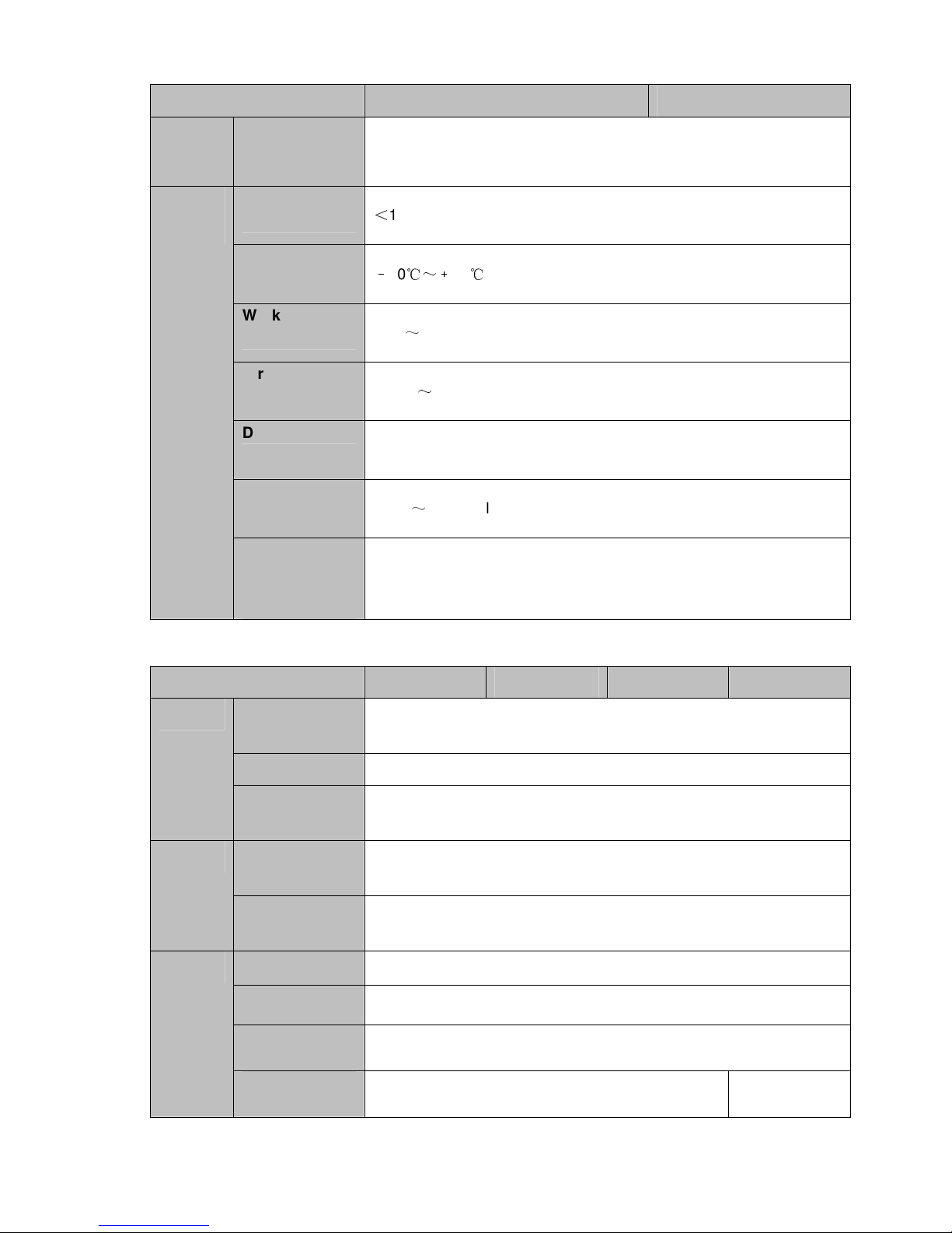
1.3.1 NVR100/100-P Series
Model 100 Series 100-P Series
System System
Resources
OS
Operation
Interface
Decode Video Decode
4/8-ch series product support 4/8 HD connection respectively. Total
bandwidth supports 28/56Mbps respectively.
Embedded Linux real-time operation system
WEB/Local GUI
H.264/MJPEG
2
Page 15

Model 100 Series 100-P Series
Type
Decode
Capability
Video Video Input
Video Output
HDMI
Window Split
Audio Audio Input
Audio Output
Audio
Compression
Standard
Max 2-ch 1080P 30fps or 4-ch 720P 30fps or 8-ch D1 30fps
4/8-ch network compression video input
1-channel VGA analog video output
1-ch HDMI output. Version number is 1.4
1/4/8-window
N/A
N/A
G.711a
Alarm Alarm Input
Alarm Output
Funciton Storage
Multiple-Chann
el Playback
Port and
RS232 Port
Indicator
RS485 Port
USB Port
N/A
N/A
1 built-in 2.5-inch SATA port
Max 8-channel D1 or 4-channel 720P or 2-channel 1080P playback
N/A
N/A
2 peripheral USB2.0 ports.
3
Page 16

Model 100 Series 100-P Series
Network
Connection
1 RJ45 10/100Mbps self-adaptive Ethernet port.
PoE
N/A 4
Power Port
1 power socket. Power adapter
power supplying mode. DC 5V
2A power.
1 power socket. Power adapter
power supplying mode. DC 48V
1.25A power.
Power Button
N/A
Power On-off
Button
N/A
IR Receiver
Window
N/A
General
Clock
Indicator Light
Power
Consumption
Working
Temperature
Working
Humidity
Air pressure
Dimension
Weight
Built-in clock.
N/A
<
10W (Exclude HDD)
﹣10℃~﹢55℃
10℅~90℅
86kPa~106kPa
191.8mm×128.2mm×35.8mm
0.32kg~0.36kg (Exclude HDD)
Installation
Mode
1.3.2 NVR11/11-P Series
Model 11 Series 11-P Series
Desk installation
4
Page 17

Model 11 Series 11-P Series
4/8-ch series product support 4/8 HD connection respectively. Total
System System
bandwidth supports 28/56Mbps respectively.
Resources
OS
Operation
Interface
Decode Video Decode
Type
Decode
Capability
Video Video Input
Video Output
HDMI
Embedded Linux real-time operation system
WEB/Local GUI
H.264/MJPEG
Max 2-ch 1080P 30fps or 4-ch 720P 30fps or 8-ch D1 30fps
4/8-ch network compression video input
1-channel VGA analog video output
1-ch HDMI output. Version number is 1.4
Window Split 1/4/8-window
Audio Audio Input
Audio Output
Audio
Compression
Standard
Alarm Alarm Input
Alarm Output
Funciton Storage
1-ch bidirectional talk input
1-ch bidirectional talk output
G.711a
N/A
N/A
1 built-in SATA port
5
Page 18

Model 11 Series 11-P Series
Port and
Indicator
Multiple-Chann
el Playback
RS232 Port
RS485 Port
USB Port
Network
Connection
PoE
Power Port
Max 8-channel D1 or 4-channel 720P or 2-channel 1080P playback
N/A
N/A
2 peripheral USB2.0 ports.
1 RJ45 10/100Mbps self-adaptive Ethernet port.
N/A 4
1 power socket. Power adapter
power supplying mode. DC 12V
power.
1 power socket. Power adapter
power supplying mode. DC 48V
power.
General
Power Button
Power On-off
Button
IR Receiver
Window
Clock
Indicator Light
Power
Consumption
Working
Temperature
Working
Humidity
N/A
N/A
N/A
Built-in clock.
One power status indicator light.
One network status indicator light.
One HDD status indicator light.
<
10W (Exclude HDD)
﹣10℃~﹢55℃
10℅~90℅
Air pressure
86kPa~106kPa
6
Page 19

Model 11 Series 11-P Series
Dimension
205mm×206.75mm×45.2mm
Weight
0.5kg~1kg (Exclude HDD)
Installation
Desk installation
Mode
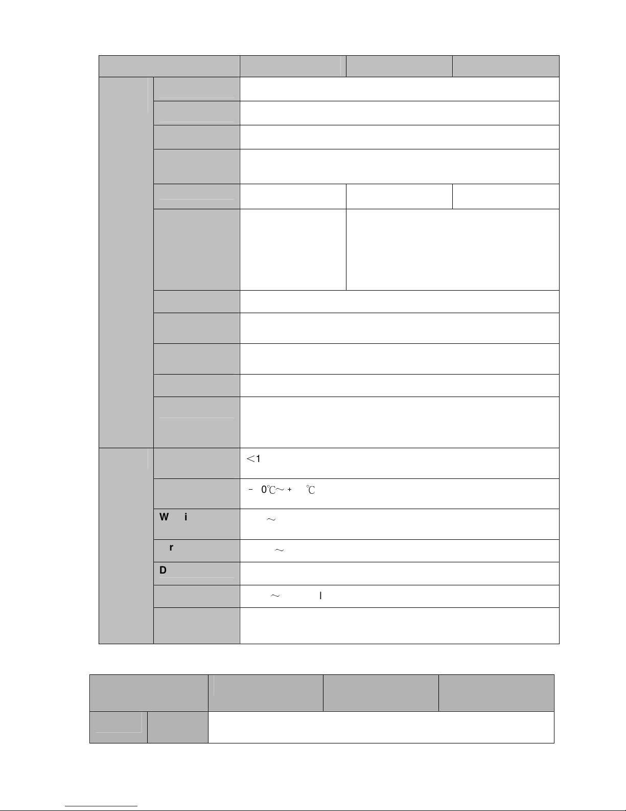
1.3.3 NVR11H/11H-P Series
Model 11H Series 11H-P Series
4/8-ch series product support 4/8 HD connection respectively. Total
System System
Resources
OS
Operation
Interface
Decode Video Decode
Type
bandwidth supports 28/56Mbps respectively.
Embedded Linux real-time operation system
WEB/Local GUI
H.264/MJPEG
Decode
Capability
Video Video Input
Video Output
HDMI
Window Split
Audio Audio Input
Audio Output
Max 2-ch 1080P 30fps or 4-ch 720P 30fps or 8-ch D1 30fps
4/8-ch network compression video input
1-channel VGA analog video output
1-ch HDMI output. Version number is 1.4
1/4/8-window
1-ch bidirectional talk input
1-ch bidirectional talk output
7
Page 20

Model 11H Series 11H-P Series
Audio
G.711a
Compression
Standard
Alarm Alarm Input N/A
Alarm Output
Funciton Storage
Multiple-Chann
N/A
1 built-in SATA port
Max 8-channel D1 or 4-channel 720P or 2-channel 1080P playback
el Playback
Port and
RS232 Port N/A
Indicator
RS485 Port
N/A
USB Port
Network
Connection
PoE
Power Port
Power Button
Power On-off
Button
IR Receiver
Window
2 peripheral USB2.0 ports.
1 RJ45 10/100Mbps self-adaptive Ethernet port.
N/A 4
1 power socket. Power adapter
power supplying mode. DC 12V
power.
1 power socket. Power adapter
power supplying mode. DC 48V
power.
N/A
N/A
N/A
Clock
Built-in clock.
8
Page 21
Model 11H Series 11H-P Series
One power status indicator light.
Indicator Light
One network status indicator light.
One HDD status indicator light.
Power
General
Consumption
<
10W (Exclude HDD)
Working
Temperature
﹣10℃~﹢55℃
Working
Humidity
10℅~90℅
Air pressure
86kPa~106kPa
Dimension
325mm×250.58mm×51mm
Weight
0.5kg~1kg (Exclude HDD)
Installation
Desk installation
Mode
1.3.4 NVR41/41-P/41-8P/41-W Series
Model 41 Series 41-P Series 41-8P Series 41-W Series
System System
Resources
OS
Operation
Interface
Decode Video Decode
Type
Decode
Capability
Video Video Input 4/8/16-ch network compression video input
Video Output
4/8/16-ch series product support 4/8/16 HD connection respectively.
Total bandwidth supports 28/56/80Mbps respectively.
Embedded Linux real-time operation system
WEB/Local GUI
H.264/MJPEG/MJPEG4
Max 2-ch 5M 25fps or 4-ch 3M 25fps or 4-ch 1080P 30fps
or 8-ch 720P 30fs
1-channel VGA analog video output
HDMI
Window Split
1-ch HDMI output. Version number is 1.4
1/4/8/9/16-window 1/4-window
9
Page 22

Model 41 Series 41-P Series 41-8P Series 41-W Series
Audio Audio Input
Audio Output
Audio
1-ch bidirectional talk input
1-ch bidirectional talk output
G.711a
Compression
Standard
Alarm Alarm Input
Alarm Output
N/A
N/A
Funciton Storage 1 built-in SATA port
Multiple-Chann
Max 4-channel 1080P playback
el Playback
N/A Yes
N/A
Port and
WIFI AP
RS232 Port
Indicator
RS485 Port
USB Port
Network
N/A
2 peripheral USB2.0 ports.
1 RJ45 10/100Mbps self-adaptive Ethernet port.
Connection
PoE Port
N/A 4 8 N/A
General
Power Port
Power Button
Power On-off
Button
IR Receiver
Window
Clock
Indicator Light
Power
Consumption
Working
Temperature
1 power
socket. Power
adapter power
1 power socket. Power adapter
power supplying mode. DC 48V
power.
supplying
mode. DC 12V
power.
1 button
N/A
N/A
Built-in clock.
One power status indicator light.
One network status indicator light.
One HDD status indicator light.
<
10W (Exclude HDD)
﹣10℃
~﹢55℃
1 power
socket. Power
adapter power
supplying
mode. DC 12V
power.
10
Page 23

ch 1080P 30fps
Model 41 Series 41-P Series 41-8P Series 41-W Series
Working
10℅~90℅
Humidity
Air pressure
Dimension 205mm×206.75mm×45.2mm 270mm×204m
Weight
Installation
86kPa~106kPa
0.5kg~1kg (Exclude HDD)
Desk installation
m×42mm
205mm×206.7
5mm×45.2mm
Mode
1.3.5 NVR41H/41H-P/41H-8P Series
Model 41H Series 41H-P Series 41H-8P Series
System System
Resources
OS
Operation
Interface
Decode Video Decode
Type
4/8/16-ch series product support 4/8/16 HD connection respectively.
Total bandwidth supports 28/56/80Mbps respectively.
Embedded Linux real-time operation system
WEB/Local GUI
H.264/MJPEG/MJPEG4
Decode
Capability
Video Video Input
Video Output
HDMI
Window Split
Audio Audio Input
Audio Output
Audio
Compression
Standard
Alarm Alarm Input
Alarm Output
Funciton Storage
Max 2-ch 5M 25fps or 4-ch 3M 25fps or 4or 8-ch 720P 30fs
4/8/16-ch network compression video input
1-channel VGA analog video output
1-ch HDMI output. Version number is 1.4
1/4/8/9/16-window
1-ch bidirectional talk input
1-ch bidirectional talk output
G.711a
N/A 2-channel
N/A 2-channel
1 built-in SATA port
Multiple-Chann
el Playback
Max 4-channel 1080P playback
11
Page 24
Model 41H Series 41H-P Series 41H-8P Series
Port and
Indicator
RS232 Port
RS485 Port
USB Port
Network
Connection
PoE Port
Power Port
Power Button
Power On-off
Button
IR Receiver
Window
Clock
N/A
N/A
2 peripheral USB2.0 ports.
1 RJ45 10/100Mbps self-adaptive Ethernet port.
N/A 4 8
1 power socket.
Power adapter
1 power socket. Power adapter power
supplying mode. DC 48V power.
power supplying
mode. DC 12V
power.
1 button
N/A
N/A
Built-in clock.
Indicator Light
One power status indicator light.
One network status indicator light.
One HDD status indicator light.
General
Power
<
10W (Exclude HDD)
Consumption
Working
﹣10℃
~﹢
55 ℃
Temperature
Working
10℅~90℅
Humidity
Air pressure
Dimension
Weight
Installation
86kPa~106kPa
325mm×250.58mm×51mm
0.5kg~1kg (Exclude HDD)
Desk installation
Mode
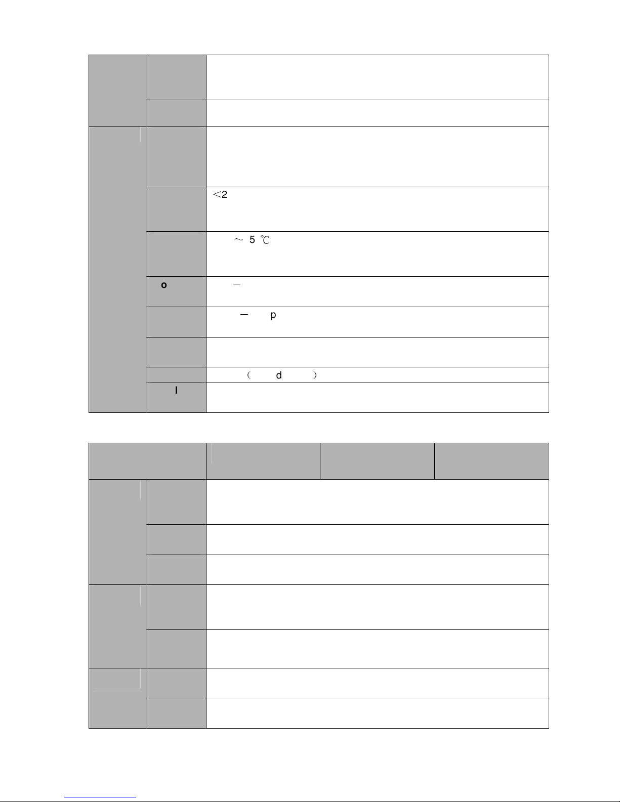
1.3.6 NVR42/42-P/42-8P Series
Model 42 Series 42-P Series 42-8P Series
System
System
Resource
4/8/16/32-channel series product support 4/8/16/32-channel HD connection
respectively. Main stream bandwidth supports 40/80/160/160Mbps
12
Page 25

s
respectively.
Operation
System
Operation
Interface
Decode
Video
Compres
sion
Decode
Capacity
Video
Video
Input
Video
Output
HDMI 1-ch HDMI output. Version number is 1.4
Window
Split
Audio
Audio
Input
Audio
Output
Audio
Compres
sion
Alarm
Alarm
Input
Alarm
Output
Function Storage
Embedded Linux real-time operation system
WEB/Local GUI
H.264/MJPEG/MPEG4
Max supports 16-channel D1, or 8-channel 720P, or 4-channel 1080P, or
4*3M or 2*5M decode.
4/8/16/32-ch network compression video input
1-channel VGA analog video output.
1/4/8/9/16-window
1-ch bidirectional talk input
1-ch bidirectional talk output
G.711a
4-ch alarm input
2-ch alarm output
2 built-in SATA ports.
Multiple-c
hannel
Playback
Port and
Indicator
RS232
Port
RS485
port
USB2.0
Port
Network
Connecti
on
Max 8-channel 720P/4-channel 1080P playback at the same time.
One RS232 port to debug transparent COM data.
One RS485 port to control PTZ. Support various protocols.
Three peripheral USB2.0 ports.
1 RJ45 10/100/1000Mbps self-adaptive Ethernet port.
13
Page 26

Power
Port
Power
One power port,
power adapter. Input
DC 12V.
One button. At the rear panel.
Two power ports. Input
DC 12V/DC 48V.
One power ports.
Input 100-240V
,
47~63Hz.
Button
Power
One button. At the front-panel.
On-off
Button
IR
Support IR remote control
Receiver
Window
Clock
Indicator
Light
Built-in clock.
One power status indicator light.
One network status indicator light.
One HDD status indicator light.
General Power
<
30W(Exclude HDD)
Consump
tion
Working
-10℃~+55℃
Temperat
ure
Working
10℅-90℅
Humidity
Air
86kpa-106kpa
pressure
Dimensio
375mm×287mm×52mm 375mm×287mm×52mm 295mm×275mm×47m
n
Weight 1.5kg~2.5kg(Exclude HDD)
Installatio
Desk installation
n
1.3.7 NVR42-4K/42-8P-4K Series
Model
NVR42-4K Series NVR42-8P-4K Series
m
System
System
Resource
s
Operation
System
Operation
Interface
Video
Decode
Compres
sion
8/16/32-channel series product support 8/16/32-channel HD connection
respectively. The main stream bandwidth supports 48/96/192Mbps.
Embedded Linux real-time operation system
WEB/Local GUI
H.264/MJPEG/MPEG4
14
Page 27

arm output
Video
Decode
Capacity
Video
Input
Video
Output
HDMI
H.264: Max supports 16-channel D1, or 8-channel 720P, 4-channel 1080P
or 1-channel 4K decode.
H.265: Max supports 16-channel D1, or 8-channel 720P, 4-channel 1080P
or 1-channel 4K decode.
8/16/32-ch network compression video input
1-channel VGA analog video output.
1-ch HDMI output. Version number is 1.4
Window
Split
Audio
Audio
Input
Audio
Output
Audio
Compres
sion
Alarm
Alarm
Input
Alarm
Output
Function Storage
Multiple-c
hannel
Playback
Port and
Indicator
RS232
Port
RS485
port
1/4/8/9/16-window
1-ch bidirectional talk input
1-ch bidirectional talk output
G.711a, G.711u, PCM, G726
8-ch alarm input
3-ch al
Relay output. Relay (DC 30V /1A,AC 125V/0.5A(Activation output))
Including one controllable DC +12V output.
2 built-in SATA ports.
Max 8-channel 720P/4-channel 1080P/1-channel 4K playback at the same
time.
One RS232 port to debug transparent COM data.
One RS485 port to control PTZ. Support various protocols.
USB Port
2 peripheral USB ports: One USB2.0 at the front panel and one USB3.0 at
the rear panel.
Network
One RJ45 10/100/1000Mbps self-adaptive Ethernet port.
Connecti
on
Power
Port
One power socket. Power adapter
power supplying. Input DC 12V
power.
Power
One button. At the rear panel.
Button
Power
N/A
On-off
Button
One power port. Input 100-240V
47~63Hz.
,
15
Page 28
IR
N/A
Receiver
Window
Clock
Built-in clock.
General Indicator
Light
One power status indicator light.
One network status indicator light.
One HDD status indicator light.
One device running status indicator light.
Power
<
20W(Exclude HDD)
Consump
tion
Working
-10℃~+55℃
Temperat
ure
Working
10℅-90℅
Humidity
Air
86kpa-106kpa
pressure
Dimensio
1U, 375mm(W) × 49.8mm(H) × 250mm(D)
n
Weight 1.65kg(Exclude HDD)
Installatio
Desk/rack installation
n
1.3.8 NVR44/44-8P/44-16P Series
Model
NVR44 Series NVR44-8P Series NVR44-16P Series
System
Decode
Video
System
Resource
s
Operation
System
Operation
Interface
Video
Compres
sion
Decode
Capacity
Video
Input
Video
Output
8/16/32-channel series product support 8/16/32-channel HD connection
respectively. The main stream bandwidth supports 200Mbps.
Embedded Linux real-time operation system
WEB/Local GUI
H.264/MJPEG/MPEG4
Max supports 16-channel D1, or 8-channel 720P, or 4-channel 3M or 2*5M
decode.
8/16/32-ch network compression video input
1-channel VGA analog video output.
16
Page 29

ch alarm output
at the rear panel.
HDMI
1-ch HDMI output. Version number is 1.4
Window
Split
Audio
Audio
Input
Audio
Output
Audio
Compres
sion
Alarm
Alarm
Input
Alarm
Output
Function Storage
Multiple-c
hannel
Playback
Port and
Indicator
RS232
Port
RS485
port
1/4/8/9/16-window
1-ch bidirectional talk input
1-ch bidirectional talk output
G.711a
16-ch alarm input
4-
Relay output. Relay (DC 30V /1A,AC 125V/0.5A(Activation output))
Including one controllable DC +12V output.
4 built-in SATA ports. 1 external eSATA port.
Max 8-channel 720P/4-channel 1080P playback at the same time.
One RS232 port to debug transparent COM data.
One RS485 port to control PTZ. Support various protocols.
USB2.0
Port
Network
Connecti
on
Power
Port
Power
Button
Power
On-off
Button
IR
Receiver
Window
Clock
General Indicator
Light
2 peripheral USB2.0 ports. One at the front panel and one
One RJ45 10/100/1000Mbps self-adaptive Ethernet port.
One power port. Input 100-240V,50~60Hz.
One button. At the rear panel.
One button. At the front-panel.
Support IR remote control
Built-in clock.
One power status indicator light.
One network status indicator light.
One HDD status indicator light.
17
Page 30

Power
<
30W(Exclude HDD)
Consump
tion
Working
-10℃~+55℃
Temperat
ure
Working
10℅-90℅
Humidity
Air
86kpa-106kpa
pressure
Dimensio
1.5U, 440mm × 460mm × 68mm
n
Weight 5kg~6kg(Exclude HDD)
Installatio
Desk installation
n
1.3.9 NVR44-4K Series
Specifications NVR44-4K
Industrial embedded micro processor
Embedded LINUX system
Max 8-channel×1080P connection,
WEB, local GUI
1-ch MIC bidirectional talk audio input
System
Main Processor
Operation System
System
Resources
User Interface
Audio Input
Audio
Parameters
Video
Parameters
Alarm
Parameters
Decode
Parameters
Audio Output
Audio
Compression
Standard
Video Input
Video Output
1-ch MIC bidirectional talk audio output
G.711a, G.711u, PCM, G726
8/16/32-ch network compression video input
1-channel VGA
2-channel HDMI.
Video
Compression
H.264
Standard
Window Split
Mode
Alarm Input
Alarm Output
The 1st screen: 1/4/8/9/16-screen.
The 2nd screen: 1/4-screen.
16-channel
8-channel relay output
Decode Type MPEG4,H.264,H.265
Decode Capability
16-channel×D1;8-channel×720P, 4-channel 1080P;1-channel
4K
18
Page 31

Functions
Network
Function
Record Mode
Multi-Channel
Playback
Motion Detect
Privacy Mask
Record Mode
Backup Mode
Network Protocol
SATA Port
eSATA Port
RS232 Port
RS485 Port
USB Port
HDMI Port
Manual recording, motion detection recording, schedule
recording and alarm recording.
Priority: Manual recording>card number recording-> alarm
recording>motion detection recording>schedule recording.
Max support 64M(H265&H264 1:1) playback at the same
time.
Each screen supports 396/330((PAL 22×18, NTSC 22×15)
detection zones. Various sensitivity levels.
Each channel supports 4 privacy mask zones.
Overwrite
Flash disk, eSATA, DVD burner.
IPv4/IPv6/HTTP/UPnP/NTP/SADP/SNMP/PPPoE/DNS/FTP/ON
VIF/PSIA
4 SATA Ports
1 eSATA port
1 RS232 port. To debug and transmit COM data.
1 RS485 port. To control peripheral PTZ and etc. Support
various protocols.
1 USB 2.0 port at the front panel and 2 USB3.0 ports at the
rear panel.
2 HDMI ports
Network Port
Power On-off
Button
2 RJ45 10/100/1000Mbps self-adaptive Ethernetet ports+2
1000Mbps self-adaptive fiber ports
One at the rear panel.
4 indicator lights.
1 system running status indicator light
Indicator Light
1 HDD indicator light
1 network status indicator light
1 power status indicator light
AC100~240V
General series: <17W(No HDD),
PoE series: <26.5W (No HDD),
0℃~50℃
××××
440×76×405mm
General
Parameters
Power
Power
Consumption
Working
Temperature
Working Humidity 10%~90%(No condensation)
Dimensions (W
H
××××
D)
Weight General series:4.35 kg(No HDD),
PoE series: 4.65kg (No HDD),
Installation Mode
Rack/desktop
1.3.10 NVR48-4K Series
Specifications NVR48-4K
System Main Processor
Industrial embedded micro processor
19
Page 32

Operation System
System
Resources
User Interface
Audio Input
Embedded LINUX system
Max 8-channel×1080P connection,
WEB, local GUI
1-ch MIC bidirectional talk audio input
Audio
Parameters
Video
Parameters
Alarm
Parameters
Decode
Parameters
Functions
Network
Function
Audio Output
Audio
Compression
Standard
Video Input
Video Output
1-ch MIC bidirectional talk audio output
G.711a, G.711u, PCM, G726
8/16/32-ch network compression video input
1-channel VGA
2-channel HDMI.
Video
Compression
H.264
Standard
Window Split
Mode
Alarm Input
The 1st screen: 1/4/8/9/16-screen.
The 2nd screen: 1/4-screen.
16-channel
Alarm Output 6-channel relay output
Decode Type MPEG4,H.264,H.265
Decode Capability
16-channel×D1;8-channel×720P, 4-channel 1080P;1-channel
4K
Record Mode Manual recording, motion detection recording, schedule
recording and alarm recording.
Priority: Manual recording>card number recording-> alarm
recording>motion detection recording>schedule recording.
Multi-Channel
Playback
Motion Detect
Max support 64M(H265&H264 1:1) playback at the same
time.
Each screen supports 396/330((PAL 22×18, NTSC 22×15)
detection zones. Various sensitivity levels.
Privacy Mask
Record Mode
Backup Mode
Network Protocol
SATA Port
eSATA Port
RS232 Port
RS485 Port
USB Port
HDMI Port
Each channel supports 4 privacy mask zones.
Overwrite
Flash disk, eSATA, DVD burner.
IPv4/IPv6/HTTP/UPnP/NTP/SADP/SNMP/PPPoE/DNS/FTP/
ONVIF/PSIA
8 SATA Ports
1 eSATA port
1 RS232 port. To debug and transmit COM data.
1 RS485 port. To control peripheral PTZ and etc. Support
various protocols.
2 USB 2.0 ports at the front panel and 2 USB3.0 ports at the
rear panel.
2 HDMI ports
20
Page 33

Network Port
Power On-off
Button
2 RJ45 10/100/1000Mbps self-adaptive Ethernetet ports+2
1000Mbps self-adaptive fiber ports
One at the rear panel.
4 indicator lights.
1 system running status indicator light
Indicator Light
1 HDD indicator light
1 network status indicator light
1 power status indicator light
AC100~240V
General series: <18.8W(No HDD),
PoE series: <27.9W (No HDD),
0℃~50℃
××××
440×95×445mm
General
Parameters
Power
Power
Consumption
Working
Temperature
Working Humidity 10%~90%(No condensation)
Dimensions (W
H
××××
D)
Weight General series:6.6 kg(No HDD),
PoE series: 6.75kg (No HDD),
Installation Mode
Rack/desktop
1.3.11 NVR48/48-16P Series
Model NVR48 Series NVR48-16P Series
System
Decode
Video
System
Resource
s
Operation
System
Operation
Interface
Video
Compres
sion
Decode
Capacity
Video
Input
Video
Output
HDMI
Window
Split
8/16/32-channel series product support 8/16/32-channel HD connection
respectively. The main stream bandwidth supports 200Mbps.
Embedded Linux real-time operation system
WEB/Local GUI
H.264/MJPEG/MPEG4
Max supports 16-channel D1, or 8-channel 720P, or 4-channel 3M or 2*5M
decode.
8/16/32-ch network compression video input
1-channel VGA analog video output.
1-ch HDMI output. Version number is 1.4
1/4/8/9/16-window
21
Page 34

ch alarm output
at the rear panel.
Audio
Audio
Input
Audio
Output
Audio
Compres
sion
Alarm
Alarm
Input
Alarm
Output
Function Storage
1-ch bidirectional talk input
1-ch bidirectional talk output
G.711a
16-ch alarm input
4-
Relay output. Relay (DC 30V /1A,AC 125V/0.5A(Activation output))
Including one controllable DC +12V output.
4 built-in SATA ports. 1 external eSATA port.
Port and
Indicator
Multiple-c
hannel
Playback
RS232
Port
RS485
port
USB2.0
Port
Network
Connecti
on
Power
Port
Power
Button
Power
On-off
Button
IR
Receiver
Window
Clock
Max 8-channel 720P/4-channel 1080P playback at the same time.
One RS232 port to debug transparent COM data.
One RS485 port to control PTZ. Support various protocols.
3 peripheral USB2.0 ports. Two at the front panel and one
One RJ45 10/100/1000Mbps
self-adaptive Ethernet port.
One RJ45 10/100/1000Mbps
self-adaptive Ethernet port.
One power port. Input 100-240V,50~60Hz.
One button. At the rear panel.
One button. At the front-panel.
Support IR remote control
Built-in clock.
General Indicator
Light
One power status indicator light.
One network status indicator light.
One HDD status indicator light.
Power
<
30W(Exclude HDD)
Consump
tion
Working -10℃~+55℃
22
Page 35

ch alarm output
Temperat
ure
Working
10℅-90℅
Humidity
Air
86kpa-106kpa
pressure
Dimensio
440mm × 460mm × 89mm
n
Weight 5.5kg~6.5kg(Exclude HDD)
Installatio
Desk installation
n
1.3.12 NVR72/72-8P Series
Model NVR72 Series NVR72-8P Series
System
Decode
Video
Audio
Alarm
System
Resource
s
Operation
System
Operation
Interface
Video
Compres
sion
Decode
Capacity
Video
Input
Video
Output
HDMI
Window
Split
Audio
Input
Audio
Output
Audio
Compres
sion
Alarm
Input
Alarm
8/16/32/64-channel series product support 8/16/32/64-channel HD
connection respectively. The main stream bandwidth supports
48/96/192/192Mbps.
Embedded Linux real-time operation system
WEB/Local GUI
H.264/MJPEG
Max supports 32-channel D1, or 16-channel 720P, or 8-channel 1080P
decode.
8/16/32/64-ch network compression video input
1-channel VGA analog video output.
1-ch HDMI output. Version number is 1.4
1/4/8/9/16/25/36-window
1-ch bidirectional talk input
1-ch bidirectional talk output
G.711a
8-
3-ch alarm output
23
Page 36

Including one controllable DC +12V output.
Output Relay output. Relay (DC 30V/1A,AC 125V/0.5A(Activation output))
Function Storage
Multiple-c
hannel
Playback
Port and
Indicator
RS232
Port
RS485
port
USB2.0
Port
Network
Connecti
on
Power
Port
Power
Button
Power
On-off
Button
IR
Receiver
Window
Clock
2 built-in SATA ports.
Max 16-channel 720P/8-channel 1080P playback at the same time.
One RS232 port to debug transparent COM data.
One RS485 port to control PTZ. Support various protocols.
2 peripheral USB2.0 ports. One at the front panel and one at the rear panel.
1 RJ45 10/100Mbps self-adaptive Ethernet port.
One power port, power adapter.
Input DC 12V.
One power port. Input 100-240V
47~63Hz.
,
One button. At the rear panel.
One button. At the front-panel.
Support IR remote control
Built-in clock.
General Indicator
Light
Power
Consump
tion
Working
Temperat
ure
Working
Humidity
Air
pressure
Dimensio
n
Weight 1.5kg~2.5kg (Exclude HDD)
Installatio
One power status indicator light.
One network status indicator light.
One HDD status indicator light.
<
30W(Exclude HDD)
-10℃~+55℃
10℅-90℅
86kpa-106kpa
1U case. 295mm×275mm×47mm
Desk installation
24
Page 37

ch alarm output
n
1.3.13 NVR74/74-8P/74-16P Series
Model
NVR74 Series NVR74-8P Series NVR74-16P Series
System
System
Resource
s
Operation
System
Operation
Interface
Decode
Video
Compres
sion
Decode
Capacity
Video
Video
Input
Video
Output
HDMI
Window
Split
Audio
Audio
Input
Audio
Output
Audio
Compres
sion
Alarm
Alarm
Input
Alarm
Output
Function Storage
8/16/32/64-channel series product support 8/16/32/64-channel HD
connection respectively. The main stream bandwidth supports
48/96/192/192Mbps.
Embedded Linux real-time operation system
WEB/Local GUI
H.264/MJPEG
Max supports 32-channel D1, or 16-channel 720P, or 8-channel 1080P
decode.
8/16/32/64-ch network compression video input
1-channel VGA analog video output.
1-ch HDMI output. Version number is 1.4
1/4/8/9/16/25/36-window
1-ch bidirectional talk input
1-ch bidirectional talk output
G.711a
16-ch alarm input
6-
Relay output. Relay (DC 30V /1A,AC 125V/0.5A(Activation output))
Including one controllable DC +12V output.
4 built-in SATA ports. 1 external eSATA port.
Multiple-c
Max 16-channel 720P/8-channel 1080P playback at the same time.
hannel
Playback
Port and
Indicator
RS232
Port
One RS232 port to debug transparent COM data.
25
Page 38

RS485
port
One RS485 port to control PTZ. Support various protocols.
USB2.0
Port
Network
Connecti
on
Power
Port
Power
Button
Power
On-off
Button
IR
Receiver
Window
Clock
General Indicator
Light
3 peripheral USB2.0 ports. One at the front panel and two at the rear panel.
Two RJ45 10/100Mbps
self-adaptive Ethernet
ports.
One power port. Input 100-240V,50~60Hz.
One button. At the rear panel.
One button. At the front-panel.
Support IR remote control
Built-in clock.
One power status indicator light.
One network status indicator light.
One HDD status indicator light.
One RJ45 10/100Mbps self-adaptive Ethernet
port.
Power
Consump
tion
Working
Temperat
ure
Working
Humidity
Air
pressure
Dimensio
n
Weight 5kg~6kg(Exclude HDD)
Installatio
n
<
30W(Exclude HDD)
-10℃~+55℃
10℅-90℅
86kpa-106kpa
1.5U, 440mm × 460mm × 68mm
Desk installation
1.3.14 NVR78/78-16P/78-RH Series
Model
NVR78 Series NVR78-16P Series NVR78-RH Series
System
System
Resource
8/16/32/64-channel series product support 8/16/32/64-channel HD
connection respectively. The main stream bandwidth supports
26
Page 39

s
48/96/192/192Mbps.
Operation
System
Operation
Interface
Decode
Video
Compres
sion
Decode
Capacity
Video
Video
Input
Video
Output
HDMI 1-ch HDMI output. Version number is 1.4 2-ch HDMI output
Window
Split
Audio
Audio
Input
Audio
Output
Audio
Compres
sion
Alarm
Alarm
Input
Alarm
Output
Function Storage
Multiple-c
hannel
Playback
Port and
Indicator
RS232
Port
RS485
port
Embedded Linux real-time operation system
WEB/Local GUI
H.264/MJPEG
Max supports 32-channel D1, or 16-channel 720P, or 8-channel 1080P
decode.
8/16/32/64-ch network compression video input
1-channel VGA analog video output.
(from different video
sources)
1/4/8/9/16/25/36-window
1-ch bidirectional talk input
1-ch bidirectional talk output
G.711a
16-ch alarm input
6-ch alarm output
Relay output. Relay (DC 30V/1A,AC 125V/0.5A(Activation output))
Including one controllable DC +12V output.
8 built-in SATA ports.
1 external eSATA port.
8 built-in SATA ports at
the front panel.
Support hot swap,
Raid0, Raid1, Raid5,
Raid6.
1 external eSATA port.
Max 16-channel 720P/8-channel 1080P playback at the same time.
One RS232 port to debug transparent COM data.
One RS485 port to control PTZ. Support various protocols.
27
Page 40

the front panel and two at the rear panel.
USB2.0
Port
Network
Connecti
on
Power
Port
4 peripheral USB2.0 ports. Two at
Two RJ45 10/100/1000
Mbps self-adaptive
Ethernet ports.
One power port. Input 100-240V,50~60Hz.
One RJ45 10/100/1000
Mbps self-adaptive
Ethernet port.
Two RJ45 10/100/1000
Mbps self-adaptive
Ethernet ports.
Power
Button
Power
On-off
Button
IR
Receiver
Window
Clock
General Indicator
Light
Power
Consump
tion
Working
Temperat
ure
Working
Humidity
Air
pressure
Dimensio
n
Weight 5.5kg~6.5kg(Exclude HDD) 8.5kg~9.5kg(Exclude
Installatio
n
One button. At the rear panel.
One button. At the front-panel.
Support IR remote control
Built-in clock.
One power status indicator light.
One network status indicator light.
One HDD status indicator light.
<
35W(Exclude HDD)
-10℃~+55℃
10℅-90℅
86kpa-106kpa
440mm×460mm×89mm 444mm×430mm×89m
Desk installation
1.3.15 NVR70/70-R Series
Model
NVR70 Series NVR70-R Series
m
HDD)
System
System
Resource
s
8/16/32/64-channel series product support 8/16/32/64-channel HD
connection respectively. The main stream bandwidth supports
48/96/192/192Mbps.
28
Page 41

ch alarm input
trollable DC +12V output.
Decode
Operation
System
Operation
Interface
Video
Compres
sion
Decode
Capacity
Embedded Linux real-time operation system
WEB/Local GUI
H.264/MJPEG
Max supports 32-channel D1, or 16-channel 720P, or 8-channel 1080P
decode.
Video
Video
Input
Video
Output
HDMI
Window
Split
Audio
Audio
Input
Audio
Output
Audio
Compres
sion
Alarm
Alarm
Input
Alarm
Output
Function Storage
Multiple-c
hannel
Playback
Port and
Indicator
RS232
Port
RS485
port
8/16/32/64-ch network compression video input
1-channel VGA analog video output.
1-ch HDMI output. 2-ch HDMI output (from different
video sources)
1/4/8/9/16/25/36-window
1-ch bidirectional talk input
1-ch bidirectional talk output
G.711a
16-
6-ch alarm output
Relay output. Relay (DC 30V/1A,AC 125V/0.5A(Activation output))
Including one con
16 built-in SATA ports at the front
panel. Support removable HDD
installation mode.
1 external eSATA port.
16 built-in SATA ports at the front
panel. Support hot swap, Raid0,
Raid1, Raid5, Raid6.
1 external eSATA port.
Max 16-channel 720P/8-channel 1080P playback at the same time.
One RS232 port to debug transparent COM data.
One RS485 port to control PTZ. Support various protocols.
USB2.0
4 peripheral USB2.0 ports. Two at the front panel and two at the rear panel.
Port
Network
Two RJ45 10/100Mbps self-adaptive Ethernet ports.
Connecti
on
29
Page 42

Power
One power port. Input 100V~240V,50~60Hz.
Port
Power
Button
Power
On-off
Button
IR
Receiver
Window
Clock
General Indicator
Light
Power
Consump
tion
Working
Temperat
ure
Working
Humidity
Air
pressure
Dimensio
n
Weight 10.5kg~11.5kg(Exclude HDD)
Installation Desk installation
One button. At the rear panel.
One button. At the front-panel.
Support IR remote control
Built-in clock.
One power status indicator light.
One network status indicator light.
One HDD status indicator light.
<
35W(Exclude HDD)
-10℃~+55℃
10℅-90℅
86kpa-106kpa
3U case: 448mm×490mm×133.2mm
1.3.16 NVR42V-8P Series
Model NVR42V-8P
System
Decode
System
Resources
Operation
System
Operation
Interface
Video
Compression
8/16/32-channel series product support 8/16/32-channel HD connection
respectively. Main stream bandwidth supports 80/160/160Mbps
respectively.
Embedded Linux real-time operation system
WEB/Local GUI
H.264/MJPEG/MPEG4
30
Page 43

Decode
Capacity
Max supports 16-channel D1, or 8-channel 720P, or 4-channel 1080P,
or 4*3M or 2*5M decode.
Video
Video Input
Video Output
HDMI
Window Split
Audio
Audio Input
Audio Output
Audio
Compression
Alarm
Alarm Input
Alarm Output
Function Storage
Multiple-chann
el Playback
Port
RS232 Port
and
Indicato
RS485 port
r
USB Port
Network
Connection
Power Port
8/16/32-ch network compression video input
1-channel VGA analog video output.
1-ch HDMI output. Version number is 1.4
1/4/8/9/16-window
1-ch bidirectional talk input
1-ch bidirectional talk output
G.711a
2-ch alarm input
1-ch alarm output
2 built-in SATA ports.
Max 8-channel 720P/4-channel 1080P playback at the same time.
N/A
N/A
Two USB2.0 ports at the front panel and one USB3.0 port at the rear
panel. .
1 RJ45 10/100/1000Mbps self-adaptive Ethernet port and 8 PoE ports.
One power port. Input DC 53V--2.3A
Power Button
Power On-off
Button
IR Receiver
Window
Clock
Indicator Light
General Power
Consumption
Working
Temperature
Working 10℅-90℅
One button. At the rear panel.
N/A
Support IR remote control
Built-in clock.
One power status indicator light.
One network status indicator light.
One HDD status indicator light.
One alarm status indicator light.
<
30W(Exclude HDD)
-10℃~+55℃
31
Page 44

Humidity
Air pressure 86kpa-106kpa
Dimension
100mm×220mm×146mm
Weight 1.5kg~2.5kg(Exclude HDD)
Installation
Desk installation
32
Page 45

2 Front Panel and Rear Panel
2.1 Front Panel
2.1.1 NVR11/11-P/41/41-P/41-W Series
The front panel is shown as in Figure 2-1.
Figure 2-1
Please refer to the following sheet for detailed information.
SN Name Function
1
2
3
HDD status indictor light The red light becomes on when HDD is abnormal.
Power indicator light
Network status indicator
light
The red light becomes on when the power
connection is OK.
The red light becomes on when the network
connection is abnormal.
2.1.2 NVR11H/11H-P/41H/41H-P/41H-8P Series
The front panel is shown as in Figure 2-2.
Please refer to the following sheet for detailed information.
Figure 2-2
33
Page 46

es on when HDD is abnormal.
Icon
NET
PWR
HDD
IR
Name Function
Network status
indicator light
Power indicator
light
HDD status
indictor light
Remote control
receiver
The red light becomes on when the network
connection is abnormal.
The red light becomes on when the power
connection is OK.
The red light becom
It is to receive signal from the remote control.
2.1.3 NVR41-8P Series
The front panel is shown as below. See Figure 2-3.
Figure 2-3
Please refer to the following sheet for detailed information.
SN Name Function
1
2 Power indicator light
3 HDD status indictor light The red light becomes on when HDD is abnormal.
4 USB USB port
Network status indicator
light
The red light becomes on when the network
connection is abnormal.
The red light becomes on when the power
connection is OK.
2.1.4 NVR42/42-P/42-8P/72/72-8P Series
The front panel is shown as below. See Figure 2-4.
Please refer to the following sheet for front panel button information.
Name Icon Function
Power button
Figure 2-4
Power button, press this button for three seconds to boot up
or shut down NVR.
34
Page 47

cursor.
Shift Shift
Up/1
Down/4
Left/2
Right/3
、
⊳
ESC ESC
Enter ENTER
In textbox, click this button to switch between numeral,
English(Small/Capitalized),donation and etc.
Activate current control, modify setup, and then move up and
down.
Increase/decrease numeral.
Assistant function such as PTZ menu.
In text mode, input number 1/4 (English character G/H/I)
Shift current activated control,
When playback, click these buttons to control playback bar.
In text mode, input number 2(English character A/B/C)
/3(English character D/E/F)
Go to previous menu, or cancel current operation.
When playback, click it to restore real-time monitor mode.
Confirm current operation
Go to default button
Record REC
Slow play/8
Assistant Fn
Fast play/7
Play
previous/0
|⊳
Go to menu
Manually stop/start recording, working with direction keys
or numeral keys to select the recording channel.
Multiple slow play speeds or normal playback.
In text mode, input number 8 (English character T/U/V).
One-window monitor mode, click this button to display
assistant function: PTZ control and image color.
Backspace function: in numeral control or text control, press
it for 1.5seconds to delete the previous character before the
In motion detection setup, working with Fn and direction keys
to realize setup.
In text mode, click it to switch between numeral, English
character(small/capitalized) and etc.
Realize other special functions.
Various fast speeds and normal playback.
In text mode, input number 7 (English character P/Q/R/S).
In playback mode, playback the previous video
In text mode, input number 0.
Reverse/Pau
se/6
||⊳
In normal playback or pause mode, click this button to
reverse
playback
In reverse playback, click this button to pause playback.
35
Page 48

In playback mode, playback the next video
Play Next/9 |
In menu setup, go to down ward of the dropdown list.
In text mode, input number 9 (English character W/X/Y/Z)
In normal playback click this button to pause playback
Play/Pause /5 ||
In pause mode, click this button to resume playback.
In text mode, input number 5(English character J/K/L).
USB port
Network
abnormal
Net
indicator light
HDD
abnormal
HDD
indicator light
Record light 1-16
IR Receiver IR
To connect USB storage device, USB mouse.
Network error occurs or there is no network connection, the
light becomes red to alert you.
HDD error occurs or HDD capacity is below specified
threshold value, the light becomes red to alert you.
System is recording or not. It becomes on when system is
recording.
It is to receive the signal from the remote control.
2.1.5 NVR42-4K/42-8P-4K/44-4K/48-4K Series
The NVR42-4K/42-8P-4K/44-4K series front panel is shown as in Figure 2-5.
Figure 2-5
The NVR48-4K series front panel is shown as in Figure 2-6.
Figure 2-6
Please refer to the following sheet for front panel button information.
Icon Name Function
STATUS Status indicator light The blue light is on when the device is malfunction.
36
Page 49

Icon Name Function
HDD HDD status indicator
The blue light is on when the HDD is malfunction.
light
NET Network status indicator
light
The blue light is on when the network connection is
abnormal.
POWER Power status indicator light The blue light is on when the power connection is
OK.
USB2.0 port Connect to peripheral USB 2.0 storage device,
mouse, burner and etc.
2.1.6 NVR44/44-8P/44-16P/74/74-8P/74-16P Series
The front panel is shown as in Figure 2-7.
Figure 2-7
Please refer to the following sheet for front panel button information.
Name Icon Function
Power button, press this button for three seconds to boot up
Power button
Shift Shift
or shut down NVR.
In textbox, click this button to switch between numeral,
English(Small/Capitalized),donation and etc.
Activate current control, modify setup, and then move up and
down.
Up/1
Down/4
、
Increase/decrease numeral.
Assistant function such as PTZ menu.
In text mode, input number 1/4 (English character G/H/I)
Shift current activated control,
Left/2
Right/3
⊳
When playback, click these buttons to control playback bar.
In text mode, input number 2(English character A/B/C)
/3(English character D/E/F)
ESC ESC
Enter ENTER
Go to previous menu, or cancel current operation.
When playback, click it to restore real-time monitor mode.
Confirm current operation
Go to default button
37
Page 50

Go to menu
Record REC
Slow play/8
Assistant Fn
Fast play/7
Play
previous/0
|⊳
Manually stop/start recording, working with direction keys
or numeral keys to select the recording channel.
Multiple slow play speeds or normal playback.
In text mode, input number 8 (English character T/U/V).
One-window monitor mode, click this button to display
assistant function: PTZ control and image color.
Backspace function: in numeral control or text control, press
it for 1.5seconds to delete the previous character before the
cursor.
In motion detection setup, working with Fn and direction keys
to realize setup.
In text mode, click it to switch between numeral, English
character(small/capitalized) and etc.
Realize other special functions.
Various fast speeds and normal playback.
In text mode, input number 7 (English character P/Q/R/S).
In playback mode, playback the previous video
In text mode, input number 0.
Reverse/Pau
se/6
||⊳
Play Next/9 ►│
Play/Pause /5 ►||
USB port
Network
abnormal
Net
indicator light
HDD
abnormal
HDD
indicator light
In normal playback or pause mode, click this button to
reverse
playback
In reverse playback, click this button to pause playback.
In playback mode, playback the next video
In menu setup, go to down ward of the dropdown list.
In text mode, input number 9 (English character W/X/Y/Z)
In normal playback click this button to pause playback
In pause mode, click this button to resume playback.
In text mode, input number 5(English character J/K/L).
To connect USB storage device, USB mouse.
Network error occurs or there is no network connection, the
light becomes red to alert you.
HDD error occurs or HDD capacity is below specified
threshold value, the light becomes red to alert you.
Record light 1-16
System is recording or not. It becomes on when system is
recording.
38
Page 51

2.1.7 NVR48/48-16P/78/78-16P Series
The Front panel is shown as follows. See Figure 2-8.
Figure 2-8
Please refer to the following sheet for front panel button information.
Name Icon Function
Power button
Number button 0-9
Input number
more than 10
Shift
Up/
Down
Left/
Right
-/--
、
⊳
ESC ESC
Power button, press this button for three seconds to boot up or
shut down NVR.
Input Arabic number
Switch channel
If you want to input a number more than 10, please click this
button and then input.
In textbox, click this button to switch between numeral,
English(Small/Capitalized),donation and etc.
Enable or disable tour.
Activate current control, modify setup, and then move up and
down.
Increase/decrease numeral.
Assistant function such as PTZ menu.
Shift current activated control, and then move left and right.
When playback, click these buttons to control playback bar.
Go to previous menu, or cancel current operation.
When playback, click it to restore real-time monitor mode.
Enter ENTER
Record REC
Slow play
Assistant Fn
Confirm current operation
Go to default button
Go to menu
Manually stop/start recording, working with direction keys
or numeral keys to select the recording channel.
Multiple slow play speeds or normal playback.
One-window monitor mode, click this button to display assistant
function: PTZ control and image color.
39
Page 52

Backspace function: in numeral control or text control, press it for
1.5seconds to delete the previous character before the cursor.
In motion detection setup, working with Fn and direction keys to
realize setup.
In text mode, click it to switch between numeral, English
character(small/capitalized) and etc.
In HDD management interface, you can click it to switch HDD
record information and other information (Menu prompt)
Realize other special functions.
Fast play
Various fast speeds and normal playback.
Play previous | In playback mode, playback the previous video
In normal playback or pause mode, click this button to reverse
Reverse/Pause
⊳
playback
In reverse playback, click this button to pause playback.
Play Next |
Play/Pause
Window switch
Shuttle(outer
ring)
Mult
In playback mode, playback the next video
In menu setup, go to down ward of the dropdown list.
In normal playback click this button to pause playback
In pause mode, click this button to resume playback.
Click it to switch one-window/multiple-window.
In real-time monitor mode it works as left/right direction key.
Playback mode, counter clockwise to forward and clock wise to
backward.
Up/down direction key.
Jog(inner dial)
Playback mode, turn the inner dial to realized frame by frame
playback. (Only applies to some special versions.)
USB port
Remote control
indicator light
Status indicator
light
Power indicator
light
ACT Remote control indicator light
Status If there is Fn indicator light , current status indicator light is null.
PWR Power indicator light
To connect USB storage device, USB mouse.
40
Page 53

channels are recoding now (Such as channel 1 and channel 17.).
For 4/8/16-channel series product.
The corresponding channel light becomes on when system is
recording.
For 32/64-channel series product:
Channel indictor
light
1-32
When the light flashes slowly, it means the corresponding
channel of 1-16 channel is recording now (Such as channel 1).
When the light flashes fast, it means the corresponding channel
of 17-32 channel is recording now (Such as channel 17)
When the light becomes on, It means the corresponding 2
IR Receiver IR It is to receive the signal from the remote control.
2.1.8 NVR78-RH Series
The front panel is shown as below. See Figure 2-9.
Figure 2-9
Please refer to the following sheet for front panel button information.
Name Icon Function
Power button
Number button 0-9
Input number
more than 10
-/--
Power button, press this button for three seconds to boot up or
shut down NVR.
Input Arabic number
Switch channel
If you want to input a number more than 10, please click this
button and then input.
In textbox, click this button to switch between numeral,
Shift
English(Small/Capitalized),donation and etc.
Enable or disable tour.
Activate current control, modify setup, and then move up and
Up/
Down
、
down.
Increase/decrease numeral.
Assistant function such as PTZ menu.
Left/
Right
⊳
Shift current activated control, and then move left and right.
When playback, click these buttons to control playback bar.
ESC ESC Go to previous menu, or cancel current operation.
41
Page 54

When playback, click it to restore real-time monitor mode.
Confirm current operation
Enter ENTER
Record REC
Slow play
Assistant Fn
Go to default button
Go to menu
Manually stop/start recording, working with direction keys
or numeral keys to select the recording channel.
Multiple slow play speeds or normal playback.
One-window monitor mode, click this button to display assistant
function: PTZ control and image color.
Backspace function: in numeral control or text control, press it for
1.5 seconds to delete the previous character before the cursor.
In motion detection setup, working with Fn and direction keys to
realize setup.
In text mode, click it to switch between numeral, English
character(small/capitalized) and etc.
In HDD management interface, you can click it to switch HDD
record information and other information (Menu prompt)
Realize other special functions.
Fast play
Various fast speeds and normal playback.
Play previous |⊳ In playback mode, playback the previous video
In normal playback or pause mode, click this button to reverse
Reverse/Pause ||⊳
playback
In reverse playback, click this button to pause playback.
|
Play Next
Play/Pause ||
In playback mode, playback the next video
In menu setup, go to down ward of the dropdown list.
In normal playback click this button to pause playback
In pause mode, click this button to resume playback.
Window switch Mult Click it to switch one-window/multiple-window.
Shuttle(outer
ring)
In real-time monitor mode it works as left/right direction key.
Playback mode, counter clockwise to forward and clock wise to
backward.
42
Page 55

Jog(inner dial)
USB port
Up/down direction key.
Playback mode, turn the inner dial to realized frame by frame
playback. (Only applies to some special versions.)
To connect USB storage device, USB mouse.
Remote control
receiver
Remote control
indicator light
Status indicator
light
Power indicator
light
Record light
HDD abnormal
status indictor
light
IR It is to receive signal from the remote control.
ACT Remote control indicator light
Status The light is on if device operates properly.
POWER Power indicator light
1-16
HDD
It becomes on when system is recording.
It becomes on when there is no HDD, HDD error occurs, or
HDD is full.
2.1.9 NVR70/70-R Series
The front panel is shown as in Figure 2-10.
Please refer to the following sheet for front panel button information.
SN Name Icon Function
1
Power button
Figure 2-10
Press it once to turn on the device.
Press it for a long time to turn off the device (Usually
we do not recommend).
Press power button for a long time or pull out the
power cable may result in device auto restart.
43
Page 56

SN Name Icon Function
2
System HDD
Indicator light
The blue light flashes when system is reading or
writing the system HDD.
In the system HDD, there are device important
configuration file, factory default configuration file,
device initial boot up data.
3
Alarm indicator light
The alarm indicator light becomes on once an alarm
occurred. It becomes on via the software detection.
The alarm includes local alarm, no disk and etc.
4
5
6
Network indicator
light
USB2.0 port
16 HDD slot
-
The network indicator light is blue and it flashes
when you connect the device to the network.
Connect to USB2.0 storage device, mouse, USB
burner and etc.
/
After you remove the front panel, you can see there are 16 HDDs. From the left to the right and from the
top to the bottom, it ranges from 1~4, 5~8, 6~12, 13~16. See Figure 2-11.
You can see there are two indicator light s on the HDD bracket.
The power indicator light is at the top. The light is yellow after you connected the device to the
power.
The read-write indicator light is at the bottom. The blue light flashes when system is reading or
writing the data.
2.1.10 NVR42V-8P Series
The front panel is shown as below. See Figure 2-12
Figure 2-11
44
Page 57

Figure 2-12
Please refer to the following sheet for front panel button information.
Name Icon Function
Power button Power button, press this button for three seconds to boot up or
shut down NVR.
One-window monitor mode, click this button to display
assistant function: PTZ control and image color.
Backspace function: in numeral control or text control,
press it for 1.5 seconds to delete the previous character
before the cursor.
In motion detection setup, working with Fn and direction
Assistant
Fn
keys to realize setup.
In text mode, click it to switch between numeral, English
character (small/capitalized) and etc.
In HDD management interface, you can click it to switch
HDD record information and other information (Menu
prompt)
Realize other special functions.
USB2.0 port
IR receive
window
Power indicator
light
etc.
It is to receive the IR signal from the remote control.
Power indicator light.
45
To connect USB2.0 storage device, USB2.0 mouse, burner and
Page 58

HDD abnormal
indicator light
Network
abnormal
indicator light
Alarm indicator
light
HDD error occurs or HDD capacity is below specified threshold
value, the light becomes red to alert you.
Network error occurs or there is no network connection, the light
becomes red to alert you.
The light becomes on when an alarm occurred.
2.2 Rear Panel
2.2.1 NVR100/100-P Series
The NVR100 rear panel is shown as below. See Figure 2-13.
Figure 2-13
The NVR100-P rear panel is shown as below. See Figure 2-14.
Figure 2-14
Please refer to the following sheet for detailed information.
Port Name Connection Function
USB2.0 port. Connect to mouse, USB storage
device, USB burner and etc.
10M/100Mbps self-adaptive Ethernet port.
Connect to the network cable.
High definition audio and video signal output port.
It transmits uncompressed high definition video
and multiple-channel data to the HDMI port of the
display device. HDMI version is 1.4.
HDMI
USB2.0 port
Network port
High Definition
Media Interface
VGA
VGA video
output port
VGA video output port. Output analog video
signal. It can connect to the monitor to view analog
video.
46
Page 59

Port Name Connection Function
Power socket.
Power input port
For NVR100 series, input DC 5V/2A.
For NVR100-P series, input DC 48V/1.25A.
PoE PORT PoE port
Built-in switch. Support PoE function.
For PoE series product, you can use this port to
provide power to the network camera.
2.2.2 NVR11/11-P Series
The NVR11 rear panel is shown as below. See Figure 2-15.
Figure 2-15
The NVR11-P rear panel is shown as below. See Figure 2-16.
Figure 2-16
Please refer to the following sheet for detailed information.
Port Name Connection Function
USB2.0 port
Network port
USB2.0 port. Connect to mouse, USB storage
device, USB burner and etc.
10M/100Mbps self-adaptive Ethernet port.
Connect to the network cable.
High definition audio and video signal output port.
HDMI
High Definition
Media Interface
It transmits uncompressed high definition video
and multiple-channel data to the HDMI port of the
display device. HDMI version is 1.4.
47
Page 60

Port Name Connection Function
VGA video output port. Output analog video
signal. It can connect to the monitor to view analog
video.
VGA
VGA video
output port
GND Ground end
Power socket.
Power input port
For NVR11 series, input DC 12V/2A.
For NVR11-P series, input DC 48V/1.25A.
MIC IN Audio input port Bidirectional talk input port. It is to receive the
analog audio signal output from the devices such
as microphone, pickup.
MIC OUT Audio output
port
Audio output port. It is to output the analog audio
signal to the devices such as the sound box.
Bidirectional talk output.
Audio output on 1-window video monitor.
Audio output on 1-window video playback.
PoE PORT PoE port
Built-in switch. Support PoE function.
For PoE series product, you can use this port to
provide power to the network camera.
2.2.3 NVR41/41-P/41-8P/41-W Series
The NVR41 rear panel is shown as below. See Figure 2-17.
Figure 2-17
The NVR41-P rear panel is shown as below. See Figure 2-18.
The NVR41-8P rear panel is shown as below. See Figure 2-19.
Figure 2-18
48
Page 61

Figure 2-19
The NVR41-W rear panel is shown as below. See Figure 2-20.
Figure 2-20
Please refer to the following sheet for detailed information.
Port Name Connection Function
USB2.0 port
Network port
USB2.0 port. Connect to mouse, USB storage
device, USB burner and etc.
10M/100Mbps self-adaptive Ethernet port.
Connect to the network cable.
High definition audio and video signal output port.
HDMI
High Definition
Media Interface
It transmits uncompressed high definition video
and multiple-channel data to the HDMI port of the
display device. HDMI version is 1.4.
VGA video output port. Output analog video
signal. It can connect to the monitor to view analog
video.
VGA
VGA video
output port
GND Ground end
49
Page 62

Port Name Connection Function
Power socket.
For NVR41 series, input DC 12V/2A.
For NVR41-P series, input DC 48V/1.5A.
/
Power input port
For NVR41-8P series, input DC 48V/2A.
MIC IN Audio input port Bidirectional talk input port. It is to receive the
analog audio signal output from the devices such
as microphone, pickup.
MIC OUT Audio output
port
Audio output port. It is to output the analog audio
signal to the devices such as the sound box.
Bidirectional talk output.
Audio output on 1-window video monitor.
Audio output on 1-window video playback.
PoE PORT PoE port
Built-in switch. Support PoE function.
For PoE series product, you can use this port to
provide power to the network camera.
Wireless AP Support wireless hotspot function. Use WIFI to
connect to the network camera when there is a
hotspot.
For 41-W series only.
2.2.4 NVR11H/11H-P/41H/41H-P/41H-8P Series
The NVR11H/41H rear panel is shown as in Figure 2-21.
Figure 2-21
The NVR11H-P/41H-P rear panel is shown as in Figure 2-22.
Figure 2-22
The NVR41H-8P rear panel is shown as in Figure 2-23.
50
Page 63

Figure 2-23
Please refer to the following sheet for detailed information.
Port Name Connection Function
USB2.0 port
Network port
USB2.0 port. Connect to mouse, USB storage
device, USB burner and etc.
10M/100Mbps self-adaptive Ethernet port.
Connect to the network cable.
High definition audio and video signal output port.
HDMI
High Definition
Media Interface
It transmits uncompressed high definition video
and multiple-channel data to the HDMI port of the
display device. HDMI version is 1.4.
VGA video output port. Output analog video
signal. It can connect to the monitor to view analog
video.
VGA
VGA video
output port
GND Ground end
Power socket.
For NVR41 series, input DC 12V/2A.
/
Power input port
For NVR41H-P series, input DC 48V/1.5A.
For NVR11H-P series, input DC 48V/1.25A.
For NVR41H-8P series, input DC 48V/2A.
MIC IN Audio input port Bidirectional talk input port. It is to receive the
analog audio signal output from the devices such
as microphone, pickup.
MIC OUT Audio output
PoE PORT PoE port
2.2.5 NVR42/42-P/42-8P Series
The NVR42 series rear panel is shown as below. See Figure 2-24.
port
Audio output port. It is to output the analog audio
signal to the devices such as the sound box.
Bidirectional talk output.
Audio output on 1-window video monitor.
Audio output on 1-window video playback.
Built-in switch. Support PoE function.
For PoE series product, you can use this port to
provide power to the network camera.
51
Page 64

Figure 2-24
The NVR42-P series rear panel is shown as below. See Figure 2-25.
Figure 2-25
The NVR42-8P series rear panel is shown as below. See Figure 2-26.
Figure 2-26
Please refer to the following sheet for detailed information.
Name Function
Power switch Power on/off button.
Input DC 12V/5A.
For NVR42 series product only.
Switch power port. Input DC 48//1.04A.
Power input port
For NVR42-P series product only.
Input AC 100~240V.
For NVR42-8P series product only.
MIC IN Audio input port Bidirectional talk input port. It is to receive the analog
audio signal output from the devices such as
microphone, pickup.
52
Page 65

Name Function
MIC OUT Audio output port
1~4
N1, N2
C1, C2
A
Alarm input port
1~4
GND Alarm input ground port.
Alarm output port
1~2
RS-485
communication
B
port
Audio output port. It is to output the analog audio signal
to the devices such as the sound box.
Bidirectional talk output.
Audio output on 1-window video monitor.
Audio output on 1-window video playback.
There are two types; NO (normal open)/NC
(normal close).
When your alarm input device is using external
power, please make sure the device and the NVR
have the same ground.
2 groups of alarm output ports. (Group 1:port
NO1~C1,Group 2:port NO2~C2).Output alarm
signal to the alarm device. Please make sure there
is power to the external alarm device.
NO:Normal open alarm output port.
C:Alarm output public end.
RS485_A port. It is the cable A. You can connect to the
control devices such as speed dome PTZ.
RS485_B.It is the cable B. You can connect to the
control devices such as speed dome PTZ.
10M/100M/1000Mbps self-adaptive Ethernet port.
Connect to the network cable.
USB2.0 port. Connect to mouse, USB storage device,
USB burner and etc.
It is for general COM debug to configure IP address or
transfer transparent COM data.
RS-232
Network port
RS-232 debug
COM.
USB2.0
port
High definition audio and video signal output port. It
HDMI
High Definition
Media Interface
transmits uncompressed high definition video and
multiple-channel data to the HDMI port of the display
device. HDMI version is 1.4.
VGA
VGA video
output port
VGA video output port. Output analog video signal. It
can connect to the monitor to view analog video.
Bult-in Switch. Support PoE.
PoE
PORTS
/
The 4 PoE series product supports total 48V 50W.
The 8 PoE series product supports total 48V 120W.
One PoE port max supports 15W.
2.2.6 NVR42-4K Series
The NVR42-4K series rear panel is shown as below. See Figure 2-27.
53
Page 66

Figure 2-27
Icon Port Name Function
Network port
10M/100M/1000Mbps self-adaptive Ethernet port.
Connect to the network cable.
High definition audio and video signal output port. It
HDMI
High Definition
Media Interface
transmits uncompressed high definition video and
multiple-channel data to the HDMI port of the display
device. HDMI version is 1.4.
RS-232
VGA
USB3.0 port
RS-232 debug
COM.
VGA video output
port
USB3.0 port. Connect to mouse, USB storage device,
USB burner and etc.
It is for general COM debug to configure IP address or
transfer transparent COM data.
VGA video output port. Output analog video signal. It can
connect to the monitor to view analog video.
MIC IN Audio input port Bidirectional talk input port. It is to receive the analog
audio signal output from the devices such as
microphone, pickup.
MIC OUT Audio output port
Audio output port. It is to output the analog audio signal
to the devices such as the sound box.
Bidirectional talk output.
Audio output on 1-window video monitor.
Audio output on 1-window video playback.
1~8
NO1~NO3
Alarm input port
1~8
GND Alarm input ground port.
Alarm output port
There are two groups. The first group is from port 1
to port 4; the second group is from port 5 to port 8.
They are to receive the signal from the external
alarm source. There are two types; NO (normal
open)/NC (normal close).
When your alarm input device is using external
power, please make sure the device and the NVR
have the same ground.
3 groups of alarm output ports. (Group 1:port
54
Page 67

Icon Port Name Function
1~3 NO1~C1,Group 2:port NO2~C2,Group 3:port
NO3~C3)).Output alarm signal to the alarm device.
C1~C3
Please make sure there is power to the external
alarm device.
NO:Normal open alarm output port.
C:Alarm output public end.
A
RS-485
RS485_A port. It is the cable A. You can connect to the
control devices such as speed dome PTZ.
communication
B
Power
switch
port
Power input port Input DC 12V/4A.
/ Power on/off button.
RS485_B.It is the cable B. You can connect to the
control devices such as speed dome PTZ.
2.2.7 NVR42-8P-4K Series
The NVR42-8P-4K series rear panel is shown as below. See Figure 2-28.
Figure 2-28
Please refer to the following sheet for detailed information.
Icon Port Name Function
Power socket / Input AC 220V.
Power switch / Power on/off button.
Built-in Switch,support PoE. The PoE PORTS can
PoE PORTS PoE port
provide power to the network camera.
The 8 PoE ports series product can support 48V
120W.
Network port
10M/100M/1000Mbps self-adaptive Ethernet port.
Connect to the network cable.
High definition audio and video signal output port. It
HDMI
High Definition
Media Interface
transmits uncompressed high definition video and
multiple-channel data to the HDMI port of the display
device. HDMI version is 1.4.
USB3.0 port USB3.0 port. Connect to mouse, USB storage
device, USB burner and etc.
RS-232 RS-232 debug
COM.
It is for general COM debug to configure IP address
or transfer transparent COM data.
55
Page 68

Icon Port Name Function
VGA
MIC IN
MIC OUT
1~4
VGA video output
port
Audio input port Bidirectional talk input port. It is to receive the analog
Audio output port
Alarm input port
1~4
GND Alarm input ground port.
N1,N2 Alarm output port
1~2
C1~C2
VGA video output port. Output analog video signal. It
can connect to the monitor to view analog video.
audio signal output from the devices such as
microphone, pickup.
Audio output port. It is to output the analog audio
signal to the devices such as the sound box.
Bidirectional talk output.
Audio output on 1-window video monitor.
Audio output on 1-window video playback.
They are to receive the signal from the external
alarm source. There are two types; NO (normal
open)/NC (normal close).
When your alarm input device is using external
power, please make sure the device and the
NVR have the same ground.
2 groups of alarm output ports.(group 1:port
NO1~C1, group 2:port NO2~C2). Output
alarm signal to the alarm device. Please make
sure there is power to the external alarm device.
NO:Normal open alarm output port.
C:Alarm output public end.
A
RS-485
RS485_A port. It is the cable A. You can connect to
the control devices such as speed dome PTZ.
communication
B RS485_B.It is the cable B. You can connect to the
port
control devices such as speed dome PTZ.
2.2.8 NVR44/44-8P/44-16P Series
The NVR44 series rear panel is shown as below. See Figure 2-29.
Figure 2-29
The NVR44-8P series rear panel is shown as below. See Figure 2-30.
56
Page 69

Figure 2-30
The NVR44-16P series rear panel is shown as below. See Figure 2-31.
Figure 2-31
Please refer to the following sheet for detailed information.
Name Function
Power switch
Power input
port
MIC IN
MIC OUT
VIEDEO OUT
1~16
/
/
Power on-off button
Input AC 100~240V.
Audio input port Bidirectional talk input port. It is to receive the
analog audio signal output from the devices such
as microphone, pickup.
Audio output port
Audio output port. It is to output the analog audio
signal to the devices such as the sound box.
Bidirectional talk output.
Audio output on 1-window video monitor.
Audio output on 1-window video playback.
Video output port
Alarm input port
1~16
CVBS output
There are four groups. The first group is from
port 1 to port 4, the second group is from port 5
to port 8, the third group is from 9 to 12, and
the fourth group is from 13 to 16. They are to
receive the signal from the external alarm
source. There are two types; NO (normal
open)/NC (normal close).
When your alarm input device is using external
power, please make sure the device and the
NVR have the same ground.
NO1~NO5
C1~C5
Video output port CVBS output
Alarm output port
1~5
5 groups of alarm output ports. (Group 1:port
NO1~C1,Group 2:port NO2~C2,Group 3:port
57
Page 70

Name Function
NC5
A
B
CTRL 12V /
+12V /
RS-485
communication
port
NO3~C3, Group 4:port NO4~C4, Group 5:
port NO5, C5, NC5).Output alarm signal to the
alarm device. Please make sure there is power
to the external alarm device.
NO: Normal open alarm output port.
C: Alarm output public end.
NC: Normal close alarm output port.
RS485_A port. It is the cable A. You can connect to
the control devices such as speed dome PTZ.
RS485_B.It is the cable B. You can connect to the
control devices such as speed dome PTZ.
Controller 12V power output. It is to control the
on-off alarm relay output. It can be used to control
the device alarm output. At the same time, it can
also be used as the power input source of some
devices such as the alarm detector.
+12V power output port. It can provide the power to
some peripheral devices such as the camera or the
alarm device. Please note the supplying power
shall be below 1A.
Network port
eSATA
RS-232
eSATA port External SATA port. It can connect to the device of
USB2.0 port USB2.0 port. Connect to mouse, USB storage
RS232 debug
COM.
HDMI
VGA
PoE
PORTS
PoE
PORTS
High Definition
Media Interface
VGA video output
port
8 PoE ports
16 PoE ports
2.2.9 NVR44-4K/48-4K Series
10M/100M/1000Mbps self-adaptive Ethernet port.
Connect to the network cable.
the SATA port. Please jump the HDD when there is
peripheral connected HDD.
device, USB burner and etc.
It is for general COM debug to configure IP address
or transfer transparent COM data.
High definition audio and video signal output port. It
transmits uncompressed high definition video and
multiple-channel data to the HDMI port of the
display device. HDMI version is 1.3
VGA video output port. Output analog video signal.
It can connect to the monitor to view analog video.
Built-in Switch. Support PoE.
The 8 PoE ports series products supports total 48V
120W power. One PoE port max supports 15W.
Built-in Switch. Support PoE. The 16 PoE ports
series products supports total 150W power. One
PoE port max supports 15W.
58
Page 71

These series rear panel is shown as below. See Figure 2-32.
Figure 2-32
Please refer to the following sheet for detailed information.
Name Function
Power switch Power on-off button
Power input port Input AC 100~240V.
Network port
10M/100M/1000Mbps self-adaptive Ethernet port.
Connect to the network cable.
eSATA eSATA port External SATA port. It can connect to the device of
the SATA port. Please jump the HDD when there is
peripheral connected HDD.
USB3.0 port USB3.0 port. Connect to mouse, USB storage
device, USB burner and etc.
High definition audio and video signal output port. It
HDMI
High Definition
Media Interface
transmits uncompressed high definition video and
multiple-channel data to the HDMI port of the display
device. HDMI version is 1.4b.
MIC IN
Audio input port Bidirectional talk input port. It is to receive the analog
audio signal output from the devices such as
microphone, pickup.
MIC OUT
Audio output port
Audio output port. It is to output the analog audio
signal to the devices such as the sound box.
Bidirectional talk output.
Audio output on 1-window video monitor.
Audio output on 1-window video playback.
1~16
Alarm input port
1~16
There are four groups. The first group is from
port 1 to port 4, the second group is from port 5
to port 8, the third group is from 9 to 12, and the
fourth group is from 13 to 16. They are to receive
the signal from the external alarm source. There
are two types; NO (normal open)/NC (normal
close).
When your alarm input device is using external
power, please make sure the device and the
NVR have the same ground.
59
Page 72

Name Function
NO1~NO5
C1~C5
NC5
Ground Alarm input ground end.
Alarm output port
1~5
5 groups of alarm output ports. (Group 1:port
NO1~C1,Group 2:port NO2~C2,Group 3:port
NO3~C3, Group 4:port NO4~C4, Group 5:
port NO5, C5, NC5).Output alarm signal to the
alarm device. Please make sure there is power
to the external alarm device.
NO: Normal open alarm output port.
C: Alarm output public end.
NC: Normal close alarm output port.
A
RS-485
RS485_A port. It is the cable A. You can connect to
the control devices such as speed dome PTZ.
communication
B RS485_B.It is the cable B. You can connect to the
port
control devices such as speed dome PTZ.
CTRL 12V / Controller 12V power output. It is to control the on-off
alarm relay output. It can be used to control the
device alarm output. At the same time, it can also be
used as the power input source of some devices such
as the alarm detector.
+12V /
+12V power output port. It can provide the power to
some peripheral devices such as the camera or the
alarm device. Please note the supplying power shall
be below 1A.
RS-232 RS232 debug
COM.
VGA
VGA video output
port
It is for general COM debug to configure IP address
or transfer transparent COM data.
VGA video output port. Output analog video signal. It
can connect to the monitor to view analog video.
2.2.10 NVR48/48-16P Series
The NVR48 series rear panel is shown as below. See Figure 2-33.
Figure 2-33
The NVR48-16P series rear panel is shown as below. See Figure 2-34.
60
Page 73

Figure 2-34
Please refer to the following sheet for detailed information.
Name Function
Power switch
Power input
port
MIC IN
MIC OUT
VIEDEO OUT
1~16
/
/
Power on-off button
Input AC 100~240V.
Audio input port Bidirectional talk input port. It is to receive the
analog audio signal output from the devices such
as microphone, pickup.
Audio output port
Audio output port. It is to output the analog audio
signal to the devices such as the sound box.
Bidirectional talk output.
Audio output on 1-window video monitor.
Audio output on 1-window video playback.
Video output port
Alarm input port
1~16
CVBS output.
There are four groups. The first group is from
port 1 to port 4, the second group is from port 5
to port 8, the third group is from 9 to 12, and
the fourth group is from 13 to 16. They are to
receive the signal from the external alarm
source. There are two types; NO (normal
open)/NC (normal close).
When your alarm input device is using external
power, please make sure the device and the
NVR have the same ground.
NO1~NO5
C1~C5
NC5
A
GND Alarm input ground port.
Alarm output port
1~5
RS-485
5 groups of alarm output ports. (Group 1:port
NO1~C1,Group 2:port NO2~C2,Group 3:port
NO3~C3, Group 4:port NO4~C4, Group 5:
port NO5, C5, NC5).Output alarm signal to the
alarm device. Please make sure there is power
to the external alarm device.
NO: Normal open alarm output port.
C: Alarm output public end.
NC: Normal close alarm output port.
RS485_A port. It is the cable A. You can connect to
the control devices such as speed dome PTZ.
61
Page 74

Name Function
B
CTRL 12V /
+12V /
eSATA
RS-232
communication
port
RS485_B.It is the cable B. You can connect to the control
devices such as speed dome PTZ.
Controller 12V power output. It is to control the
on-off alarm relay output. It can be used to control
the device alarm output. At the same time, it can
also be used as the power input source of some
devices such as the alarm detector.
+12V power output port. It can provide the power to
some peripheral devices such as the camera or the
alarm device. Please note the supplying power
shall be below 1A.
Network port
One 10M/100M/1000Mbps self-adaptive Ethernet
port. Connect to the network cable.
eSATA port External SATA port. It can connect to the device of
the SATA port. Please jump the HDD when there is
peripheral connected HDD.
USB2.0 port USB2.0 port. Connect to mouse, USB storage
device, USB burner and etc.
RS-232 debug
COM.
It is for general COM debug to configure IP address
or transfer transparent COM data.
High definition audio and video signal output port. It
HDMI
High Definition
Media Interface
transmits uncompressed high definition video and
multiple-channel data to the HDMI port of the
display device. HDMI version is 1.3
VGA
PoE
PORTS
VGA video output
port
16 PoE ports
VGA video output port. Output analog video signal.
It can connect to the monitor to view analog video.
Built-in Switch. Support PoE. The 16 PoE ports
series products supports total 150W power. One
PoE port max supports 15W.
2.2.11 NVR72 Series
The NVR72 series rear panel is shown as below. See Figure 2-35.
Figure 2-35
Please refer to the following sheet for detailed information.
Name Function
62
Page 75

Name Function
RS-232
USB2.0 port
Network port
RS-232 debug
COM.
USB2.0 port. Connect to mouse, USB storage device,
USB burner and etc.
10M/100M/1000Mbps self-adaptive Ethernet port.
Connect to the network cable.
It is for general COM debug to configure IP address or
transfer transparent COM data.
High definition audio and video signal output port. It
HDMI
High Definition
Media Interface
transmits uncompressed high definition video and
multiple-channel data to the HDMI port of the display
device. HDMI version is 1.4.
VGA
VGA video
output port
VGA video output port. Output analog video signal. It
can connect to the monitor to view analog video.
MIC IN Audio input port Bidirectional talk input port. It is to receive the analog
audio signal output from the devices such as
microphone, pickup.
MIC OUT Audio output port
Audio output port. It is to output the analog audio signal
to the devices such as the sound box.
Bidirectional talk output.
Audio output on 1-window video monitor.
Audio output on 1-window video playback.
1~8
NO1~NO3
C1~C3
A
B
There are two groups. The first group is from port
1 to port 4, the second group is from port 5 to port
8. They are to receive the signal from the external
Alarm input port
1~8
alarm source. There are two types; NO (normal
open)/NC (normal close).
When your alarm input device is using external
power, please make sure the device and the NVR
have the same ground.
GND Alarm input ground port.
3 groups of alarm output ports. (Group 1:port
NO1~C1,Group 2:port NO2~C2,Group 3:port
Alarm output port
1~3
NO3~C3)).Output alarm signal to the alarm
device. Please make sure there is power to the
external alarm device.
NO:Normal open alarm output port.
C:Alarm output public end.
RS-485
RS485_A port. It is the cable A. You can connect to the
control devices such as speed dome PTZ.
communication
port
RS485_B.It is the cable B. You can connect to the
control devices such as speed dome PTZ.
Power input port Input DC 12V/5A.
63
Page 76

Name Function
Power
switch
/ Power on/off button.
2.2.12 NVR72-8P Series
The NVR72-8P series rear panel is shown as below. See Figure 2-36.
Figure 2-36
Please refer to the following sheet for detailed information.
Name Function
RS-232
USB2.0 port
Network port
RS-232 debug
COM.
USB2.0 port. Connect to mouse, USB storage
device, USB burner and etc.
10M/100M/1000Mbps self-adaptive Ethernet port.
Connect to the network cable.
It is for general COM debug to configure IP
address or transfer transparent COM data.
HDMI
VGA
1~8
NO1~NO3
High definition audio and video signal output port.
High Definition
Media Interface
It transmits uncompressed high definition video
and multiple-channel data to the HDMI port of the
display device. HDMI version is 1.4.
VGA video
output port
VGA video output port. Output analog video
signal. It can connect to the monitor to view analog
video.
There are two groups. The first group is from
port 1 to port 4; the second group is from port
5 to port 8. They are to receive the signal from
Alarm input port
1~8
the external alarm source. There are two
types; NO (normal open)/NC (normal close).
When your alarm input device is using
external power, please make sure the device
and the NVR have the same ground.
GND Alarm input ground port.
Alarm output port
3 groups of alarm output ports. (Group 1:port
64
Page 77

Name Function
1~3 NO1~C1,Group 2:port NO2~C2,Group
3:port NO3~C3)).Output alarm signal to the
C1~C3
alarm device. Please make sure there is
power to the external alarm device.
NO:Normal open alarm output port.
C:Alarm output public end.
A
RS-485
RS485_A port. It is the cable A. You can connect
to the control devices such as speed dome PTZ.
communication
B
port
RS485_B.It is the cable B. You can connect to the
control devices such as speed dome PTZ.
Power input port Input AC 100~240V.
Power switch / Power on-off button.
PoE
PORTS
/
Bult-in Switch. Support PoE.
The 8 PoE series product supports total 48V
120W. One PoE port max supports 15W.
MIC IN Audio input port Bidirectional talk input port. It is to receive the
analog audio signal output from the devices such
as microphone, pickup.
MIC OUT Audio output port
Audio output port. It is to output the analog audio
signal to the devices such as the sound box.
Bidirectional talk output.
Audio output on 1-window video monitor.
Audio output on 1-window video playback.
2.2.13 NVR74 Series
The NVR74 series rear panel is shown as below. See Figure 2-37.
Figure 2-37
Please refer to the following sheet for detailed information.
Icon Name Function
Power switch Power on/off button.
65
Page 78

Power input port Input AC 100~240V.
MIC IN
Audio input port Bidirectional talk input port. It is to receive the
analog audio signal output from the devices such
as microphone, pickup.
MIC OUT
Audio output port
Audio output port. It is to output the analog audio
signal to the devices such as the sound box.
Bidirectional talk output.
Audio output on 1-window video monitor.
Audio output on 1-window video playback.
VIEDEO OUT Video output port CVBS output.
High definition audio and video signal output port.
HDMI
High Definition
Media Interface
It transmits uncompressed high definition video
and multiple-channel data to the HDMI port of the
display device. HDMI version is 1.3.
1~16
Alarm input port
1~16
There are four groups. The first group is from
port 1 to port 4, the second group is from port
5 to port 8, the third group is from 9 to 12,
and the fourth group is from 13 to 16. They
are to receive the signal from the external
alarm source. There are two types; NO
(normal open)/NC (normal close).
When your alarm input device is using
external power, please make sure the device
and the NVR have the same ground.
NO1~NO5
C1~C5
GND Alarm input ground port.
Alarm output port
1~5
NC5
A RS-485
communication
B
port
CTRL 12V /
5 groups of alarm output ports. (Group 1
:
port NO1~C1,Group 2:port NO2~C2,Group
3:port NO3~C3, Group 4:port NO4~C4,
Group 5: port NO5, C5, NC5).Output alarm
signal to the alarm device. Please make sure
there is power to the external alarm device.
NO: Normal open alarm output port.
C: Alarm output public end.
NC: Normal close alarm output port.
RS485_A port. It is the cable A. You can connect
to the control devices such as speed dome PTZ.
RS485_B.It is the cable B. You can connect to
the control devices such as speed dome PTZ.
Controller 12V power output. It is to control the
on-off alarm relay output. It can be used to control
the device alarm output. At the same time, it can
also be used as the power input source of some
devices such as the alarm detector.
66
Page 79

+12V /
+12V power output port. It can provide the power
to some peripheral devices such as the camera
or the alarm device. Please note the supplying
power shall be below 1A.
Network port
One 10M/100M/1000Mbps self-adaptive Ethernet
port. Connect to the network cable.
eSATA eSATA port External SATA port. It can connect to the device
of the SATA port. Please jump the HDD when
there is peripheral connected HDD.
USB2.0 port USB2.0 port. Connect to mouse, USB storage
device, USB burner and etc.
RS-232 RS-232 debug
COM.
VGA
VGA video
output port
It is for general COM debug to configure IP
address or transfer transparent COM data.
VGA video output port. Output analog video
signal. It can connect to the monitor to view
analog video.
2.2.14 NVR74-8P/74-16P Series
The NVR74-8P series rear panel is shown as below. See Figure 2-38.
Figure 2-38
The NVR74-16P series rear panel is shown as below. See Figure 2-39.
Figure 2-39
Please refer to the following sheet for detailed information.
Port Name Function
Power switch / Power on-off button
Power input
/ Input AC 100~240V.
port
67
Page 80

Port Name Function
MIC IN
MIC OUT
VIEDEO
OUT
1~16
Audio input port Bidirectional talk input port. It is to receive the
analog audio signal output from the devices such
as microphone, pickup.
Audio output port
Audio output port. It is to output the analog audio
signal to the devices such as the sound box.
Bidirectional talk output.
Audio output on 1-window video monitor.
Audio output on 1-window video playback.
Video output port
Alarm input port
1~16
CVBS output
There are four groups. The first group is from
port 1 to port 4, the second group is from port 5
to port 8, the third group is from 9 to 12, and
the fourth group is from 13 to 16. They are to
receive the signal from the external alarm
source. There are two types; NO (normal
open)/NC (normal close).
When your alarm input device is using external
power, please make sure the device and the
NVR have the same ground.
GND Alarm input ground port.
NO1~NO5
C1~C5
NC5
Alarm output port
1~5
5 groups of alarm output ports. (Group 1:port
NO1~C1,Group 2:port NO2~C2,Group 3:port
NO3~C3, Group 4:port NO4~C4, Group 5:
port NO5, C5, NC5).Output alarm signal to the
alarm device. Please make sure there is power
to the external alarm device.
NO: Normal open alarm output port.
C: Alarm output public end.
NC: Normal close alarm output port.
A
RS-485
RS485_A port. It is the cable A. You can connect to
the control devices such as speed dome PTZ.
communication
B RS485_B.It is the cable B. You can connect to the
port
control devices such as speed dome PTZ.
CTRL 12V / Controller 12V power output. It is to control the
on-off alarm relay output. It can be used to control
the device alarm output. At the same time, it can
also be used as the power input source of some
devices such as the alarm detector.
+12V /
+12V power output port. It can provide the power to
some peripheral devices such as the camera or the
alarm device. Please note the supplying power
shall be below 1A.
68
Page 81

Port Name Function
Network port
10M/100M/1000Mbps self-adaptive Ethernet port.
Connect to the network cable.
eSATA eSATA port External SATA port. It can connect to the device of
the SATA port. Please jump the HDD when there is
peripheral connected HDD.
USB2.0 port USB2.0 port. Connect to mouse, USB storage
device, USB burner and etc.
RS-232 RS232 debug
COM.
It is for general COM debug to configure IP address
or transfer transparent COM data.
High definition audio and video signal output port. It
HDMI
High Definition
Media Interface
transmits uncompressed high definition video and
multiple-channel data to the HDMI port of the
display device. HDMI version is 1.3
VGA
PoE
PORTS
PoE
PORTS
VGA video output
port
8 PoE ports
16 PoE ports
VGA video output port. Output analog video signal.
It can connect to the monitor to view analog video.
Built-in Switch. Support PoE.
The 8 PoE ports series products supports total 48V
120W power. One PoE port max supports 15W.
Built-in Switch. Support PoE. The 16 PoE ports
series products supports total 150W power. One
PoE port max supports 15W.
2.2.15 NVR78 Series
The NVR78 series rear panel is shown as below. See Figure 2-40.
Please refer to the following sheet for detailed information.
Port Name Function
Power switch / Power on-off button
Power input
/ Input AC 100~240V.
port
Figure 2-40
69
Page 82

Port Name Function
MIC IN
MIC OUT
VIEDEO
OUT
1~16
Audio input port Bidirectional talk input port. It is to receive the
analog audio signal output from the devices such
as microphone, pickup.
Audio output port
Audio output port. It is to output the analog audio
signal to the devices such as the sound box.
Bidirectional talk output.
Audio output on 1-window video monitor.
Audio output on 1-window video playback.
Video output port
Alarm input port
1~16
CVBS output
There are four groups. The first group is from
port 1 to port 4, the second group is from port 5
to port 8, the third group is from 9 to 12, and
the fourth group is from 13 to 16. They are to
receive the signal from the external alarm
source. There are two types; NO (normal
open)/NC (normal close).
When your alarm input device is using external
power, please make sure the device and the
NVR have the same ground.
GND Alarm input ground port.
NO1~NO5
C1~C5
NC5
Alarm output port
1~5
5 groups of alarm output ports. (Group 1:port
NO1~C1,Group 2:port NO2~C2,Group 3:port
NO3~C3, Group 4:port NO4~C4, Group 5:
port NO5, C5, NC5).Output alarm signal to the
alarm device. Please make sure there is power
to the external alarm device.
NO: Normal open alarm output port.
C: Alarm output public end.
NC: Normal close alarm output port.
A
RS-485
RS485_A port. It is the cable A. You can connect to
the control devices such as speed dome PTZ.
communication
B RS485_B.It is the cable B. You can connect to the
port
control devices such as speed dome PTZ.
CTRL 12V /
Controller 12V power output. It is to control the
on-off alarm relay output. It can be used to control
the device alarm output. At the same time, it can
also be used as the power input source of some
devices such as the alarm detector.
+12V /
+12V power output port. It can provide the power to
some peripheral devices such as the camera or the
alarm device. Please note the supplying power
shall be below 1A.
Network port
10M/100M/1000Mbps self-adaptive Ethernet port.
Connect to the network cable.
70
Page 83

Port Name Function
eSATA eSATA port External SATA port. It can connect to the device of
the SATA port. Please jump the HDD when there is
peripheral connected HDD.
USB2.0 port USB2.0 port. Connect to mouse, USB storage
device, USB burner and etc.
RS-232 RS-232 debug
COM.
It is for general COM debug to configure IP address
or transfer transparent COM data.
High definition audio and video signal output port. It
HDMI
High Definition
Media Interface
transmits uncompressed high definition video and
multiple-channel data to the HDMI port of the
display device. HDMI version is 1.3.
VGA
VGA video output
port
VGA video output port. Output analog video signal.
It can connect to the monitor to view analog video.
2.2.16 NVR78-16P Series
The NVR78-16P series rear panel is shown as below. See Figure 2-41.
Figure 2-41
Please refer to the following sheet for detailed information.
Port Name Function
Power switch / Power on-off button
Power input
/ Input AC 100~240V.
port
MIC IN
Audio input port Bidirectional talk input port. It is to receive the
analog audio signal output from the devices such
as microphone, pickup.
MIC OUT
Audio output port
Audio output port. It is to output the analog audio
signal to the devices such as the sound box.
Bidirectional talk output.
Audio output on 1-window video monitor.
Audio output on 1-window video playback.
VIEDEO
OUT
Video output port CVBS output
71
Page 84

Port Name Function
1~16
Alarm input port
1~16
There are four groups. The first group is from
port 1 to port 4, the second group is from port 5
to port 8, the third group is from 9 to 12, and
the fourth group is from 13 to 16. They are to
receive the signal from the external alarm
source. There are two types; NO (normal
open)/NC (normal close).
When your alarm input device is using external
power, please make sure the device and the
NVR have the same ground.
NO1~NO5 Alarm output port
C1~C5
NC5
GND Alarm input ground port.
5 groups of alarm output ports. (Group 1:port
1~5
NO1~C1,Group 2:port NO2~C2,Group 3:port
NO3~C3, Group 4:port NO4~C4, Group 5:
port NO5, C5, NC5).Output alarm signal to the
alarm device. Please make sure there is power
to the external alarm device.
NO: Normal open alarm output port.
C: Alarm output public end.
NC: Normal close alarm output port.
A
RS-485
RS485_A port. It is the cable A. You can connect to
the control devices such as speed dome PTZ.
communication
B RS485_B.It is the cable B. You can connect to the
port
control devices such as speed dome PTZ.
CTRL 12V /
Controller 12V power output. It is to control the
on-off alarm relay output. It can be used to control
the device alarm output. At the same time, it can
also be used as the power input source of some
devices such as the alarm detector.
+12V /
+12V power output port. It can provide the power to
some peripheral devices such as the camera or the
alarm device. Please note the supplying power
shall be below 1A.
Network port
10M/100M/1000Mbps self-adaptive Ethernet port.
Connect to the network cable.
eSATA eSATA port External SATA port. It can connect to the device of
the SATA port. Please jump the HDD when there is
peripheral connected HDD.
USB2.0 port USB2.0 port. Connect to mouse, USB storage
device, USB burner and etc.
RS-232 RS232 debug
COM.
It is for general COM debug to configure IP address
or transfer transparent COM data.
72
Page 85

Port Name Function
High definition audio and video signal output port. It
HDMI
High Definition
Media Interface
transmits uncompressed high definition video and
multiple-channel data to the HDMI port of the
display device. HDMI version is 1.3
VGA
PoE
PORTS
VGA video output
port
16 PoE ports
VGA video output port. Output analog video signal.
It can connect to the monitor to view analog video.
Built-in Switch. Support PoE. The 16 PoE ports
series products supports total 150W power. One
PoE port max supports 15W.
2.2.17 NVR78-RH Series
The NVR78-RH series rear panel is shown as below. See Figure 2-42.
Figure 2-42
Please refer to the following sheet for detailed information.
Port Name Function
Power switch / Power on-off button
Power input
/ Input AC 100~240V.
port
MIC IN
Audio input port Bidirectional talk input port. It is to receive the
analog audio signal output from the devices such
as microphone, pickup.
MIC OUT
Audio output port
Audio output port. It is to output the analog audio
signal to the devices such as the sound box.
Bidirectional talk output.
Audio output on 1-window video monitor.
Audio output on 1-window video playback.
VIEDEO
OUT
Video output port
CVBS output
73
Page 86

Port Name Function
1~16
Alarm input port
1~16
There are four groups. The first group is from
port 1 to port 4, the second group is from port 5
to port 8, the third group is from 9 to 12, and
the fourth group is from 13 to 16. They are to
receive the signal from the external alarm
source. There are two types; NO (normal
open)/NC (normal close).
When your alarm input device is using external
power, please make sure the device and the
NVR have the same ground.
NO1~NO5 Alarm output port
C1~C5
NC5
GND Alarm input ground port.
5 groups of alarm output ports. (Group 1:port
1~5
NO1~C1,Group 2:port NO2~C2,Group 3:port
NO3~C3, Group 4:port NO4~C4, Group 5:
port NO5, C5, NC5).Output alarm signal to the
alarm device. Please make sure there is power
to the external alarm device.
NO: Normal open alarm output port.
C: Alarm output public end.
NC: Normal close alarm output port.
A
RS-485
RS485_A port. It is the cable A. You can connect to
the control devices such as speed dome PTZ.
communication
B RS485_B.It is the cable B. You can connect to the
port
control devices such as speed dome PTZ.
CTRL 12V /
Controller 12V power output. It is to control the
on-off alarm relay output. It can be used to control
the device alarm output. At the same time, it can
also be used as the power input source of some
devices such as the alarm detector.
+12V /
+12V power output port. It can provide the power to
some peripheral devices such as the camera or the
alarm device. Please note the supplying power
shall be below 1A.
Network port
10M/100M/1000Mbps self-adaptive Ethernet port.
Connect to the network cable.
eSATA eSATA port External SATA port. It can connect to the device of
the SATA port. Please jump the HDD when there is
peripheral connected HDD.
USB2.0 port USB2.0 port. Connect to mouse, USB storage
device, USB burner and etc.
RS-232 RS232 debug
COM.
It is for general COM debug to configure IP address
or transfer transparent COM data.
74
Page 87

Port Name Function
High definition audio and video signal output port. It
transmits uncompressed high definition video and
multiple-channel data to the HDMI port of the
display device. HDMI version is 1.3. The two HDMI
HDMI
High Definition
Media Interface
ports to output video from different video sources.
VGA
VGA video output
port
VGA video output port. Output analog video signal.
It can connect to the monitor to view analog video.
2.2.18 NVR70 Series
The NVR70 series rear panel is shown as below. See Figure 2-43.
Figure 2-43
Please refer to the following sheet for detailed information.
Port Name Function
Power switch / Power on-off button
Power input
/ Input AC 100~240V.
port
MIC IN
Audio input port Bidirectional talk input port. It is to receive the
analog audio signal output from the devices such
as microphone, pickup.
MIC OUT
Audio output port
Audio output port. It is to output the analog audio
signal to the devices such as the sound box.
Bidirectional talk output.
Audio output on 1-window video monitor.
Audio output on 1-window video playback.
VIEDEO
OUT
Video output port
CVBS output
75
Page 88

Port Name Function
1~16
Alarm input port
1~16
There are four groups. The first group is from
port 1 to port 4, the second group is from port 5
to port 8, the third group is from 9 to 12, and
the fourth group is from 13 to 16. They are to
receive the signal from the external alarm
source. There are two types; NO (normal
open)/NC (normal close).
When your alarm input device is using external
power, please make sure the device and the
NVR have the same ground.
NO1~NO5 Alarm output port
C1~C5
NC5
GND Alarm input ground port.
5 groups of alarm output ports. (Group 1:port
1~5
NO1~C1,Group 2:port NO2~C2,Group 3:port
NO3~C3, Group 4:port NO4~C4, Group 5:
port NO5, C5, NC5).Output alarm signal to the
alarm device. Please make sure there is power
to the external alarm device.
NO: Normal open alarm output port.
C: Alarm output public end.
NC: Normal close alarm output port.
A
RS-485
RS485_A port. It is the cable A. You can connect to
the control devices such as speed dome PTZ.
communication
B RS485_B.It is the cable B. You can connect to the
port
control devices such as speed dome PTZ.
CTRL 12V /
Controller 12V power output. It is to control the
on-off alarm relay output. It can be used to control
the device alarm output. At the same time, it can
also be used as the power input source of some
devices such as the alarm detector.
+12V /
+12V power output port. It can provide the power to
some peripheral devices such as the camera or the
alarm device. Please note the supplying power
shall be below 1A.
Network port
10M/100M/1000Mbps self-adaptive Ethernet port.
Connect to the network cable.
eSATA eSATA port External SATA port. It can connect to the device of
the SATA port. Please jump the HDD when there is
peripheral connected HDD.
USB2.0 port USB2.0 port. Connect to mouse, USB storage
device, USB burner and etc.
RS-232 RS232 debug
COM.
It is for general COM debug to configure IP address
or transfer transparent COM data.
76
Page 89

Port Name Function
High definition audio and video signal output port. It
HDMI
High Definition
Media Interface
transmits uncompressed high definition video and
multiple-channel data to the HDMI port of the
display device. HDMI version is 1.3
VGA
VGA video output
port
VGA video output port. Output analog video signal.
It can connect to the monitor to view analog video.
2.2.19 NVR70-R Series
The NVR70-R series rear panel is shown as below. See Figure 2-44.
Figure 2-44
Please refer to the following sheet for detailed information.
Port Name Function
Power switch / Power on-off button
Power input
/ Input AC 100~240V.
port
MIC IN
Audio input port Bidirectional talk input port. It is to receive the
analog audio signal output from the devices such
as microphone, pickup.
MIC OUT
Audio output port
Audio output port. It is to output the analog audio
signal to the devices such as the sound box.
Bidirectional talk output.
Audio output on 1-window video monitor.
Audio output on 1-window video playback.
VIEDEO
OUT
Video output port
CVBS output
77
Page 90

Port Name Function
1~16
Alarm input port
1~16
There are four groups. The first group is from
port 1 to port 4, the second group is from port 5
to port 8, the third group is from 9 to 12, and
the fourth group is from 13 to 16. They are to
receive the signal from the external alarm
source. There are two types; NO (normal
open)/NC (normal close).
When your alarm input device is using external
power, please make sure the device and the
NVR have the same ground.
NO1~NO5 Alarm output port
C1~C5
NC5
GND Alarm input ground port.
5 groups of alarm output ports. (Group 1:port
1~5
NO1~C1,Group 2:port NO2~C2,Group 3:port
NO3~C3, Group 4:port NO4~C4, Group 5:
port NO5, C5, NC5).Output alarm signal to the
alarm device. Please make sure there is power
to the external alarm device.
NO: Normal open alarm output port.
C: Alarm output public end.
NC: Normal close alarm output port.
A
RS-485
RS485_A port. It is the cable A. You can connect to
the control devices such as speed dome PTZ.
communication
B RS485_B.It is the cable B. You can connect to the
port
control devices such as speed dome PTZ.
CTRL 12V /
Controller 12V power output. It is to control the
on-off alarm relay output. It can be used to control
the device alarm output. At the same time, it can
also be used as the power input source of some
devices such as the alarm detector.
+12V /
+12V power output port. It can provide the power to
some peripheral devices such as the camera or the
alarm device. Please note the supplying power
shall be below 1A.
Network port
10M/100M/1000Mbps self-adaptive Ethernet port.
Connect to the network cable.
eSATA eSATA port External SATA port. It can connect to the device of
the SATA port. Please jump the HDD when there is
peripheral connected HDD.
USB2.0 port USB2.0 port. Connect to mouse, USB storage
device, USB burner and etc.
RS-232 RS232 debug
COM.
It is for general COM debug to configure IP address
or transfer transparent COM data.
78
Page 91

Port Name Function
High definition audio and video signal output port. It
transmits uncompressed high definition video and
multiple-channel data to the HDMI port of the
display device. HDMI version is 1.3. The two HDMI
HDMI
High Definition
Media Interface
ports to output video from different video sources.
VGA
VGA video output
port
2.2.20 NVR42V-8P Series
The interface is shown as in Figure 2-45.
VGA video output port. Output analog video signal.
It can connect to the monitor to view analog video.
Please refer to the following sheet for detailed information.
Name Function
Power
switch
/ Power on/off button.
Power input port Input DC 53V--2.3A
MIC IN Audio input port Bidirectional talk input port. It is to receive the analog
Figure 2-45
audio signal output from the devices such as
microphone, pickup.
79
Page 92

Name Function
MIC OUT Audio output port
1~2
C
NO
HDMI
Alarm input port
1~2
GND Alarm input ground port.
Alarm output
public port
Normal open
Network port
USB3.0 port
High Definition
Media Interface
Audio output port. It is to output the analog audio signal
to the devices such as the sound box.
Bidirectional talk output.
Audio output on 1-window video monitor.
Audio output on 1-window video playback.
When your alarm input device is using external
power, please make sure the device and the NVR
have the same ground.
Alarm output public end.
Normal open alarm output port.
10M/100M/1000Mbps self-adaptive Ethernet port.
Connect to the network cable.
USB3.0 port. Connect to mouse, USB storage device,
USB burner and etc.
High definition audio and video signal output port. It
transmits uncompressed high definition video and
multiple-channel data to the HDMI port of the display
device. HDMI version is 1.4.
VGA
PoE
PORT
VGA video
output port
/
VGA video output port. Output analog video signal. It
can connect to the monitor to view analog video.
Bult-in Switch. Support PoE.
The 8 PoE series product supports total 48V 120W.
One PoE port max supports 15W.
2.3 Alarm Connection
2.3.1 Alarm Port
The alarm port is shown as below. See Figure 2-46. The following figure is based on the 78 series.
80
Page 93

Figure 2-46
Icon Function
1~16 ALARM1~ALARM16. The alarm becomes activated in the
low level.
NO1 C1,NO2 C2,NO3 C3,NO4
Four NO activation output groups. (On-off button).
C4
NO5 C5 NC5 One NO/NC activation output group. (On-off button).
CTRL 12V Control power output. Disable power output when alarm is
canceled. Current is 500mA.
+
12V
Rated current output. Current is 500mA.
GND
A/B 485 communication port. They are used to control devices
such as PTZ. Please parallel connect 120TΩ between A/B
cables if there are too many PTZ decoders.
Note
Different models support different alarm input ports. Please refer to the specifications sheet for
detailed information.
Slight difference may be found on the alarm port layout.
2.3.2 Alarm input port
Connect the positive end (+) of the alarm input device to the alarm input port (ALARM IN 1~16) of the
NVR. Connect the negative end (-) of the alarm input device to the ground end ( ) of the NVR.
81
Page 94

Figure 2-47
Note
There are two alarm input types: NO/NC.
When connect the ground port of the alarm device to the NVR, you can use any of the GND ports
( ).
Connect the NC port of the alarm device to the alarm input port (ALARM) of the NVR.
When there is peripheral power supplying for the alarm device, please make sure it is earthed with
the NVR.
2.3.3 Alarm input and output port
There is peripheral power supplying for the external alarm device.
In case overload may result in NVR damage, please refer to the following relay specifications for
detailed information.
A/B cable of the RS485 is for the A/B cable connection of the speed PTZ.
2.3.4 Alarm relay specifications
Model:
Material of the
touch
Rating
(
Resistance
Load)
Insulation Between touches with same
JRC-27F
Silver
Rated switch capacity 30VDC 2A, 125VAC 1A
Maximum switch power 125VA 160W
Maximum switch voltage 250VAC, 220VDC
Maximum switch currency 1A
polarity
1000VAC 1minute
82
Page 95

Between touches with different
polarity
Between touch and winding 1000VAC 1minute
Surge voltage
Length of open
time
Length of close
time
Longevity
Temperature -40℃ ~+70℃
Between touches with same
polarity
3ms max
3ms max
Mechanical 50×106
Electrical 200×103
1000VAC 1minute
1500V (10×160us)
MIN
(3Hz)
MIN
(0.5Hz)
2.4 Bidirectional talk
2.4.1 Device-end to PC-end
Device Connection
Please connect the speaker or the pickup to the first audio input port in the device rear panel. Then
connect the earphone or the sound box to the audio output port in the PC.
Login the Web and then enable the corresponding channel real-time monitor.
Please refer to the following interface to enable bidirectional talk. See Figure 2-48.
Figure 2-48
Listening Operation
At the device end, speak via the speaker or the pickup, and then you can get the audio from the earphone
or sound box at the pc-end. See Figure 2-49.
Figure 2-49
2.4.2 PC-end to the device-end
Device Connection
Connect the speaker or the pickup to the audio output port in the PC and then connect the earphone or
the sound box to the first audio input port in the device rear panel.
83
Page 96

Login the Web and then enable the corresponding channel real-time monitor.
Please refer to the above interface (Figure 2-48) to enable bidirectional talk.
Listening Operation
At the PC-end, speak via the speaker or the pickup, and then you can get the audio from the earphone or
sound box at the device-end. See Figure 2-50.
Figure 2-50
2.5 Mouse Operation
Please refer to the following sheet for mouse operation instruction.
Left click
mouse
When you have selected one menu item, left click mouse to view menu content.
Modify checkbox or motion detection status.
Click combo box to pop up dropdown list
In input box, you can select input methods. Left click the corresponding button
on the panel you can input numeral/English character (small/capitalized). Here
← stands for backspace button. _ stands for space button.
In English input mode: _stands for input a backspace icon and ← stands for
deleting the previous character.
In numeral input mode: _ stands for clear and ← stands for deleting the
previous numeral.
Double left
click mouse
Implement special control operation such as double click one item in the file list
to playback the video.
84
Page 97

In multiple-window mode, double left click one channel to view in full-window.
Double left click current video again to go back to previous multiple-window
mode.
Right click
mouse
Press middle
button
In real-time monitor mode, pops up shortcut menu.
Exit current menu without saving the modification.
In numeral input box: Increase or decrease numeral value.
Switch the items in the check box.
Page up or page down
Move mouse Select current control or move control
Drag mouse Select motion detection zone
Select privacy mask zone.
85
Page 98

Put the HDD into the device.
3 Device Installation
Note: All the installation and operations here should conform to your local electric safety rules.
3.1 Check Unpacked NVR
When you receive the NVR from the forwarding agent, please check whether there is any visible damage.
The protective materials used for the package of the NVR can protect most accidental clashes during
transportation. Then you can open the box to check the accessories.
Please check the items in accordance with the list. Finally you can remove the protective film of the NVR.
3.2 About Front Panel and Rear Panel
The model number in the stick on the bottom of NVR is very important; please check according to your
purchase order.
The label in the rear panel is very important too. Usually we need you to represent the serial number
when we provide the service after sales.
3.3 HDD Installation
Important
Please turn off the power before you replace the HDD.
The pictures listed below for reference only.
For the first time install, please be aware that whether the HDDs have been installed.
You can refer to the Appendix for HDD space information and recommended HDD brand. Please use
HDD of 7200rpm or higher. Usually we do not recommend the PC HDD.
Please follow the instructions below to install hard disk.
::::
3.3.1 NVR100/100-P Series
Please make sure the metal surface of the HDD is facing up when you are installing!
This series NVR has only one 2.5-inch SATA HDD.
Please follow the instructions below to install HDD.
1
Draw out the HDD bracket
○
2
Make sure the HDD metal
○
surface is facing up and then put
the HDD into the bracket
3
○
86
Page 99

horizontally
the proper position, the columns
on the two sides can lock the
screw holes of the HDD to secure
it.
. After the HDD is in
When you remove the HDD, please refer to the following figure to pull the spring up and then remove the
HDD.
3.3.2 NVR11/11-P/41/41-P/41-8P/41-W Series
1
. Loosen the screws of the upper
○
cover and side panel.
4
Turn the device upside down and
○
then turn the screws in firmly.
2
Fix four screws in the HDD
○
(Turn just three rounds).
5
Fix the HDD firmly.
○
3
Place the HDD in
○
accordance with the four holes in
the bottom.
6
Connect the HDD cable and
○
power cable.
87
Page 100

7
Put the cover in accordance with
○
the clip and then place the upper cover
back.
8
Secure the screws in the rear panel and the side panel.
○
3.3.3 NVR11H/11H-P/41H/41H-P/41H-8P Series
1
. Loosen the screws of the upper
○
cover and side panel.
2
Fix four screws in the HDD
○
(Turn just three rounds).
3
Place the HDD in
○
accordance with the four holes
in the bottom.
4
Turn the device upside down and
○
then turn the screws in firmly.
7
Put the cover in accordance with
○
the clip and then place the upper cover
back.
5
Fix the HDD firmly.
○
6
Connect the HDD cable
○
and power cable.
8
Secure the screws in the rear panel and the side panel.
○
88
 Loading...