

Page 1

Dahua Network Video Recorder User’s Manual
V 3.0.0
Page 2

Table of Contents
1 Features and Specifications ............................................................................................................... 3
1.1 Overview ........................................................................................................................................ 3
1.2 Features ......................................................................................................................................... 3
1.3 Specifications ................................................................................................................................ 4
1.3.1 NVR100/100-P Series .......................................................................................................... 4
1.3.2 NVR11/11-P Series ............................................................................................................... 6
1.3.3 NVR21-S2/NVR21-P-S2/NVR21-8P-S2 Series ................................................................ 9
1.3.4 NVR11H/11H-P Series ....................................................................................................... 11
1.3.5 NVR11HS Series ................................................................................................................. 14
1.3.6 NVR21HS-S2/21HS-P-S2/21HS-8P-S2 Series .............................................................. 15
1.3.7 NVR41HS-W-S2 Series...................................................................................................... 17
1.3.8 NVR41/41-P/41-8P/41-W Series ...................................................................................... 19
1.3.9 NVR41H/41H-P/41H-8P Series ........................................................................................ 20
1.3.10 NVR22-S2/22-P-S2/22-8P-S2 Series............................................................................... 22
1.3.11 NVR42N Series ................................................................................................................... 24
1.3.12 NVR42/42-P/42-8P Series ................................................................................................. 26
1.3.13 NVR42-16P Series .............................................................................................................. 27
1.3.14 NVR42-4K/42-8P-4K Series .............................................................................................. 29
1.3.15 NVR52-4KS2/52-8P-4KS2/52-16P-4KS2 Series ........................................................... 31
1.3.16 NVR44/44-8P/44-16P Series ............................................................................................. 33
1.3.17 NVR44-4K Series ................................................................................................................ 35
1.3.18 NVR54-4KS2/54-16P-4KS2 Series .................................................................................. 36
1.3.19 NVR48-4K Series ................................................................................................................ 38
1.3.20 NVR58-4KS2/58-16P-4KS2 Series .................................................................................. 40
1.3.21 NVR48/48-16P Series ........................................................................................................ 41
1.3.22 NVR72/72-8P Series ........................................................................................................... 43
1.3.23 NVR74/74-8P/74-16P Series ............................................................................................. 45
1.3.24 NVR78/78-16P/78-RH Series ............................................................................................ 47
1.3.25 NVR70/70-R Series ............................................................................................................. 48
1.3.26 NVR42V-8P Series ............................................................................................................. 50
1.3.27 NVR41-4KS2/41-P-4KS2/41-8P-4KS2 Series ................................................................ 52
1.3.28 NVR41HS-4KS2/ 41HS-P-4KS2/41HS-8P-4KS2 Series .............................................. 54
1.3.29 NVR42-4KS2/42-P-4KS2/42-8P-4KS2/42-16P-4KS2 Series ....................................... 56
1.3.30 NVR5224-24P-4KS2 Series .............................................................................................. 58
1.3.31 NVR44-4KS2/44-16P-4KS2 Series .................................................................................. 61
1.3.32 NVR5424-24P-4KS2 Series .............................................................................................. 63
1.3.33 NVR48-4KS2/48-16P-4KS2 ............................................................................................... 65
2 Front Panel and Rear Panel ............................................................................................................. 68
2.1 Front Panel .................................................................................................................................. 68
2.1.1
NVR11/11-P/41/41-P/41-W/21-S2/21-P-S2/21-8P-S2/41-4KS2/41-P-4KS2/41-8P-4
KS2 Series .......................................................................................................................................... 68
2.1.2 NVR11H/11H-P/41H/41H-P/41H-8P Series .................................................................... 68
i
Page 3

2.1.3 NVR11HS Series ................................................................................................................. 69
2.1.4 NVR41HS-W-S2 Series...................................................................................................... 69
2.1.5 NVR41-8P Series ................................................................................................................ 70
2.1.6 NVR42/42-P/42-8P/72/72-8P Series ................................................................................ 71
2.1.7 NVR21HS-S2/21HS-P-S2/21HS-8P-S2 /41HS-4KS2/ 41HS-P-4KS2/41HS-8P-4KS2
Series 73
2.1.8
NVR/22-S2/22-P-S2/22-8P-S2/42-16P/42N/42-4K/42-8P-4K/44-4K/48-4K/52-4KS2/
52-8P-4KS2/52-16P-4KS2/54-4KS2/58-4KS2/42-4KS2/42-P-4KS2/42-8P-4KS2/42-16P-4KS
2/ 5224-24P-4KS2/44-4KS2/44-16P-4KS2/5424-24P-4KS2/48-4KS2/48-16P-4KS2 Series . 73
2.1.9 NVR44/44-8P/44-16P/74/74-8P/74-16P Series .............................................................. 74
2.1.10 NVR48/48-16P/78/78-16P Series ..................................................................................... 76
2.1.11 NVR78-RH Series ............................................................................................................... 78
2.1.12 NVR70/70-R Series ............................................................................................................. 81
2.1.13 NVR42V-8P Series .............................................................................................................. 82
2.2 Rear Panel .................................................................................................................................. 83
2.2.1 NVR100/100-P Series ........................................................................................................ 83
2.2.2 NVR11/11-P Series ............................................................................................................. 84
2.2.3 NVR41/41-P/41-8P/41-W Series ...................................................................................... 85
2.2.4 NVR21-S2/21-P-S2/21-8P-S2 Series............................................................................... 87
2.2.5 NVR11H/11H-P/41H/41H-P/41H-8P Series .................................................................... 89
2.2.6 NVR11HS Series ................................................................................................................. 90
2.2.7 NVR21HS-S2/21HS-P-S2/21HS-8P-S2 Series .............................................................. 91
2.2.8 NVR41HS-W-S2 Series ...................................................................................................... 92
2.2.9 NVR22-S2/22-P-S2/22-8P-S2 Series............................................................................... 93
2.2.10 NVR42/42N/42-P/42-8P/42-16P Series ........................................................................... 94
2.2.11 NVR42-4K/52-4KS2/52-8P-4KS2/52-16P-4KS2/5224-24P-4KS2 Series .................. 97
2.2.12 NVR42-8P-4K Series .......................................................................................................... 99
2.2.13 NVR44/44-8P/44-16P Series ........................................................................................... 100
2.2.14 NVR44-4K/48-4K/54-4KS2/58-4KS2/54-16P-4KS2/58-16P-4KS2/ 5424-24P-4KS2
Series 102
2.2.15 NVR48/48-16P Series ...................................................................................................... 105
2.2.16 NVR72 Series .................................................................................................................... 107
2.2.17 NVR72-8P Series .............................................................................................................. 108
2.2.18 NVR74 Series .................................................................................................................... 110
2.2.19 NVR74-8P/74-16P Series ................................................................................................ 112
2.2.20 NVR78 Series .................................................................................................................... 114
2.2.21 NVR78-16P Series ............................................................................................................ 115
2.2.22 NVR78-RH Series ............................................................................................................. 117
2.2.23 NVR70 Series .................................................................................................................... 119
2.2.24 NVR70-R Series ................................................................................................................ 121
2.2.25 NVR42V-8P Series ............................................................................................................ 123
2.2.26 NVR41-4KS2/41-P-4KS2/41-8P-4KS2 .......................................................................... 124
2.2.27 NVR41HS-4KS2/41HS-P-4KS2/41HS-8P-4KS2 .......................................................... 126
2.2.28 NVR42-4KS2/42-P-4KS2/42-8P-4KS2/42-16P-4KS2 ................................................. 127
2.2.29 NVR44-4KS2/44-16P-4KS2 ............................................................................................. 129
ii
Page 4

2.2.30 NVR48-4KS2/48-16P-4KS2 ............................................................................................. 131
2.3 Alarm Connection ..................................................................................................................... 133
2.3.1 Alarm Port ........................................................................................................................... 133
2.3.2 Alarm input port ................................................................................................................. 134
2.3.3 Alarm input and output port .............................................................................................. 135
2.3.4 Alarm relay specifications ................................................................................................ 135
2.4 Bidirectional talk ....................................................................................................................... 136
2.4.1 Device-end to PC-end ...................................................................................................... 136
2.4.2 PC-end to the device-end ................................................................................................ 136
2.5 Mouse Operation ...................................................................................................................... 137
2.6 Remote Control ........................................................................................................................ 138
3 Device Installation ............................................................................................................................ 141
3.1 Device Installation Diagrams .................................................................................................. 141
3.2 Check Unpacked NVR ............................................................................................................. 141
3.3 About Front Panel and Rear Panel........................................................................................ 141
3.4 HDD Installation ........................................................................................................................ 142
3.4.1 NVR100/100-P Series ...................................................................................................... 142
3.4.2
NVR11/11-P/41/41-P/41-8P/41-W/21-S2/21-P-S2/21-8P-S2/41-4KS2/41-P-4KS2/41
-8P-4KS2 Series ............................................................................................................................... 143
3.4.3 NVR11H/11H-P/41H/41H-P/41H-8P/11HS/21HS-S2/21HS-P-S2/21HS-8P-S2/
41HS-W-S2/41HS-4KS2/ 41HS-P-4KS2/41HS-8P-4KS2 Series ............................................. 143
3.4.4
NVR42/42N/42-P/42-8P/42-16P/72/72-8P/42-4K/42-8P-4K/52-4KS2/52-8P-4KS2/52
-16P-4KS2/22-S2/22-P-S2/22-8P-S2/42-4KS2/42-P-4KS2/42-8P-4KS2/42-16P-4KS2/5224-
24P-4KS2 Series ........................................................................................................................... 144
3.4.5
NVR44/44-8P/44-16P/74/74-8P/74-16P/44-4K/54-4KS2/54-16P-4KS2/44-4KS2/44-
16P-4KS2/5424-24P-4KS2 Series ................................................................................................ 145
3.4.6
NVR48/48-16P/NVR78/78-16P/48-4K/58-4KS2/58-16P-4KS2/48-4KS2/48-16P-4KS
2 Series 145
3.4.7 NVR78-RH Series ............................................................................................................. 146
3.4.8 NVR70/70-R Series ........................................................................................................... 147
3.4.9 NVR42V-8P Series ........................................................................................................... 148
3.5 CD-ROM Installation ................................................................................................................ 148
3.6 Connection Sample .................................................................................................................. 150
3.6.1 NVR100/NVR100-P Series .............................................................................................. 150
3.6.2
NVR11/11-P/41/41-P/41-8P/41-W/21-S2/21-P-S2/21-8P-S2//41-4KS2/41-P-4KS2/4
1-8P-4KS2 Series ............................................................................................................................ 151
3.6.3 NVR11H/11H-P/41H/41H-P/41H-8P Series .................................................................. 152
3.6.4 NVR11HS//41HS-W-S2 Series ....................................................................................... 153
3.6.5 NVR41HS-W-S2 Series.................................................................................................... 154
3.6.6 NVR21HS-S2/21HS-P-S2/21HS-8P-S2/41HS-4KS2/41HS-P-4KS2/41HS-8P-4KS2
iii
Page 5

Series 155
3.6.7 NVR22-S2/22-P-S2/22-8P-S2 Series............................................................................. 156
3.6.8 NVR42N Series ................................................................................................................. 157
3.6.9 NVR42/42-P/42-8P/42-16P/52-4KS2/52-8P-4KS2/52-16P-4KS2/5224-24P-4KS2
Series 158
3.6.10 NVR42-4K/42-4KS2 Series.............................................................................................. 158
3.6.11 NVR42-8P-4K/42-P-4KS2/42-8P-4KS2/42-16P-4KS2 Series .................................... 159
3.6.12 NVR44-4K/48-4K/54-4KS2/54-16P-4KS2/58-4KS2/58-16P-4KS2/5424-24P-4KS2
Series 160
3.6.13 NVR44/44-8P/44-16P/44-4KS2/44-16P-4KS2 Series ................................................. 160
3.6.14 NVR48/48-16P/48-4KS2/48-16P-4KS2 Series ............................................................. 161
3.6.15 NVR72 Series .................................................................................................................... 162
3.6.16 NVR72-8P Series .............................................................................................................. 162
3.6.17 NVR74 Series .................................................................................................................... 163
3.6.18 NVR74-8P/74-16P Series ................................................................................................ 164
3.6.19 NVR78 Series .................................................................................................................... 165
3.6.20 NVR78-16P Series ............................................................................................................ 166
3.6.21 NVR78-RH Series ............................................................................................................. 167
3.6.22 NVR70 Series .................................................................................................................... 168
3.6.23 NVR70-R Series ................................................................................................................ 169
3.6.24 NVR42V-8P Series ........................................................................................................... 170
4 Local Basic Operation ..................................................................................................................... 172
4.1 Getting Started .......................................................................................................................... 172
4.1.1 Boot up and Shut down .................................................................................................... 172
4.1.2 Device Initialization ........................................................................................................... 172
4.1.3 Reset Password ................................................................................................................. 176
4.1.4 Startup Wizard ................................................................................................................... 180
4.2 Camera ...................................................................................................................................... 205
4.2.1 Connection ......................................................................................................................... 205
4.2.2 Remote Device Initialization ............................................................................................ 208
4.2.3 Short-Cut Menu to Add Camera ...................................................................................... 213
4.2.4 Image .................................................................................................................................. 213
4.2.5 Encode ................................................................................................................................ 215
4.2.6 Channel Name ................................................................................................................... 218
4.2.7 Remote Upgrade ............................................................................................................... 219
4.2.8 Remote Device Info ........................................................................................................... 220
4.3 Preview ...................................................................................................................................... 222
4.3.1 Preview ............................................................................................................................... 222
4.3.2 Navigation bar .................................................................................................................... 222
4.3.3 Preview Control Interface ................................................................................................. 225
4.3.4 Right Click Menu ............................................................................................................... 227
4.3.5 Edit View (Sequence) ....................................................................................................... 229
4.3.6 Preview Display Effect Setup .......................................................................................... 231
4.3.7 Fisheye (Optional) ............................................................................................................. 238
4.4 PTZ ............................................................................................................................................. 241
4.4.1 PTZ Settings....................................................................................................................... 241
iv
Page 6

4.4.2 PTZ Control ........................................................................................................................ 242
4.5 Record File ................................................................................................................................ 248
4.6 Playback and Search ............................................................................................................... 248
4.6.1 Instant Playback ................................................................................................................ 248
4.6.2 Search Interface ................................................................................................................ 248
4.6.3 Smart Search Playback .................................................................................................... 255
4.6.4 Mark Playback ................................................................................................................... 256
4.6.5 Playback Image ................................................................................................................. 257
4.6.6 Splice Playback .................................................................................................................. 257
4.6.7 Smart Playback .................................................................................................................. 258
4.6.8 File List ................................................................................................................................ 263
4.6.9 Other Aux Functions ........................................................................................................ 265
4.7 Event Manager ......................................................................................................................... 265
4.7.1 Video Detect ....................................................................................................................... 265
4.7.2 Smart Plan .......................................................................................................................... 272
4.7.3 IVS (Optional)..................................................................................................................... 274
4.7.4 IVS (Behavior Analytics) (Optional) ................................................................................ 275
4.7.5 Face Detect (Optional)...................................................................................................... 293
4.7.6 People Counting (Optional).............................................................................................. 294
4.7.7 Heat Map ............................................................................................................................ 295
4.7.8 Plate Recognition .............................................................................................................. 297
4.7.9 Audio Detect (Optional) .................................................................................................... 299
4.7.10 Alarm Settings .................................................................................................................... 300
4.7.11 Abnormality......................................................................................................................... 305
4.7.12 Alarm output ....................................................................................................................... 307
4.8 Network ...................................................................................................................................... 308
4.8.1 Network Settings ............................................................................................................... 308
4.8.2 Network Test ....................................................................................................................... 330
4.9 HDD Setup ................................................................................................................................ 332
4.9.1 Format ................................................................................................................................. 332
4.9.2 HDD Information ................................................................................................................ 333
4.9.3 Advanced ............................................................................................................................ 335
4.9.4 HDD Detect ........................................................................................................................ 337
4.9.5 RAID Manager ................................................................................................................... 340
4.10 Device Maintenance and Manager ........................................................................................ 342
4.10.1 Account ............................................................................................................................... 342
4.10.2 System Info......................................................................................................................... 350
4.10.3 Voice .................................................................................................................................... 354
4.10.4 RS232 ................................................................................................................................. 356
4.10.5 POS ..................................................................................................................................... 357
4.10.6 Broadcast ............................................................................................................................ 360
4.10.7 Auto Maintain ..................................................................................................................... 362
4.10.8 Backup ................................................................................................................................ 363
4.10.9 Default ................................................................................................................................. 367
4.10.10 Update ............................................................................................................................ 368
4.11 Logout /Shutdown/Restart ...................................................................................................... 369
v
Page 7

5 Web Operation .................................................................................................................................. 371
5.1 General Introduction ................................................................................................................ 371
5.1.1 Preparation ......................................................................................................................... 371
5.2 Device Initialization .................................................................................................................. 371
5.2.1 Log in ................................................................................................................................... 374
5.3 Reset Password ....................................................................................................................... 375
5.4 LAN Mode .................................................................................................................................. 376
5.5 Real-time Monitor ..................................................................................................................... 378
5.6 PTZ ............................................................................................................................................. 379
5.7 Image/Alarm-out ....................................................................................................................... 380
5.7.1 Image .................................................................................................................................. 381
5.7.2 Alarm output ....................................................................................................................... 381
5.8 Zero-channel Encode .............................................................................................................. 381
5.9 WAN Login ................................................................................................................................ 382
5.10 Setup .......................................................................................................................................... 383
5.10.1 Camera ............................................................................................................................... 383
5.10.2 Network ............................................................................................................................... 394
5.10.3 Event ................................................................................................................................... 413
5.10.4 Storage ................................................................................................................................ 441
5.10.5 Setting ................................................................................................................................. 448
5.11 Information ................................................................................................................................ 465
5.11.1 Version ................................................................................................................................ 465
5.11.2 Log ....................................................................................................................................... 466
5.11.3 Online User......................................................................................................................... 467
5.11.4 People Counting ................................................................................................................ 467
5.11.5 Heat Map ............................................................................................................................ 468
5.11.6 HDD ..................................................................................................................................... 468
5.12 Playback .................................................................................................................................... 468
5.12.1 Search Record ................................................................................................................... 469
5.12.2 File List ................................................................................................................................ 469
5.12.3 Playback ............................................................................................................................. 470
5.12.4 Download ............................................................................................................................ 470
5.12.5 Load more........................................................................................................................... 471
5.13 Smart Playback ........................................................................................................................ 473
5.13.1 IVS (Behavior Analytics) ................................................................................................... 474
5.13.2 Plate recognition ................................................................................................................ 475
5.13.3 Human Face ....................................................................................................................... 476
5.14 Alarm .......................................................................................................................................... 477
5.15 Log out ....................................................................................................................................... 478
5.16 Un-install Web Control ............................................................................................................. 479
6 Glossary ............................................................................................................................................. 480
7 FAQ .................................................................................................................................................... 481
8 Appendix A HDD Capacity Calculation ......................................................................................... 486
9 Appendix B Compatible Network Camera List............................................................................. 487
vi
Page 8

Copyrights
© 2017 Dahua Vision Technology. All rights reserved.
Any or full contents of the user’s manual cannot be copied, transmitted, distributed, partially
or wholly, by any means, without the prior written notice of Dahua Vision Technology (herein
after “Dahua”).
Dahua or the third party may reserve the right of the product described in this user’s manual.
Without the prior written approval of the corresponding party, any person cannot (including
but not limited to) copy, distribute, amend, reverse compile, disassemble, engineering, rent,
reverse engineer, reverse compile or disassemble the software.
Trademark
, , are the trademarks or registered trademarks of the Dahua in
various jurisdictions.
Other trademarks and registered trademarks mentioned are the properties of their respective
owners.
Legal Disclaimer
EXCEPT AS PROVIDED HEREIN, THE NETWORK VIDEO RECORDER (HEREIN AFTER
“NVR”,”PRODUCT”,”DEVICE”,”EQUIPMENT”,’SYSTEM’) IS PROVIDED “AS IS”, WITH ALL
FAULTS AND ERRORS, AND DAHUA MAKES NO WARRANTIES, EXPRESS OR IMPLIED,
INCLUDING (BUT NOT LIMITED TO) MERCHANTABILITY, SATISFACTORY QUALITY,
FITNESS FOR A PARTICULAR PURPOSE, AND NON-INFRINGEMENT OF THIRD PARTY. IN
NO EVENT WILL DAHUA, ITS DIRECTORS, OFFICERS, EMPLOYEES, OR AGENTS BE
LIABLE FOR ANY SPECIAL, CONSEQUENTIAL, INCIDENTAL, OR INDIRECT DAMAGES,
INCLUDING (BUT NOT LIMITED TO) DAMAGES FOR LOSS OF BUSINESS PROFITS,
BUSINESS INTERRUPTION, OR LOSS OF DATA OR DOCUMENTATION, IN CONNECTION
WITH THE USE OF THIS PRODUCT, EVEN IF DAHUA HAS BEEN ADVISED OF THE
POSSIBILITY OF SUCH DAMAGES.
Legal Considerations
Video and audio surveillance can be regulated by laws that vary from country to country. Check
the laws in your local region before using this product for surveillance purposes.
Standards Approvals
For our Wi-Fi series product such as NVR41HS-W-S2, please refer to the following important
notices.
This device complies with Part 15 of the FCC Rules.
Operation is subject to the following two conditions:
(1) This device may not cause harmful interference, and
(2) This device must accept any interference received, including interference that may cause
undesired operation.
CAUTION: Changes or modifications not expressly approved by the party responsible for
compliance could void the user's authority to operate the equipment.
vii
Page 9
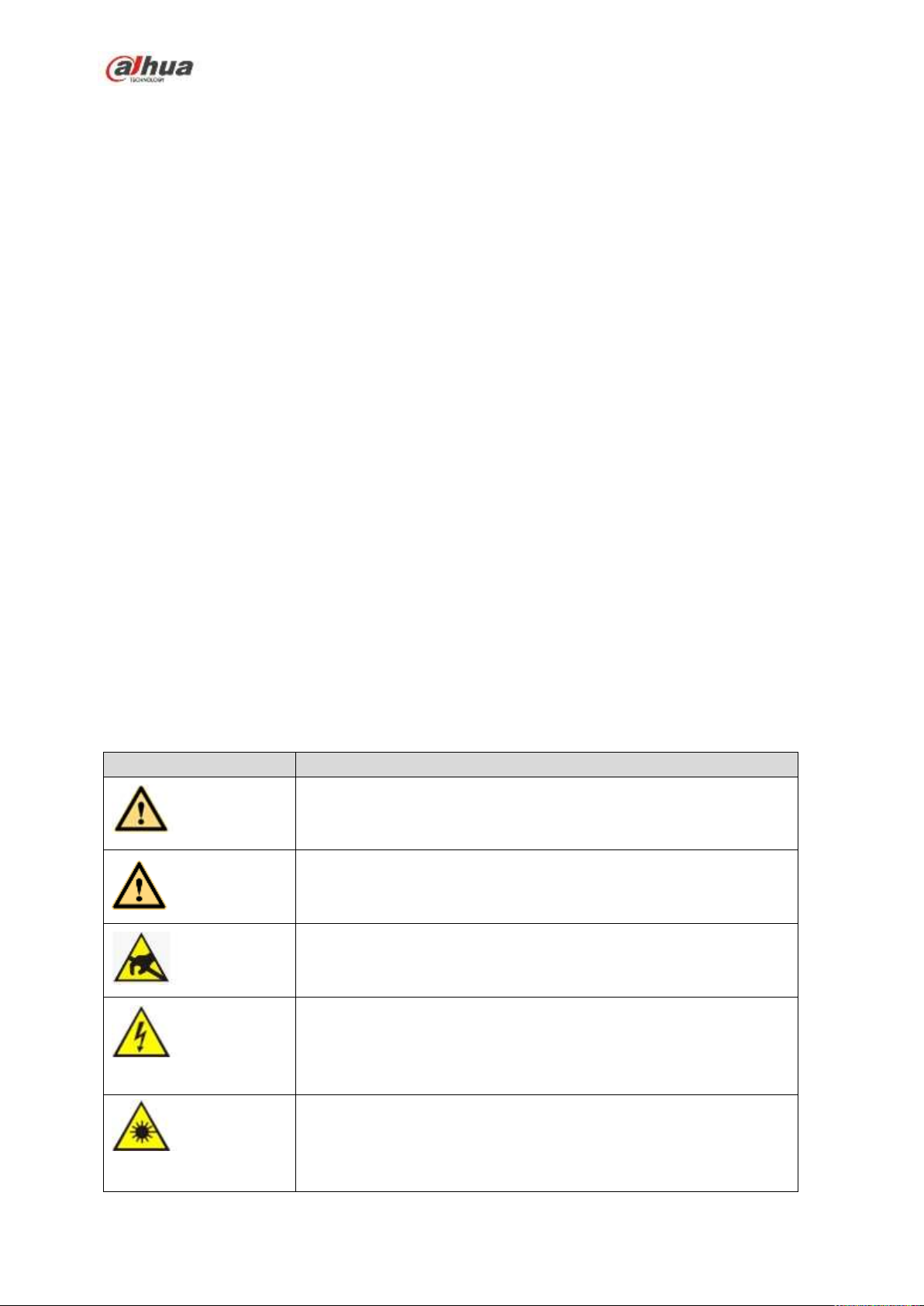
Icon
Note
DANGER
Indicates a hazard with a high level of risk, which if not avoided, will
result in death or serious injury.
WARNING
Indicates a potentially hazardous situation, which if not avoided,
could result in device damage, data loss, performance degradation,
or unexpected results.
Anti-static
Indicates it is the static sensitive device.
Eletric shock
risk
Indicates presence of dangerous high voltage. There is a risk of
electric shock to persons.
High power
laser radiation risk
Indicates presence of high power laser radiation.
NOTE: This equipment has been tested and found to comply with the limits for a Class B digital
device, pursuant to Part 15 of the FCC Rules. These limits are designed to provide reasonable
protection against harmful interference in a residential installation.
This equipment generates, uses and can radiate radio frequency energy and, if not installed and
used in accordance with the instructions, may cause harmful interference to radio
communications.
However, there is no guarantee that interference will not occur in a particular installation. If this
equipment does cause harmful interference to radio or television reception, which can be
determined by turning the equipment off and on, the user is encouraged to try to correct the
interference by one or more of the following measures:
-- Reorient or relocate the receiving antenna.
-- Increase the separation between the equipment and receiver.
--Connect the equipment into an outlet on a circuit different from that to which the receiver is
connected.
-- Consult the dealer or an experienced radio/TV technician for help.
RF exposure warning
This equipment must be installed and operated in accordance with provided instructions and the
antenna(s) used for this transmitter must be installed to provide a separation distance of at least
20 cm from all persons and must not be co-located or operating in conjunction with any other
antenna or transmitter. End-users and installers must be provided with antenna installation
instructions and transmitter operating conditions for satisfying RF exposure compliance.
IEEE 802.11b, 802.11g or 802.11n (20MHz) operation of this product in the U.S.A. is
firmware-limited to channels 1 through 11. IEEE 802.11n (40MHz) operation of this product in the
U.S.A. is firmware-limited to channels 3 through 9.
Safety Instruction
viii
Page 10

Icon
Note
Tips
It is intended to help you to fix a problem or save your time.
Note
Provides additional information to emphasize or supplement
important points of the main text.
ix
Page 11

Welcome
Thank you for purchasing our network video recorder!
This user’s manual is designed to be a reference tool for your system.
Please open the accessory bag to check. Contact your local retailer ASAP if something is missing or
damaged in the bag.
Important Safeguards and Warnings
1.Electrical safety
All installation and operation here should conform to your local electrical safety codes.
An apparatus with CLASS I construction shall be connected to a MAINS socket outlet with a
protective earthing connection.
Use a power supply which meets the requirements for SELV (Safety Extra Low Voltage) and
complies with Limited Power Source according to IEC 60950-1. Refer to the device label for detailed
information.
The product must be grounded to reduce the risk of electric shock.
We assume no liability or responsibility for all the fires or electric shock caused by improper handling
or installation.
2.Transportation security
Heavy stress, violent vibration or water splash are not allowed during transportation, storage and
installation.
3.Installation
Keep upwards. Handle with care.
Do not apply power to the NVR before completing installation.
Do not place objects on the NVR.
4.Qualified engineers needed
All the examination and repair work should be done by the qualified service engineers.
We are not liable for any problems caused by unauthorized modifications or attempted repair.
5.Environment
The NVR should be installed in a cool, dry place away from direct sunlight, inflammable, explosive
substances and etc.
This series product shall be transported, storage and used in the specified environments.
Environment which needs to comply with the following conditions:
The function of the ITE being investigated to IEC 60950-1 is considered not likely to require
connection to an Ethernet network with outside plant routing, including campus environment.
The installation instructions clearly state that the ITE is to be connected only to PoE networks without
routing to the outside plant.
6. Accessories
Be sure to use all the accessories recommended by manufacturer.
1
Page 12

Before installation, please open the package and check all the components are included.
Contact your local retailer ASAP if something is broken in your package.
7. Lithium battery
Improper battery use may result in fire, explosion, or personal injury!
When replace the battery, please make sure you are using the same model!
CAUTION
RISK OF EXPLOSION IF BATTERY IS REPLACED BY AN INCORRECT TYPE.
DISPOSE OF USED BATTERIES ACCORDING TO THE INSTRUCTIONS.
2
Page 13

Real-time
Surveillance
VGA, HDMI port. Connect to monitor to realize real-time surveillance.
Some series support TV/VGA/HDMI output at the same time.
Short-cut menu when preview.
Support popular PTZ decoder control protocols. Support preset, tour
and pattern.
Playback
Support each channel real-time record independently, and at the same
time it can support search, forward play, network monitor, record search,
download and etc.
Support various playback modes: slow play, fast play, backward play
and frame by frame play.
Support time title overlay so that you can view event accurate occurred
time
Support specified zone enlargement.
User
Management
Each group has different management powers that can be edited freely.
Every user belongs to an exclusive group.
Storage
Via corresponding setup (such as alarm setup and schedule setup), you
can backup related audio/video data in the network video recorder.
Support Web record and record local video and storage the file in the
client end.
Alarm
Respond to external alarm simultaneously (within 200MS), based on
user’s pre-defined relay setup, system can process the alarm input
correctly and prompt user by screen and voice (support pre-recorded
audio).
Support central alarm server setup, so that alarm information can
remotely notify user automatically. Alarm input can be derived from
various connected peripheral devices.
Alert you via email/sms.
1 Features and Specifications
1.1 Overview
This series NVR is a high performance network video recorder. This series product support local preview,
multiple-window display, recorded file local storage, remote control and mouse shortcut menu operation,
and remote management and control function.
This series product supports center storage, front-end storage and client-end storage. The monitor zone
in the front-end can be set in anywhere. Working with other front-end devices such as IPC, NVS, this
series product can establish a strong surveillance network via the CMS. In the network system, there is
only one network cable from the monitor center to the monitor zone in the whole network. There is no
audio/video cable from the monitor center to the monitor zone. The whole project is featuring of simple
connection, low-cost, low maintenance work.
This series NVR can be widely used in many areas such as public security, water conservancy,
transportation and education.
1.2 Features
3
Page 14

Network
Monitor
Through network, sending audio/video data compressed by IPC or NVS
to client-ends, then the data will be decompressed and display.
Support max 128 connections at the same time.
Transmit audio/video data by HTTP, TCP, UDP, MULTICAST,
RTP/RTCP and etc.
Transmit some alarm data or alarm info by SNMP.
Support WEB access in WAN/LAN.
Window Split
Adopt the video compression and digital process to show several
windows in one monitor. Support 1/4/8/9/16/ 25/36-window display when
preview and 1/4/9/16-window display when playback.
Record
Support normal/motion detect/alarm record function. Save the recorded
files in the HDD, USB device, client-end PC, or network storage server.
You can search or playback the saved files at the local-end or via the
Web/USB device.
Backup
Support network backup, USB2.0 record backup function, the recorded
files can be saved in network storage server, peripheral USB2.0
device, burner and etc.
Network
Management
Supervise NVR configuration and control power via Ethernet.
Support management via WEB.
Peripheral
Equipment
Management
Support peripheral equipment management such as protocol setup and
port connection.
Support transparent data transmission such as RS232 (RS-422), RS485
(RS-485).
Auxiliary
Support switch between NTSC and PAL.
Support real-time system resources information and running statistics
display.
Support log file.
Local GUI output. Shortcut menu operation via mouse.
IR control function (For some series product only.). Shortcut menu
operation via remote control.
Support IPC or NVS remote video preview and control.
Model
100 Series
100-P Series
System
System
Resources
4/8-ch series product support 4/8 HD connection respectively. Total
bandwidth supports 28/56Mbps respectively.
OS
Embedded Linux real-time operation system
Operation
Interface
WEB/Local GUI
Decode
Video Decode
H.264/MJPEG
1.3 Specifications
1.3.1 NVR100/100-P Series
4
Page 15

Model
100 Series
100-P Series
Type
Decode
Capability
Max 2-ch 1080P 30fps or 4-ch 720P 30fps or 8-ch D1 30fps
Video
Video Input
4/8-ch network compression video input
Video Output
1-channel VGA analog video output
HDMI
1-ch HDMI output. Version number is 1.4
Window Split
1/4/8-window
Audio
Audio Input
N/A
Audio Output
N/A
Audio
Compression
Standard
G.711a
Alarm
Alarm Input
N/A
Alarm Output
N/A
Funciton
Storage
1 built-in 2.5-inch SATA port
Multiple-Chann
el Playback
Max 8-channel D1 or 4-channel 720P or 2-channel 1080P playback
Port and
Indicator
RS232 Port
N/A
RS485 Port
N/A
USB Port
2 peripheral USB2.0 ports.
5
Page 16

Model
100 Series
100-P Series
Network
Connection
1 RJ45 10/100Mbps self-adaptive Ethernet port.
PoE
N/A
4
Power Port
1 power socket. Power adapter
power supplying mode. DC 5V
2A power.
1 power socket. Power adapter
power supplying mode. DC 48V
1.25A power.
Power Button
N/A
Power On-off
Button
N/A
IR Receiver
Window
N/A
Clock
Built-in clock.
Indicator Light
N/A
General
Power
Consumption
<10W (No HDD)
Working
Temperature
﹣10℃~﹢55℃
Working
Humidity
10℅~90℅
Air pressure
86kPa~106kPa
Dimension
191.8mm×128.2mm×35.8mm
Weight
0.32kg~0.36kg (No HDD)
Installation
Mode
Desk installation
Model
11 Series
11-P Series
1.3.2 NVR11/11-P Series
6
Page 17

Model
11 Series
11-P Series
System
System
Resources
4/8-ch series product support 4/8 HD connection respectively. Total
bandwidth supports 28/56Mbps respectively.
OS
Embedded Linux real-time operation system
Operation
Interface
WEB/Local GUI
Decode
Video Decode
Type
H.264/MJPEG
Decode
Capability
Max 2-ch 1080P 30fps or 4-ch 720P 30fps or 8-ch D1 30fps
Video
Video Input
4/8-ch network compression video input
Video Output
1-channel VGA analog video output
HDMI
1-ch HDMI output. Version number is 1.4
Window Split
1/4/8-window
Audio
Audio Input
1-ch bidirectional talk input
Audio Output
1-ch bidirectional talk output
Audio
Compression
Standard
G.711a
Alarm
Alarm Input
N/A
Alarm Output
N/A
Funciton
Storage
1 built-in SATA port
7
Page 18

Model
11 Series
11-P Series
Multiple-Chann
el Playback
Max 8-channel D1 or 4-channel 720P or 2-channel 1080P playback
Port and
Indicator
RS232 Port
N/A
RS485 Port
N/A
USB Port
2 peripheral USB2.0 ports.
Network
Connection
1 RJ45 10/100Mbps self-adaptive Ethernet port.
PoE
N/A
4
Power Port
1 power socket. Power adapter
power supplying mode. DC 12V
power.
1 power socket. Power adapter
power supplying mode. DC 48V
power.
Power Button
N/A
Power On-off
Button
N/A
IR Receiver
Window
N/A
Clock
Built-in clock.
Indicator Light
One power status indicator light.
One network status indicator light.
One HDD status indicator light.
General
Power
Consumption
<10W (No HDD)
Working
Temperature
﹣10℃~﹢55℃
Working
Humidity
10℅~90℅
Air pressure
86kPa~106kPa
8
Page 19

Model
11 Series
11-P Series
Dimension
205mm×206.75mm×45.2mm
Weight
0.5kg~1kg (No HDD)
Installation
Mode
Desk installation
Model
21-S2 Series
21-P-S2 Series
21-8P-S2 Series
System
System
Resources
4/8/16-ch series
product support
4/8/16 HD
connection
respectively. Total
bandwidth supports
80Mbps.
4/8-ch series product support 4/8 HD
connection respectively. Total bandwidth
supports 80Mbps.
OS
Embedded Linux real-time operation system
Operation
Interface
WEB/Local GUI
Decode
Video Decode
Type
H.264
Decode
Capability
Max 4-ch 1080P 30fps or 8-ch 720P 30fps or 8-ch D1 30fps
Video
Video Input
4/8/16-ch network
compression video
input
4/8-ch network compression video input
Video Output
1-channel VGA analog video output
HDMI
1-ch HDMI output. Version number is 1.4
Window Split
1/4/8/9/16-window
1/4/8/9-window
1.3.3 NVR21-S2/NVR21-P-S2/NVR21-8P-S2 Series
9
Page 20

Model
21-S2 Series
21-P-S2 Series
21-8P-S2 Series
Audio
Audio Input
1-ch bidirectional talk input
Audio Output
1-ch bidirectional talk output
Audio
Compression
Standard
G.711a
Alarm
Alarm Input
N/A
Alarm Output
N/A
Funciton
Storage
1 built-in SATA port
Multiple-Chann
el Playback
Max 8-channel D1 or 8-channel 720P or 4-channel 1080P playback
Port and
Indicator
RS232 Port
N/A
RS485 Port
N/A
USB Port
2 peripheral USB2.0 ports.
Network
Connection
1 RJ45 10/100Mbps self-adaptive Ethernet port.
PoE
N/A
4
8
Power Port
1 power socket.
Power adapter
power supplying
mode. DC 12V
power.
1 power socket.
Power adapter
power supplying
mode. DC 48V
power.
1 power socket.
Power adapter
power supplying
mode. DC 48V
power.
Power Button
N/A
10
Page 21

Model
21-S2 Series
21-P-S2 Series
21-8P-S2 Series
Power On-off
Button
N/A
IR Receiver
Window
N/A
Clock
Built-in clock.
Indicator Light
One power status indicator light.
One network status indicator light.
One HDD status indicator light.
General
Power
Consumption
<10W (No HDD)
Working
Temperature
﹣10℃~﹢55℃
Working
Humidity
10℅~90℅
Air pressure
86kPa~106kPa
Dimension
205mm×206.75mm×
45.2mm
205mm×206.75mm×
45.2mm
425mm×95mm×260
mm
Weight
0.5kg~2kg (No HDD)
Installation
Mode
Desk installation
Model
11H Series
11H-P Series
System
System
Resources
4/8-ch series product support 4/8 HD connection respectively. Total
bandwidth supports 28/56Mbps respectively.
OS
Embedded Linux real-time operation system
Operation
Interface
WEB/Local GUI
1.3.4 NVR11H/11H-P Series
11
Page 22

Model
11H Series
11H-P Series
Decode
Video Decode
Type
H.264/MJPEG
Decode
Capability
Max 2-ch 1080P 30fps or 4-ch 720P 30fps or 8-ch D1 30fps
Video
Video Input
4/8-ch network compression video input
Video Output
1-channel VGA analog video output
HDMI
1-ch HDMI output. Version number is 1.4
Window Split
1/4/8-window
Audio
Audio Input
1-ch bidirectional talk input
Audio Output
1-ch bidirectional talk output
Audio
Compression
Standard
G.711a
Alarm
Alarm Input
N/A
Alarm Output
N/A
Funciton
Storage
1 built-in SATA port
Multiple-Chann
el Playback
Max 8-channel D1 or 4-channel 720P or 2-channel 1080P playback
Port and
Indicator
RS232 Port
N/A
RS485 Port
N/A
12
Page 23

Model
11H Series
11H-P Series
USB Port
2 peripheral USB2.0 ports.
Network
Connection
1 RJ45 10/100Mbps self-adaptive Ethernet port.
PoE
N/A
4
Power Port
1 power socket. Power adapter
power supplying mode. DC 12V
power.
1 power socket. Power adapter
power supplying mode. DC 48V
power.
Power Button
N/A
Power On-off
Button
N/A
IR Receiver
Window
N/A
Clock
Built-in clock.
Indicator Light
One power status indicator light.
One network status indicator light.
One HDD status indicator light.
General
Power
Consumption
<10W (No HDD)
Working
Temperature
﹣10℃~﹢55℃
Working
Humidity
10℅~90℅
Air pressure
86kPa~106kPa
Dimension
325mm×250.58mm×51mm
Weight
0.5kg~1kg (No HDD)
Installation
Mode
Desk installation
13
Page 24

Model
11HS Series
System
System
Resources
4/8-ch series product support 4/8 HD connection respectively. Total
bandwidth supports 25/56Mbps respectively.
OS
Embedded Linux real-time operation system
Operation
Interface
WEB/Local GUI
Decode
Video Decode
Type
H.264
Decode
Capability
For 8-channel series product: Max 2-ch 1080P 30fps or 4-ch
720P 30fs or 8-ch D1 30fps.
For 4-channel series product: Max 1-ch 1080P 30fps or 4-ch
720P 30fs or 4-ch D1 30fps.
Video
Video Input
4/8-ch network compression video input
Video Output
1-channel VGA analog video output
HDMI
1-ch HDMI output. Version number is 1.4
Window Split
1/4/8-window
Audio
Audio Input
N/A
Audio Output
N/A
Audio
Compression
Standard
G.711a
Alarm
Alarm Input
N/A
Alarm Output
N/A
Funciton
Storage
1 built-in SATA port
Multiple-Chann
el Playback
For 8-channel series product: Max 2-ch 1080P 30fps or 4-ch
720P 30fs or 8-channel D1 30fs playback.
For 4-channel series product: Max 1-ch 1080P 30fps or 4-ch
720P 30fs or 4-ch D1 30fs playback.
Port and
Indicator
RS232 Port
N/A
RS485 Port
N/A
USB Port
2 peripheral USB2.0 ports. One at the front panel and one at the rear
panel.
1.3.5 NVR11HS Series
14
Page 25

Model
11HS Series
Network
Connection
1 RJ45 10/100Mbps self-adaptive Ethernet port.
PoE Port
N/A
Power Port
1 power socket. Power adapter power supplying mode. DC 12V/1.5A
power.
Power Button
N/A
Power On-off
Button
N/A
IR Receiver
Window
N/A
Clock
Built-in clock.
Indicator Light
One power status indicator light.
One network status indicator light.
One HDD status indicator light.
General
Power
Consumption
<10W (No HDD)
Working
Temperature
﹣10℃~﹢55℃
Working
Humidity
10℅~90℅
Air pressure
86kPa~106kPa
Dimension(W*
D*H)
260mm×220mm×44mm
Weight
0.7kg~0.8kg (No HDD)
Installation
Mode
Desk installation
Model
NVR21HS-S2
Series
NVR21HS-P-S2
Series
NVR21HS-8P-S2
Series
System
System
Resources
4/8/16-ch series
product support
4/8/16 HD
connection
respectively. Total
bandwidth supports
80Mbps.
4/8-ch series product support 4/8 HD
connection respectively. Total bandwidth
supports 80Mbps.
OS
Embedded Linux real-time operation system
Operation
WEB/Local GUI
1.3.6 NVR21HS-S2/21HS-P-S2/21HS-8P-S2 Series
15
Page 26

Model
NVR21HS-S2
Series
NVR21HS-P-S2
Series
NVR21HS-8P-S2
Series
Interface
Decode
Video Decode
Type
H.264
Decode
Capability
Max 4-ch 1080P 30fps or 8-ch 720P 30fs or 8-ch D1 30fps
Video
Video Input
4/8/16-ch network
compression video
input
4/8-ch network compression video input
Video Output
1-channel VGA analog video output
HDMI
1-ch HDMI output. Version number is 1.4
Window Split
1/4/8/9/16-window
1/4/8/9-window
Audio
Audio Input
1-ch bidirectional talk input
Audio Output
1-ch bidirectional talk output
Audio
Compression
Standard
G.711a
Alarm
Alarm Input
N/A
Alarm Output
N/A
Funciton
Storage
1 built-in SATA port
Multiple-Chann
el Playback
Max 4-channel 1080P or 8-channel 720P or 8-channel D1 playback
Port and
Indicator
RS232 Port
N/A
RS485 Port
N/A
USB Port
2 peripheral USB2.0 ports.
Network
Connection
1 RJ45 10/100Mbps self-adaptive Ethernet port.
PoE Port
N/A
4
8
Power Port
1 power socket.
Power adapter
power supplying
mode. DC 12V
power.
1 power socket.
Power adapter
power supplying
mode. DC 48V
power.
1 power socket.
Power adapter
power supplying
mode. DC 48V
power.
16
Page 27

Model
NVR21HS-S2
Series
NVR21HS-P-S2
Series
NVR21HS-8P-S2
Series
Power Button
N/A
Power On-off
Button
N/A
IR Receiver
Window
N/A
Clock
Built-in clock.
Indicator Light
One power status indicator light.
One network status indicator light.
One HDD status indicator light.
General
Power
Consumption
<10W (No HDD)
Working
Temperature
﹣10℃~﹢55℃
Working
Humidity
10℅~90℅
Air pressure
86kPa~106kPa
Dimension(W×
D×H)
260mm×220mm×44mm
Weight
0.7kg~0.8kg (No HDD)
Installation
Mode
Desk installation
Model
41HS-W-S2 Series
System
System
Resources
4/8-ch series product support 4/8 HD connection respectively. Total
bandwidth supports 80Mbps.
OS
Embedded Linux real-time operation system
Operation
Interface
WEB/Local GUI
Decode
Video Decode
Type
H.264/MJPEG/MPEG4
Decode
Capability
Max 8-ch 1080P or 4-ch 3M or 2-ch 5M.
Video
Video Input
4/8-ch network compression video input
Video Output
1-channel VGA analog video output
HDMI
1-ch HDMI output. Version number is 1.4
1.3.7 NVR41HS-W-S2 Series
17
Page 28

Model
41HS-W-S2 Series
Window Split
1/4/8/9-window
Audio
Audio Input
N/A
Audio Output
N/A
Audio
Compression
Standard
G.711a
Alarm
Alarm Input
N/A
Alarm Output
N/A
Funciton
Storage
1 built-in SATA port
Multiple-Chann
el Playback
Max 8-ch 1080P playback
Port and
Indicator
RS232 Port
N/A
RS485 Port
N/A
USB Port
2 peripheral USB2.0 ports. One at the front panel and one at the rear
panel.
Network
Connection
1 RJ45 10/100Mbps self-adaptive Ethernet port.
PoE Port
N/A
Power Port
1 power socket. Power adapter power supplying mode. DC 12V/2A
power.
Power Button
N/A
Power On-off
Button
N/A
IR Receiver
Window
N/A
Clock
Built-in clock.
Indicator Light
One power status indicator light.
One network status indicator light.
One HDD status indicator light.
General
Power
Consumption
<30W (No HDD)
Working
Temperature
﹣10℃~﹢55℃
Working
Humidity
10℅~90℅
Air pressure
86kPa~106kPa
18
Page 29

Model
41HS-W-S2 Series
Dimension(W*
D*H)
375mm×287mm×52mm
Weight
1.5kg~2.5kg(No HDD)
Installation
Mode
Desk installation
Model
41 Series
41-P Series
41-8P Series
41-W Series
System
System
Resources
4/8/16-ch series product support 4/8/16 HD connection respectively.
Total bandwidth supports 28/56/80Mbps respectively.
OS
Embedded Linux real-time operation system
Operation
Interface
WEB/Local GUI
Decode
Video Decode
Type
H.264/MJPEG/MJPEG4
Decode
Capability
Max 2-ch 5M 25fps or 4-ch 3M 25fps or 4-ch 1080P 30fps
or 8-ch 720P 30fs
Video
Video Input
4/8/16-ch network compression video input
Video Output
1-channel VGA analog video output
HDMI
1-ch HDMI output. Version number is 1.4
Window Split
1/4/8/9/16-window
1/4-window
Audio
Audio Input
1-ch bidirectional talk input
Audio Output
1-ch bidirectional talk output
Audio
Compression
Standard
G.711a
Alarm
Alarm Input
N/A
Alarm Output
N/A
Funciton
Storage
1 built-in SATA port
Multiple-Chann
el Playback
Max 4-channel 1080P playback
WIFI AP
N/A
Yes
Port and
RS232 Port
N/A
1.3.8 NVR41/41-P/41-8P/41-W Series
19
Page 30

Model
41 Series
41-P Series
41-8P Series
41-W Series
Indicator
RS485 Port
N/A
USB Port
2 peripheral USB2.0 ports.
Network
Connection
1 RJ45 10/100Mbps self-adaptive Ethernet port.
PoE Port
N/A
4 8 N/A
Power Port
1 power
socket. Power
adapter power
supplying
mode. DC 12V
power.
1 power socket. Power adapter
power supplying mode. DC 48V
power.
1 power
socket. Power
adapter power
supplying
mode. DC 12V
power.
Power Button
1 button
Power On-off
Button
N/A
IR Receiver
Window
N/A
Clock
Built-in clock.
Indicator Light
One power status indicator light.
One network status indicator light.
One HDD status indicator light.
General
Power
Consumption
<10W (No HDD)
Working
Temperature
﹣10℃~﹢55℃
Working
Humidity
10℅~90℅
Air pressure
86kPa~106kPa
Dimension
205mm×206.75mm×45.2mm
270mm×204m
m×42mm
205mm×206.7
5mm×45.2mm
Weight
0.5kg~1kg (No HDD)
Installation
Mode
Desk installation
Model
41H Series
41H-P Series
41H-8P Series
System
System
Resources
4/8/16-ch series product support 4/8/16 HD connection respectively.
Total bandwidth supports 28/56/80Mbps respectively.
OS
Embedded Linux real-time operation system
1.3.9 NVR41H/41H-P/41H-8P Series
20
Page 31

Model
41H Series
41H-P Series
41H-8P Series
Operation
Interface
WEB/Local GUI
Decode
Video Decode
Type
H.264/MJPEG/MJPEG4
Decode
Capability
Max 2-ch 5M 25fps or 4-ch 3M 25fps or 4-ch 1080P 30fps
or 8-ch 720P 30fs
Video
Video Input
4/8/16-ch network compression video input
Video Output
1-channel VGA analog video output
HDMI
1-ch HDMI output. Version number is 1.4
Window Split
1/4/8/9/16-window
Audio
Audio Input
1-ch bidirectional talk input
Audio Output
1-ch bidirectional talk output
Audio
Compression
Standard
G.711a
Alarm
Alarm Input
N/A
2-channel
Alarm Output
N/A
2-channel
Funciton
Storage
1 built-in SATA port
Multiple-Chann
el Playback
Max 4-channel 1080P playback
Port and
Indicator
RS232 Port
N/A
RS485 Port
N/A
USB Port
2 peripheral USB2.0 ports.
Network
Connection
1 RJ45 10/100Mbps self-adaptive Ethernet port.
PoE Port
N/A
4
8
Power Port
1 power socket.
Power adapter
power supplying
mode. DC 12V
power.
1 power socket. Power adapter power
supplying mode. DC 48V power.
Power Button
1 button
Power On-off
N/A
21
Page 32

Model
41H Series
41H-P Series
41H-8P Series
Button
IR Receiver
Window
N/A
Clock
Built-in clock.
Indicator Light
One power status indicator light.
One network status indicator light.
One HDD status indicator light.
General
Power
Consumption
<10W (No HDD)
Working
Temperature
﹣10℃~﹢55℃
Working
Humidity
10℅~90℅
Air pressure
86kPa~106kPa
Dimension
325mm×250.58mm×51mm
Weight
0.5kg~1kg (No HDD)
Installation
Mode
Desk installation
Model
NVR22-S2 Series
NVR22-P-S2 Series
NVR22-8P-S2
Series
System
System
Resources
4/8/16-ch series
product support
4/8/16 HD
connection
respectively. Total
bandwidth supports
80Mbps.
4/8-ch series product support 4/8 HD
connection respectively. Total bandwidth
supports 80Mbps.
OS
Embedded Linux real-time operation system
Operation
Interface
WEB/Local GUI
Decode
Video Decode
Type
H.264
Decode
Capability
Max 4-ch 1080P 30fps or 8-ch 720P 30fs or 8-ch D1 30fps
Video
Video Input
4/8/16-ch network
compression video
input
4/8-ch network compression video input
1.3.10 NVR22-S2/22-P-S2/22-8P-S2 Series
22
Page 33

Model
NVR22-S2 Series
NVR22-P-S2 Series
NVR22-8P-S2
Series
Video Output
1-channel VGA analog video output
HDMI
1-ch HDMI output. Version number is 1.4
Window Split
1/4/8/9/16-window
1/4/8/9-window
Audio
Audio Input
1-ch bidirectional talk input
Audio Output
1-ch bidirectional talk output
Audio
Compression
Standard
G.711a
Alarm
Alarm Input
N/A
Alarm Output
N/A
Funciton
Storage
2 built-in SATA ports
Multiple-Chann
el Playback
Max 4-channel 1080P or 8-channel 720P or 8-channel D1 playback
Port and
Indicator
RS232 Port
N/A
RS485 Port
N/A
USB Port
2 peripheral USB2.0 ports.
Network
Connection
1 RJ45 10/100Mbps self-adaptive Ethernet port.
PoE Port
N/A
4
8
Power Port
1 power socket.
Power adapter
power supplying
mode. DC 12V
power.
1 power socket.
Power adapter
power supplying
mode. DC 48V
power.
1 power socket.
Power adapter
power supplying
mode. DC 48V
power.
Power Button
N/A
Power On-off
Button
N/A
IR Receiver
Window
N/A
Clock
Built-in clock.
Indicator Light
One power status indicator light.
One network status indicator light.
23
Page 34

Model
NVR22-S2 Series
NVR22-P-S2 Series
NVR22-8P-S2
Series
One HDD status indicator light.
General
Power
Consumption
<10W (No HDD)
Working
Temperature
﹣10℃~﹢55℃
Working
Humidity
10℅~90℅
Air pressure
86kPa~106kPa
Dimension(W×
D×H)
375mm×287mm×52mm
Weight
1.5kg~2.5kg (No HDD)
Installation
Mode
Desk installation
Model
42N Series
System
System
Resource
s
4/8/16/32-channel series product support 4/8/16/32-channel HD connection
respectively. Main stream bandwidth supports 40/80/160/160Mbps
respectively.
Operation
System
Embedded Linux real-time operation system
Operation
Interface
WEB/Local GUI
Decode
Video
Compres
sion
H.264/MJPEG/MPEG4
Decode
Capacity
Max supports 16-channel D1, or 8-channel 720P, or 4-channel 1080P, or
4*3M or 2*5M decode.
Video
Video
Input
4/8/16/32-ch network compression video input
Video
Output
1-channel VGA analog video output.
HDMI
1-ch HDMI output. Version number is 1.4
Window
Split
1/4/8/9/16-window
Audio
Audio
Input
1-ch bidirectional talk input
Audio
Output
1-ch bidirectional talk output
1.3.11 NVR42N Series
24
Page 35

Audio
Compres
sion
G.711a
Alarm
Alarm
Input
N/A
Alarm
Output
N/A
Function
Storage
2 built-in SATA ports.
Multiple-c
hannel
Playback
Max 8-channel 720P/4-channel 1080P playback at the same time.
Port and
Indicator
RS232
Port
One RS232 port to debug transparent COM data.
RS485
port
One RS485 port to control PTZ. Support various protocols.
USB2.0
Port
Three peripheral USB2.0 ports.
Network
Connecti
on
1 RJ45 10/100/1000Mbps self-adaptive Ethernet port.
Power
Port
One power port, power adapter. Input DC 12V.
Power
Button
One button. At the rear panel.
Power
On-off
Button
One button. At the front-panel.
IR
Receiver
Window
Support IR remote control
Clock
Built-in clock.
Indicator
Light
One power status indicator light.
One network status indicator light.
One HDD status indicator light.
General
Power
Consump
tion
<30W(No HDD)
Working
Temperat
ure
-10℃~+55℃
Working
Humidity
10℅-90℅
Air
86kpa-106kpa
25
Page 36

pressure
Dimensio
n
375mm×287mm×52mm
Weight
1.5kg~2.5kg(No HDD)
Installatio
n
Desk installation
Model
42 Series
42-P Series
42-8P Series
System
System
Resource
s
4/8/16/32-channel series product support 4/8/16/32-channel HD connection
respectively. Main stream bandwidth supports 40/80/160/160Mbps
respectively.
Operation
System
Embedded Linux real-time operation system
Operation
Interface
WEB/Local GUI
Decode
Video
Compres
sion
H.264/MJPEG/MPEG4
Decode
Capacity
Max supports 16-channel D1, or 8-channel 720P, or 4-channel 1080P, or
4*3M or 2*5M decode.
Video
Video
Input
4/8/16/32-ch network compression video input
Video
Output
1-channel VGA analog video output.
HDMI
1-ch HDMI output. Version number is 1.4
Window
Split
1/4/8/9/16-window
Audio
Audio
Input
1-ch bidirectional talk input
Audio
Output
1-ch bidirectional talk output
Audio
Compres
sion
G.711a
Alarm
Alarm
Input
4-ch alarm input
Alarm
Output
2-ch alarm output
Function
Storage
2 built-in SATA ports.
Multiple-c
hannel
Max 8-channel 720P/4-channel 1080P playback at the same time.
1.3.12 NVR42/42-P/42-8P Series
26
Page 37

Playback
Port and
Indicator
RS232
Port
One RS232 port to debug transparent COM data.
RS485
port
One RS485 port to control PTZ. Support various protocols.
USB2.0
Port
Three peripheral USB2.0 ports.
Network
Connecti
on
1 RJ45 10/100/1000Mbps self-adaptive Ethernet port.
Power
Port
One power port,
power adapter. Input
DC 12V.
Two power ports. Input
DC 12V/DC 48V.
One power ports.
Input 100-240V ,
47~63Hz.
Power
Button
One button. At the rear panel.
Power
On-off
Button
One button. At the front-panel.
IR
Receiver
Window
Support IR remote control
Clock
Built-in clock.
Indicator
Light
One power status indicator light.
One network status indicator light.
One HDD status indicator light.
General
Power
Consump
tion
<30W(No HDD)
Working
Temperat
ure
-10℃~+55℃
Working
Humidity
10℅-90℅
Air
pressure
86kpa-106kpa
Dimensio
n
375mm×287mm×52m
m
375mm×287mm×52mm
295mm×275mm×47m
m
Weight
1.5kg~2.5kg(No HDD)
Installatio
n
Desk installation
Model
42-16P Series
1.3.13 NVR42-16P Series
27
Page 38

System
System
Resource
s
16/32-channel series product support 4/8/16/32-channel HD connection
respectively. Main stream/sub stream bandwidth supports 200Mbps.
Operation
System
Embedded Linux real-time operation system
Operation
Interface
WEB/Local GUI
Decode
Video
Compres
sion
H.264/MJPEG/MPEG4
Decode
Capacity
Max supports 32-channel D1, or 16-channel 720P, or 8-channel 1080P, or
4*3M or 2*5M decode.
Video
Video
Input
4/8/16/32-ch network compression video input
Video
Output
1-channel VGA analog video output.
HDMI
1-ch HDMI output. Version number is 1.4
Window
Split
1/4/8/9/16-window
Audio
Audio
Input
1-ch bidirectional talk input
Audio
Output
1-ch bidirectional talk output
Audio
Compres
sion
G.711a
Alarm
Alarm
Input
4-ch alarm input
Alarm
Output
2-ch alarm output
Function
Storage
2 built-in SATA ports.
Multiple-c
hannel
Playback
Max 16-channel 720P/8-channel 1080P playback at the same time.
Port and
Indicator
RS232
Port
One RS232 port to debug transparent COM data.
RS485
port
One RS485 port to control PTZ. Support various protocols.
USB2.0
Port
One peripheral USB2.0 port.
One peripheral USB3.0 port.
Network
Connecti
on
1 RJ45 10/100/1000Mbps self-adaptive Ethernet port.
28
Page 39

Power
Port
One power ports. Input 100-240V,47~63Hz.
Power
Button
One button. At the rear panel.
Power
On-off
Button
N/A
IR
Receiver
Window
N/A
Clock
Built-in clock.
Indicator
Light
One power status indicator light.
One network status indicator light.
One HDD status indicator light.
General
Power
Consump
tion
<30W(No HDD)
Working
Temperat
ure
-10℃~+55℃
Working
Humidity
10℅-90℅
Air
pressure
86kpa-106kpa
Dimensio
n
375mm×287mm×52mm
Weight
1.5kg~2.5kg(No HDD)
Installatio
n
Desk installation
Model
NVR42-4K Series
NVR42-8P-4K Series
System
System
Resource
s
8/16/32-channel series product support 8/16/32-channel HD connection
respectively. The main stream bandwidth supports 48/96/192Mbps.
Operation
System
Embedded Linux real-time operation system
Operation
Interface
WEB/Local GUI
Decode
Video
Compres
sion
H.264/MJPEG/MPEG4
1.3.14 NVR42-4K/42-8P-4K Series
29
Page 40

Decode
Capacity
H.264: Max supports 16-channel D1, or 8-channel 720P, 4-channel 1080P
or 1-channel 4K decode.
H.265: Max supports 16-channel D1, or 8-channel 720P, 4-channel 1080P
or 1-channel 4K decode.
Video
Video
Input
8/16/32-ch network compression video input
Video
Output
1-channel VGA analog video output.
HDMI
1-ch HDMI output. Version number is 1.4
Window
Split
1/4/8/9/16-window
Audio
Audio
Input
1-ch bidirectional talk input
Audio
Output
1-ch bidirectional talk output
Audio
Compres
sion
G.711a, G.711u, PCM, G726
Alarm
Alarm
Input
8-ch alarm input
Alarm
Output
3-ch alarm output
Relay output. Relay (DC 30V /1A,AC 125V/0.5A(Activation output))
Including one controllable DC +12V output.
Function
Storage
2 built-in SATA ports.
Multiple-c
hannel
Playback
Max 8-channel 720P/4-channel 1080P/1-channel 4K playback at the same
time.
Port and
Indicator
RS232
Port
One RS232 port to debug transparent COM data.
RS485
port
One RS485 port to control PTZ. Support various protocols.
USB Port
2 peripheral USB ports: One USB2.0 at the front panel and one USB3.0 at
the rear panel.
Network
Connecti
on
One RJ45 10/100/1000Mbps self-adaptive Ethernet port.
Power
Port
One power socket. Power adapter
power supplying. Input DC 12V
power.
One power port. Input 100-240V,
47~63Hz.
Power
Button
One button. At the rear panel.
Power
On-off
Button
N/A
30
Page 41

IR
Receiver
Window
N/A
Clock
Built-in clock.
General
Indicator
Light
One power status indicator light.
One network status indicator light.
One HDD status indicator light.
One device running status indicator light.
Power
Consump
tion
<20W(No HDD)
Working
Temperat
ure
-10℃~+55℃
Working
Humidity
10℅-90℅
Air
pressure
86kpa-106kpa
Dimensio
n
1U, 375mm(W) × 49.8mm(H) × 250mm(D)
Weight
1.65kg(No HDD)
Installatio
n
Desk/rack installation
Model
NVR52-4KS2/52-8P-4KS2/52-16P-4KS2 Series
System
System
Resource
s
8/16/32/64-channel series product support 8/16/32/64-channel HD
connection respectively. The main stream bandwidth supports
80/160/320/320Mbps.
Operation
System
Embedded Linux real-time operation system
Operation
Interface
WEB/Local GUI
Decode
Video
Compres
sion
MPEG4,MJPEG,H.264,H.265
Decode
Capacity
H.264/H.265: Max supports 64-channel D1, or 32-channel 720P,
16-channel 1080P or 4-channel 4K decode.
Video
Video
Input
8/16/32/64-ch network compression video input
Video
Output
1-channel VGA analog video output.
HDMI
1-ch HDMI output. Version number is 1.4
1.3.15 NVR52-4KS2/52-8P-4KS2/52-16P-4KS2 Series
31
Page 42

Window
Split
1/4/8/9/16/25/36-window
Audio
Audio
Input
1-ch bidirectional talk input
Audio
Output
1-ch bidirectional talk output
Audio
Compres
sion
G.711a, G.711u, PCM, G.726 (The bidirectional talk function supports
G.711a, G.711u, PCM only.)
Alarm
Alarm
Input
4-ch alarm input
Alarm
Output
3-ch relay output
Function
Storage
2 built-in SATA ports.
Multiple-c
hannel
Playback
Max 64-channel D1/32-channel 720P/16-channel 1080P/4-channel 4K
playback at the same time.
Record
Mode
Overwrite
Backup
Mode
Flash disk, DVD burner.
Port and
Indicator
Network
Protocol
IPv4/IPv6/HTTP/UPnP/NTP/SADP/SNMP/PPPoE/DNS/FTP/ONVIF(Versio
n 2.4)/PSIA
RS232
Port
One RS232 port to debug transparent COM data.
RS485
port
One RS485 port to control PTZ. Support various protocols.
USB Port
2 peripheral USB ports: One USB2.0 at the front panel and one USB3.0 at
the rear panel.
Network
Connecti
on
One RJ45 10/100/1000Mbps self-adaptive Ethernet port.
Power
Port
One power socket. Power adapter power supplying. Input DC 12V-4A
power.
Power
Button
One button. At the rear panel.
Power
On-off
Button
N/A
IR
Receiver
Window
N/A
32
Page 43

General
Indicator
Light
One power status indicator light.
One network status indicator light.
One HDD status indicator light.
One device running status indicator light.
Power
DC 12V
Power
Consump
tion
General series: 9.5W(No HDD)
8 PoE series: 14.5W(No HDD)
16 PoE series: 15.2W(No HDD)
Working
Temperat
ure
-10℃~+55℃
Working
Humidity
10℅-90℅
Air
pressure
86kpa-106kpa
Dimensio
n
General series: 375mm(W) × 56mm(H) × 281.4mm(D)
PoE series: 375mm(W) × 53mm(H) × 327.3mm(D)
Weight
(No HDD)
General series: : 1.60Kg
8 PoE series: 2.60Kg
16 PoE series: 2.70Kg
Installatio
n
Desk/rack installation
Model
NVR44 Series
NVR44-8P Series
NVR44-16P Series
System
System
Resource
s
8/16/32-channel series product support 8/16/32-channel HD connection
respectively. The main stream bandwidth supports 200Mbps.
Operation
System
Embedded Linux real-time operation system
Operation
Interface
WEB/Local GUI
Decode
Video
Compres
sion
H.264/MJPEG/MPEG4
Decode
Capacity
Max supports 16-channel D1, or 8-channel 720P, or 4-channel 3M or 2*5M
decode.
Video
Video
Input
8/16/32-ch network compression video input
Video
Output
1-channel VGA analog video output.
HDMI
1-ch HDMI output. Version number is 1.4
Window
1/4/8/9/16-window
1.3.16 NVR44/44-8P/44-16P Series
33
Page 44

Split
Audio
Audio
Input
1-ch bidirectional talk input
Audio
Output
1-ch bidirectional talk output
Audio
Compres
sion
G.711a
Alarm
Alarm
Input
16-ch alarm input
Alarm
Output
4-ch alarm output
Relay output. Relay (DC 30V /1A,AC 125V/0.5A(Activation output))
Including one controllable DC +12V output.
Function
Storage
4 built-in SATA ports. 1 external eSATA port.
Multiple-c
hannel
Playback
Max 8-channel 720P/4-channel 1080P playback at the same time.
Port and
Indicator
RS232
Port
One RS232 port to debug transparent COM data.
RS485
port
One RS485 port to control PTZ. Support various protocols.
USB2.0
Port
2 peripheral USB2.0 ports. One at the front panel and one at the rear panel.
Network
Connecti
on
One RJ45 10/100/1000Mbps self-adaptive Ethernet port.
Power
Port
One power port. Input 100-240V,50~60Hz.
Power
Button
One button. At the rear panel.
Power
On-off
Button
One button. At the front-panel.
IR
Receiver
Window
Support IR remote control
Clock
Built-in clock.
General
Indicator
Light
One power status indicator light.
One network status indicator light.
One HDD status indicator light.
Power
Consump
tion
<30W(No HDD)
34
Page 45

Working
Temperat
ure
-10℃~+55℃
Working
Humidity
10℅-90℅
Air
pressure
86kpa-106kpa
Dimensio
n
1.5U, 440mm × 460mm × 68mm
Weight
5kg~6kg(No HDD)
Installatio
n
Desk installation
Specifications
NVR44-4K
System
Main Processor
Industrial embedded micro processor
Operation System
Embedded LINUX system
System
Resources
Max 8-channel×1080P connection,
User Interface
WEB, local GUI
Audio
Parameters
Audio Input
1-ch MIC bidirectional talk audio input
Audio Output
1-ch MIC bidirectional talk audio output
Audio
Compression
Standard
G.711a, G.711u, PCM, G726
Video
Parameters
Video Input
8/16/32-ch network compression video input
Video Output
1-channel VGA
2-channel HDMI.
Video
Compression
Standard
H.264
Window Split
Mode
The 1st screen: 1/4/8/9/16-screen.
The 2nd screen: 1/4-screen.
Alarm
Parameters
Alarm Input
16-channel
Alarm Output
8-channel relay output
Decode
Parameters
Decode Type
MPEG4,H.264,H.265
Decode Capability
16-channel×D1;8-channel×720P, 4-channel 1080P;1-channel
4K
Functions
Record Mode
Manual recording, motion detection recording, schedule
recording and alarm recording.
Priority: Manual recording>card number recording-> alarm
recording>motion detection recording>schedule recording.
1.3.17 NVR44-4K Series
35
Page 46

Multi-Channel
Playback
Max support 64M(H265&H264 1:1) playback at the same
time.
Motion Detect
Each screen supports 396/330((PAL 22×18, NTSC 22×15)
detection zones. Various sensitivity levels.
Privacy Mask
Each channel supports 4 privacy mask zones.
Record Mode
Overwrite
Backup Mode
Flash disk, eSATA, DVD burner.
Network
Function
Network Protocol
IPv4/IPv6/HTTP/UPnP/NTP/SADP/SNMP/PPPoE/DNS/FTP/ON
VIF/PSIA
SATA Port
4 SATA Ports
eSATA Port
1 eSATA port
RS232 Port
1 RS232 port. To debug and transmit COM data.
RS485 Port
1 RS485 port. To control peripheral PTZ and etc. Support
various protocols.
USB Port
1 USB 2.0 port at the front panel and 2 USB3.0 ports at the
rear panel.
HDMI Port
2 HDMI ports
Network Port
2 RJ45 10/100/1000Mbps self-adaptive Ethernetet ports+2
1000Mbps self-adaptive fiber ports
Power On-off
Button
One at the rear panel.
Indicator Light
4 indicator lights.
1 system running status indicator light
1 HDD indicator light
1 network status indicator light
1 power status indicator light
General
Parameters
Power
AC100~240V
Power
Consumption
General series: <17W(No HDD),
PoE series: <26.5W (No HDD),
Working
Temperature
0℃~50℃
Working Humidity
10%~90%(No condensation)
Dimensions (W×
H×D)
440×76×405mm
Weight
General series:4.35 kg(No HDD),
PoE series: 4.65kg (No HDD),
Installation Mode
Rack/desktop
Specifications
NVR54-4KS2/54-16P-4KS2 Series
System
Main Processor
Industrial embedded micro processor
Operation System
Embedded LINUX system
System
Resources
8/16/32/64-channel main stream connection: max supports
80/160/320/320Mbps
1.3.18 NVR54-4KS2/54-16P-4KS2 Series
36
Page 47

User Interface
WEB, local GUI
Audio
Parameters
Audio Input
1-ch MIC bidirectional talk audio input
Audio Output
1-ch MIC bidirectional talk audio output
Audio
Compression
Standard
G.711a, G.711u, PCM, G.726 (The bidirectional talk supports
G.711a, G.711u, PCM only.)
Video
Parameters
Video Input
8/16/32/64-ch network compression video input
Video Output
1-channel VGA
2-channel HDMI.
Video
Compression
Standard
H.264
Window Split
Mode
1/4/8/9/16/25/36/64-screen.
Alarm
Parameters
Alarm Input
16-channel
Alarm Output
6-channel relay output
Decode
Parameters
Decode Type
MPEG4,MJPEG,H.264,H.265
Decode Capability
H.264/H.265: 64-channel×D1, 32-channel×720P, 16-channel
1080P; 4-channel 4K.
Functions
Record Mode
Manual recording, motion detection recording, schedule
recording and alarm recording.
Priority: Manual recording>card number recording-> alarm
recording>motion detection recording>schedule recording.
Multi-Channel
Playback
Max support 16-channel 1080P playback at the same time.
Motion Detect
Each screen supports 396/330((PAL 22×18, NTSC 22×15)
detection zones. Various sensitivity levels.
Privacy Mask
Each channel supports 4 privacy mask zones.
Record Mode
Overwrite
Backup Mode
Flash disk, eSATA, DVD burner.
Network
Function
Network Protocol
IPv4/IPv6/HTTP/UPnP/NTP/SADP/SNMP/PPPoE/DNS/FTP/
ONVIF(Version 2.4)/PSIA
SATA Port
4 SATA Ports
eSATA Port
1 eSATA port
RS232 Port
1 RS232 port. To debug and transmit COM data.
RS485 Port
1 RS485 port. To control peripheral PTZ and etc. Support
various protocols.
USB Port
1 USB 2.0 port at the front panel and 2 USB3.0 ports at the
rear panel.
HDMI Port
2 HDMI ports
Network Port
2 RJ45 10/100/1000Mbps self-adaptive Ethernet ports
37
Page 48

Power Port
One power socket. Power adapter power supplying. Input AC
100V~240V,50Hz~60Hz.
Power On-off
Button
One at the rear panel.
Indicator Light
4 indicator lights.
1 system running status indicator light
1 HDD indicator light
1 network status indicator light
1 power status indicator light
General
Parameters
Power
AC90~264V
Power
Consumption
General series: 16.7W(No HDD)
16 PoE series: 17.5W(No HDD)
Working
Temperature
-10℃~55℃
Working Humidity
10%~90%(No condensation)
Dimensions (W×
H×D)
440×76×411mm
Weight(No HDD)
General series:4.30Kg,
PoE series: 4.65Kg,
Installation Mode
Rack/desktop
Specifications
NVR48-4K
System
Main Processor
Industrial embedded micro processor
Operation System
Embedded LINUX system
System
Resources
Max 8-channel×1080P connection,
User Interface
WEB, local GUI
Audio
Parameters
Audio Input
1-ch MIC bidirectional talk audio input
Audio Output
1-ch MIC bidirectional talk audio output
Audio
Compression
Standard
G.711a, G.711u, PCM, G726
Video
Parameters
Video Input
8/16/32-ch network compression video input
Video Output
1-channel VGA
2-channel HDMI.
Video
Compression
Standard
H.264
Window Split
Mode
The 1st screen: 1/4/8/9/16-screen.
The 2nd screen: 1/4-screen.
Alarm
Parameters
Alarm Input
16-channel
Alarm Output
6-channel relay output
1.3.19 NVR48-4K Series
38
Page 49

Decode
Parameters
Decode Type
MPEG4,H.264,H.265
Decode Capability
16-channel×D1;8-channel×720P, 4-channel 1080P;1-channel
4K
Functions
Record Mode
Manual recording, motion detection recording, schedule
recording and alarm recording.
Priority: Manual recording>card number recording-> alarm
recording>motion detection recording>schedule recording.
Multi-Channel
Playback
Max support 64M(H265&H264 1:1) playback at the same
time.
Motion Detect
Each screen supports 396/330((PAL 22×18, NTSC 22×15)
detection zones. Various sensitivity levels.
Privacy Mask
Each channel supports 4 privacy mask zones.
Record Mode
Overwrite
Backup Mode
Flash disk, eSATA, DVD burner.
Network
Function
Network Protocol
IPv4/IPv6/HTTP/UPnP/NTP/SADP/SNMP/PPPoE/DNS/FTP/
ONVIF/PSIA
SATA Port
8 SATA Ports
eSATA Port
1 eSATA port
RS232 Port
1 RS232 port. To debug and transmit COM data.
RS485 Port
1 RS485 port. To control peripheral PTZ and etc. Support
various protocols.
USB Port
2 USB 2.0 ports at the front panel and 2 USB3.0 ports at the
rear panel.
HDMI Port
2 HDMI ports
Network Port
2 RJ45 10/100/1000Mbps self-adaptive Ethernetet ports+2
1000Mbps self-adaptive fiber ports
Power On-off
Button
One at the rear panel.
Indicator Light
4 indicator lights.
1 system running status indicator light
1 HDD indicator light
1 network status indicator light
1 power status indicator light
General
Parameters
Power
AC100~240V
Power
Consumption
General series: <18.8W(No HDD),
PoE series: <27.9W (No HDD),
Working
Temperature
0℃~50℃
Working Humidity
10%~90%(No condensation)
Dimensions (W×
H×D)
440×95×445mm
Weight
General series:6.6 kg(No HDD),
PoE series: 6.75kg (No HDD),
Installation Mode
Rack/desktop
39
Page 50

Specifications
NVR58-4KS2/58-16P-4KS2 Series
System
Main Processor
Industrial embedded micro processor
Operation System
Embedded LINUX system
System
Resources
8/16/32/64-channel main stream max supports
80/160/320/320Mbps
User Interface
WEB, local GUI
Audio
Parameters
Audio Input
1-ch MIC bidirectional talk audio input
Audio Output
1-ch MIC bidirectional talk audio output
Audio
Compression
Standard
G.711a, G.711u, PCM, G.726 (The bidirectional talk supports
G.711a, G.711u, PCM only.)
Video
Parameters
Video Input
8/16/32/64-ch network compression video input
Video Output
1-channel VGA
2-channel HDMI.
Video
Compression
Standard
H.264
Window Split
Mode
1/4/8/9/16/25/36/64-screen.
Alarm
Parameters
Alarm Input
16-channel
Alarm Output
6-channel relay output
Decode
Parameters
Decode Type
MPEG4,MJPEG,H.264,H.265
Decode Capability
H.264/H.265: 64-channel×D1;32-channel×720P, 16-channel
1080P;4-channel 4K
Functions
Record Mode
Manual recording, motion detection recording, schedule
recording and alarm recording.
Priority: Manual recording>card number recording-> alarm
recording>motion detection recording>schedule recording.
Multi-Channel
Playback
Max support 16-channel 1080P playback at the same time.
Motion Detect
Each screen supports 396/330((PAL 22×18, NTSC 22×15)
detection zones. Various sensitivity levels.
Privacy Mask
Each channel supports 4 privacy mask zones.
Record Mode
Overwrite
Backup Mode
Flash disk, eSATA, DVD burner.
Network
Function
Network Protocol
IPv4/IPv6/HTTP/UPnP/NTP/SADP/SNMP/PPPoE/DNS/FTP/
ONVIF(Version 2.4)/PSIA
SATA Port
8 SATA Ports
eSATA Port
1 eSATA port
RS232 Port
1 RS232 port. To debug and transmit COM data.
RS485 Port
1 RS485 port. To control peripheral PTZ and etc. Support
various protocols.
1.3.20 NVR58-4KS2/58-16P-4KS2 Series
40
Page 51

USB Port
2 USB 2.0 ports at the front panel and 2 USB3.0 ports at the
rear panel.
HDMI Port
2 HDMI ports
Network Port
2 RJ45 10/100/1000Mbps self-adaptive Ethernet ports
Power Port
One power socket. Power adapter power supplying. Input AC
100V~240V,50Hz~60Hz.
Power On-off
Button
One at the rear panel.
Indicator Light
4 indicator lights.
1 system running status indicator light
1 HDD indicator light
1 network status indicator light
1 power status indicator light
General
Parameters
Power
AC90~264V
Power
Consumption
General series: 16.7W(No HDD)
16 PoE series: 17.5W(No HDD)
Working
Temperature
-10℃~55℃
Working Humidity
10%~90%(No condensation)
Dimensions (W×
H×D)
439.7×95×450.8mm
Weight (No HDD)
General series:6.55Kg,
PoE series: 7Kg.
Installation Mode
Rack/desktop
Model
NVR48 Series
NVR48-16P Series
System
System
Resource
s
8/16/32-channel series product support 8/16/32-channel HD connection
respectively. The main stream bandwidth supports 200Mbps.
Operation
System
Embedded Linux real-time operation system
Operation
Interface
WEB/Local GUI
Decode
Video
Compres
sion
H.264/MJPEG/MPEG4
Decode
Capacity
Max supports 16-channel D1, or 8-channel 720P, or 4-channel 3M or 2*5M
decode.
Video
Video
Input
8/16/32-ch network compression video input
Video
1-channel VGA analog video output.
1.3.21 NVR48/48-16P Series
41
Page 52

Output
HDMI
1-ch HDMI output. Version number is 1.4
Window
Split
1/4/8/9/16-window
Audio
Audio
Input
1-ch bidirectional talk input
Audio
Output
1-ch bidirectional talk output
Audio
Compres
sion
G.711a
Alarm
Alarm
Input
16-ch alarm input
Alarm
Output
4-ch alarm output
Relay output. Relay (DC 30V /1A,AC 125V/0.5A(Activation output))
Including one controllable DC +12V output.
Function
Storage
4 built-in SATA ports. 1 external eSATA port.
Multiple-c
hannel
Playback
Max 8-channel 720P/4-channel 1080P playback at the same time.
Port and
Indicator
RS232
Port
One RS232 port to debug transparent COM data.
RS485
port
One RS485 port to control PTZ. Support various protocols.
USB2.0
Port
3 peripheral USB2.0 ports. Two at the front panel and one at the rear panel.
Network
Connecti
on
Two RJ45 10/100/1000Mbps
self-adaptive Ethernet ports.
One RJ45 10/100/1000Mbps
self-adaptive Ethernet port.
Power
Port
One power port. Input 100-240V,50~60Hz.
Power
Button
One button. At the rear panel.
Power
On-off
Button
One button. At the front-panel.
IR
Receiver
Window
Support IR remote control
Clock
Built-in clock.
42
Page 53

General
Indicator
Light
One power status indicator light.
One network status indicator light.
One HDD status indicator light.
Power
Consump
tion
<30W(No HDD)
Working
Temperat
ure
-10℃~+55℃
Working
Humidity
10℅-90℅
Air
pressure
86kpa-106kpa
Dimensio
n
440mm × 460mm × 89mm
Weight
5.5kg~6.5kg(No HDD)
Installatio
n
Desk installation
Model
NVR72 Series
NVR72-8P Series
System
System
Resource
s
8/16/32/64-channel series product support 8/16/32/64-channel HD
connection respectively. The main stream bandwidth supports
48/96/192/192Mbps.
Operation
System
Embedded Linux real-time operation system
Operation
Interface
WEB/Local GUI
Decode
Video
Compres
sion
H.264/MJPEG
Decode
Capacity
Max supports 32-channel D1, or 16-channel 720P, or 8-channel 1080P
decode.
Video
Video
Input
8/16/32/64-ch network compression video input
Video
Output
1-channel VGA analog video output.
HDMI
1-ch HDMI output. Version number is 1.4
Window
Split
1/4/8/9/16/25/36-window
Audio
Audio
Input
1-ch bidirectional talk input
1.3.22 NVR72/72-8P Series
43
Page 54

Audio
Output
1-ch bidirectional talk output
Audio
Compres
sion
G.711a
Alarm
Alarm
Input
8-ch alarm output
Alarm
Output
3-ch alarm output
Relay output. Relay (DC 30V/1A,AC 125V/0.5A(Activation output))
Including one controllable DC +12V output.
Function
Storage
2 built-in SATA ports.
Multiple-c
hannel
Playback
Max 16-channel 720P/8-channel 1080P playback at the same time.
Port and
Indicator
RS232
Port
One RS232 port to debug transparent COM data.
RS485
port
One RS485 port to control PTZ. Support various protocols.
USB2.0
Port
2 peripheral USB2.0 ports. One at the front panel and one at the rear panel.
Network
Connecti
on
1 RJ45 10/100Mbps self-adaptive Ethernet port.
Power
Port
One power port, power adapter.
Input DC 12V.
One power port. Input 100-240V,
47~63Hz.
Power
Button
One button. At the rear panel.
Power
On-off
Button
One button. At the front-panel.
IR
Receiver
Window
Support IR remote control
Clock
Built-in clock.
General
Indicator
Light
One power status indicator light.
One network status indicator light.
One HDD status indicator light.
Power
Consump
tion
<30W(No HDD)
Working
Temperat
ure
-10℃~+55℃
44
Page 55

Working
Humidity
10℅-90℅
Air
pressure
86kpa-106kpa
Dimensio
n
1U case. 295mm×275mm×47mm
Weight
1.5kg~2.5kg (No HDD)
Installatio
n
Desk installation
Model
NVR74 Series
NVR74-8P Series
NVR74-16P Series
System
System
Resource
s
8/16/32/64-channel series product support 8/16/32/64-channel HD
connection respectively. The main stream bandwidth supports
48/96/192/192Mbps.
Operation
System
Embedded Linux real-time operation system
Operation
Interface
WEB/Local GUI
Decode
Video
Compres
sion
H.264/MJPEG
Decode
Capacity
Max supports 32-channel D1, or 16-channel 720P, or 8-channel 1080P
decode.
Video
Video
Input
8/16/32/64-ch network compression video input
Video
Output
1-channel VGA analog video output.
HDMI
1-ch HDMI output. Version number is 1.4
Window
Split
1/4/8/9/16/25/36-window
Audio
Audio
Input
1-ch bidirectional talk input
Audio
Output
1-ch bidirectional talk output
Audio
Compres
sion
G.711a
Alarm
Alarm
Input
16-ch alarm input
Alarm
Output
6-ch alarm output
Relay output. Relay (DC 30V /1A,AC 125V/0.5A(Activation output))
Including one controllable DC +12V output.
1.3.23 NVR74/74-8P/74-16P Series
45
Page 56

Function
Storage
4 built-in SATA ports. 1 external eSATA port.
Multiple-c
hannel
Playback
Max 16-channel 720P/8-channel 1080P playback at the same time.
Port and
Indicator
RS232
Port
One RS232 port to debug transparent COM data.
RS485
port
One RS485 port to control PTZ. Support various protocols.
USB2.0
Port
3 peripheral USB2.0 ports. One at the front panel and two at the rear panel.
Network
Connecti
on
Two RJ45 10/100Mbps
self-adaptive Ethernet
ports.
One RJ45 10/100Mbps self-adaptive Ethernet
port.
Power
Port
One power port. Input 100-240V,50~60Hz.
Power
Button
One button. At the rear panel.
Power
On-off
Button
One button. At the front-panel.
IR
Receiver
Window
Support IR remote control
Clock
Built-in clock.
General
Indicator
Light
One power status indicator light.
One network status indicator light.
One HDD status indicator light.
Power
Consump
tion
<30W(No HDD)
Working
Temperat
ure
-10℃~+55℃
Working
Humidity
10℅-90℅
Air
pressure
86kpa-106kpa
Dimensio
n
1.5U, 440mm × 460mm × 68mm
Weight
5kg~6kg(No HDD)
Installatio
n
Desk installation
46
Page 57

Model
NVR78 Series
NVR78-16P Series
NVR78-RH Series
System
System
Resource
s
8/16/32/64-channel series product support 8/16/32/64-channel HD
connection respectively. The main stream bandwidth supports
48/96/192/192Mbps.
Operation
System
Embedded Linux real-time operation system
Operation
Interface
WEB/Local GUI
Decode
Video
Compres
sion
H.264/MJPEG
Decode
Capacity
Max supports 32-channel D1, or 16-channel 720P, or 8-channel 1080P
decode.
Video
Video
Input
8/16/32/64-ch network compression video input
Video
Output
1-channel VGA analog video output.
HDMI
1-ch HDMI output. Version number is 1.4
2-ch HDMI output
(from different video
sources)
Window
Split
1/4/8/9/16/25/36-window
Audio
Audio
Input
1-ch bidirectional talk input
Audio
Output
1-ch bidirectional talk output
Audio
Compres
sion
G.711a
Alarm
Alarm
Input
16-ch alarm input
Alarm
Output
6-ch alarm output
Relay output. Relay (DC 30V/1A,AC 125V/0.5A(Activation output))
Including one controllable DC +12V output.
Function
Storage
8 built-in SATA ports.
1 external eSATA port.
8 built-in SATA ports at
the front panel.
Support hot swap,
Raid0, Raid1, Raid5,
Raid6.
1 external eSATA port.
Multiple-c
Max 16-channel 720P/8-channel 1080P playback at the same time.
1.3.24 NVR78/78-16P/78-RH Series
47
Page 58

hannel
Playback
Port and
Indicator
RS232
Port
One RS232 port to debug transparent COM data.
RS485
port
One RS485 port to control PTZ. Support various protocols.
USB2.0
Port
4 peripheral USB2.0 ports. Two at the front panel and two at the rear panel.
Network
Connecti
on
Two RJ45 10/100/1000
Mbps self-adaptive
Ethernet ports.
One RJ45 10/100/1000
Mbps self-adaptive
Ethernet port.
Two RJ45 10/100/1000
Mbps self-adaptive
Ethernet ports.
Power
Port
One power port. Input 100-240V,50~60Hz.
Power
Button
One button. At the rear panel.
Power
On-off
Button
One button. At the front-panel.
IR
Receiver
Window
Support IR remote control
Clock
Built-in clock.
General
Indicator
Light
One power status indicator light.
One network status indicator light.
One HDD status indicator light.
Power
Consump
tion
<35W(No HDD)
Working
Temperat
ure
-10℃~+55℃
Working
Humidity
10℅-90℅
Air
pressure
86kpa-106kpa
Dimensio
n
440mm×460mm×89mm
444mm×430mm×89m
m
Weight
5.5kg~6.5kg(No HDD)
8.5kg ~ 9.5kg ( No
HDD)
Installatio
n
Desk installation
1.3.25 NVR70/70-R Series
48
Page 59

Model
NVR70 Series
NVR70-R Series
System
System
Resource
s
8/16/32/64-channel series product support 8/16/32/64-channel HD
connection respectively. The main stream bandwidth supports
48/96/192/192Mbps.
Operation
System
Embedded Linux real-time operation system
Operation
Interface
WEB/Local GUI
Decode
Video
Compres
sion
H.264/MJPEG
Decode
Capacity
Max supports 32-channel D1, or 16-channel 720P, or 8-channel 1080P
decode.
Video
Video
Input
8/16/32/64-ch network compression video input
Video
Output
1-channel VGA analog video output.
HDMI
1-ch HDMI output.
2-ch HDMI output (from different
video sources)
Window
Split
1/4/8/9/16/25/36-window
Audio
Audio
Input
1-ch bidirectional talk input
Audio
Output
1-ch bidirectional talk output
Audio
Compres
sion
G.711a
Alarm
Alarm
Input
16-ch alarm input
Alarm
Output
6-ch alarm output
Relay output. Relay (DC 30V/1A,AC 125V/0.5A(Activation output))
Including one controllable DC +12V output.
Function
Storage
16 built-in SATA ports at the front
panel. Support removable HDD
installation mode.
1 external eSATA port.
16 built-in SATA ports at the front
panel. Support hot swap, Raid0,
Raid1, Raid5, Raid6.
1 external eSATA port.
Multiple-c
hannel
Playback
Max 16-channel 720P/8-channel 1080P playback at the same time.
Port and
Indicator
RS232
Port
One RS232 port to debug transparent COM data.
49
Page 60

RS485
port
One RS485 port to control PTZ. Support various protocols.
USB2.0
Port
4 peripheral USB2.0 ports. Two at the front panel and two at the rear panel.
Network
Connecti
on
Two RJ45 10/100Mbps self-adaptive Ethernet ports.
Power
Port
One power port. Input 100V~240V,50~60Hz.
Power
Button
One button. At the rear panel.
Power
On-off
Button
One button. At the front-panel.
IR
Receiver
Window
Support IR remote control
Clock
Built-in clock.
General
Indicator
Light
One power status indicator light.
One network status indicator light.
One HDD status indicator light.
Power
Consump
tion
<35W(No HDD)
Working
Temperat
ure
-10℃~+55℃
Working
Humidity
10℅-90℅
Air
pressure
86kpa-106kpa
Dimensio
n
3U case: 448mm×490mm×133.2mm
Weight
10.5kg~11.5kg(No HDD)
Installatio
n
Desk installation
Model
NVR42V-8P
System
System
Resources
8/16/32-channel series product support 8/16/32-channel HD connection
respectively. Main stream bandwidth supports 80/160/160Mbps
respectively.
1.3.26 NVR42V-8P Series
50
Page 61

Operation
System
Embedded Linux real-time operation system
Operation
Interface
WEB/Local GUI
Decode
Video
Compression
H.264/MJPEG/MPEG4
Decode
Capacity
Max supports 16-channel D1, or 8-channel 720P, or 4-channel 1080P,
or 4*3M or 2*5M decode.
Video
Video Input
8/16/32-ch network compression video input
Video Output
1-channel VGA analog video output.
HDMI
1-ch HDMI output. Version number is 1.4
Window Split
1/4/8/9/16-window
Audio
Audio Input
1-ch bidirectional talk input
Audio Output
1-ch bidirectional talk output
Audio
Compression
G.711a
Alarm
Alarm Input
2-ch alarm input
Alarm Output
1-ch alarm output
Functio
n
Storage
2 built-in SATA ports.
Multiple-chann
el Playback
Max 8-channel 720P/4-channel 1080P playback at the same time.
Port
and
Indicato
r
RS232 Port
N/A
RS485 port
N/A
USB Port
Two USB2.0 ports at the front panel and one USB3.0 port at the rear
panel. .
Network
Connection
1 RJ45 10/100/1000Mbps self-adaptive Ethernet port and 8 PoE ports.
Power Port
One power port. Input DC 53V--2.3A
Power Button
One button. At the rear panel.
Power On-off
Button
N/A
IR Receiver
Window
Support IR remote control
Clock
Built-in clock.
Indicator Light
One power status indicator light.
One network status indicator light.
51
Page 62

One HDD status indicator light.
One alarm status indicator light.
General
Power
Consumption
<30W(No HDD)
Working
Temperature
-10℃~+55℃
Working
Humidity
10℅-90℅
Air pressure
86kpa-106kpa
Dimension
100mm×220mm×146mm
Weight
1.5kg~2.5kg(No HDD)
Installation
Desk installation
Model
41-4KS2 Series
41-P-4KS2 Series
41-8P-4KS2 Series
System
Main
Processor
Industrial embedded micro processor
OS
Embedded Linux operation system
System
Resources
4/8/16-channel
series product main
stream max support
80/80/80Mbps
4/8-channel series
product main stream
max support
80/80Mbps
8/16-channel series
product main stream
max support
80/80Mbps
Operation
Interface
WEB/Local GUI
Audio
Audio Input
1-ch MIC bidirectional talk input
Audio Output
1-ch MIC bidirectional talk output
Audio
Compression
Standard
G.711a/G.711u/AAC/G.722.1/G726/G.729
Video
Video Input
4/8/16-ch network
compression video
input
4/8-ch network
compression video
input
8/16-ch network
compression video
input
Video Output
1-channel VGA video output, 1-channel HDMI output
Video
Compression
Standard
H.264
Window Split
1/4/8/9/16-window
1/4/8/9-window
1/4/8/9/16-window
Alarm
Alarm Input
N/A (Compatble with 2in/1out alarm panel )
N/A
1.3.27 NVR41-4KS2/41-P-4KS2/41-8P-4KS2 Series
52
Page 63

Model
41-4KS2 Series
41-P-4KS2 Series
41-8P-4KS2 Series
Alarm Output
N/A(Compatble with 2in/1out alarm panel )
N/A
Decode
Decode Type
MPEG4/MJPEG/H.264/H.265
Decode
Capability
H.264/H.265:
16-channel D1 or 16-channel 720P or 8-channel 1080P or 2-channel
4K
Funciton
Record Mode
Manual record, motion detect record, schedule record, alarm record.
The record priority: Manual record>Alarm record>Motion detect
record>Schedule record
Multiple-Chann
el Playback
Max 8-channel 1080P playback
Motion Detect
Each video supports PAL 396(22*18)/ NTSC 330(22×15) detection
zones, support multiple sensivityly levels.
Privacy Mask
Each channel supports 4 privacy mask zones
Record
Storage
Overwrite
Backup Mode
USB device/DVD burner
Port and
Indicator
Network
Protocol
IPv4/IPv6/HTTP/UPnP/NTP/SADP/SNMP/PPPoE/DNS/FTP/ONVI(V
ersion2.4)/PSIA
SATA Port
One port
eSATA Port
N/A
RS232 Port
N/A
RS485 Port
N/A
USB Port
2 peripheral USB2.0 ports at the rear panel
Network
Connection
1 RJ45 10/100Mbps self-adaptive Ethernet port.
PoE Port
N/A
4
8
HDMI Port
One port
VGA Port
One port
Power Port
1 power socket.
Power adapter
power supplying
mode. DC 12V/2A
power.
1 power socket.
Power adapter
power supplying
mode. DC 48V/72W
power.
1 power socket.
Power adapter
power supplying
mode. DC 48V/96W
power.
53
Page 64

Model
41-4KS2 Series
41-P-4KS2 Series
41-8P-4KS2 Series
Power On-off
Button
N/A
Indicator Light
Three indicator lights.
General
Power
Consumption
< 10W (No HDD)
Working
Temperature
﹣10℃~﹢55℃
Working
Humidity
10℅~90℅
Air pressure
86kPa~106kPa
Dimensions(m
m)
205.3*45.6*204.2(D*H*W)
Weight
0.5kg~1kg (No HDD)
Installation
Mode
Desk/rack installation
Model
41HS-4KS2 Series
41HS-P-4KS2
Series
41HS-8P-4KS2
Series
System
Main
Processor
Industrial embedded micro processor
OS
Embedded Linux operation system
System
Resources
4/8/16-channel
series product main
stream max support
80/80/80Mbps
4/8-channel series
product main stream
max support
80/80Mbps
8/16-channel series
product main stream
max support
80/80Mbps
Operation
Interface
WEB/Local GUI
Audio
Audio Input
1-ch MIC bidirectional talk input
Audio Output
1-ch MIC bidirectional talk output
Audio
Compression
Standard
G.711a/G.711u/AAC/G.722.1/G726/G.729
Video
Video Input
4/8/16-ch network
compression video
input
4/8-ch network
compression video
input
8/16-ch network
compression video
input
Video Output
1-channel VGA video output, 1-channel HDMI output
1.3.28 NVR41HS-4KS2/ 41HS-P-4KS2/41HS-8P-4KS2 Series
54
Page 65

Model
41HS-4KS2 Series
41HS-P-4KS2
Series
41HS-8P-4KS2
Series
Video
Compression
Standard
H.264
Window Split
1/4/8/9/16-window
1/4/8/9-window
1/4/8/9/16-window
Alarm
Alarm Input
N/A (Compatble with 2in/1out alarm panel )
Alarm Output
N/A(Compatble with 2in/1out alarm panel )
Decode
Decode Type
MPEG4/MJPEG/H.264/H.265
Decode
Capability
H.264/H.265:
16-channel D1 or 16-channel 720P or 8-channel 1080P or 2-channel
4K
Funciton
Record Mode
Manual record, motion detect record, schedule record, alarm record.
The record priority: Manual record>Alarm record>Motion detect
record>Schedule record
Multiple-Chann
el Playback
Max 8-channel 1080P playback
Motion Detect
Each video supports PAL 396(22*18)/ NTSC 330(22×15) detection
zones, support multiple sensivityly levels.
Privacy Mask
Each channel supports 4 privacy mask zones
Record
Storage
Overwrite
Backup Mode
USB device/DVD burner
Port and
Indicator
Network
Protocol
IPv4/IPv6/HTTP/UPnP/NTP/SADP/SNMP/PPPoE/DNS/FTP/ONVI(V
ersion2.4)/PSIA
SATA Port
One port
eSATA Port
N/A
RS232 Port
N/A
RS485 Port
N/A
USB Port
2 peripheral USB ports: one USB 2.0 port at the front panel and one
USB3.0 port at the rear panel
Network
Connection
1 RJ45 10/100Mbps self-adaptive Ethernet port.
PoE Port
N/A
4
8
55
Page 66

Model
41HS-4KS2 Series
41HS-P-4KS2
Series
41HS-8P-4KS2
Series
HDMI Port
One port
VGA Port
One port
Power Port
1 power socket.
Power adapter
power supplying
mode. DC 12V/2A
power.
1 power socket.
Power adapter
power supplying
mode. DC 48V/72W
power.
1 power socket.
Power adapter
power supplying
mode. DC 48V/96W
power.
Power On-off
Button
N/A
Indicator Light
Three indicator lights.
General
Power
Consumption
6.3W (No HDD)
7.5W (No HDD)
8.3W (No HDD)
Working
Temperature
﹣10℃~﹢55℃
Working
Humidity
10℅~90℅
Air pressure
86kPa~106kPa
Dimensions(m
m)
224.9*47.6*260(D*H*W)
Weight
1.2Kg (No HDD)
1.6Kg (No HDD)
2.1Kg (No HDD)
Installation
Mode
Desk/rack installation
Model
42-4KS2
Series
42-P-4KS2
Series
42-8P-4KS2
Series
42-16P-4KS2
Series
System
Main
Processor
Industrial embedded micro processor
OS
Embedded Linux operation system
System
Resources
8/16/32-chann
el series
product main
stream max
support
200/200/200M
bps
4-channel
series product
main stream
max support
200Mbps
8-channel
series product
main stream
max support
200Mbps
16/32-channel
series product
main stream
max support
200/200Mbps
Operation
Interface
WEB/Local GUI
1.3.29 NVR42-4KS2/42-P-4KS2/42-8P-4KS2/42-16P-4KS2 Series
56
Page 67

Model
42-4KS2
Series
42-P-4KS2
Series
42-8P-4KS2
Series
42-16P-4KS2
Series
Audio
Audio Input
1-ch MIC bidirectional talk input
Audio Output
1-ch MIC bidirectional talk output
Audio
Compression
Standard
G.711a/G.711u/AAC/G.722.1/G726/G.729
Video
Video Input
8/16/32-ch
network
compression
video input
4-ch network
compression
video input
8-ch network
compression
video input
16/32-ch
network
compression
video input
Video Output
1-channel VGA video output, 1-channel HDMI output
Video
Compression
Standard
H.264
Window Split
1/4/8/9/16/32window
1/4-window
1/4/8/9-window
1/4/8/9/16/32window
Alarm
Alarm Input
4-channel input
Alarm Output
2-channel output:1-channel relay output, 1-channel 12V control
Decode
Decode Type
MPEG4/MJPEG/H.264/H.265
Decode
Capability
H.264/H.265:
32-channel D1 or 16-channel 720P or 8-channel 1080P or 2-channel
4K
Funciton
Record Mode
Manual record, motion detect record, schedule record, alarm record.
The record priority: Manual record>Alarm record>Motion detect
record>Schedule record
Multiple-Chann
el Playback
Max 8-channel 1080P playback
Motion Detect
Each video supports PAL 396(22*18)/ NTSC 330(22×15) detection
zones, support multiple sensivityly levels.
Privacy Mask
Each channel supports 4 privacy mask zones
Record
Storage
Overwrite
Backup Mode
USB device/DVD burner
Port and
Indicator
Network
Protocol
IPv4/IPv6/HTTP/UPnP/NTP/SADP/SNMP/PPPoE/DNS/FTP/ONVI(V
ersion2.4)/PSIA
57
Page 68

Model
42-4KS2
Series
42-P-4KS2
Series
42-8P-4KS2
Series
42-16P-4KS2
Series
SATA Port
Two ports
eSATA Port
N/A
RS232 Port
N/A
RS485 Port
N/A
USB Port
2 peripheral USB ports: one USB 2.0 port at the front panel and one
USB3.0 port at the rear panel
Network
Connection
1 RJ45 10/100/1000Mbps self-adaptive Ethernet port.
PoE Port
N/A
4 8 16
HDMI Port
One port
VGA Port
One port
Power Port
1 power
socket. Power
adapter power
supplying
mode. DC
12V/4A power.
1 power
socket. Power
adapter power
supplying
mode. DC
48V/96W
power.
1 power
socket. Power
adapter power
supplying
mode.
AC90V~264V12V5A/52V2.5
A-190W
power.
1 power
socket. Power
adapter power
supplying
mode.
AC90V~264V12V5A/52V2.5
A-190W
power.
Power On-off
Button
One at the rear panel
Indicator Light
Four indicator lights.
General
Power
Consumption
4.2W (No HDD)
21.72W (With HDD)
Working
Temperature
﹣10℃~﹢55℃
Working
Humidity
10℅~90℅
Air pressure
86kPa~106kPa
Dimensions(m
m)
320mm × 48.2mm × 375mm(D*H*W)
Weight
3.2Kg (No HDD)
4.1Kg (No HDD)
Installation
Mode
Desk/rack installation
Model
NVR5224-24P-4KS2 Series
1.3.30 NVR5224-24P-4KS2 Series
58
Page 69

System
Main
Processo
r
Industrial embedded micro processor
System
Resource
s
24-channel series product support 24-channel HD connection. The main
stream bandwidth supports 320Mbps.
Operation
System
Embedded Linux real-time operation system
Operation
Interface
WEB/Local GUI
Decod
e
Video
Compres
sion
MPEG4, MJPEG, H.264, H.265
Decode
Capacity
H.264/H.265: Max supports 24-channel D1, or 24-channel 720P,
16-channel 1080P or 4-channel 4K decode.
Video
Video
Input
24-ch network compression video input
Video
Output
1-channel VGA analog video output.
HDMI
1-ch HDMI output.
Window
Split
1/4/8/9/16/25 and customized-window
Audio
Audio
Input
1-ch bidirectional talk input
Audio
Output
1-ch bidirectional talk output
Audio
Compres
sion
G.711a, G.711u, PCM, G.726 (The bidirectional talk function supports
G.711a, G.711u, PCM only.)
Alarm
Alarm
Input
4-ch alarm input
Alarm
Output
2-ch relay output
Function
Record
Mode
Manual recording, motion detection recording, schedule recording and
alarm recording.
Priority: Manual recording>alarm recording>motion detection
recording>schedule recording.
Multiple-c
hannel
Playback
Max 16-channel 1080P playback at the same time.
Motion
Detect
Each screen supports 396/330((PAL 22×18, NTSC 22×15) detection zones.
Various sensitivity levels.
Privacy
Mask
Each channel supports 4 privacy mask zones.
59
Page 70

Record
Mode
Overwrite
Backup
Mode
Flash disk, DVD burner.
Port and
Indicator
Network
Protocol
IPv4/IPv6/HTTP/UPnP/NTP/SADP/SNMP/PPPoE/DNS/FTP/ONVIF(Versio
n 2.4)/PSIA
SATA Port
2
RS232
Port
One RS232 port to debug transparent COM data.
RS485
port
One RS485 port to control PTZ. Support various protocols.
USB Port
2 peripheral USB ports: One USB2.0 at the front panel and one USB3.0 at
the rear panel.
HDMI Port
1
Network
Connecti
on
One RJ45 10/100/1000Mbps self-adaptive Ethernet port.
Power
Port
One power socket. Input 100V-240V,50Hz~60Hz.
Power
Button
One button. At the rear panel.
Power
On-off
Button
N/A
IR
Receiver
Window
N/A
General
Indicator
Light
One power status indicator light.
One network status indicator light.
One HDD status indicator light.
Power
AC100V~240V
Power
Consump
tion
16W(No HDD)
Working
Temperat
ure
-10℃~+55℃
Working
Humidity
10℅-90℅
Air
pressure
86kpa-106kpa
Dimensio
n
420mm×482.6 mm×44 mm
Weight
4.5Kg
60
Page 71

(No HDD)
Installatio
n
Desk/rack installation
Model
44-4KS2 Series
44-16P-4KS2 Series
System
Main
Processor
Industrial embedded micro processor
OS
Embedded Linux operation system
System
Resources
16/32-channel series product
main stream max support
200/200Mbps
16/32-channel series product
main stream max support
200/200Mbps
Operation
Interface
WEB/Local GUI
Audio
Audio Input
1-ch MIC bidirectional talk input
Audio Output
1-ch MIC bidirectional talk output
Audio
Compression
Standard
G.711a/G.711u/AAC/G.722.1/G726/G.729
Video
Video Input
16/32-ch network compression video input
Video Output
1-channel VGA video output, 1-channel HDMI output
Video
Compression
Standard
H.264
Window Split
1/4/8/9/16/32-window
Alarm
Alarm Input
16-channel input
Alarm Output
4-channel output:3-channel relay output, 1-channel 12V control
Decode
Decode Type
MPEG4/MJPEG/H.264/H.265
Decode
Capability
H.264/H.265:
32-channel D1 or 16-channel 720P or 8-channel 1080P or 2-channel
4K
Funciton
Record Mode
Manual record, motion detect record, schedule record, alarm record.
The record priority: Manual record>Alarm record>Motion detect
record>Schedule record
Multiple-Chann
Max 8-channel 1080P playback
1.3.31 NVR44-4KS2/44-16P-4KS2 Series
61
Page 72

Model
44-4KS2 Series
44-16P-4KS2 Series
el Playback
Motion Detect
Each video supports PAL 396(22*18)/ NTSC 330(22×15) detection
zones, support multiple sensivityly levels.
Privacy Mask
Each channel supports 4 privacy mask zones
Record
Storage
Overwrite
Backup Mode
USB device/DVD burner
Port and
Indicator
Network
Protocol
IPv4/IPv6/HTTP/UPnP/NTP/SADP/SNMP/PPPoE/DNS/FTP/ONVI(V
ersion2.4)/PSIA
SATA Port
Four ports
eSATA Port
N/A
RS232 Port
N/A
RS485 Port
N/A
USB Port
2 peripheral USB ports: one USB 2.0 port at the front panel and one
USB3.0 port at the rear panel
Network
Connection
Two RJ45 10/100/1000Mbps
self-adaptive Ethernet ports. One
Ethernet card
One RJ45 10/100/1000Mbps
self-adaptive Ethernet port
PoE Port
N/A
16
HDMI Port
One port
VGA Port
One port
Power Port
1 power socket. Power adapter
power supplying mode.
AC90V~264V-12V5.7A/-12V0.5A-75W
1 power socket. Power adapter
power supplying mode.
AC90V~264V-12V12.5A/-53V2.83A
Power On-off
Button
One at the rear panel
Indicator Light
Four indicator lights.
General
Power
Consumption
4.2W (No HDD)
21.72W (With HDD)
Working
Temperature
﹣10℃~﹢55℃
Working
Humidity
10℅~90℅
Air pressure
86kPa~106kPa
Dimensions(m
m)
405*72*440(D*H*W)
62
Page 73

Model
44-4KS2 Series
44-16P-4KS2 Series
Weight
7.00Kg (No HDD)
Installation
Mode
Desk/rack installation
Model
NVR5424-24P-4KS2 Series
System
Main
Processo
r
Industrial embedded micro processor
System
Resource
s
24-channel series product support 24-channel HD connection. The main
stream bandwidth supports 320Mbps.
Operation
System
Embedded Linux real-time operation system
Operation
Interface
WEB/Local GUI
Decod
e
Video
Compres
sion
MPEG4, MJPEG, H.264, H.265
Decode
Capacity
H.264/H.265: Max supports 24-channel D1, or 24-channel 720P,
16-channel 1080P or 4-channel 4K decode.
Video
Video
Input
24-ch network compression video input
Video
Output
1-channel VGA analog video output.
HDMI
1-ch HDMI output.
Window
Split
1/4/8/9/16/25 and customized-window
Audio
Audio
Input
1-ch bidirectional talk input
Audio
Output
1-ch bidirectional talk output
Audio
Compres
sion
G.711a, G.711u, PCM, G.726 (The bidirectional talk function supports
G.711a, G.711u, PCM only.)
Alarm
Alarm
Input
16-ch alarm input
Alarm
Output
6-ch relay output
Function
Record
Mode
Manual recording, motion detection recording, schedule recording and
alarm recording.
Priority: Manual recording>alarm recording>motion detection
recording>schedule recording.
1.3.32 NVR5424-24P-4KS2 Series
63
Page 74

Multiple-c
hannel
Playback
Max 16-channel 1080P playback at the same time.
Motion
Detect
Each screen supports 396/330((PAL 22×18, NTSC 22×15) detection zones.
Various sensitivity levels.
Privacy
Mask
Each channel supports 4 privacy mask zones.
Record
Mode
Overwrite
Backup
Mode
Flash disk, DVD burner.
Port and
Indicator
Network
Protocol
IPv4/IPv6/HTTP/UPnP/NTP/SADP/SNMP/PPPoE/DNS/FTP/ONVIF(Versio
n 2.4)/PSIA
SATA Port
4
eSATA
Port
1
RS232
Port
One RS232 port to debug transparent COM data.
RS485
port
One RS485 port to control PTZ. Support various protocols.
USB Port
3 peripheral USB ports: One USB2.0 at the front panel and two USB3.0
ports at the rear panel.
HDMI Port
2
Network
Connecti
on
Two RJ45 10/100/1000Mbps self-adaptive Ethernet ports.
Power
Port
One power socket. Input 100V-240V,50Hz~60Hz.
Power
Button
One button. At the rear panel.
Power
On-off
Button
N/A
IR
Receiver
Window
N/A
General
Indicator
Light
4 indicator lights.
1 system running status indicator light
1 HDD indicator light
1 network status indicator light
1 power status indicator light
Power
AC100V~240V
Power
Consump
18W(No HDD)
64
Page 75

tion
Working
Temperat
ure
-10℃~+55℃
Working
Humidity
10℅-90℅
Air
pressure
86kpa-106kpa
Dimensio
n
414mm×482 mm×76mm
Weight
(No HDD)
4.7Kg
Installatio
n
Desk/rack installation
Model
48-4KS2 Series
48-16P-4KS2 Series
System
Main
Processor
Industrial embedded micro processor
OS
Embedded Linux operation system
System
Resources
16/32-channel series product
main stream max support
200/200Mbps
16/32-channel series product
main stream max support
200/200Mbps
Operation
Interface
WEB/Local GUI
Audio
Audio Input
1-ch MIC bidirectional talk input
Audio Output
1-ch MIC bidirectional talk output
Audio
Compression
Standard
G.711a/G.711u/AAC/G.722.1/G726/G.729
Video
Video Input
16/32-ch network compression video input
Video Output
1-channel VGA video output, 1-channel HDMI output
Video
Compression
Standard
H.264
Window Split
1/4/8/9/16/32-window
Alarm
Alarm Input
16-channel input
1.3.33 NVR48-4KS2/48-16P-4KS2
65
Page 76

Model
48-4KS2 Series
48-16P-4KS2 Series
Alarm Output
4-channel output:3-channel relay output, 1-channel 12V control
Decode
Decode Type
MPEG4/MJPEG/H.264/H.265
Decode
Capability
H.264/H.265:
32-channel D1 or 16-channel 720P or 8-channel 1080P or 2-channel
4K
Funciton
Record Mode
Manual record, motion detect record, schedule record, alarm record.
The record priority: Manual record>Alarm record>Motion detect
record>Schedule record
Multiple-Chann
el Playback
Max 8-channel 1080P playback
Motion Detect
Each video supports PAL 396(22*18)/ NTSC 330(22×15) detection
zones, support multiple sensivityly levels.
Privacy Mask
Each channel supports 4 privacy mask zones
Record
Storage
Overwrite
Backup Mode
USB device/DVD burner
Port and
Indicator
Network
Protocol
IPv4/IPv6/HTTP/UPnP/NTP/SADP/SNMP/PPPoE/DNS/FTP/ONVI(V
ersion2.4)/PSIA
SATA Port
Eight ports
eSATA Port
N/A
RS232 Port
N/A
RS485 Port
One A/B port
USB Port
Three peripheral USB ports: Two USB 2.0 ports at the front panel and
one USB3.0 port at the rear panel
Network
Connection
Two RJ45 10/100/1000Mbps
self-adaptive Ethernet ports. One
Ethernet card
One RJ45 10/100/1000Mbps
self-adaptive Ethernet port.
PoE Port
N/A
16
HDMI Port
One port
VGA Port
One port
Power Port
1 power socket. Power adapter
power supplying mode.
AC90V~264V-12V12.5A
1 power socket. Power adapter
power supplying mode.
AC90V~264V-12V12.5A/-53V2.83A
66
Page 77

Model
48-4KS2 Series
48-16P-4KS2 Series
Power On-off
Button
One at the rear panel
Indicator Light
Four indicator lights.
General
Power
Consumption
4.2W (No HDD)
21.72W (With HDD)
Working
Temperature
﹣10℃~﹢55℃
Working
Humidity
10℅~90℅
Air pressure
86kPa~106kPa
Dimensions(m
m)
445.5mm×90.65mm×439.7mm(D*H*W)
Weight
9.80Kg (No HDD)
Installation
Mode
Desk/rack installation
67
Page 78

SN
Name
Function
1
HDD status indictor light
The red light becomes on when HDD is abnormal.
2
Power indicator light
The red light becomes on when the power
connection is OK.
3
Network status indicator
light
The red light becomes on when the network
connection is abnormal.
2 Front Panel and Rear Panel
2.1 Front Panel
2.1.1 NVR11/11-P/41/41-P/41-W/21-S2/21-P-S2/21-8P-S2/41-4KS2/41-P-4KS2/41-8P-4K
S2 Series
The front panel is shown as in Figure 2-1.
Figure 2-1
Please refer to the following sheet for detailed information.
2.1.2 NVR11H/11H-P/41H/41H-P/41H-8P Series
The front panel is shown as in Figure 2-2.
Figure 2-2
68
Page 79

Icon
Name
Function
NET
Network status
indicator light
The red light becomes on when the network
connection is abnormal.
PWR
Power indicator
light
The red light becomes on when the power
connection is OK.
HDD
HDD status
indictor light
The red light becomes on when HDD is abnormal.
IR
Remote control
receiver
It is to receive signal from the remote control.
Icon
Name
Function
Network status indicator
light
The red light becomes on when the network
connection is abnormal.
Power status indicator
light
The red light becomes on when the power
connection is OK.
HDD status indicator light
The red light becomes on when the HDD is
abnormal.
USB port
Connect to USB mouse,USB devices and etc.
Please refer to the following sheet for detailed information.
2.1.3 NVR11HS Series
The front panel is shown as below. See Figure 2-3.
Figure 2-3
Please refer to the following sheet for detailed information.
2.1.4 NVR41HS-W-S2 Series
The front panel is shown as below. See Figure 2-4.
69
Page 80

Icon
Name
Function
HDD
HDD status indicator
light
The blue light is on when the HDD is malfunction.
NET
Network status indicator
light
The blue light is on when the network connection is
abnormal.
POWER
Power status indicator light
The blue light is on when the power connection is
OK.
USB2.0 port
Connect to peripheral USB 2.0 storage device,
mouse, burner and etc.
Figure 2-4
Please refer to the following sheet for front panel button information.
2.1.5 NVR41-8P Series
The front panel is shown as below. See Figure 2-5.
Figure 2-5
70
Page 81

SN
Name
Function
1
Network status indicator
light
The red light becomes on when the network
connection is abnormal.
2
Power indicator light
The red light becomes on when the power
connection is OK.
3
HDD status indictor light
The red light becomes on when HDD is abnormal.
4
USB
USB port
Name
Icon
Function
Power button
Power button, press this button for three seconds to boot up
or shut down NVR.
Shift
Shift
In textbox, click this button to switch between numeral,
English(Small/Capitalized),donation and etc.
Up/1
Down/4
、
Activate current control, modify setup, and then move up and
down.
Increase/decrease numeral.
Assistant function such as PTZ menu.
In text mode, input number 1/4 (English character G/H/I)
Left/2
Right/3
Shift current activated control,
When playback, click these buttons to control playback bar.
In text mode, input number 2(English character A/B/C)
/3(English character D/E/F)
ESC
ESC
Go to previous menu, or cancel current operation.
When playback, click it to restore real-time monitor mode.
Enter
ENTER
Confirm current operation
Go to default button
Please refer to the following sheet for detailed information.
2.1.6 NVR42/42-P/42-8P/72/72-8P Series
The front panel is shown as below. See Figure 2-6.
Figure 2-6
Please refer to the following sheet for front panel button information.
71
Page 82

Go to menu
Record
REC
Manually stop/start recording, working with direction keys
or numeral keys to select the recording channel.
Slow play/8
Multiple slow play speeds or normal playback.
In text mode, input number 8 (English character T/U/V).
Assistant
Fn
One-window monitor mode, click this button to display
assistant function: PTZ control and image color.
Backspace function: in numeral control or text control, press
it for 1.5seconds to delete the previous character before the
cursor.
In motion detection setup, working with Fn and direction keys
to realize setup.
In text mode, click it to switch between numeral, English
character(small/capitalized) and etc.
Realize other special functions.
Fast play/7
Various fast speeds and normal playback.
In text mode, input number 7 (English character P/Q/R/S).
Play
previous/0
|
In playback mode, playback the previous video
In text mode, input number 0.
Reverse/Pau
se/6
||
In normal playback or pause mode, click this button to
reverse
playback
In reverse playback, click this button to pause playback.
Play Next/9
|
In playback mode, playback the next video
In menu setup, go to down ward of the dropdown list.
In text mode, input number 9 (English character W/X/Y/Z)
Play/Pause /5
||
In normal playback click this button to pause playback
In pause mode, click this button to resume playback.
In text mode, input number 5(English character J/K/L).
USB port
To connect USB storage device, USB mouse.
Network
abnormal
indicator light
Net
Network error occurs or there is no network connection, the
light becomes red to alert you.
HDD
abnormal
indicator light
HDD
HDD error occurs or HDD capacity is below specified
threshold value, the light becomes red to alert you.
Record light
1-16
System is recording or not. It becomes on when system is
recording.
72
Page 83

IR Receiver
IR
It is to receive the signal from the remote control.
Icon
Name
Function
HDD
HDD status indicator
light
The blue light is on when the HDD is malfunction.
NET
Network status indicator
light
The blue light is on when the network connection is
abnormal.
POWER
Power status indicator light
The blue light is on when the power connection is
OK.
USB port
Connect to peripheral USB storage device, mouse
and etc.
2.1.7 NVR21HS-S2/21HS-P-S2/21HS-8P-S2 /41HS-4KS2/ 41HS-P-4KS2/41HS-8P-4KS2
Series
The NVR21HS-S2/21HS-P-S2/21HS-8P-S2/41HS-4KS2/41HS-P-4KS2/41HS-8P-4KS2 series front
panel is shown as below. See Figure 2-7.
Figure 2-7
Please refer to the following sheet for front panel button information.
2.1.8 NVR/22-S2/22-P-S2/22-8P-S2/42-16P/42N/42-4K/42-8P-4K/44-4K/48-4K/52-4KS2/
52-8P-4KS2/52-16P-4KS2/54-4KS2/58-4KS2/42-4KS2/42-P-4KS2/42-8P-4KS2/4216P-4KS2/
5224-24P-4KS2/44-4KS2/44-16P-4KS2/5424-24P-4KS2/48-4KS2/48-16P-4KS2
Series
The
NVR22-S2/22-P-S2/22-8P-S2/42-16P/42N/42-4K/42-8P-4K/52-4KS2/52-8P-4KS2/52-16P-4KS2//42-4K
S2/42-P-4KS2/42-8P-4KS2/42-16P-4KS2/5224-24P-4KS2 series front panel is shown as in Figure 2-8.
Figure 2-8
The NVR44-4K/54-4KS2/54-16P-4KS2/44-4KS2/44-16P-4KS2/5424-24P-4KS2 series front panel is
shown as in Figure 2-9.
73
Page 84

Icon
Name
Function
STATUS
Status indicator light
The blue light is on when the device is malfunction.
HDD
HDD status indicator
light
The blue light is on when the HDD is malfunction.
NET
Network status indicator
light
The blue light is on when the network connection is
abnormal.
POWER
Power status indicator light
The blue light is on when the power connection is
OK.
USB2.0 port
Connect to peripheral USB 2.0 storage device,
mouse, burner and etc.
Name
Icon
Function
Figure 2-9
The NVR48-4K/58-4K/58-16P-4KS2/48-4KS2/48-16P-4KS2 series front panel is shown as in Figure
2-10.
Figure 2-10
Please refer to the following sheet for front panel button information.
2.1.9 NVR44/44-8P/44-16P/74/74-8P/74-16P Series
The front panel is shown as in Figure 2-11.
Please refer to the following sheet for front panel button information.
Figure 2-11
74
Page 85

Power button
Power button, press this button for three seconds to boot up
or shut down NVR.
Shift
Shift
In textbox, click this button to switch between numeral,
English(Small/Capitalized),donation and etc.
Up/1
Down/4
、
Activate current control, modify setup, and then move up and
down.
Increase/decrease numeral.
Assistant function such as PTZ menu.
In text mode, input number 1/4 (English character G/H/I)
Left/2
Right/3
Shift current activated control,
When playback, click these buttons to control playback bar.
In text mode, input number 2(English character A/B/C)
/3(English character D/E/F)
ESC
ESC
Go to previous menu, or cancel current operation.
When playback, click it to restore real-time monitor mode.
Enter
ENTER
Confirm current operation
Go to default button
Go to menu
Record
REC
Manually stop/start recording, working with direction keys
or numeral keys to select the recording channel.
Slow play/8
Multiple slow play speeds or normal playback.
In text mode, input number 8 (English character T/U/V).
Assistant
Fn
One-window monitor mode, click this button to display
assistant function: PTZ control and image color.
Backspace function: in numeral control or text control, press
it for 1.5seconds to delete the previous character before the
cursor.
In motion detection setup, working with Fn and direction keys
to realize setup.
In text mode, click it to switch between numeral, English
character(small/capitalized) and etc.
Realize other special functions.
Fast play/7
Various fast speeds and normal playback.
In text mode, input number 7 (English character P/Q/R/S).
Play
previous/0
|
In playback mode, playback the previous video
In text mode, input number 0.
75
Page 86

Reverse/Pau
se/6
||
In normal playback or pause mode, click this button to
reverse
playback
In reverse playback, click this button to pause playback.
Play Next/9
►│
In playback mode, playback the next video
In menu setup, go to down ward of the dropdown list.
In text mode, input number 9 (English character W/X/Y/Z)
Play/Pause /5
►||
In normal playback click this button to pause playback
In pause mode, click this button to resume playback.
In text mode, input number 5(English character J/K/L).
USB port
To connect USB storage device, USB mouse.
Network
abnormal
indicator light
Net
Network error occurs or there is no network connection, the
light becomes red to alert you.
HDD
abnormal
indicator light
HDD
HDD error occurs or HDD capacity is below specified
threshold value, the light becomes red to alert you.
Record light
1-16
System is recording or not. It becomes on when system is
recording.
Name
Icon
Function
Power button
Power button, press this button for three seconds to boot up or
shut down NVR.
Number button
0-9
Input Arabic number
Switch channel
Input number
more than 10
-/--
If you want to input a number more than 10, please click this
button and then input.
2.1.10 NVR48/48-16P/78/78-16P Series
The Front panel is shown as follows. See Figure 2-12.
Figure 2-12
Please refer to the following sheet for front panel button information.
76
Page 87

Shift
In textbox, click this button to switch between numeral,
English(Small/Capitalized),donation and etc.
Enable or disable tour.
Up/
Down
、
Activate current control, modify setup, and then move up and
down.
Increase/decrease numeral.
Assistant function such as PTZ menu.
Left/
Right
Shift current activated control, and then move left and right.
When playback, click these buttons to control playback bar.
ESC
ESC
Go to previous menu, or cancel current operation.
When playback, click it to restore real-time monitor mode.
Enter
ENTER
Confirm current operation
Go to default button
Go to menu
Record
REC
Manually stop/start recording, working with direction keys
or numeral keys to select the recording channel.
Slow play
Multiple slow play speeds or normal playback.
Assistant
Fn
One-window monitor mode, click this button to display assistant
function: PTZ control and image color.
Backspace function: in numeral control or text control, press it for
1.5seconds to delete the previous character before the cursor.
In motion detection setup, working with Fn and direction keys to
realize setup.
In text mode, click it to switch between numeral, English
character(small/capitalized) and etc.
In HDD management interface, you can click it to switch HDD
record information and other information (Menu prompt)
Realize other special functions.
Fast play
Various fast speeds and normal playback.
Play previous
|
In playback mode, playback the previous video
Reverse/Pause
In normal playback or pause mode, click this button to reverse
playback
In reverse playback, click this button to pause playback.
77
Page 88

Play Next
|
In playback mode, playback the next video
In menu setup, go to down ward of the dropdown list.
Play/Pause
In normal playback click this button to pause playback
In pause mode, click this button to resume playback.
Window switch
Mult
Click it to switch one-window/multiple-window.
Shuttle(outer
ring)
In real-time monitor mode it works as left/right direction key.
Playback mode, counter clockwise to forward and clock wise to
backward.
Jog(inner dial)
Up/down direction key.
Playback mode, turn the inner dial to realized frame by frame
playback. (Only applies to some special versions.)
USB port
To connect USB storage device, USB mouse.
Remote control
indicator light
ACT
Remote control indicator light
Status indicator
light
Status
If there is Fn indicator light, current status indicator light is null.
Power indicator
light
PWR
Power indicator light
Channel indictor
light
1-32
For 4/8/16-channel series product.
The corresponding channel light becomes on when system is
recording.
For 32/64-channel series product:
When the light flashes slowly, it means the corresponding
channel of 1-16 channel is recording now (Such as channel 1).
When the light flashes fast, it means the corresponding channel
of 17-32 channel is recording now (Such as channel 17)
When the light becomes on, It means the corresponding 2
channels are recoding now (Such as channel 1 and channel 17.).
IR Receiver
IR
It is to receive the signal from the remote control.
2.1.11 NVR78-RH Series
The front panel is shown as below. See Figure 2-13.
78
Page 89

Name
Icon
Function
Power button
Power button, press this button for three seconds to boot up or
shut down NVR.
Number button
0-9
Input Arabic number
Switch channel
Input number
more than 10
-/--
If you want to input a number more than 10, please click this
button and then input.
Shift
In textbox, click this button to switch between numeral,
English(Small/Capitalized),donation and etc.
Enable or disable tour.
Up/
Down
、
Activate current control, modify setup, and then move up and
down.
Increase/decrease numeral.
Assistant function such as PTZ menu.
Left/
Right
Shift current activated control, and then move left and right.
When playback, click these buttons to control playback bar.
ESC
ESC
Go to previous menu, or cancel current operation.
When playback, click it to restore real-time monitor mode.
Enter
ENTER
Confirm current operation
Go to default button
Go to menu
Record
REC
Manually stop/start recording, working with direction keys
or numeral keys to select the recording channel.
Slow play
Multiple slow play speeds or normal playback.
Assistant
Fn
One-window monitor mode, click this button to display assistant
function: PTZ control and image color.
Figure 2-13
Please refer to the following sheet for front panel button information.
79
Page 90

Backspace function: in numeral control or text control, press it for
1.5 seconds to delete the previous character before the cursor.
In motion detection setup, working with Fn and direction keys to
realize setup.
In text mode, click it to switch between numeral, English
character(small/capitalized) and etc.
In HDD management interface, you can click it to switch HDD
record information and other information (Menu prompt)
Realize other special functions.
Fast play
Various fast speeds and normal playback.
Play previous
|
In playback mode, playback the previous video
Reverse/Pause
||
In normal playback or pause mode, click this button to reverse
playback
In reverse playback, click this button to pause playback.
Play Next
|
In playback mode, playback the next video
In menu setup, go to down ward of the dropdown list.
Play/Pause
||
In normal playback click this button to pause playback
In pause mode, click this button to resume playback.
Window switch
Mult
Click it to switch one-window/multiple-window.
Shuttle(outer
ring)
In real-time monitor mode it works as left/right direction key.
Playback mode, counter clockwise to forward and clock wise to
backward.
Jog(inner dial)
Up/down direction key.
Playback mode, turn the inner dial to realized frame by frame
playback. (Only applies to some special versions.)
USB port
To connect USB storage device, USB mouse.
Remote control
receiver
IR
It is to receive signal from the remote control.
Remote control
indicator light
ACT
Remote control indicator light
Status indicator
light
Status
The light is on if device operates properly.
80
Page 91

Power indicator
light
POWER
Power indicator light
Record light
1-16
It becomes on when system is recording.
HDD abnormal
status indictor
light
HDD
It becomes on when there is no HDD, HDD error occurs, or HDD
is full.
SN
Name
Icon
Function
1
Power button
Press it once to turn on the device.
Press it for a long time to turn off the device (Usually
we do not recommend).
Press power button for a long time or pull out the
power cable may result in device auto restart.
2
System HDD
Indicator light
The blue light flashes when system is reading or
writing the system HDD.
In the system HDD, there are device important
configuration file, factory default configuration file,
device initial boot up data.
3
Alarm indicator light
The alarm indicator light becomes on once an alarm
occurred. It becomes on via the software detection.
The alarm includes local alarm, no disk and etc.
4
Network indicator
light
The network indicator light is blue and it flashes when
you connect the device to the network.
5
USB2.0 port
Connect to USB2.0 storage device, mouse, USB
burner and etc.
6
16 HDD slot
-
/
2.1.12 NVR70/70-R Series
The front panel is shown as in Figure 2-14.
Figure 2-14
Please refer to the following sheet for front panel button information.
81
Page 92

Name
Icon
Function
Power button
Power button, press this button for three seconds to boot up or
shut down NVR.
Assistant
Fn
One-window monitor mode, click this button to display
After you remove the front panel, you can see there are 16 HDDs. From the left to the right and from the
top to the bottom, it ranges from 1~4, 5~8, 6~12, 13~16. See Figure 2-15.
You can see there are two indicator light s on the HDD bracket.
The power indicator light is at the top. The light is yellow after you connected the device to the power.
The read-write indicator light is at the bottom. The blue light flashes when system is reading or
writing the data.
Figure 2-15
2.1.13 NVR42V-8P Series
The front panel is shown as below. See Figure 2-16
Figure 2-16
Please refer to the following sheet for front panel button information.
82
Page 93

assistant function: PTZ control and image color.
Backspace function: in numeral control or text control,
press it for 1.5 seconds to delete the previous character
before the cursor.
In motion detection setup, working with Fn and direction
keys to realize setup.
In text mode, click it to switch between numeral, English
character (small/capitalized) and etc.
In HDD management interface, you can click it to switch
HDD record information and other information (Menu
prompt)
Realize other special functions.
USB2.0 port
To connect USB2.0 storage device, USB2.0 mouse, burner and
etc.
IR receive
window
It is to receive the IR signal from the remote control.
Power indicator
light
Power indicator light.
HDD abnormal
indicator light
HDD error occurs or HDD capacity is below specified threshold
value, the light becomes red to alert you.
Network
abnormal
indicator light
Network error occurs or there is no network connection, the light
becomes red to alert you.
Alarm indicator
light
The light becomes on when an alarm occurred.
2.2 Rear Panel
2.2.1 NVR100/100-P Series
The NVR100 rear panel is shown as below. See Figure 2-17.
The NVR100-P rear panel is shown as below. See Figure 2-18.
Figure 2-17
83
Page 94

Port Name
Connection
Function
USB2.0 port
USB2.0 port. Connect to mouse, USB storage
device, USB burner and etc.
Network port
10M/100Mbps self-adaptive Ethernet port.
Connect to the network cable.
HDMI
High Definition
Media Interface
High definition audio and video signal output port.
It transmits uncompressed high definition video
and multiple-channel data to the HDMI port of the
display device. HDMI version is 1.4.
VGA
VGA video
output port
VGA video output port. Output analog video
signal. It can connect to the monitor to view analog
video.
Power input port
Power socket.
For NVR100 series, input DC 5V/2A.
For NVR100-P series, input DC 48V/1.25A.
PoE PORT
PoE port
Built-in switch. Support PoE function.
For PoE series product, you can use this port to
provide power to the network camera.
Figure 2-18
Please refer to the following sheet for detailed information.
2.2.2 NVR11/11-P Series
The NVR11 rear panel is shown as below. See Figure 2-19.
Figure 2-19
The NVR11-P rear panel is shown as below. See Figure 2-20.
Figure 2-20
84
Page 95

Port Name
Connection
Function
USB2.0 port
USB2.0 port. Connect to mouse, USB storage
device, USB burner and etc.
Network port
10M/100Mbps self-adaptive Ethernet port.
Connect to the network cable.
HDMI
High Definition
Media Interface
High definition audio and video signal output port.
It transmits uncompressed high definition video
and multiple-channel data to the HDMI port of the
display device. HDMI version is 1.4.
VGA
VGA video
output port
VGA video output port. Output analog video
signal. It can connect to the monitor to view analog
video.
GND
Ground end
Power input port
Power socket.
For NVR11 series, input DC 12V/2A.
For NVR11-P series, input DC 48V/1.25A.
MIC IN
Audio input port
Bidirectional talk input port. It is to receive the
analog audio signal output from the devices such
as microphone, pickup.
MIC OUT
Audio output
port
Audio output port. It is to output the analog audio
signal to the devices such as the sound box.
Bidirectional talk output.
Audio output on 1-window video monitor.
Audio output on 1-window video playback.
PoE PORT
PoE port
Built-in switch. Support PoE function.
For PoE series product, you can use this port to
provide power to the network camera.
Please refer to the following sheet for detailed information.
2.2.3 NVR41/41-P/41-8P/41-W Series
The NVR41 rear panel is shown as below. See Figure 2-21.
The NVR41-P rear panel is shown as below. See Figure 2-22.
Figure 2-21
85
Page 96

Port Name
Connection
Function
USB2.0 port
USB2.0 port. Connect to mouse, USB storage
device, USB burner and etc.
Figure 2-22
The NVR41-8P rear panel is shown as below. See Figure 2-23.
Figure 2-23
The NVR41-W rear panel is shown as below. See Figure 2-24.
Please refer to the following sheet for detailed information.
Figure 2-24
86
Page 97

Port Name
Connection
Function
Network port
10M/100Mbps self-adaptive Ethernet port.
Connect to the network cable.
HDMI
High Definition
Media Interface
High definition audio and video signal output port.
It transmits uncompressed high definition video
and multiple-channel data to the HDMI port of the
display device. HDMI version is 1.4.
VGA
VGA video
output port
VGA video output port. Output analog video
signal. It can connect to the monitor to view analog
video.
GND
Ground end
/
Power input port
Power socket.
For NVR41 series, input DC 12V/2A.
For NVR41-P series, input DC 48V/1.5A.
For NVR41-8P series, input DC 48V/2A.
MIC IN
Audio input port
Bidirectional talk input port. It is to receive the
analog audio signal output from the devices such
as microphone, pickup.
MIC OUT
Audio output
port
Audio output port. It is to output the analog audio
signal to the devices such as the sound box.
Bidirectional talk output.
Audio output on 1-window video monitor.
Audio output on 1-window video playback.
PoE PORT
PoE port
Built-in switch. Support PoE function.
For PoE series product, you can use this port to
provide power to the network camera.
Wireless AP
Support wireless hotspot function. Use WIFI to
connect to the network camera when there is a
hotspot.
For 41-W series only.
2.2.4 NVR21-S2/21-P-S2/21-8P-S2 Series
The NVR21-S2 is shown as in Figure 2-25.
The NVR21-P-S2 is shown as in Figure 2-26.
Figure 2-25
87
Page 98

Port Name
Connection
Function
Power input port
Power socket
For NVR21-S2,input DC 12V/2A.
For NVR21-P-S2,input DC 48V/1.25A.
For NVR21-8P-S2,input DC 48V/2A.
Network port
10M/100Mbps self-adaptive Ethernet port. Connect to the
network cable.
USB port
USB port. Connect to mouse, USB storage device and
etc.
HDMI
High Definition
Media Interface
High definition audio and video signal output port. It
transmits uncompressed high definition video and
multiple-channel data to the HDMI port of the display
device. HDMI version is 1.4.
VGA
VGA video output
port
VGA video output port. Output analog video signal. It can
connect to the monitor to view analog video.
MIC IN
Audio input port
Bidirectional talk input port. It is to receive the analog
audio signal output from the devices such as microphone,
pickup.
MIC OUT
Audio output port
Audio output port. It is to output the analog audio signal to
the devices such as the sound box.
Bidirectional talk output.
Audio output on 1-window video monitor.
Audio output on 1-window video playback.
GND
Ground end
Figure 2-26
The NVR21-8P-S2 is shown as in Figure 2-27.
Figure 2-27
Please refer to the following sheet for detailed information.
88
Page 99

Port Name
Connection
Function
PoE
PORTS
PoE port
Built-in switch. Support PoE function.
For PoE series product, you can use this port to provide
power to the network camera.
Port Name
Connection
Function
USB2.0 port
USB2.0 port. Connect to mouse, USB storage
device, USB burner and etc.
Network port
10M/100Mbps self-adaptive Ethernet port.
Connect to the network cable.
HDMI
High Definition
Media Interface
High definition audio and video signal output port.
It transmits uncompressed high definition video
and multiple-channel data to the HDMI port of the
display device. HDMI version is 1.4.
VGA
VGA video
output port
VGA video output port. Output analog video
signal. It can connect to the monitor to view analog
video.
2.2.5 NVR11H/11H-P/41H/41H-P/41H-8P Series
The NVR11H/41H rear panel is shown as in Figure 2-28.
Figure 2-28
The NVR11H-P/41H-P rear panel is shown as in Figure 2-29.
Figure 2-29
The NVR41H-8P rear panel is shown as in Figure 2-30.
Figure 2-30
Please refer to the following sheet for detailed information.
89
Page 100

Port Name
Connection
Function
GND
Ground end
/
Power input port
Power socket.
For NVR41 series, input DC 12V/2A.
For NVR41H-P series, input DC 48V/1.5A.
For NVR11H-P series, input DC 48V/1.25A.
For NVR41H-8P series, input DC 48V/2A.
MIC IN
Audio input port
Bidirectional talk input port. It is to receive the
analog audio signal output from the devices such
as microphone, pickup.
MIC OUT
Audio output
port
Audio output port. It is to output the analog audio
signal to the devices such as the sound box.
Bidirectional talk output.
Audio output on 1-window video monitor.
Audio output on 1-window video playback.
PoE PORT
PoE port
Built-in switch. Support PoE function.
For PoE series product, you can use this port to
provide power to the network camera.
Icon
Name
Function
Power input
socket.
Power socket. Input DC12V/1.5A.
Network port
10M/100Mbps self-adaptive Ethernet port. Connect to
the network cable.
USB2.0 port
USB2.0 port. Connect to mouse, USB storage device,
and etc.
HDMI
High Definition
Media Interface
High definition audio and video signal output port. It
transmits uncompressed high definition video and
multiple-channel data to the HDMI port of the display
device. HDMI version is 1.4.
VGA
VGA video output
port
VGA video output port. Output analog video signal. It
can connect to the monitor to view analog video.
2.2.6 NVR11HS Series
The series rear panel is shown as below. See Figure 2-31.
Figure 2-31
Please refer to the following sheet for detailed information.
90
 Loading...