

Page 1

Network Video Recorder
User’s Manual
V1.2.0
Page 2

Cybersecurity Recommendations
Mandatory actions to be taken towards cybersecurity
1. Change Passwords and Use Strong Passwords:
The number one reason systems get “hacked” is due to having weak or default passwords. It is
recommended to change default passwords immediately and choose a strong password whenever
possible. A strong password should be made up of at least 8 characters and a combination of special
characters, numbers, and upper and lower case letters.
2. Update Firmware
As is standard procedure in the tech-industry, we recommend keeping NVR, DVR, and IP camera
firmware up-to-date to ensure the system is current with the latest security patches and fixes.
“Nice to have” recommendations to improve your network security
1. Change Passwords Regularly
Regularly change the credentials to your devices to help ensure that only authorized users are able to
access the system.
2. Change Default HTTP and TCP Ports:
● Change default HTTP and TCP ports for systems. These are the two ports used to communicate and to
view video feeds remotely.
● These ports can be changed to any set of numbers between 1025-65535. Avoiding the default ports
reduces the risk of outsiders being able to guess which ports you are using.
3. Enable HTTPS/SSL:
Set up an SSL Certificate to enable HTTPS. This will encrypt all communication between your devices
and recorder.
4. Enable IP Filter:
Enabling your IP filter will prevent everyone, except those with specified IP addresses, from accessing
the system.
5. Change ONVIF Password:
On older IP Camera firmware, the ONVIF password does not change when you change the system’s
credentials. You will need to either update the camera’s firmware to the latest revision or manually
change the ONVIF password.
6. Forward Only Ports You Need:
● Only forward the HTTP and TCP ports that you need to use. Do not forward a huge range of numbers to
the device. Do not DMZ the device's IP address.
● You do not need to forward any ports for individual cameras if they are all connected to a recorder on
site; just the NVR is needed.
7. Disable Auto-Login on SmartPSS:
Those using SmartPSS to view their system and on a computer that is used by multiple people should
disable auto-login. This adds a layer of security to prevent users without the appropriate credentials from
accessing the system.
8. Use a Different Username and Password for SmartPSS:
In the event that your social media, bank, email, etc. account is compromised, you would not want
someone collecting those passwords and trying them out on your video surveillance system. Using a
different username and password for your security system will make it more difficult for someone to guess
I
Page 3

their way into your system.
9. Limit Features of Guest Accounts:
If your system is set up for multiple users, ensure that each user only has rights to features and functions
they need to use to perform their job.
10. UPnP:
● UPnP will automatically try to forward ports in your router or modem. Normally this would be a good
thing. However, if your system automatically forwards the ports and you leave the credentials defaulted,
you may end up with unwanted visitors.
● If you manually forwarded the HTTP and TCP ports in your router/modem, this feature should be turned
off regardless. Disabling UPnP is recommended when the function is not used in real applications.
11. SNMP:
Disable SNMP if you are not using it. If you are using SNMP, you should do so only temporarily, for tracing
and testing purposes only.
12. Multicast:
Multicast is used to share video streams between two recorders. Currently there are no known issues
involving Multicast, but if you are not using this feature, deactivation can enhance your network security.
13. Check the Log:
If you suspect that someone has gained unauthorized access to your system, you can check the system
log. The system log will show you which IP addresses were used to login to your system and what was
accessed.
14. Physically Lock Down the Device:
Ideally, you want to prevent any unauthorized physical access to your system. The best way to achieve
this is to install the recorder in a lockbox, locking server rack, or in a room that is behind a lock and key.
15. Connect IP Cameras to the PoE Ports on the Back of an NVR:
Cameras connected to the PoE ports on the back of an NVR are isolated from the outside world and
cannot be accessed directly.
16. Isolate NVR and IP Camera Network
The network your NVR and IP camera resides on should not be the same network as your public
computer network. This will prevent any visitors or unwanted guests from getting access to the same
network the security system needs in order to function properly.
II
Page 4

FCC Information
Regulatory Information
CAUTION
Changes or modifications not expressly approved by the party responsible for compliance could
void the user's authority to operate the equipment.
FCC conditions:
This device complies with part 15 of the FCC Rules. Operation is subject to the following two
conditions:
This device may not cause harmful interference.
This device must accept any interference received, including interference that may cause
undesired operation.
FCC compliance:
This equipment has been tested and found to comply with the limits for a digital device, pursuant
to part 15 of the FCC Rules. This equipment generate, uses and can radiate radio frequency
energy and, if not installed and used in accordance with the guide, may cause harmful
interference to radio communication.
For class A device, these limits are designed to provide reasonable protection against
harmful interference in a commercial environment. Operation of this equipment in a
residential area is likely to cause harmful interference in which case the user will be
required to correct the interference at his own expense.
For class B device, these limits are designed to provide reasonable protection against
harmful interference in a residential installation. However, there is no guarantee that
interference will not occur in a particular installation. If this equipment does cause harmful
interference to radio or television reception, which can be determined by turning the
equipment off and on, the user is encouraged to try to correct the interference by one or
more of the following measures:
Reorient or relocate the receiving antenna.
Increase the separation between the equipment and receiver.
Connect the equipment into an outlet on a circuit different from that to which the
Consult the dealer or an experienced radio/TV technician for help.
receiver is connected.
III
Page 5

Table of Contents
1 Features and Specifications ............................................................................................................................ 1
1.1 Overview ..................................................................................................................................................... 1
1.2 Features ...................................................................................................................................................... 1
1.3 Specifications ............................................................................................................................................. 2
1.3.1 NVR1A-4P/1A-8P Series ................................................................................................................... 2
1.3.2 NVR1AHS/1AHS-4P/1AHS-8P Series ............................................................................................ 4
1.3.3 NVR2A16 Series ................................................................................................................................ 6
1.3.4 NVR1B04/L, NVR1B08/L, NVR1B04-4P/L Series ......................................................................... 8
1.3.5 NVR1B04HS/L, NVR1B08HS/L, NVR1B04HS-4P/L Series ...................................................... 10
1.3.6 NVR1B04, NVR1B08, NVR1B04-4P Series ................................................................................ 12
1.3.7 NVR1B04HS, NVR1B08HS, NVR1B04HS-4P, NVR1B08HS-8P Series ................................ 13
1.3.8 NVR2B16 Series .............................................................................................................................. 15
1.3.9 NVR1BHC/E, NVR1BHC-4P/E Series .......................................................................................... 17
1.3.10 NVR1BHS-8P/E Series ............................................................................................................... 18
2 Front Panel and Rear Panel .......................................................................................................................... 21
2.1 Front Panel ............................................................................................................................................... 21
2.1.1 NVR1A-4P, NVR1A-8P, NVR1B04 (/L), NVR1B08 (/L), NVR1B04-4P (/L) Series ................ 21
2.1.2 NVR1AHS, NVR1AHS-4P, NVR1AHS-8P, NVR2A16, NVR1B04HS (/L), NVR1B08HS (/L),
NVR1B04HS-4P (/L), NVR1B08HS-8P, NVR2B16 Series........................................................................ 21
2.1.3 NVR1BHC/E, NVR1BHC-4P/E, NVR1BHS-8P/E Series ........................................................... 22
2.2 Rear Panel ............................................................................................................................................... 22
2.2.1 NVR1B04/L, NVR1B08/L, NVR1B04-4P/L Series....................................................................... 22
2.2.2 NVR1A-4P, NVR1A-8P, NVR1B04, NVR1B08, NVR1B04-4P Series ..................................... 22
2.2.3 NVR1B04HS/L, NVR1B08HS/L, NVR1B04HS-4P/L Series ...................................................... 24
2.2.4 NVR1AHS, NVR1AHS-4P, NVR1AHS-8P, NVR1B04HS, NVR1B08HS, NVR1B04HS-4P,
NVR1B08HS-8P Series .................................................................................................................................. 25
2.2.5 NVR2A16, NVR2B16 Series ........................................................................................................... 26
2.2.6 NVR1BHC/E, NVR1BHC-4P/E, NVR1BHS-8P/E Series ........................................................... 27
2.3 Bidirectional talk ...................................................................................................................................... 28
2.3.1 Device-end to PC-end ..................................................................................................................... 29
2.3.2 PC-end to the device-end ............................................................................................................... 29
2.4 Mouse Operation ..................................................................................................................................... 29
3 Device Installation ........................................................................................................................................... 31
3.1 Device Installation Diagrams ................................................................................................................. 31
3.2 Check Unpacked NVR ............................................................................................................................ 31
3.3 About Front Panel and Rear Panel....................................................................................................... 31
3.4 HDD Installation ....................................................................................................................................... 32
3.4.1 NVR1A-4P, NVR1A-8P, NVR1B04 (/L), NVR1B08 (/L), NVR1B04-4P (/L) Series ................ 32
3.4.2 NVR1AHS, NVR1AHS-4P, NVR1AHS-8P, NVR1B04HS (/L), NVR1B08HS (/L),
NVR1B04HS-4P (/L), NVR1B08HS-8P, NVR2A16, NVR2B16, NVR1BHC/E, NVR1BHC-4P/E,
NVR1BHS-8P/E Series .................................................................................................................................. 34
3.5 Connection Sample ................................................................................................................................. 36
3.5.1 NVR1A-4P, NVR1A-8P, NVR1B04 (/L), NVR1B08 (/L), NVR1B04-4P (/L) Series ................ 36
IV
Page 6

3.5.2 NVR1AHS, NVR1AHS-4P, NVR1AHS-8P, NVR1B04HS (/L), NVR1B08HS (/L),
NVR1B04HS-4P (/L), NVR1B08HS-8P, NVR1BHC/E, NVR1BHC-4P/E, NVR1BHS-8P/E Series .... 36
3.5.3 NVR2A16, NVR2B16 Series ........................................................................................................... 37
4 Local Basic Operation .................................................................................................................................... 39
4.1 Getting Started ......................................................................................................................................... 39
4.1.1 Boot up and Shut down ................................................................................................................... 39
4.1.2 Device Initialization .......................................................................................................................... 39
4.1.3 Reset Password ................................................................................................................................ 42
4.1.4 Quick Settings ................................................................................................................................... 46
4.2 Camera ..................................................................................................................................................... 66
4.2.1 Connection ........................................................................................................................................ 66
4.2.2 Remote Device Initialization ........................................................................................................... 67
4.2.3 Short-Cut Menu to Register Camera ............................................................................................. 72
4.2.4 Image ................................................................................................................................................. 72
4.2.5 Encode ............................................................................................................................................... 74
4.2.6 Channel Name .................................................................................................................................. 78
4.2.7 Remote Upgrade .............................................................................................................................. 79
4.2.8 Remote Device Info .......................................................................................................................... 80
4.3 Preview ..................................................................................................................................................... 81
4.3.1 Preview .............................................................................................................................................. 81
4.3.2 Preview Control Interface ................................................................................................................ 82
4.3.3 Right Click Menu .............................................................................................................................. 84
4.3.4 Edit View (Sequence) ...................................................................................................................... 84
4.3.5 Preview Display Effect Setup ......................................................................................................... 86
4.4 PTZ ............................................................................................................................................................ 88
4.5 Record File ............................................................................................................................................... 94
4.6 Playback and Search .............................................................................................................................. 94
4.6.1 Instant Playback ............................................................................................................................... 94
4.6.2 Search Interface ............................................................................................................................... 94
4.6.3 Smart Search Playback ................................................................................................................... 99
4.6.4 Mark Playback .................................................................................................................................. 99
4.6.5 Playback Image .............................................................................................................................. 101
4.6.6 File List ............................................................................................................................................. 101
4.6.7 Other Aux Functions ..................................................................................................................... 103
4.7 Event Manager ...................................................................................................................................... 103
4.7.1 Video Detect .................................................................................................................................... 103
4.7.2 Alarm Settings ................................................................................................................................. 109
4.7.3 Abnormality...................................................................................................................................... 113
4.8 Network ................................................................................................................................................... 115
4.8.1 Network Settings ............................................................................................................................ 115
4.8.2 Network Test .................................................................................................................................... 122
4.9 Storage ................................................................................................................................................... 123
4.9.1 Basic ................................................................................................................................................. 123
4.9.2 Schedule .......................................................................................................................................... 124
4.9.3 HDD .................................................................................................................................................. 124
4.9.4 Record Control ................................................................................................................................ 125
V
Page 7

4.9.5 HDD Information ............................................................................................................................. 125
4.9.6 HDD Detect ..................................................................................................................................... 127
4.10 Device Maintenance and Manager ..................................................................................................... 130
4.10.1 Account ........................................................................................................................................ 130
4.10.2 System Info ................................................................................................................................. 138
4.10.3 Security ........................................................................................................................................ 140
4.10.4 Auto Maintain .............................................................................................................................. 142
4.10.5 Backup ......................................................................................................................................... 143
4.10.6 Default ......................................................................................................................................... 147
4.10.7 Upgrade ....................................................................................................................................... 148
4.11 Logout /Shutdown/Restart ................................................................................................................... 150
5 Web Operation ............................................................................................................................................... 152
5.1 General Introduction ............................................................................................................................. 152
5.1.1 Preparation ...................................................................................................................................... 152
5.2 Device Initialization ............................................................................................................................... 152
5.3 Log in....................................................................................................................................................... 154
5.4 Reset Password .................................................................................................................................... 155
5.5 LAN Mode ............................................................................................................................................... 157
5.6 Real-time Monitor .................................................................................................................................. 159
5.7 PTZ .......................................................................................................................................................... 160
5.8 Image/Alarm-out .................................................................................................................................... 161
5.8.1 Image ............................................................................................................................................... 161
5.9 WAN Login ............................................................................................................................................. 162
5.10 Setup ....................................................................................................................................................... 163
5.10.1 Camera ........................................................................................................................................ 163
5.10.2 Network ....................................................................................................................................... 178
5.10.3 Event ............................................................................................................................................ 189
5.10.4 Storage ........................................................................................................................................ 197
5.10.5 System ......................................................................................................................................... 201
5.11 Information ............................................................................................................................................. 215
5.11.1 Version ............................................................................................................................................. 215
5.11.2 Log .................................................................................................................................................... 215
5.11.3 Online User...................................................................................................................................... 216
5.11.4 HDD .................................................................................................................................................. 216
5.12 Playback ................................................................................................................................................. 217
5.12.1 Search Record ........................................................................................................................... 217
5.12.2 File List ........................................................................................................................................ 218
5.12.3 Playback ...................................................................................................................................... 218
5.12.4 Download .................................................................................................................................... 219
5.12.5 Load more ................................................................................................................................... 219
5.13 Alarm ....................................................................................................................................................... 222
5.14 Log out .................................................................................................................................................... 223
5.15 Un-install Web Control .......................................................................................................................... 223
6 Glossary .......................................................................................................................................................... 224
7 FAQ ................................................................................................................................................................. 225
8 Appendix A HDD Capacity Calculation ...................................................................................................... 230
VI
Page 8

9 Appendix B Compatible Network Camera List.......................................................................................... 231
VII
Page 9
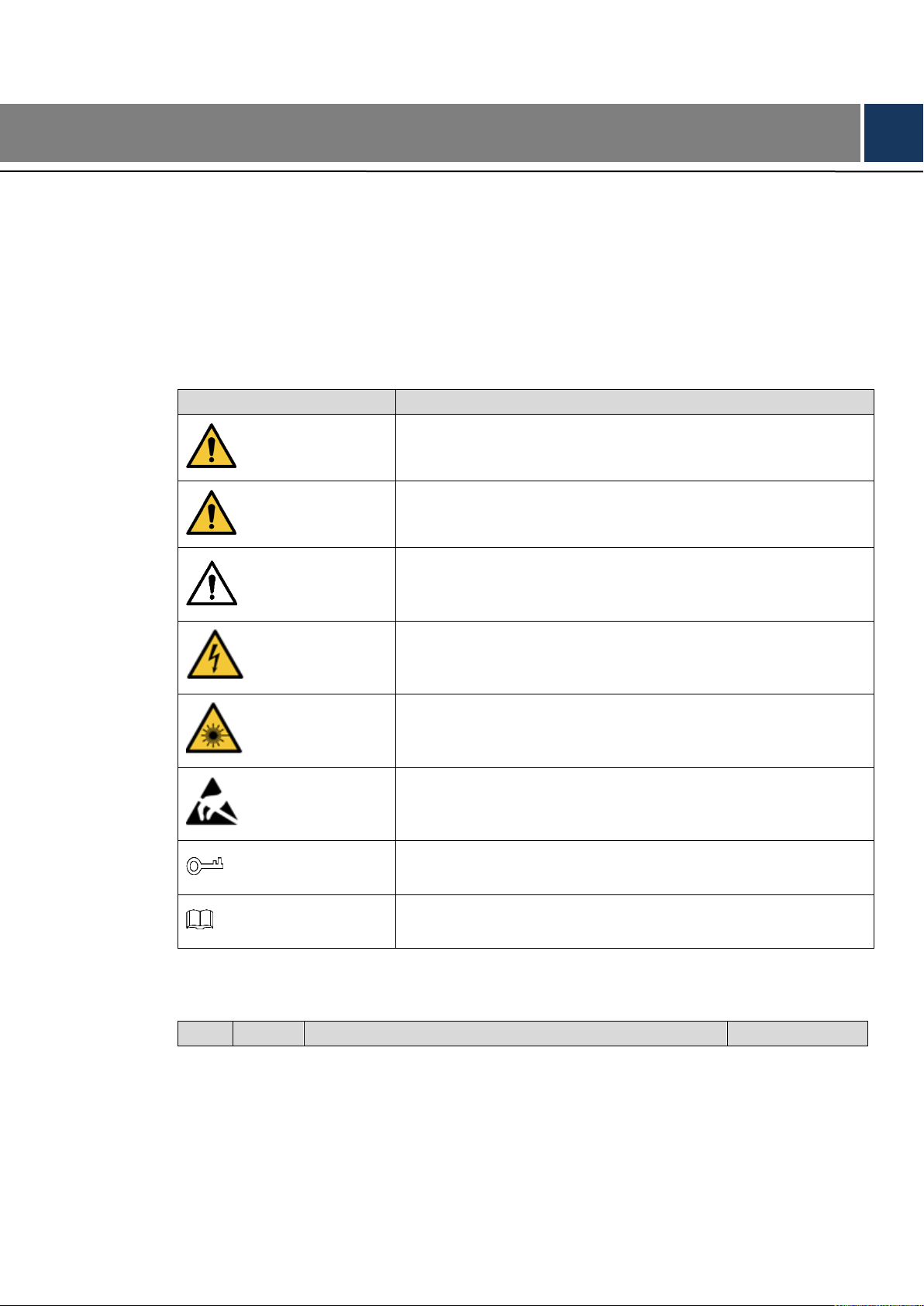
Signal Words
Meaning
DANGER
Indicates a high potential hazard which, if not avoided, will result
in death or serious injury.
WARNING
Indicates a medium or low potential hazard which, if not
avoided, could result in slight or moderate injury.
CAUTION
Indicates a potential risk which, if not avoided, could result in
property damage, data loss, lower performance, or
unpredictable result.
ELECTRICITY
Indicates dangerous high voltage.
Take care to avoid coming into contact with electricity.
LASER BEAM
Indicates a laser radiation hazard.
Take care to avoid exposure to a laser beam.
ESD
Electrostatic Sensitive Devices.
Indicates a device that is sensitive to electrostatic discharge.
TIPS
Provides methods to help you solve a problem or save you time.
NOTE
Provides additional information as the emphasis and
supplement to the text.
No.
Version
Revision Content
Release Time
General
This user’s manual (hereinafter referred to be "the Manual") introduces the functions and
operations of the NVR (EZ-IP 2.0) devices (hereinafter referred to be "the Device").
Safety Instructions
The following categorized signal words with defined meaning might appear in the Manual.
Foreword
Revision History
VIII
Page 10

No.
Version
Revision Content
Release Time
1
V1.0.0
First Release.
November, 2017
2
V1.1.0
April, 2018
3
V1.1.1
Add privacy protection notice.
May, 2018
4
V1.1.2
Add FCC.
Add new models:
NVR1A-4P/1A-8P/1AHS/1AHS-4P/1AHS-8P/2A16.
July, 2018
5
V1.2.0
Add models: NVR1BHC/E, NVR1BHC-4P/E,
NVR1BHS-8P/E.
Update relevant information about the added
models.
GDPR update.
August, 2018
Privacy Protection Notice
As the device user or data controller, you might collect personal data of others such as face,
fingerprints, car plate number, Email address, phone number, GPS and so on. You need to be in
compliance with the local privacy protection laws and regulations to protect the legitimate rights
and interests of other people by implementing measures including but not limited to: providing
clear and visible identification to inform data subject the existence of surveillance area and
providing related contact.
About the Manual
The Manual is for reference only. If there is inconsistency between the Manual and the
actual product, the actual product shall prevail.
We are not liable for any loss caused by the operations that do not comply with the Manual.
The Manual would be updated according to the latest laws and regulations of related
regions. For detailed information, see the paper manual, CD-ROM, QR code or our official
website. If there is inconsistency between paper manual and the electronic version, the
electronic version shall prevail.
All the designs and software are subject to change without prior written notice. The product
updates might cause some differences between the actual product and the Manual. Please
contact the customer service for the latest program and supplementary documentation.
There still might be deviation in technical data, functions and operations description, or
errors in print. If there is any doubt or dispute, please refer to our final explanation.
Upgrade the reader software or try other mainstream reader software if the Guide (in PDF
format) cannot be opened.
All trademarks, registered trademarks and the company names in the Manual are the
properties of their respective owners.
IX
Page 11

Please visit our website, contact the supplier or customer service if there is any problem
occurred when using the device.
If there is any uncertainty or controversy, please refer to our final explanation.
X
Page 12

Important Safeguards and Warnings
The following description is the correct application method of the device. Read the manual
carefully before use to prevent danger and property loss. Strictly conform to the manual during
application and keep it properly after reading.
Operating Requirement
Don’t place and install the device in an area exposed to direct sunlight or near heat
generating device.
Don’t install the device in a humid, dusty or fuliginous area.
Keep its horizontal installation, or install it at stable places, and prevent it from falling.
Don’t drip or splash liquids onto the device; don’t put on the device anything filled with
liquids, in order to prevent liquids from flowing into the device.
Install the device at well-ventilated places; don’t block its ventilation opening.
Use the device only within rated input and output range.
Don’t dismantle the device arbitrarily.
Transport, use and store the device within allowed humidity and temperature range.
Power Requirement
Make sure to use batteries according to requirements; otherwise, it may result in fire,
explosion or burning risks of batteries!
To replace batteries, only the same type of batteries can be used.
The product shall use electric wires (power wires) recommended by this area, which shall
be used within its rated specification.
Make sure to use standard power adapter matched with this device. Otherwise, the user
shall undertake resulting personnel injuries or device damages.
Use power supply that meets SELV (safety extra low voltage) requirements, and supply
power with rated voltage that conforms to Limited Power Source in IEC60950-1. For
specific power supply requirements, please refer to device labels.
Products with category I structure shall be connected to grid power output socket, which is
equipped with protective grounding.
Appliance coupler is a disconnecting device. During normal use, please keep an angle that
facilitates operation.
XI
Page 13

1 Features and Specifications
Cloud
Upgrade
For the NVR connected with the Internet, it supports online upgrade to
update applications.
Real-time
Surveillance
VGA, HDMI port. Connect to monitor to realize real-time surveillance.
Short-cut menu when preview.
Support popular PTZ decoder control protocols. Support preset, tour
and pattern.
Playback
Support each channel real-time record independently, and at the same
time it can support search, forward play, network monitor, record search,
download and etc.
Support various playback modes: slow play, fast play, backward play
and frame by frame play.
Support time title overlay so that you can view event accurate occurred
time
Support specified zone enlargement.
User
Management
Each group has different management powers that can be edited freely.
Every user belongs to an exclusive group.
Storage
Via corresponding setup (such as alarm setup and schedule setup), you
can backup related audio/video data in the network video recorder.
Support Web record and record local video and storage the file in the
client end.
Network
Monitor
Through network, sending audio/video data compressed by IPC to
client-ends, then the data will be decompressed and display.
Support max 128 connections at the same time.
Transmit audio/video data by HTTP, TCP, UDP, RTP/RTCP and etc.
Support WEB access in WAN/LAN.
Window Split
Adopt the video compression and digital process to show several
windows in one monitor. Support 1/4/8/9-window display (depending on
1.1 Overview
This series NVR is an entry-level network video recorder. This series product support local preview,
multiple-window display, recorded file local storage, remote control and mouse shortcut menu operation,
and remote management and control function.
This series product supports center storage, front-end storage and client-end storage. The monitor zone
in the front-end can be set in anywhere. Working with other front-end devices such as IPC, this series
product can establish a strong surveillance network via the CMS. In the network system, there is only one
network cable from the monitor center to the monitor zone in the whole network. There is no audio/video
cable from the monitor center to the monitor zone. The whole project is featuring of simple connection,
low-cost, low maintenance work.
This series NVR can be widely used in many areas such as public security, water conservancy,
transportation and education.
1.2 Features
1
Page 14

product channel amount) when preview and 1/4/9/16-window
(depending on product channel amount) display when playback.
Record
Support normal/motion detect/alarm record function. Save the recorded
files in the HDD, USB device, client-end PC, or network storage server.
You can search or playback the saved files at the local-end or via the
Web/USB device.
Backup
Support network backup, USB2.0 record backup function, the recorded
files can be saved in network storage server, peripheral USB2.0
device, burner and etc.
Network
Management
Supervise NVR configuration and control power via Ethernet.
Support management via WEB.
Peripheral
Equipment
Management
Support peripheral equipment management such as protocol setup and
port connection.
Auxiliary
Support switch between NTSC and PAL.
Support real-time system resources information and running statistics
display.
Support log file.
Local GUI output. Shortcut menu operation via mouse.
Play the video/audio from the network camera or NVS remotely.
Model
NVR1A-4P Series
NVR1A-8P Series
System
System
Resources
4/8-ch series product support 4/8 HD connection respectively. Total
bandwidth supports 80Mbps.
OS
Embedded Linux real-time operation system
Operation
Interface
WEB/Local GUI
Decode
Video Decode
Type
Smart H.264+/H.264
Decode
Capability
Max 4-ch 1080P 30fps or 8-ch 720P 30fps or 8-ch D1 30fps
Video
Video Input
4/8-ch network compression video input
Video Output
1-channel VGA analog video output
1.3 Specifications
1.3.1 NVR1A-4P/1A-8P Series
2
Page 15

Model
NVR1A-4P Series
NVR1A-8P Series
HDMI
1-ch HDMI output. Version number is 1.4
Window Split
1/4/8/9-window
Audio
Audio Input
1-ch bidirectional talk input
Audio Output
1-ch bidirectional talk output
Audio
Compression
Standard
G.711a
Alarm
Alarm Input
N/A
Alarm Output
N/A
Function
Storage
1 built-in SATA port
Multiple-Chann
el Playback
Max 8-channel D1 or 8-channel 720P or 4-channel 1080P playback
Port and
Indicator
RS232 Port
N/A
RS485 Port
N/A
USB Port
2 peripheral USB2.0 ports.
Network
Connection
1 RJ45 10/100Mbps self-adaptive Ethernet port.
PoE
4
8
Power Port
1 power socket. Power adapter
power supplying mode. DC 48V
power.
1 power socket. Power adapter
power supplying mode. DC 48V
power.
3
Page 16

Model
NVR1A-4P Series
NVR1A-8P Series
Power Button
N/A
Power On-off
Button
N/A
IR Receiver
Window
N/A
Clock
Built-in clock.
Indicator Light
One power status indicator light.
One network status indicator light.
One HDD status indicator light.
General
Power
Consumption
<10W (No HDD)
Working
Temperature
﹣10℃~﹢55℃
Working
Humidity
10℅~90℅
Air pressure
86kPa~106kPa
Dimension
205mm×206.75mm×45.2mm
425mm×95mm×260mm
Weight
0.5kg~2kg (No HDD)
Installation
Mode
Desk installation
Model
NVR1AHS Series
NVR1AHS-4P Series
NVR1AHS-8P Series
System
System
Resources
4/8-ch series product
support 4/8 HD
connection
respectively. Total
bandwidth supports
80Mbps.
4/8-ch series product support 4/8 HD
connection respectively. Total bandwidth
supports 80Mbps.
OS
Embedded Linux real-time operation system
Operation
Interface
WEB/Local GUI
1.3.2 NVR1AHS/1AHS-4P/1AHS-8P Series
4
Page 17

Model
NVR1AHS Series
NVR1AHS-4P Series
NVR1AHS-8P Series
Decode
Video Decode
Type
Smart H.264+/H.264
Decode
Capability
Max 4-ch 1080P 30fps or 8-ch 720P 30fs or 8-ch D1 30fps
Video
Video Input
4/8-ch network
compression video
input
4/8-ch network compression video input
Video Output
1-channel VGA analog video output
HDMI
1-ch HDMI output. Version number is 1.4
Window Split
1/4/8/9-window
1/4/8/9-window
Audio
Audio Input
1-ch bidirectional talk input
Audio Output
1-ch bidirectional talk output
Audio
Compression
Standard
G.711a
Alarm
Alarm Input
N/A
Alarm Output
N/A
Function
Storage
1 built-in SATA port
Multiple-Chann
el Playback
Max 4-channel 1080P or 8-channel 720P or 8-channel D1 playback
Port and
Indicator
RS232 Port
N/A
RS485 Port
N/A
USB Port
2 peripheral USB2.0 ports.
Network
Connection
1 RJ45 10/100Mbps self-adaptive Ethernet port.
PoE Port
N/A
4
8
Power Port
1 power socket.
Power adapter
power supplying
mode. DC 12V
power.
1 power socket.
Power adapter
power supplying
mode. DC 48V
power.
1 power socket.
Power adapter
power supplying
mode. DC 48V
power.
Power Button
N/A
5
Page 18

Model
NVR1AHS Series
NVR1AHS-4P Series
NVR1AHS-8P Series
Power On-off
Button
N/A
IR Receiver
Window
N/A
Clock
Built-in clock.
Indicator Light
One power status indicator light.
One network status indicator light.
One HDD status indicator light.
General
Power
Consumption
<10W (No HDD)
Working
Temperature
﹣10℃~﹢55℃
Working
Humidity
10℅~90℅
Air pressure
86kPa~106kPa
Dimension(W×
D×H)
260mm×220mm×44mm
Weight
0.7kg~0.8kg (No HDD)
Installation
Mode
Desk installation
Model
NVR2A16 Series
System
System
Resources
16-ch series product support 16 HD connection respectively. Total
bandwidth supports 80Mbps.
OS
Embedded Linux real-time operation system
Operation
Interface
WEB/Local GUI
Decode
Video Decode
Type
Smart H.264+/H.264
Decode
Capability
Max 4-ch 1080P 30fps or 8-ch 720P 30fs or 8-ch D1 30fps
Video
Video Input
16-ch network compression video input
Video Output
1-channel VGA analog video output
HDMI
1-ch HDMI output. Version number is 1.4
Window Split
1/4/8/9/16-window
Audio
Audio Input
1-ch bidirectional talk input
1.3.3 NVR2A16 Series
6
Page 19

Model
NVR2A16 Series
Audio Output
1-ch bidirectional talk output
Audio
Compression
Standard
G.711a
Alarm
Alarm Input
N/A
Alarm Output
N/A
Function
Storage
2 built-in SATA ports
Multiple-Chann
el Playback
Max 4-channel 1080P or 8-channel 720P or 8-channel D1 playback
Port and
Indicator
RS232 Port
N/A
RS485 Port
N/A
USB Port
2 peripheral USB2.0 ports.
Network
Connection
1 RJ45 10/100Mbps self-adaptive Ethernet port.
PoE Port
N/A
Power Port
1 power socket. Power adapter power supplying mode. DC 12V
power.
Power Button
N/A
Power On-off
Button
N/A
IR Receiver
Window
N/A
Clock
Built-in clock.
Indicator Light
One power status indicator light.
One network status indicator light.
One HDD status indicator light.
General
Power
Consumption
<10W (No HDD)
Working
Temperature
﹣10℃~﹢55℃
Working
Humidity
10℅~90℅
Air pressure
86kPa~106kPa
Dimension(W×
D×H)
375mm×287mm×52mm
Weight
1.5kg~2.5kg (No HDD)
7
Page 20

Model
NVR2A16 Series
Installation
Mode
Desk installation
1.3.4 NVR1B04/L, NVR1B08/L, NVR1B04-4P/L Series
Model
NVR1B04/L Series
NVR1B08/L Series
NVR1B04-4P/L
Series
System
System
Resources
4/8-ch series product support 4/8 HD connection respectively. Total
bandwidth supports 48Mbps.
OS
Embedded Linux real-time operation system
Operation
Interface
WEB/Local GUI
Decode
Video Decode
Type
H.265/H.264
Decode
Capability
Max 2-ch 1080P 30fps or 4-ch 720P 30fps or 8-ch D1 30fps
Video
Video Input
4/8-ch network compression video input
Video Output
1-channel VGA analog video output
1-ch HDMI output. Version number is 1.4
Window Split
1/4-window
1/4/8/9-window
1/4-window
Audio
Audio Input
N/A
Audio Output
N/A
Audio
Compression
Standard
N/A
8
Page 21

Model
NVR1B04/L Series
NVR1B08/L Series
NVR1B04-4P/L
Series
Alarm
Alarm Input
N/A
Alarm Output
N/A
Function
Storage
1 built-in SATA port
Multiple-Chann
el Playback
Max 4-channel playback
Port and
Indicator
RS232 Port
N/A
RS485 Port
N/A
USB Port
2 peripheral USB2.0 ports.
Network
Connection
1 RJ45 10/100Mbps self-adaptive Ethernet port.
PoE
N/A
N/A
4 Ports
Power Port
1 power socket. Power adapter power
supplying mode. DC 12V power.
1 power socket.
Power adapter
power supplying
mode. DC 48V
power.
Power Button
N/A
Power On-off
Button
N/A
IR Receiver
Window
N/A
Clock
Built-in clock.
Indicator Light
One power status indicator light.
One network status indicator light.
One HDD status indicator light.
9
Page 22

Model
NVR1B04/L Series
NVR1B08/L Series
NVR1B04-4P/L
Series
General
Power
Consumption
<10W (No HDD)
Working
Temperature
﹣10℃~﹢55℃
Working
Humidity
10℅~90℅
Air pressure
86kPa~106kPa
Dimension
204.6mm×204.6mm×45.2mm
Weight
0.4kg~0.65kg (No HDD)
Installation
Mode
Desk installation
Model
NVR1B04HS/L
Series
NVR1B08HS/L
Series
NVR1B04HS-4P/L
Series
System
System
Resources
4/8-ch series product support 4/8 HD connection respectively. Total
bandwidth supports 48Mbps.
OS
Embedded Linux real-time operation system
Operation
Interface
WEB/Local GUI
Decode
Video Decode
Type
H.265/H.264
Decode
Capability
Max 2-ch 1080P 30fps or 4-ch 720P 30fs or 8-ch D1 30fps
Video
Video Input
4/8-ch network compression video input
Vieo Output
1-channel VGA analog video output
1-ch HDMI output. Version number is 1.4
Window Split
1/4-window
1/4/8/9-window
1/4-window
Audio
Audio Input
N/A
Audio Output
N/A
Audio
N/A
1.3.5 NVR1B04HS/L, NVR1B08HS/L, NVR1B04HS-4P/L Series
10
Page 23

Model
NVR1B04HS/L
Series
NVR1B08HS/L
Series
NVR1B04HS-4P/L
Series
Compression
Standard
Alarm
Alarm Input
N/A
Alarm Output
N/A
Function
Storage
1 built-in SATA port
Multiple-Chann
el Playback
Max 4-channel playback
Port and
Indicator
RS232 Port
N/A
RS485 Port
N/A
USB Port
2 peripheral USB2.0 ports.
Network
Connection
1 RJ45 10/100Mbps self-adaptive Ethernet port.
PoE Port
N/A
N/A
4 ports
Power Port
1 power socket. Power adapter power
supplying mode. DC 12V power.
1 power socket.
Power adapter
power supplying
mode. DC 48V
power.
Power Button
N/A
Power On-off
Button
N/A
IR Receiver
Window
N/A
Clock
Built-in clock.
Indicator Light
One power status indicator light.
One network status indicator light.
One HDD status indicator light.
General
Power
Consumption
<10W (No HDD)
Working
Temperature
﹣10℃~﹢55℃
Working
Humidity
10℅~90℅
Air pressure
86kPa~106kPa
Dimension(W×
D×H)
260mm×229.3mm×47.6mm
11
Page 24

Model
NVR1B04HS/L
Series
NVR1B08HS/L
Series
NVR1B04HS-4P/L
Series
Weight
0.9kg~1kg (No HDD)
Installation
Mode
Desk installation
Model
NVR1B04 Series
NVR1B08 Series
NVR1B04-4PSeries
System
System
Resources
4/8-ch series product support 4/8 HD connection respectively. Total
bandwidth supports 80Mbps.
OS
Embedded Linux real-time operation system
Operation
Interface
WEB/Local GUI
Decode
Video Decode
Type
H.265/H.264
Decode
Capability
Max 1-ch 4K 30fps or 4-ch 1080P 30fps or 8-ch 720P 30fs
Video
Video Input
4/8-ch network compression video input
Video Output
1-channel VGA analog video output
1-ch HDMI output. Version number is 1.4
Window Split
1/4/8/9-window
Audio
Audio Input
1-ch bidirectional talk input
Audio Output
1-ch bidirectional talk input
Audio
Compression
Standard
PCM、G.711a、G711u
Alarm
Alarm Input
N/A
Alarm Output
N/A
Function
Storage
1 built-in SATA port
Multiple-Chann
el Playback
Max 4-channel playback
Port and
Indicator
RS232 Port
N/A
RS485 Port
N/A
USB Port
2 peripheral USB2.0 ports.
1.3.6 NVR1B04, NVR1B08, NVR1B04-4P Series
12
Page 25

Model
NVR1B04 Series
NVR1B08 Series
NVR1B04-4PSeries
Network
Connection
1 RJ45 10/100Mbps self-adaptive Ethernet port.
PoE Port
N/A
N/A
4 ports
Power Port
1 power socket. Power adapter power
supplying mode. DC 12V power.
1 power socket.
Power adapter
power supplying
mode. DC 48V
power.
Power Button
N/A
Power On-off
Button
N/A
IR Receiver
Window
N/A
Clock
Built-in clock.
Indicator Light
One power status indicator light.
One network status indicator light.
One HDD status indicator light.
General
Power
Consumption
<10W (No HDD)
Working
Temperature
﹣10℃~﹢55℃
Working
Humidity
10℅~90℅
Air pressure
86kPa~106kPa
Dimension(W×
D×H)
204.6mm× 206.6mm×45.2mm
Weight
0.9kg~1kg (No HDD)
Installation
Mode
Desk installation
Model
NVR1B04HS
Series
NVR1B08HS
Series
NVR1B04HS4P Series
NVR1B08HS8P Series
System
System
Resources
4/8-ch series product support 4/8 HD connection respectively. Total
bandwidth supports 80Mbps.
OS
Embedded Linux real-time operation system
Operation
Interface
WEB/Local GUI
1.3.7 NVR1B04HS, NVR1B08HS, NVR1B04HS-4P, NVR1B08HS-8P Series
13
Page 26

Model
NVR1B04HS
Series
NVR1B08HS
Series
NVR1B04HS4P Series
NVR1B08HS8P Series
Decode
Video Decode
Type
H.265/H.264
Decode
Capability
Max 1-ch 4K 30fps or 4-ch 1080P 30fps or 8-ch 720P 30fs
Video
Video Input
4/8-ch network compression video input
Video Output
1-channel VGA analog video output
1-ch HDMI output. Version number is 1.4
Window Split
1/4-window
1/4/8/9-window
1/4-window
1/4/8/9-window
Audio
Audio Input
N/A
Audio Output
N/A
Audio
Compression
Standard
PCM、G.711a、G711u
Alarm
Alarm Input
N/A
Alarm Output
N/A
Function
Storage
1 built-in SATA port
Multiple-Chann
el Playback
Max 4-channel playback
Port and
Indicator
RS232 Port
N/A
RS485 Port
N/A
USB Port
2 peripheral USB2.0 ports.
Network
Connection
1 RJ45 10/100Mbps self-adaptive Ethernet port.
1 RJ45
10/100/1000M
bps
self-adaptive
Ethernet port.
PoE Port
N/A
N/A
4 ports
8 ports
Power Port
1 power socket. Power adapter
power supplying mode. DC 12V
power.
1 power socket. Power adapter
power supplying mode. DC 48V
power.
Power Button
N/A
Power On-off
Button
N/A
14
Page 27

Model
NVR1B04HS
Series
NVR1B08HS
Series
NVR1B04HS4P Series
NVR1B08HS8P Series
IR Receiver
Window
N/A
Clock
Built-in clock.
Indicator Light
One power status indicator light.
One network status indicator light.
One HDD status indicator light.
General
Power
Consumption
<10W (No HDD)
Working
Temperature
﹣10℃~﹢55℃
Working
Humidity
10℅~90℅
Air pressure
86kPa~106kPa
Dimension(W×
D×H)
260mm×229.3mm×47.6mm
Weight
0.9kg~1kg (No HDD)
Installation
Mode
Desk installation
Model
NVR2B16 Series
System
System
Resources
16-ch series product support 16 HD connection respectively. Total
bandwidth supports 80Mbps.
OS
Embedded Linux real-time operation system
Operation
Interface
WEB/Local GUI
Decode
Video Decode
Type
Smart H.265/H.264
Decode
Capability
Max 4-ch 1080P 30fps or 8-ch 720P 30fs
Video
Video Input
16-ch network compression video input
Video Output
1-channel VGA analog video output
1-ch HDMI output. Version number is 1.4
Window Split
1/4/8/9/16-window
Audio
Audio Input
1-ch bidirectional talk input
1.3.8 NVR2B16 Series
15
Page 28

Model
NVR2B16 Series
Audio Output
1-ch bidirectional talk output
Audio
Compression
Standard
PCM、G.711a、G711u
Alarm
Alarm Input
N/A
Alarm Output
N/A
Function
Storage
2 built-in SATA ports
Multiple-Chann
el Playback
Max 4-channel playback
Port and
Indicator
RS232 Port
N/A
RS485 Port
N/A
USB Port
2 peripheral USB2.0 ports.
Network
Connection
1 RJ45 10/100Mbps self-adaptive Ethernet port.
PoE Port
N/A
Power Port
1 power socket. Power adapter power supplying mode. DC 12V
power.
Power Button
N/A
Power On-off
Button
N/A
IR Receiver
Window
N/A
Clock
Built-in clock.
Indicator Light
One power status indicator light.
One network status indicator light.
One HDD status indicator light.
General
Power
Consumption
<10W (No HDD)
Working
Temperature
﹣10℃~﹢55℃
Working
Humidity
10℅~90℅
Air pressure
86kPa~106kPa
Dimension(W×
D×H)
375mm×282.6mm×53mm
Weight
1.5kg~2.5kg (No HDD)
16
Page 29

Model
NVR2B16 Series
Installation
Mode
Desk installation
Model
NVR1BHC/E
NVR1BHC-4P/E
System
Host
Processor
Industrial grade embedded microcontroller
OS
Embedded Linux operation system
System
Resources
4-channel/8-channel NVR supports 4-channel/8-channel HD input
respectively
Operation
Interface
Web, local GUI
Audio
Audi Input
N/A
Audio Output
N/A
Audio
Compression
Standard
PCM, G711a, G711u
Video
Video Input
4-channel and 8-channel network compression video input
Video Output
1-channel VGA analog video output; 1-channel HDMI video output.
Same source output.
Video
Compression
Standard
Not support.
Window Split
1/4/8/9-window
Alarm
Alarm Input
N/A
Alarm Output
N/A
Decode
Decoding Type
H.264; H265; MPEG4; smart264; smart265
Decoding
Capability
1-channel 6M, 1-channel 5M, 2-channel 4M, 4-channel 1080P,
8-channel 720P
Function
Record Mode
Manual record, motion detect record, schedule record and alarm
record. Record priority: Manual record > alarm record > motion
detect record > schedule record.
Multi-Channel
Playback
Max 4-channel 1080P playback at the same time
Motion Detect
Each video supports PAL 396(22*18) detection zones, support
multiple sensivity levels from level 1 to level 6
Tampering
Each channel supports 4 tampering zones
Record
Storage
Local HDD, network, etc.
Backup Mode
External USB storage device
Ports
Network
Protocol
IPv4, IPv6, HTTP, NTP, DNS, ONVIF
SATA Port
One
1.3.9 NVR1BHC/E, NVR1BHC-4P/E Series
17
Page 30

Model
NVR1BHC/E
NVR1BHC-4P/E
eSATA Port
N/A
RS232 Port
N/A
RS485 Port
N/A
USB Port
Two USB 2.0
HDMI Port
One
VGA Port
One
Network Port
One RJ45 10/100Mbps self-adaptive Ethernet port
Power on-off
Button
N/A
Power Button
N/A
IR Receiver
Window
N/A
Clock
One built-in real-time clock
Indicator
N/A
General
Power input
DC12V 1.5A
DC48V 1.25A
Power
consumption
2.57W (no HDD)
3.61W (no HDD)
Working temp
-10℃ to +45℃
Working
humidity
10% to 90%
Atmospheric
pressure
86kpa to 106kpa
Dimension
192 mm * 197 mm * 42 mm
Weight
1.15kg
1.46kg
Installation
mode
Desktop
Model
NVR1BHS-8P/E
System
Host
Processor
Industrial grade embedded microcontroller
OS
Embedded Linux operation system
System
Resources
8-channel NVR supports 8-channel HD input respectively
Operation
Interface
Web, local GUI
Audio
Audi Input
N/A
Audio Output
N/A
Audio
Compression
Standard
PCM, G711a, G711u
Video
Video Input
8-channel network compression video input
Video Output
1-channel VGA analog video output; 1-channel HDMI video output.
Same source output.
1.3.10 NVR1BHS-8P/E Series
18
Page 31

Model
NVR1BHS-8P/E
Video
Compression
Standard
Not support.
Window Split
1/4/8/9-window
Alarm
Alarm Input
N/A
Alarm Output
N/A
Decode
Decoding Type
H.264; H265; MPEG4; smart264; smart265
Decoding
Capability
1-channel 6M, 1-channel 5M, 2-channel 4M, 4-channel 1080P,
8-channel 720P
Function
Record Mode
Manual record, motion detect record, schedule record and alarm
record. Record priority: Manual record > alarm record > motion
detect record > schedule record.
Multi-Channel
Playback
Max 4-channel 1080P playback at the same time
Motion Detect
Each video supports PAL 396(22*18) detection zones, support
multiple sensivity levels from level 1 to level 6
Tampering
Each channel supports 4 tampering zones
Record
Storage
Local HDD, network, etc.
Backup Mode
External USB storage device
Ports
Network
Protocol
IPv4, IPv6, HTTP, NTP, DNS, ONVIF
SATA Port
One
eSATA Port
N/A
RS232 Port
N/A
RS485 Port
N/A
USB Port
Two USB 2.0
HDMI Port
One
VGA Port
One
Network Port
One RJ45 10/100Mbps self-adaptive Ethernet port
Power on-off
Button
N/A
Power Button
N/A
IR Receiver
Window
N/A
Clock
One built-in real-time clock
Indicator
N/A
General
Power input
DC48V/2A
Power
consumption
4.29W (no HDD)
Working temp
-10℃ to +45℃
Working
humidity
10% to 90%
19
Page 32

Model
NVR1BHS-8P/E
Atmospheric
pressure
86kpa to 106kpa
Dimension
221 mm * 260 mm * 48 mm
Weight
2kg
Installation
mode
Desktop
20
Page 33

2 Front Panel and Rear Panel
SN
Name
Function
1
HDD status indictor light
The red light becomes on when HDD is abnormal.
2
Power indicator light
The red light becomes on when the power
connection is OK.
3
Network status indicator
light
The red light becomes on when the network
connection is abnormal.
Icon
Name
Function
HDD
HDD status indicator
light
The blue light is on when the HDD is malfunction.
NOTE
The following front panel and rear panel figures are for reference only. The actual product shall prevail.
2.1 Front Panel
2.1.1 NVR1A-4P, NVR1A-8P, NVR1B04 (/L), NVR1B08 (/L), NVR1B04-4P (/L) Series
The front panel is shown as in Figure 2-1.
Figure 2-1
Please refer to the following sheet for detailed information.
2.1.2 NVR1AHS, NVR1AHS-4P, NVR1AHS-8P, NVR2A16, NVR1B04HS (/L),
NVR1B08HS (/L), NVR1B04HS-4P (/L), NVR1B08HS-8P, NVR2B16 Series
The front panel is shown as in Figure 2-2.
Please refer to the following sheet for front panel button information.
Figure 2-2
21
Page 34

Icon
Name
Function
NET
Network status indicator
light
The blue light is on when the network connection is
abnormal.
POWER
Power status indicator light
The blue light is on when the power connection is
OK.
USB port
Connect to peripheral USB storage device, mouse
and etc.
2.1.3 NVR1BHC/E, NVR1BHC-4P/E, NVR1BHS-8P/E Series
The NVR1BHC/E, NVR1BHC-4P/E series front panel is shown as in Figure 2-3.
Figure 2-3
The NVR1BHS-8P/E series front panel is shown as in Figure 2-4.
Figure 2-4
2.2 Rear Panel
2.2.1 NVR1B04/L, NVR1B08/L, NVR1B04-4P/L Series
The NVR1B04/L, NVR1B08/L series rear panel is shown as in Figure 2-5.
Figure 2-5
The NVR1B04-4P/L series rear panel is shown as in Figure 2-6.
Figure 2-6
2.2.2 NVR1A-4P, NVR1A-8P, NVR1B04, NVR1B08, NVR1B04-4P Series
22
Page 35

Port Name
Connection
Function
Power input port
Power socket
For NVR1B04-4P, input DC 48V/1.25A.
Network port
10M/100Mbps self-adaptive Ethernet port. Connect to the
network cable.
The NVR1A-4P series rear panel is shown as in Figure 2-7.
Figure 2-7
The NVR1A-8P series rear panel is shown as in Figure 2-8.
Figure 2-8
The NVR1B04/1B08 series rear panel is shown as in Figure 2-9.
Figure 2-9
The NVR1B04-4P series rear panel is shown as in Figure 2-10.
Figure 2-10
Please refer to the following sheet for detailed information.
23
Page 36

Port Name
Connection
Function
USB port
USB port. Connect to mouse, USB storage device and
etc.
HDMI
High Definition
Media Interface
High definition audio and video signal output port. It
transmits uncompressed high definition video and
multiple-channel data to the HDMI port of the display
device. HDMI version is 1.4.
VGA
VGA video output
port
VGA video output port. Output analog video signal. It can
connect to the monitor to view analog video.
MIC IN
Audio input port
Bidirectional talk input port. It is to receive the analog
audio signal output from the devices such as microphone,
pickup.
MIC OUT
Audio output port
Audio output port. It is to output the analog audio signal to
the devices such as the sound box.
Bidirectional talk output.
Audio output on 1-window video monitor.
Audio output on 1-window video playback.
GND
Ground end
PoE
PORTS
PoE port
Built-in switch. Support PoE function.
For PoE series product, you can use this port to provide
power to the network camera.
2.2.3 NVR1B04HS/L, NVR1B08HS/L, NVR1B04HS-4P/L Series
The NVR1B04HS/L, NVR1B08HS/L series rear panel is shown as below. See Figure 2-11.
Figure 2-11
The NVR1B04HS-4P/L series rear panel is shown as below. See Figure 2-12.
Figure 2-12
24
Page 37

2.2.4 NVR1AHS, NVR1AHS-4P, NVR1AHS-8P, NVR1B04HS, NVR1B08HS,
NVR1B04HS-4P, NVR1B08HS-8P Series
The NVR1AHS series rear panel is shown as below. See Figure 2-13.
Figure 2-13
The NVR1AHS-4P series rear panel is shown as below. See Figure 2-14.
Figure 2-14
The NVR1AHS-8P series rear panel is shown as below. See Figure 2-15.
Figure 2-15
The NVR1B04HS, NVR1B08HS series rear panel is shown as below. See Figure 2-16.
Figure 2-16
The NVR1B04HS-4P series rear panel is shown as below. See Figure 2-17.
Figure 2-17
The NVR1B08HS-8P series rear panel is shown as below. See Figure 2-18.
25
Page 38

Figure 2-18
Port Name
Connection
Function
Power input port
Power socket.
For NVR1B04/08HS, input DC 12V/2A.
For NVR1BHS-4P, input DC 48V/1.25A.
For NVR1BHS-8P, input DC 48V/2A.
Network port
10M/100Mbps self-adaptive Ethernet port. Connect to the
network cable.
USB port
USB port. Connect to mouse, USB storage device and
etc.
HDMI
High Definition
Media Interface
High definition audio and video signal output port. It
transmits uncompressed high definition video and
multiple-channel data to the HDMI port of the display
device. HDMI version is 1.4.
VGA
VGA video output
port
VGA video output port. Output analog video signal. It can
connect to the monitor to view analog video.
MIC IN
Audio input port
Bidirectional talk input port. It is to receive the analog
audio signal output from the devices such as microphone,
pickup.
MIC OUT
Audio output port
Audio output port. It is to output the analog audio signal to
the devices such as the sound box.
Bidirectional talk output.
Audio output on 1-window video monitor.
Audio output on 1-window video playback.
GND
Ground end
PoE
PORTS
PoE port
Built-in switch. Support PoE function.
For PoE series product, you can use this port to provide
power to the network camera.
Please refer to the following sheet for detailed information.
2.2.5 NVR2A16, NVR2B16 Series
The NVR2A16 series rear panel is shown as below. See Figure 2-19.
26
Page 39

Figure 2-19
Port Name
Connection
Function
Power input port
Power socket.
Network port
10M/100Mbps self-adaptive Ethernet port. Connect to the
network cable.
USB port
USB port. Connect to mouse, USB storage device and
etc.
HDMI
High Definition
Media Interface
High definition audio and video signal output port. It
transmits uncompressed high definition video and
multiple-channel data to the HDMI port of the display
device. HDMI version is 1.4.
VGA
VGA video output
port
VGA video output port. Output analog video signal. It can
connect to the monitor to view analog video.
MIC IN
Audio input port
Bidirectional talk input port. It is to receive the analog
audio signal output from the devices such as microphone,
pickup.
MIC OUT
Audio output port
Audio output port. It is to output the analog audio signal to
the devices such as the sound box.
Bidirectional talk output.
Audio output on 1-window video monitor.
Audio output on 1-window video playback.
GND
Ground end
The NVR2B16 series rear panel is shown as below. See Figure 2-20.
Figure 2-20
Please refer to the following sheet for detailed information.
2.2.6 NVR1BHC/E, NVR1BHC-4P/E, NVR1BHS-8P/E Series
The NVR1BHC/E series rear panel is shown as below. See Figure 2-21.
The NVR1BHC-4P/E series rear panel is shown as below. See Figure 2-22.
Figure 2-21
27
Page 40

Figure 2-22
Port Name
Connection
Function
Power input port
Power socket.
PoE
PORTS
PoE port
Built-in switch. Support PoE function.
For PoE series product, you can use this port to provide
power to the network camera.
Network port
10M/100Mbps self-adaptive Ethernet port. Connect to the
network cable.
VGA
VGA video output
port
VGA video output port. Output analog video signal. It can
connect to the monitor to view analog video.
MIC IN
Audio input port
Bidirectional talk input port. It is to receive the analog
audio signal output from the devices such as microphone,
pickup.
MIC OUT
Audio output port
Audio output port. It is to output the analog audio signal to
the devices such as the sound box.
Bidirectional talk output.
Audio output on 1-window video monitor.
Audio output on 1-window video playback.
HDMI
High Definition
Media Interface
High definition audio and video signal output port. It
transmits uncompressed high definition video and
multiple-channel data to the HDMI port of the display
device.
USB port
USB port. Connect to mouse, USB storage device and
etc.
GND
Ground end
The NVR1BHS-8P/E series rear panel is shown as below. See Figure 2-23
Figure 2-23
Please refer to the following sheet for detailed information.
2.3 Bidirectional talk
28
Page 41

2.3.1 Device-end to PC-end
Device Connection
Please connect the speaker or the pickup to the first audio input port in the device rear panel. Then
connect the earphone or the sound box to the audio output port in the PC.
Login the Web and then enable the corresponding channel real-time monitor.
Please refer to the following interface to enable bidirectional talk. See Figure 2-24.
Figure 2-24
Listening Operation
At the device end, speak via the speaker or the pickup, and then you can get the audio from the earphone
or sound box at the pc-end. See Figure 2-25.
Figure 2-25
2.3.2 PC-end to the device-end
Device Connection
Connect the speaker or the pickup to the audio output port in the PC and then connect the earphone or
the sound box to the first audio input port in the device rear panel.
Login the Web and then enable the corresponding channel real-time monitor.
Please refer to the above interface (Figure 2-24) to enable bidirectional talk.
Listening Operation
At the PC-end, speak via the speaker or the pickup, and then you can get the audio from the earphone or
sound box at the device-end. See Figure 2-26.
2.4 Mouse Operation
Figure 2-26
29
Page 42

Please refer to the following sheet for mouse operation instruction.
Left click
mouse
When you have selected one menu item, left click mouse to view menu content.
Modify checkbox or motion detection status.
Click combo box to pop up dropdown list
In input box, you can select input methods. Left click the corresponding button
on the panel you can input numeral/English character (small/capitalized). Here
← stands for backspace button. _ stands for space button.
In English input mode: _stands for input a backspace icon and ← stands for
deleting the previous character.
In numeral input mode: _ stands for clear and ← stands for deleting the
previous numeral.
Double left
click mouse
Implement special control operation such as double click one item in the file list
to playback the video.
In multiple-window mode, double left click one channel to view in full-window.
Double left click current video again to go back to previous multiple-window
mode.
Right click
mouse
In real-time monitor mode, pops up shortcut menu.
Exit current menu without saving the modification.
Press middle
button
In numeral input box: Increase or decrease numeral value.
Switch the items in the check box.
Page up or page down
Move mouse
Select current control or move control
Drag mouse
Select motion detection zone
Select privacy mask zone.
30
Page 43

3 Device Installation
Note: All the installation and operations here should conform to your local electric safety rules.
3.1 Device Installation Diagrams
Please refer to the following diagrams to install the NVR.
3.2 Check Unpacked NVR
When you receive the NVR from the forwarding agent, please check whether there is any visible damage.
The protective materials used for the package of the NVR can protect most accidental clashes during
transportation. Then you can open the box to check the accessories.
Please check the items in accordance with the list. Finally you can remove the protective film of the NVR.
3.3 About Front Panel and Rear Panel
31
Page 44

The model number in the stick on the bottom of NVR is very important; please check according to your
Step1 Turn over the device and remove the four fixing screws on the baseboard of the device.
Figure 3-1
Step2 Remove the case cover along the direction shown in the following arrow.
Figure 3-2
Step3 Match the four holes on the baseboard to place the HDD.
purchase order.
The label in the rear panel is very important too. Usually we need you to represent the serial number
when we provide the service after sales.
3.4 HDD Installation
For the first time installation, make sure whether the HDD has been installed or not. We recommend to
use HDD of enterprise level or surveillance level. It is not recommended to use PC HDD.
Shut off the power before you replace the HDD.
Use the dedicated SATA HDD for monitoring recommended by the HDD manufacturer.
You can refer to the Appendix for HDD space information and recommended HDD brand.
3.4.1 NVR1A-4P, NVR1A-8P, NVR1B04 (/L), NVR1B08 (/L), NVR1B04-4P (/L) Series
32
Page 45

Figure 3-3
Step4 Turn the device upside down, match the screws with the holes on the
HDD and then fasten them. The HDD is fixed to the baseboard.
Figure 3-4
Step5 Connect the HDD data cable and power cable to the device.
Figure 3-5
Step6 Put back the cover and fasten the four screws on the baseboard to
complete the installation.
33
Page 46

Figure 3-6
3.4.2 NVR1AHS, NVR1AHS-4P, NVR1AHS-8P, NVR1B04HS (/L), NVR1B08HS (/L),
NVR1B04HS-4P (/L), NVR1B08HS-8P, NVR2A16, NVR2B16, NVR1BHC/E,
NVR1BHC-4P/E, NVR1BHS-8P/E Series
Step1 Remove the fixing screws of the case cover (including the two screws on the rear panel and two
screws on the left and right panels).
Figure 3-7
Step2 Remove the case cover along the direction shown in the following arrow .
Figure 3-8
Step3 Match the four holes on the baseboard to place the HDD.
34
Page 47

Figure 3-9
Step4 Turn the device upside down, match the screws with the holes on the HDD and then fasten them.
The HDD is fixed to the baseboard
Figure 3-10
Step5 Connect the HDD data cable and power cable to the device.
Figure 3-11
Step6 Put back the cover and fasten the screws on the rear panel and side panels to complete the
installation.
35
Page 48

Figure 3-12
3.5 Connection Sample
3.5.1 NVR1A-4P, NVR1A-8P, NVR1B04 (/L), NVR1B08 (/L), NVR1B04-4P (/L) Series
Please refer to Figure 3-13 for connection sample.
The following figure for reference only.
Figure 3-13
3.5.2 NVR1AHS, NVR1AHS-4P, NVR1AHS-8P, NVR1B04HS (/L), NVR1B08HS (/L),
NVR1B04HS-4P (/L), NVR1B08HS-8P, NVR1BHC/E, NVR1BHC-4P/E,
NVR1BHS-8P/E Series
Please refer to Figure 3-14 for connection sample.
The following figure for reference only.
36
Page 49

Figure 3-14
3.5.3 NVR2A16, NVR2B16 Series
Please refer to Figure 3-15 for connection sample.
The following figure for reference only.
37
Page 50

Figure 3-15
38
Page 51

4 Local Basic Operation
Note
Slight difference may be found on the user interface. The following figures for reference only.
4.1 Getting Started
4.1.1 Boot up and Shut down
4.1.1.1 Boot up
Warning
Before the boot up, please make sure:
For device security, please connect the NVR to the power adapter first and then connect the device
to the power socket.
The rated input voltage matches the device power on-off button. Please make sure the power wire
connection is OK. Then click the power on-off button.
Always use the stable current, if necessary UPS is a best alternative measure.
Please follow the steps listed below to boot up the device.
Step 1 Connect the device to the monitor and then connect a mouse.
Step 2 Connect power cable.
Step 3 Click the power button at the front or rear panel and then boot up the device. After device booted
up, the system is in multiple-channel display mode by default.
4.1.1.2 Shutdown
Note
When you see corresponding dialogue box “Saving data…” Do not click power on-off button directly.
Do not unplug the power cable or click power on-off button to shutdown device directly when device
is running (especially when it is recording.)
There are three ways for you to log out.
a) Main menu (RECOMMENDED)
From Main Menu->Shutdown, select shutdown from dropdown list.
Click OK button, you can see device shuts down.
b) From power on-off button on the rear panel.
4.1.2 Device Initialization
If it is your first time to use the device, please set a login password of admin (system default user). You
can select to use unlock pattern to login or not at your own choosing.
Note
For your device safety, please keep your login password of admin well after the initialization steps, and
change the password regularly.
Please follow the steps listed below.
Step 1 Boot up NVR.
Device displays device initialization interface. See Figure 4-1.
39
Page 52

Figure 4-1
Step 4 Set login password of admin.
User name: The default user name is admin.
Password/confirm password: The password ranges from 8 to 32 digitals. It can contain letters,
numbers and special characters (excluding “'”,“"”,“;”,“:”,“&”) . The password shall contain at least
two categories. Usually we recommend the strong password.
Prompt question: If you set the prompt question here. On the login interface, move your mouse
on , device can display the corresponding prompt question for you to remind the password.
WARNING
STRONG PASSWORD RECOMMENDED-For your device own safety, please create a
strong password of your own choosing. We also recommend you change your password
periodically especially in the high security system.
Step 5 Click Next, device goes to the following interface. See Figure 4-2.
40
Page 53

Step 6 Set unlock pattern.
After set unlock pattern, device goes to password protection interrface. See Figure 4-3.
Note
Device adopts unlock pattern to login by default if you have set pattern here. If there is no
unlock pattern, please input the password to login.
Click Skip if there is no need to set unlock pattern.
Figure 4-2
Figure 4-3
41
Page 54

Step 7 Set security questions.
Note
After setting the security questions here, you can use the email you input here or answer the
security questions to reset admin password. Refer to chapter 4.1.3 Reset password for detailed
information.
Cancel the email or security questions box and then click Next button to skip this step.
Email: Input an email address for reset password purpose. In case you forgot password in the
future, input the security code you got on the assigned email to reset the password of admin. If
you have not input email here or you need to update the email information, please go to the
main menu->Setting->System->Account to set. Refer to chapter 4.10.1.1.2 Modify User for
detailed information.
Security question: Set security questions and corresponding answers. Properly answer the
questions to reset admin password. In case you have not input security question here or you
need to update the security question information, please go to the main
menu->Setting->System->Account->Security question to set. Refer to chapter 4.10.1.3 Security
Question for detailed information.
Note
If you want to reset password by answering security questions, please go to the local menu
interface.
Step 8 Click OK to complete the device initialization setup.
Device goes to startup wizard interface. Refer to chapter 4.1.4 Quick Settings for detailed
information.
4.1.3 Reset Password
If you forgot the admin password, you can reset the password by the following ways:
When the password reset function is enabled, you can scan the QR code on the local interface to
reset the password.
When the password reset function is disabled, you can reset password via the security questions
configured before. If the secury questions are not configured, system displays that Password reset is
closed! You need to contact the customer service for help.
Step 1 Go to the device login interface. See Figure 4-4 or Figure 4-5. .
If you have set unlock pattern, device displays unlock pattern login interface. See Figure 4-4.
Click “Forgot unlock pattern”, device goes to Figure 4-5.
If you have not set unlock pattern, device displays password interface. See Figure 4-5.
Note
Click Switch user button, NVR goes to general user login interface. The default user name is admin.
Click the user name and then select a user from the dropdown list; you can login via other account.
42
Page 55

Figure 4-4
Figure 4-5
Step 2 Click .
If you have not input email address information when you are initializing the device, the interface
is shown as in Figure 4-6. Please input an email address, click Next button, and then device
goes to Figure 4-7.
If you have input email when you are initializing the device, device goes to Figure 4-7.
43
Page 56

Figure 4-6
Figure 4-7
Step 3 Click OK button and device goes to Figure 4-8
NOTE
After clicking OK, we will collect your personal information such as cell phone number, MAC
address and device serial number. The collected information is used for verifying device legality
and sending security code. Please read the notice carefully and confirm if you agree with the
collection or not.
44
Page 57

Step 4 Reset login password.
There are two ways to reset the password: Scan QR code and reset by email/security questions
(local menu only)
Email
In Figure 4-7, follow the prompts on the interface to scan the QR code, and then input the
security code you get via the assigned email.
Figure 4-8
CAUTION
For the same QR code, max scan twice to get two security codes. Refresh the QR
code if you want to get security code again.
The security code on your email is only valid for 24 hours.
Security questions
In Figure 4-6., select security question from the drop down list. Device displays security
question interface. See Figure 4-9. Please input the correct answers here.
You shall configure the security questions before resetting password by answering the
questions. If you have not configured the questions, this method will not be available in the
drop-down list.
45
Page 58

Step 5 Click Next button.
Device displays reset password interface. See Figure 4-10.
Figure 4-9
Figure 4-10
Step 6 Input new password and then confirm.
The password can be set from 8 characters through 32 characters and contain at least two types
from number, letter and special character (excluding"'", """, ";", ":" and "&"). It is recommended to
set a password of high security according to the prompt.
Step 7 Click OK button to complete the setup.
4.1.4 Quick Settings
After you successfully initialize the device, it goes to startup wizard. Here you can quickly configure your
46
Page 59

device. It includes general setup, basic network setup, camera registration, P2P, and schedule interface.
Note
Once the power is off during the quick settings process, you need to go through startup wizard again
when the device boot up the next time.
After completing all items on the startup wizard, the startup wizard automatically hides when the
device boot up the next time.
Please follow the steps listed below.
Boot up the device and complete the device initialization. Device goes to startup wizard. See Figure 4-11.
Select auto check, device automatically checks there is new applications or not every day.
Figure 4-11
Note
After auto-check is enabled, in order to inform you of the latest firmware upgrades, we will collect your
personal information such as IP address, device name, firmware version and device SN. The collected
information is used for verifying device legality and pushing upgrade notice.
4.1.4.1 General
It is to set NVR basic information such as system date, holiday and etc.
4.1.4.1.1 General
It is to set device basic information such as device name, serial number and etc.
Please follow the steps listed below.
Step 1 Click Next button,
Enter General interface.
Step 2 Click General button.
The interface is shown as below. See Figure 4-12.
Note
47
Page 60

From Main menu->Setting->System->General->General, you can go to the general
interface.
Step 3 Set parameters.
Device Name: Please input a corresponding device name here.
Device No: When you are using one remote control (not included in the accessory bag) to
control several NVRs, you can give a name to each NVR for your management.
Language: System supports various languages: Chinese (simplified), Chinese (Traditional),
English, Italian, Japanese, French, Spanish (All languages listed here are optional. Slight
difference maybe found in various series.)
Instant play: It is to set playback time you can view in the preview interface. The value
ranges from 5 to 60 minutes.
Auto logout: Here is for you to set auto logout interval once login user remains inactive for a
specified time. Value ranges from 0 to 60 minutes.
Monitor channels when logout: Here you can set channels you want to view when your
account has logged out. Click the button and then cancel the channel name box, you need
to login to view the corresponding video. The channel window displays in preview
interface.
IPC Time Sync: You can input an interval here to synchronize the NVR time and IPC time.
Mouse sensitivity: You can set double click speed via dragging the slide bard. You can Click
Default button to restore default setup.
Figure 4-12
Step 4 Click Apply button to save settings.
4.1.4.1.2 Date and Time
Here you can set device time. You can enable NTP (Network Time Protocol) function so that the device
48
Page 61

can sync time with the NTP server.
Step 1 Click Date and time button. See Figure 4-13.
Note
From Main menu->Setting->System->General->Date and time, you can go to the date and
time interface.
System time: Here is for you to set system time
Date format: There are three types: YYYYY-MM-DD: MM-DD-YYYYY or DD-MM-YYYY.
Date separator: There are three denotations to separate date: dot, beeline and solidus.
DST: Here you can set DST time and date by week or by date. Please enable DST function
and then select setup mode. Please input start time and end time and click Save button.
Time format: There are two types: 24-hour mode or 12-hour mode.
NTP: It is to set NTP server, port and interval.
Warning
System time is very important; do not modify time casually unless there is a must!
Before your time modification, please stop record operation first!
Figure 4-13
Step 5 Click Apply button to save settings.
4.1.4.1.3 Holiday
Here you can add, edit, delete holiday. After you successfully set holiday information, you can view
holiday item on the record and snapshot period.
Step 1 Click Holiday button. See Figure 4-14.
49
Page 62

Note
From Main menu->Setting->System->General->Holiday, you can go to the holiday interface.
Figure 4-14
Step 2 Click Add new holiday button, device displays the following interface. See Figure 4-15.
50
Page 63

Figure 4-15
Step 3 Set holiday name, repeat mode and holiday mode.
Note
Click Add more to add new holiday information.
Step 4 Click Add button, you can add current holiday to the list.
Note
Click the dropdown list of the state; you can enable/disable holiday date.
Click to change the holiday information. Click to delete current date.
Step 5 Click Apply button to save settings.
4.1.4.2 Basic Network Settings
Set device IP address, DNS (Domain Name System) information.
Preparation
Make sure the device has properly connected to the network.
Step 1 Click Next button, device goes to TCP/IP interface. See Figure 4-16.
Note
From Main menu->Setting->Network->TCP/IP, you can go to the TCP/IP interface.
Different series products have different Ethernet adapter amount and type. Please refer
to the actual product.
51
Page 64

Figure 4-16
Step 2 Click , device display edit interface. See Figure 4-17.
52
Page 65

Figure 4-17
Step 3 Set parameters.
IP Version: There are two options: IPv4 and IPv6. Right now, system supports these two IP
address format and you can access via them.
MAC address: The host in the LAN can get a unique MAC address. It is for you to access in
the LAN. It is read-only.
IP address: Here you can use up/down button () or input the corresponding number to
input IP address. Then you can set the corresponding subnet mask the default gateway.
Default gateway: Here you can input the default gateway. Please note system needs to
check the validity of all IPv6 addresses. The IP address and the default gateway shall be in
the same IP section. That is to say, the specified length of the subnet prefix shall have the
same string.
MTU: It is to set MTU value of the network adapter. The value ranges from 1280-7200 bytes.
The default setup is 1500 bytes.
Step 4 Click OK to complete the settings.
4.1.4.3 P2P
Click Next button, you can set P2P function. Scan the QR code, download the App to the cell phone, you
can use the smart phone to add the device.
Scan the QR code on the actual interface to download the cell phone app. Register an account and
then use.
Go to the www.easy4ip.com to register an account and use the SN to add a device. Refer to the P2P
operation manual for detailed information.
53
Page 66

Connect the NVR device to the Internet, otherwise P2P can not run properly.
Step 1 Enter from main menu -> Setting -> Network -> P2P.
The P2P interface is displayed. See Figure 4-18.
Figure 4-18
P2P is enbaled by default.
When P2P is enabled and the device is connected to the Internet, it displays Online in the Status box.
We need to collect information like IP address, MAC address, device name and device SN. All
collected information is used only for the purpose of remote access.
Step 2 Click Next to conplete the setting.
If system displays Online in the Status box, P2P registration is successful.
Mobile APP Operation
The following contents are introduced in the example of mobile App.
Step 1 Scan the QR code to download and install the mobile App.
Step 2 Select Camera and enter the main interface.
Step 3 Register device in the mobile App:
1) Click and select Device Manager. See Figure 4-19.
54
Page 67

Figure 4-19
2) Click and enter the Add Device interface.
Mobile App supports device initialization.
3) Select Wired Device -> P2P to enter the P2P interface.
4) Click the QR code icon behind the SN to enter the QR code scan interface.
5) Scan the device label or scan the SN QR code got by entering from main menu -> Setup ->
Network -> P2P. When the scan is successful, the device SN will be displayed in the SN
item.
6) Enter name and password.
Step 4 After device registraion on mobile App, click Start Preview and you can see the monitor screen.
4.1.4.4 Registration
After add remote device, the device can receive, storage, and manage the video streams of the remote
device. You can view, browse, playback, manage several remote devices at the same time.
Step 1 On the P2P interface, click Next button.
Enter remote device interface. See Figure 4-20.
Note
There are two ways to go to Registration interface.
From main menu->Setting->Camera->Registration, you can go to the registration interface.
On the preview interface, right click mouse and then select Camera Registration.
55
Page 68

Step 2 Set parameters
Channel: It is the device channel number. If you have not added the network camera, the
channel number is shown as .
Status: Red circle ( ) means current channel has no video, green circle ( ) means
current channel has video.
IP address: It is to display network camera IP address.
Type: There are two connection types. You can use the network to connect to the camera or
use the WIFI. The means current network camera connection mode is general; the
means current network camera mode is hotspot.
Add/Delete: Click to delete the device, click to add the device to the NVR.
Step 3 Add network camera.
Device search: Click the button; you can search all network cameras in the same network
segment. See Figure 4-21. Double click a camera or check the camera box and then click
Add button; you can add a device to the list.
Figure 4-20
Note
The device in the added device list is not shown in the search result column.
56
Page 69

Figure 4-21
Manual Add: Click Manual Add button, you can set the corresponding network camera
information and then select the channel you want to add. See Figure 4-22.
Manufacturer: Please select from the dropdown list.
Note
Different series products may support different manufactures, please refer to the actual
product.
IP address: Input remote device IP address.
RTSP port: Input RTSP port of the remote device. The default setup is 554.
Note
Skip this item if the manufacture is Private or General.
HTTP port: Input HTTP port of the remote device. The default setup is 80.
Note
Skip this item if the manufacture is ONVIF or General.
TCP port: Input TCP port of the remote device. The default setup is 37777.
User name/password: The user name and password to login the remote device.
Channel No.: Input channel amount or click the Connect button to get the channel
amount of the remote device.
Note
57
Page 70

We recommend click Connect button to get remote device channel amount, the manual add
operation may result in failure if the input channel amount is not right.
Remote channel No.: After getting the remote device channel amount, click Setup to
select a channel.
Note
Click to select one or more remote channel numbers here.
Channel: The local channel number you want to add. One channel name has
corresponding one channel number.
Decode buffer: There are three items: realtime,local,fluent.
Service type: There are four items: auto/TCP/UDP/MULTICAST(ONVIF device only)
Note
The default connection mode is TCP if the connection protocol is private.
There are four types including Auto, TCP, UDP and MULTICAST if the connection protocol
is ONVIF.
There are two types including TCP and UDP if the connection protocol is customized.
Encrypt: When the connection protocol is ONVIF, enable the encryption function and
system transmits data in the encrypted mode.
Note
HTTPS shall be enabled in IPC to support encryption.
Figure 4-22
58
Page 71

Step 4 Click OK to add the camera to the device.
Note
Click to change the remote device information. Click to delete remote device. .
4.1.4.5 Schedule
After set record schedule and snapshot schedule, the device can automatically record video and
snapshot image at the specified time.
4.1.4.5.1 Schedule Record
After set schedule record, device can record video file according to the period you set here. For example,
the alarm record period is from 6:00~18:00 Monday, device can record alarm video files during the
6:00~18:00.
All channels are record continuously by default. You can set customized record period and record type.
Step 1 Click Next button.
Enter schedule interface. See Figure 4-23.
Note
From main menu->Setting->Storage->Schedule->Record, you can go to the record interface.
Step 2 Set parameters.
Channel: Please select the channel number first. You can select “all” if you want to set for
the whole channels.
Figure 4-23
59
Page 72

: Sync connection icon. Select icon of several dates, all checked items can be
edited or together. Now the icon is shown as .
: Click it to delete a record type from one period.
Record Type: Please check the box to select corresponding record type. There are four
types: Regular/MD (motion detect)/Alarm/MD&Alarm.
Week day: There are eight options: ranges from Saturday to Sunday and all.
Holiday: It is to set holiday setup. Please note you need to go to the General interface (Main
Menu->Setting->System->General) to add holiday first. Otherwise you cannot see this item.
Pre-record: System can pre-record the video before the event occurs into the file. The value
ranges from 1 to 30 seconds depending on the bit stream.
Redundancy: System supports redundancy backup function. It allows you backup recorded
file in two disks. You can highlight Redundancy button to activate this function. Please note,
before enable this function, please set at least one HDD as redundant. (Main
menu->Setting->Storage->HDD Manager). Please note this function is null if there is only
one HDD.
ANR: It is to save video to the SD card of the network camera in case the network
connection fails. The value ranges from 0s~43200s. After the network connection resumed,
the system can get the video from the SD card and there is no risk of record loss.
Period setup: Click button after one date or a holiday, you can see an interface shown
as in Figure 4-24.There are four record types: regular, motion detection (MD), Alarm, MD &
alarm.
Figure 4-24
60
Page 73

Please following the steps listed below to draw the period manually.
Step 1 Select a channel you want to set. See Figure 4-25.
Figure 4-25
Step 2 Set record type. See Figure 4-26.
Figure 4-26
Note
When the record type is MD (motion detect), alarm, MD&Alarm, please enable the channel
record function when corresponding alarm occurs. For example, when the alarm type is MD,
from main menu->Setting->Event->Video Detect->Motion Detect, please select the record
channel and enable record function. See Figure 4-27.
When the record type is MD (motion detect), alarm, MD&Alarm, refer to chapter 4.7.1 Video
detect, chapter 4.7.2 Alarm Settings.
Figure 4-27
Step 3 Please draw manually to set record period. There are six periods in one day. See Figure
4-28.
Note
If you have added a holiday, you can set the record period for the holiday.
61
Page 74

Figure 4-28
Step 4 Click Apply button to save schedule record settings.
Note
Please enable auto record function so that the record plan can become activated. Refer to chapter
4.1.4.5.3 Record control for detailed information.
4.1.4.5.2 Schedule Snapshot
It is to set schedule snapshot period.
After set schedule snapshot, device can snapshot image according to the period you set here. For
example, the alarm snapshot period is from 6:00~18:00 Monday, device can snapshot during the 6:00~
18:00 when an alarm occurs.
Step 1 Click Snapshot button, device goes to following interface. See Figure 4-29.
Note
From main menu->Setting->Storage->Schedule->Snapshot, you can go to the snapshot
interface.
62
Page 75

Figure 4-29
Step 2 Select a channel to set schedule snapshot.
Step 3 Set snapshot type as schedule. Refer to chapter 4.2.5.3 Snapshot for detailed information.
Step 4 Check the box to set alarm type. See Figure 4-30.
Figure 4-30
Note
When the record type is MD (motion detect), alarm, MD&Alarm, please enable the channel
snapshot function when corresponding alarm occurs. For example, when the alarm type is
MD, from main menu->Setting->Event->Video Detect->Motion Detect, please select the
snapshot channel and enable snapshot function. See Figure 4-31.
When the snapshot type is MD (motion detect), alarm, MD&Alarm, refer to chapter 4.7.1
Video detect, chapter 4.7.2 Alarm Settings.
63
Page 76

Figure 4-31
Step 5 Refer to chapter 4.1.4.5.1 to set snapshot period.
Step 6 Click Apply button to save snapshot plan.
Note
Please enable auto snapshot function so that the snapshot plan can become activated. Refer to
chapter 4.1.4.5.3 Record control for detailed information.
Step 7 Click Finish button, system pops up a dialogue box. Click the OK button, the startup wizard is
complete. See Figure 4-32.
Figure 4-32
64
Page 77

4.1.4.5.3 Record Control
Note
You need to have proper rights to implement the following operations. Please make sure the HDD
has been properly installed.
There are two ways for you to go to record menu.
Right click mouse and then select Manual->Record.
In the main menu, from Setting->Storage->Record.
After set schedule record and schedule snapshot function, please enable auto record and auto
snapshot function so that the device can automatically record and snapshot. System supports main
stream and sub stream. There are three statuses: schedule/manual/stop. See Figure 4-33. Please
highlight icon“○” to select corresponding channel.
Manual: The highest priority. After manual setup, all selected channels will begin general recording.
Auto: Channel records as you have set in recording setup (Main
Menu->Setting->Storage->>Schedule)
Off: Current channel stops recording.
All: Check All button after the corresponding status to enable/disable all-channel schedule/manual
record or enable/disable all channels to stop record.
Snapshot: Select one or more channel(s) first and then enable/disable schedule snapshot function.
Figure 4-33
4.1.4.5.4 Record Info
After system recorded video files, go to the record info interface to view device name, start time, end time
and etc.
65
Page 78

From main menu->Info-System->Record, the interface is shown as below. See Figure 4-34.
Figure 4-34
4.2 Camera
4.2.1 Connection
After register a remote device to the NVR, you can view the video on the NVR, and manage and storage
the video file. Different series products support different remote device amount. Refer to chapter 4.1.4.4
Registration to add a camera.
4.2.1.1 Change IP address
Step 1 From Main menu->Setting->Camera->Registration, check the box before the camera name and
then click Change IP or click the before the camera name.
Enter change IP interface. See Figure 4-35.
Note
Check the box before several cameras, change the IP addresses of several cameras at the
same time.
66
Page 79

Figure 4-35
Step 2 Select IP mode.
Check DHCP, there is no need to input IP address, subnet mask, and default gateway. Device
automatically allocates the IP address to the camera.
Check Static, and then input IP address, subnet mask, default gateway and incremental value.
Note
If it is to change several devices IP addresses at the same time, please input incremental value.
Device can add the fourth address of the IP address one by one to automatically allocate the IP
addresses.
If there is IP conflict when changing static IP address, device pops up IP conflict dialogue box. If
batch change IP address, device automatically skips the conflicted IP and begin the allocation
according to the incremental value
Step 3 Input remote device user name and password.
Step 4 Click OK button to save settings.
After the changing operation, search again, device displays new IP address.
Note
When change IP addresses of several devices at the same time, make sure the cameras user
name and passwords are the same.
4.2.2 Remote Device Initialization
Remote device initialization can change remote device login password and IP address.
67
Page 80

Note
When connect a camera to the NVR via PoE port, NVR automatically initialize the camera. The
camera adopts NVR current password and email information by default.
When connect a camera to the NVR via PoE port after NVR upgraded to the new version, the NVR
may fail to initialize the camera. Please go to the Registration interface to initialize the camera.
Step 1 From main menu->Setting->Camera->Registration.
Enter Registration interface.
Step 2 Click Device Search and then click Uninitialized.
Device displays camera(s) to be initialized.
Step 3 Select a camera to be initialized and then click Initialize.
Device displays password setup interface. See Figure 4-36.
Note
If you want to use current device password and email information, the remote device
automatically uses NVR admin account information (login password and email). There is no
need to set password and email. Please go to step 4.
Figure 4-36
1. Cancel using current device password and email information,
Enter password setting interface. See Figure 4-37.
68
Page 81

Figure 4-37
2. Set camera password.
The user name is admin. The password ranges from 8 to 32 digitals. It can contain letters,
numbers and special characters (excluding “'”,“"”,“;”,“:”,“&”) . The password shall contain at least
two categories. Usually we recommend the strong password.
CAUTION
STRONG PASSWORD RECOMMENDED-For your device own safety, please create a strong
password of your own choosing. We also recommend you change your password periodically
especially in the high security system.
3. Click Next button.
Enter input email interface. See Figure 4-38.
69
Page 82

4. Set email information.
Email: Input an email address for reset password purpose.
Note
Cancel the box and then click Next or Skip if you do not want to input email information here.
Step 4 Click Next button.
Enter Change IP address interface. See Figure 4-39.
Figure 4-38
70
Page 83

Figure 4-39
Step 5 Set camera IP address
Check DHCP, there is no need to input IP address, subnet mask, and default gateway. Device
automatically allocates the IP address to the camera.
Check Static, and then input IP address, subnet mask, default gateway and incremental value.
Note
If it is to change several devices IP addresses at the same time, please input incremental
value. Device can add the fourth address of the IP address one by one to automatically
allocate the IP addresses.
If there is IP conflict when changing static IP address, device pops up IP conflict dialogue
box. If batch change IP address, device automatically skips the conflicted IP and begin the
allocation according to the incremental value
Step 6 Click Next button.
Device begins initializing camera. See Figure 4-40.
71
Page 84

Figure 4-40
Step 7 Click Finish to complete the setup.
4.2.3 Short-Cut Menu to Register Camera
If you have not registered a remote device to a channel, please go to the preview interface to add.
Step 1 On the preview interface,
Move your mouse to the center, there is an icon “+”. See Figure 4-41.
Figure 4-41
Step 2 Click “ +”, device pops up interface to add network camera. Refer to chapter 4.1.4.4 Registration
for detailed information.
4.2.4 Image
It is to set network camera parameters according to different environments. It is to get the best video
effect.
From main menu->setting->camera->image, you can see the image interface is shown as below. See
Figure 4-42.
72
Page 85

Channel: Select a channel from the dropdown list.
Saturation: It is to adjust monitor window saturation. The value ranges from 0 to 100. The default
value is 50. The larger the number, the strong the color is. This value has no effect on the general
brightness of the whole video. The video color may become too strong if the value is too high. For
the grey part of the video, the distortion may occur if the white balance is not accurate. Please note
the video may not be attractive if the value is too low. The recommended value ranges from 40 to 60.
Brightness: It is to adjust monitor window bright. The value ranges from 0 to 100. The default value is
50. The larger the number is, the bright the video is. When you input the value here, the bright
section and the dark section of the video will be adjusted accordingly. You can use this function
when the whole video is too dark or too bright. Please note the video may become hazy if the value
is too high. The recommended value ranges from 40 to 60.
Contrast: It is to adjust monitor window contrast. The value ranges from 0 to 100. The default value
is 50. The larger the number is, the higher the contrast is. You can use this function when the whole
video bright is OK but the contrast is not proper. Please note the video may become hazy if the value
is too low. If this value is too high, the dark section may lack brightness while the bright section may
over exposure .The recommended value ranges from 40 to 60.
Auto Iris: It is for the device of the auto lens. You can check the box before ON to enable this
function. The auto iris may change if the light becomes different. When you disable this function, the
iris is at the max. System does not add the auto iris function in the exposure control. This function is
on by default.
Mirror: It is to switch video up and bottom limit. This function is disabled by default.
Flip: It is to switch video left and right limit. This function is disabled by default.
BLC: It includes several options: BLC/WDR/HLC/OFF.
BLC: The device auto exposures according to the environments situation so that the darkest area of
the video is cleared
WDR: For the WDR scene, this function can lower the high bright section and enhance the
brightness of the low bright section. So that you can view these two sections clearly at the same time.
The value ranges from 1 to 100. When you switch the camera from no-WDR mode to the WDR mode,
system may lose several seconds record video.
HLC: After you enabled HLC function, the device can lower the brightness of the brightest section
according to the HLC control level. It can reduce the area of the halo and lower the brightness of the
whole video.
OFF: It is to disable the BLC function. Please note this function is disabled by default.
Profile: It is to set the white balance mode. It has effect on the general hue of the video. This function
is on by default. You can select the different scene mode such as auto, sunny, cloudy, home, office,
night, disable and etc to adjust the video to the best quality.
Auto: The auto white balance is on. System can auto compensate the color temperature to make
sure the vide color is proper.
Sunny: The threshold of the white balance is in the sunny mode.
Night: The threshold of the white balance is in the night mode.
Customized: You can set the gain of the red/blue channel. The value reneges from 0 to 100.
Day/night. It is to set device color and the B/W mode switch. The default setup is auto.
Color: Device outputs the color video.
Auto: Device auto select to output the color or the B/W video according to the device feature (The
general bright of the video or there is IR light or not.)
B/W: The device outputs the black and white video.
73
Page 86

Sensor: It is to set when there is peripheral connected IR light.
Please note some non-IR series product support sensor input function.
Figure 4-42
4.2.5 Encode
It is to set video encode parameters such as video bit rates, video overlay, snapshot settings.
4.2.5.1 Encode
It is to set IPC encode mode, resolution, bit stream type and etc.
Note
Some series products support three streams: main stream, sub stream 1, sub stream 2. The sub stream
maximally supports 1080P.
From Main menu->Setting->System->Encode, you can see the following interface. See Figure 4-43.
Channel: Select the channel you want.
Type: It is to set device bit stream type.
For main stream, there are three options: regular/motion detect/alarm. The sub stream supports
regular bit streams only.
The active control frame function (ACF) can record in different frame rates. For example, you can
use high frame rate to record important events, record scheduled event in lower frame rate.
Set different frame rates for different record events.
Note
Some series products do not support motion detect bit streams and alarm streams.
Compression: Video encode mode.
H.264: Main Profile encode mode.
H.264H: High Profile encode mode.
74
Page 87

H.264B: Baseline Profile encode mode.
H.265: Main Profile encode mode.
MJPEG: System needs high bit streams to guarantee video definition. Use the recommended max
bit stream value to get the better video effect.
Smart Codec: This function is to reduce bit streams.
Note
Some series products support smart codec function.
After changing smart code, please reboot network camera and some network camera functions
(such as IVS, ROI, SVC, lobby mode and etc.) becomes null. Please think twice before the
operation.
Resolution: The resolution here refers to the capability of the network camera.
Note
Different series products support different resolutions. Please refer to the actual interface for
detailed information.
Frame rate (FPS): The video frame amount displayed in each second. The higher the frame rate is,
the clearer and more fluent the video is. The frame rate may vary depending on the resolution.
Bit rate type: System supports two types: CBR and VBR.
Main stream: It is to set frame rate to change video quality. The higher the frame rate is, the
better the video quality is. The referenced bit rate is the recommended value.
Sub stream: In CBR mode, the bit stream is near the specified value. In VBR mode, the video
quality changes according to the bit stream value. But its max value is near the specified value.
Reference bit rate: The reference bit rate depends on the resolution and frame rate you set.
Video/audio: You can enable or disable the video/audio. The main stream is enabled by default.
After enable the audio function, the record file is composite file consisting of the video and audio. For
the sub stream 1, please enable video first and then enable audio function.
Audio format: Set audio encode format.
Note
Different series products support different audio encode mode. Please refer to the actual interface
for detailed information.
Sampling rate: Audio sampling rate refers to the sampling amount within 1 second. The higher the
value is, the better the audio is. The default setup is 8K.
Copy: After you complete the setup, you can click Copy button to copy current setup to other
channel(s). You can see an interface is shown as in Figure 4-46. You can see current channel
number is grey. Please check the number to select the channel or you can check the box ALL.
Please click the OK button in Figure 4-46 and Figure 4-44 respectively to complete the setup. Please
note, once you check the All box, you set same encode setup for all channels. Audio/video enable
box, overlay button and the copy button is shield.
Please highlight icon to select the corresponding function.
75
Page 88

Figure 4-43
4.2.5.2 Overlay
Click overlay button, you can see an interface is shown in Figure 4-44.
Cover area: Here is for you to cover area section. You can drag you mouse to set proper section size.
In one channel video, system max supports 4 zones in one channel. You can set with Fn button or
direction buttons.
Preview/monitor: The cover area has two types. Preview and Monitor. Preview means the privacy
mask zone cannot be viewed by user when system is in preview status. Monitor means the privacy
mask zone cannot be view by the user when system is in monitor status.
Time display: You can select system displays time or not when you playback. Please click set button
and then drag the title to the corresponding position in the screen.
Channel display: You can select system displays channel number or not when you playback. Please
click set button and then drag the title to the corresponding position in the screen.
76
Page 89

Figure 4-44
4.2.5.3 Snapshot
Here you can set snapshot mode, picture size, quality and frequency. See Figure 4-45.
Snapshot mode: There are two modes: Timing and Trigger. If you set timing mode, you need to set
snapshot frequency. If you set trigger snapshot, you need to set snapshot activation operation.
Image size: Here you can set snapshot picture size.
Image quality: Here you can set snapshot quality. The value ranges from 1 to 6.
Snapshot frequency: It is to set snapshot interval at timing mode.
77
Page 90

Figure 4-45
Figure 4-46
4.2.6 Channel Name
From main menu->Setting->Camera-Channel name, you can see an interface shown as in Figure 4-47.
It is to modify channel name. It max supports 63-character.
Please note you can only modify the channel name of the connected network camera.
78
Page 91

Figure 4-47
4.2.7 Remote Upgrade
It is to upgrade the connected network camera firmware. It includes online upgrade and file upgrade.
From main menu->setting->camera->registration, the interface is shown as below. See Figure 4-48.
Online Upgrade
Figure 4-48
79
Page 92

Step 1 Select a remote device and then click the Detect button on the right side, or check a box to
select a remote device and then click Manual Check.
System detects the new version on the cloud.
Step 2 Select a remote device that has new version and then click online upgrade.
After successful operation, system pops up upgrade successful dialogue box.
File upgrade
Step 1 Select a channel and then click File upgrade.
Step 2 Select upgrade file on the pop-up interface.
Step 3 Select the upgrade file and then click OK button.
After successful operation, system pops up upgrade successful dialogue box.
Note
If there are too much remote devices, select device type from the drop-down list to search the
remote device you desire.
4.2.8 Remote Device Info
4.2.8.1 Device Status Here you can view the IPC status of the corresponding channel such as motion detect, video loss, tampering, alarm and etc. See Figure 4-49.
IPC status: : Front-end does not support. : Front-end supports. : There is alarm
event from current front-end.
Connection status: : Connection succeeded. : Connection failed.
Refresh: Click it to get latest front-end channel status.
Figure 4-49
80
Page 93

4.2.8.2 Firmware
SN
Icon
Function
1 When current channel is recording, system displays this icon.
It is to view channel, IP address, manufacturer, type, system version, SN, video input, audio input,
external alarm and etc. See Figure 4-50.
Figure 4-50
4.3 Preview
After device booted up, the system is in multiple-channel display mode. See Figure 4-51.Please note the
displayed window amount may vary. The following figure is for reference only. Please refer to chapter 1.3
Specifications for the window-amount your product supported.
Figure 4-51
4.3.1 Preview
If you want to change system date and time, you can refer to general settings (Main
Menu->Setting->System->General). If you want to modify the channel name, please refer to the
display settings (Main Menu->Camera->CAM name)
Please refer to the following sheet for detailed information.
81
Page 94

SN
Icon
Function
2 When motion detection alarm occurs, system displays this icon.
3 When video loss alarm occurs, system displays this icon.
4
When current channel is in monitor lock status, system displays this
icon.
Tips
Preview drag: If you want to change position of channel 1 and channel 2 when you are
previewing, you can left click mouse in the channel 1 and then drag to channel 2, release mouse
you can switch channel 1 and channel 2 positions.
Use mouse middle button to control window split: You can use mouse middle button to switch
window split amount.
4.3.2 Preview Control Interface
Move you mouse to the top center of the video of current channel, you can see system pops up the
preview control interface. See Figure 4-52. If your mouse stays in this area for more than 6 seconds
and has no operation, the control bar automatically hides.
Figure 4-52
1) Instant playback
It is to playback the previous 5-60 minutes record of current channel.
Please go to the Main menu->Setting->->System->General to set real-time playback time.
System may pop up a dialogue box if there is no such record in current channel.
2) Digital zoom
It is to zoom in specified zone of current channel. It supports zoom in function of multiple-channel.
Click button , the button is shown as .
There are two ways for you to zoom in.
82
Page 95

Drag the mouse to select a zone, you can view an interface show as Figure 4-53.
Figure 4-53
Put the middle button at the center of the zone you want to zoom in, and move the mouse, you
can view an interface shown as in Figure 4-54 .
Figure 4-54
Right click mouse to cancel zoom and go back to the original interface.
3) Manual record function
It is to back up the video of current channel to the USB device. System cannot backup the video of
multiple-channel at the same time.
Click button , system begins recording. Click it again, system stops recoridng. You can find the record
file on the flash disk.
4) Manual Snapshot
Click to snapshot 1-5 times. The snapshot file is saved on the USB device or HDD. You can go to
the Search interface (chapter 4.5) to view.
5) Bidirectional talk
If the connected front-end device supports bidirectional talk function, you can click this button. Click
button to start bidirectional talk function the icon now is shown as . Now the rest
bidirectional talk buttons of digital channel becomes null too.
Click again, you can cancel bidirectional talk and the bidirectional talk buttons of other digital
channels become as .
6) Registration
Shortcut menu. Click it to go to the registration interface to add/delete remote device or view its
corresponding information. Please refer to chapter4.2.2 for detailed information.
83
Page 96

4.3.3 Right Click Menu
After you logged in the device, right click mouse, you can see the short cut menu. Please see Figure
4-55 .
Window split mode: You can select window amount and then select channels.
Edit view (Sequence): Change channel display sequence on the preview window.
PTZ: Click it to go to PTZ interface.
Auto focus: It is to set auto focus function. Please make sure the connected network camera
supports this function.
Image: Set video corresponding information.
Search: Click it to go to Search interface to search and playback a record file.
Record control: Enable/disable record channel.
Camera registration: Search and add a remote device.
Camera registration: Click to go to the Registration interface.
Main menu: Go to system main menu interface.
Tips:
Right click mouse to go back to the previous interface.
Figure 4-55
4.3.4 Edit View (Sequence)
It is to set customized view layout.
Warning
The preview layout restores default channel layout after Default operation. (Main
menu->Setting->General->Default).
Step 1 On the preview interface, right click mouse and then click Edit view.
Enter edit view interface. See Figure 4-56.
84
Page 97

Note
Enter edit view interface, device automatically switches to the max split amount mode.
The channel list on the edit view interface displays the added camera channel number and
channel name. means camera is online. means camera is offline.
In case the channel amount has exceeded the device max split amount, the edit view
interface can display the max screen number amount and current screen number. In Figure
4-56, click or , switch the video from other channel.
Figure 4-56
Step 2 On the edit view interface, drag the channel to the desired window, or drag on the preview
window to switch the position.
Check the channel number at the right bottom corner to view the current channel sequence. See
Figure 4-57.
85
Page 98

Figure 4-57
Step 3 Click Apply to save current channel sequence.
After you change the channel sequence, click Cancel button or right click mouse, device pops
up the dialogue box. See Figure 4-58.
Click OK to save current settings.
Click Cancel to exit without saving the settings.
Figure 4-58
4.3.5 Preview Display Effect Setup
4.3.5.1 Display From Main Menu->Setting->System->Display->Display, you can go to the following interface. See Figure 4-59. Here you can set menu and video preview effect. All you operation here does not affect the record file and
86
Page 99

playback effect.
Figure 4-59
Now you can set corresponding information.
Resolution: There are five options: 1280×1024 (Default), 1280×720, 1920×1080, 1024×768 and
3840×2160. Please note the system needs to reboot to activate current setup. Please note
3840×2160 is for some series only.
Transparency: Here is for you to adjust menu transparency. The higher the value is, the better
transparent the menu is.
Time display: You can select to display time or not when system is playback.
Channel display: You can select to channel name or not when system is playback.
Image enhance: Check the box; you can optimize the margin of the preview video.
Original scale: Check the box here to select a corresponding channel; it can restore video original
scale.
Click Save button to save current setup.
4.3.5.2 Preview Tour Parameters Set preview display mode, channel display sequence and tour setup. Set preview display mode: On the preview interface, right click mouse, you can view right-click menu.
Now you can select preview window amount and channel.
Set channel display mode: On the preview interface, if you want to change channel 1 and channel 16
87
Page 100

position, please right click channel 1 video window and then drag to the channel 16 video window,
release button, you can change channel 1 and channel 16 position.
Tour setup: Here you can set preview window channel display mode and interval. Please follow the
steps listed below.
From Main menu->Setting->System->Display->Tour, you can see an interface shown as in Figure 4-60.
Here you can set tour parameter.
Enable tour: Check the box here to enable tour function. The general tour supports all types of
window split mode.
Interval: Input proper interval value here. The value ranges from 1-120 seconds.
Motion tour type: System support 1/8-window tour. Please note you need to go to the main
menu->Setting->Event->Video detect->Motion detect to enable tour function.
Alarm tour type: System support 1/8-window tour. Please note you need to go to the main
menu->Setting->Event->Alarm to enable tour function.
Window split: It is to set window split mode.
Figure 4-60
4.4 PTZ
Note
Before you control the PTZ, please make sure the PTZ decoder and the NVR network connection is
OK and the corresponding settings are right.
After completing all the setting please click save button. Right click mouse (click “Fn” Button in the
88
 Loading...