

Page 1

Network Keyboard
Quick Start Guide
V1.0.0
Page 2

I
Legal Statement
Trademark
VGA is the trademark of IBM.
Windows logo and Windows are trademarks or registered trademarks of Microsoft.
Other trademarks and company names mentioned are the properties of their respective
owners.
About this Document
This document is for reference only. Please refer to the actual product for more details.
This document serves as a reference for multiple types of products, whose specific
operations won’t be enumerated. Please operate according to actual products.
The user shall undertake any losses resulting from violation of guidance in the document.
In case that PDF document cannot be opened, please upgrade the reading tool to the
latest version or use other mainstream reading tools.
This company reserves rights to revise any information in the document anytime; and the
revised contents will be added to the new version without prior announcement. Some
functions of the products may be slightly different before and after revision.
The document may include technically inaccurate contents, inconsistencies with product
functions and operations, or misprint. Final explanations of the company shall prevail.
Page 3

II
Cybersecurity Recommendations
Mandatory actions to be taken towards cybersecurity
1. Change Passwords and Use Strong Passwords:
The number one reason systems get “hacked” is due to having weak or default passwords. It is
recommended to change default passwords immediately and choose a strong password
whenever possible. A strong password should be made up of at least 8 characters and a
combination of special characters, numbers, and upper and lower case letters.
2. Update Firmware
As is standard procedure in the tech-industry, we recommend keeping NVR, DVR, and IP
camera firmware up-to-date to ensure the system is current with the latest security patches and
fixes.
“Nice to have” recommendations to improve your network security
1. Change Passwords Regularly
Regularly change the credentials to your devices to help ensure that only authorized users are
able to access the system.
2. Change Default HTTP and TCP Ports:
● Change default HTTP and TCP ports for systems. These are the two ports used to
communicate and to view video feeds remotely.
● These ports can be changed to any set of numbers between 1025-65535. Avoiding the
default ports reduces the risk of outsiders being able to guess which ports you are using.
3. Enable HTTPS/SSL:
Set up an SSL Certificate to enable HTTPS. This will encrypt all communication between your
devices and recorder.
4. Enable IP Filter:
Enabling your IP filter will prevent everyone, except those with specified IP addresses, from
accessing the system.
5. Change ONVIF Password:
On older IP Camera firmware, the ONVIF password does not change when you change the
system’s credentials. You will need to either update the camera’s firmware to the latest revision
or manually change the ONVIF password.
6. Forward Only Ports You Need:
Page 4

III
● Only forward the HTTP and TCP ports that you need to use. Do not forward a huge range of
numbers to the device. Do not DMZ the device's IP address.
● You do not need to forward any ports for individual cameras if they are all connected to a
recorder on site; just the NVR is needed.
7. Disable Auto-Login on SmartPSS:
Those using SmartPSS to view their system and on a computer that is used by multiple people
should disable auto-login. This adds a layer of security to prevent users without the appropriate
credentials from accessing the system.
8. Use a Different Username and Password for SmartPSS:
In the event that your social media, bank, email, etc. account is compromised, you would not
want someone collecting those passwords and trying them out on your video surveillance
system. Using a different username and password for your security system will make it more
difficult for someone to guess their way into your system.
9. Limit Features of Guest Accounts:
If your system is set up for multiple users, ensure that each user only has rights to features and
functions they need to use to perform their job.
10. UPnP:
● UPnP will automatically try to forward ports in your router or modem. Normally this would be a
good thing. However, if your system automatically forwards the ports and you leave the
credentials defaulted, you may end up with unwanted visitors.
● If you manually forwarded the HTTP and TCP ports in your router/modem, this feature should
be turned off regardless. Disabling UPnP is recommended when the function is not used in real
applications.
11. SNMP:
Disable SNMP if you are not using it. If you are using SNMP, you should do so only temporarily,
for tracing and testing purposes only.
12. Multicast:
Multicast is used to share video streams between two recorders. Currently there are no known
issues involving Multicast, but if you are not using this feature, deactivation can enhance your
network security.
13. Check the Log:
If you suspect that someone has gained unauthorized access to your system, you can check
the system log. The system log will show you which IP addresses were used to login to your
system and what was accessed.
14. Physically Lock Down the Device:
Page 5

IV
Ideally, you want to prevent any unauthorized physical access to your system. The best way to
achieve this is to install the recorder in a lockbox, locking server rack, or in a room that is
behind a lock and key.
15. Connect IP Cameras to the PoE Ports on the Back of an NVR:
Cameras connected to the PoE ports on the back of an NVR are isolated from the outside world
and cannot be accessed directly.
16. Isolate NVR and IP Camera Network
The network your NVR and IP camera resides on should not be the same network as your
public computer network. This will prevent any visitors or unwanted guests from getting access
to the same network the security system needs in order to function properly.
Page 6
V
Preface
Overview
This document mainly introduces keyboard appearance, port and application method.
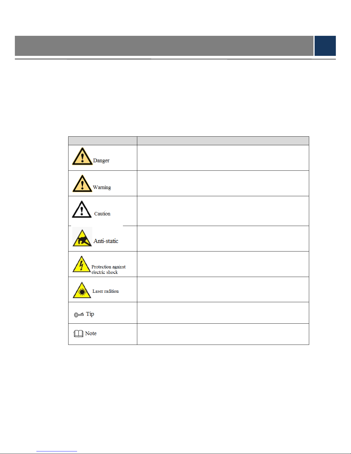
Symbol Definition
The following symbols may appear in the document. Please refer to the table below for the
respective definition.
Symbol
Note
It indicates a potentially hazardous situation which, if not avoided,
could result in death or serious injury.
It indicates a moderate or low level of potential danger which, if not
avoided, could result in minor or moderate injury.
It indicates a potential risk that, if ignored, could result in damage
to device, loss of data, degraded performance, or unpredictable
results.
It means electrostatic-sensitive device.
It means high-voltage danger.
It means intensive laser radiation.
It means that it can help you to solve some problems or save your
time.
It means the additional information, which is the emphasis and
supplement of the main body.
Page 7

VI
Important Safeguards and Warnings
The following description is the correct application method of the device. Please read the
manual carefully before use, in order to prevent danger and property loss. Strictly conform to
the manual during application and keep it properly after reading.
Operating Requirement
Please don’t place and install the device in an area exposed to direct sunlight or near heat
generating device.
Please don’t install the device in a humid, dusty or fuliginous area.
Please keep its horizontal installation, or install it at stable places, and prevent it from
falling.
Please don’t drip or splash liquids onto the device; don’t put on the device anything filled
with liquids, in order to prevent liquids from flowing into the device.
Please install the device at well-ventilated places; don’t block its ventilation opening.
Use the device only within rated input and output range.
Please don’t dismantle the device arbitrarily.
Please transport, use and store the device within allowed humidity and temperature range.
This device has been tested and found to comply with the limits for a Class A digital device,
pursuant to Part 15 of the FCC Rules and EMC Directive 2014/30/EU. Operation of this
device in a residential area is likely to cause harmful interference, in which case the user
will be required to correct the interference at his own expense.
Power Requirement
Please make sure to use batteries according to requirements; otherwise, it may result in
fire, explosion or burning risks of batteries!
To replace batteries, only the same type of batteries can be used!
The product shall use electric wires (power wires) recommended by this area, which shall
be used within its rated specification!
Please make sure to use standard power adapter matched with this device. Otherwise, the
user shall undertake resulting personnel injuries or device damages.
Please use power supply that meets SELV (safety extra low voltage) requirements, and
supply power with rated voltage that conforms to Limited Power Source in IEC60950-1. For
specific power supply requirements, please refer to device labels.
Products with category I structure shall be connected to grid power output socket, which is
equipped with protective grounding.
Appliance coupler is a disconnecting device. During normal use, please keep an angle that
facilitates operation.
Page 8

VII
Table of Contents
Legal Statement ..................................................................................................................................................... I
Cybersecurity Recommendations ................................................................................................................... II
Preface .................................................................................................................................................................... V
Important Safeguards and Warnings ............................................................................................................. VI
1 Appearance and Keys of Internet Keyboard............................................................................................ 1
1.1 Product Appearance ................................................................................................................................. 1
1.2 Key Module ................................................................................................................................................ 2
1.3 Port Introduction ........................................................................................................................................ 3
1.3.1 Rear Panel Ports ........................................................................................................................... 3
1.3.2 Side Panel Port .............................................................................................................................. 4
2 Start and Shutdown .......................................................................................................................................... 5
2.1 Start ............................................................................................................................................................. 5
2.2 Shutdown ................................................................................................................................................... 5
3 Quick Configuration .......................................................................................................................................... 6
3.1 Login Interface ........................................................................................................................................... 6
3.2 Main Interface ............................................................................................................................................ 6
3.3 Settings Interface ...................................................................................................................................... 7
3.4 Network Settings ....................................................................................................................................... 8
3.4.1 Wired Network ............................................................................................................................... 8
3.4.2 Wi-Fi ................................................................................................................................................ 9
3.5 Add Device ................................................................................................................................................11
3.5.1 Enter Device Management Interface.........................................................................................11
3.5.2 Manual Add ...................................................................................................................................11
3.5.3 Auto Search.................................................................................................................................. 12
4 Preview ............................................................................................................................................................... 14
4.1 Enter Preview Interface .......................................................................................................................... 14
4.2 Icons of Preview Interface ..................................................................................................................... 14
4.3 Video on Wall ........................................................................................................................................... 15
4.4 PTZ Control .............................................................................................................................................. 16
4.5 Snapshot .................................................................................................................................................. 17
4.6 Recording ................................................................................................................................................. 17
4.7 Snapshot and Recording Settings ........................................................................................................ 17
5 TV Wall ................................................................................................................................................................ 19
5.1 Add TV Wall through Matrix WEB Client ............................................................................................. 19
5.1.1 Enter Matrix WEB Login Interface ............................................................................................ 19
5.1.2 Add Network Signal .................................................................................................................... 20
5.1.3 Signal Group ................................................................................................................................ 20
5.1.4 Add TV Wall.................................................................................................................................. 21
5.2 Add TV Wall through Decoder WEB Client ......................................................................................... 21
5.2.1 Enter Decoder WEB Login Interface ........................................................................................ 22
5.2.2 Add Remote Device .................................................................................................................... 22
Page 9

VIII
5.2.3 Edit Decoder TV Wall ................................................................................................................. 23
5.3 Add Device ............................................................................................................................................... 23
5.4 Video on Wall ........................................................................................................................................... 23
5.5 Icons of TV Wall Interface ...................................................................................................................... 24
5.6 PTZ Control .............................................................................................................................................. 25
5.7 Add Task ................................................................................................................................................... 25
5.8 Configure TV Wall ................................................................................................................................... 26
6 Platform .............................................................................................................................................................. 29
7 PTZ Control ....................................................................................................................................................... 30
8 Settings .............................................................................................................................................................. 34
8.1 Device Management ............................................................................................................................... 34
8.1.1 Add Device ................................................................................................................................... 34
8.1.2 Input Channel .............................................................................................................................. 34
8.2 General Settings ..................................................................................................................................... 35
8.2.1 Wired Network ............................................................................................................................. 35
8.2.2 Wi-Fi .............................................................................................................................................. 35
8.2.3 Bluetooth ...................................................................................................................................... 35
8.2.4 Serial Port ..................................................................................................................................... 35
8.2.5 General ......................................................................................................................................... 36
8.2.6 Hardware ...................................................................................................................................... 37
8.3 Account ..................................................................................................................................................... 38
8.4 System ...................................................................................................................................................... 39
8.4.1 Version Upgrade .......................................................................................................................... 39
8.4.2 Configuration ................................................................................................................................ 39
9 Playback ............................................................................................................................................................. 41
10 Extension ......................................................................................................................................................... 43
Appendix 1 Technical Parameters .................................................................................................................. 44
Page 10
1
1 Appearance and Keys of Internet Keyboard
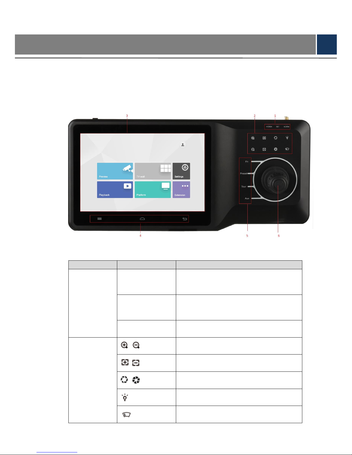
1.1 Product Appearance
Appearance of internet keyboard is shown in Figure 1-1. Please refer to Table 1-1 for details.
Figure 1-1
No.
Icon
Function
1
Power
Working power indicator light.
Green light turns on when working power of
internet keyboard is normal.
Network
Network indicator light.
Green light turns on when the keyboard is
connected with network normally.
Alarm
Alarm indicator light.
Red light turns on in case of alarms.
2
/
Zoom in/zoom out PTZ lens.
/
Increase/decrease the focus of PTZ lens.
/
Increase/decrease the aperture of PTZ lens.
Shortcut key to control speed dome light.
Shortcut key to control speed dome wiper.
Page 11
2
No.
Icon
Function
3 - Touch screen, showing keyboard screen menu.
4
Navigation bar.
Homepage.
Return.
5
Fn
Function key. It is line scanning by default.
Preset
PTZ control, preset point.
Tour
PTZ control, tour between points.
Aux
Auxiliary key. It is pattern by default.
6
-
Remote control lever, auxiliary menu and
function operation.
Table 1-1
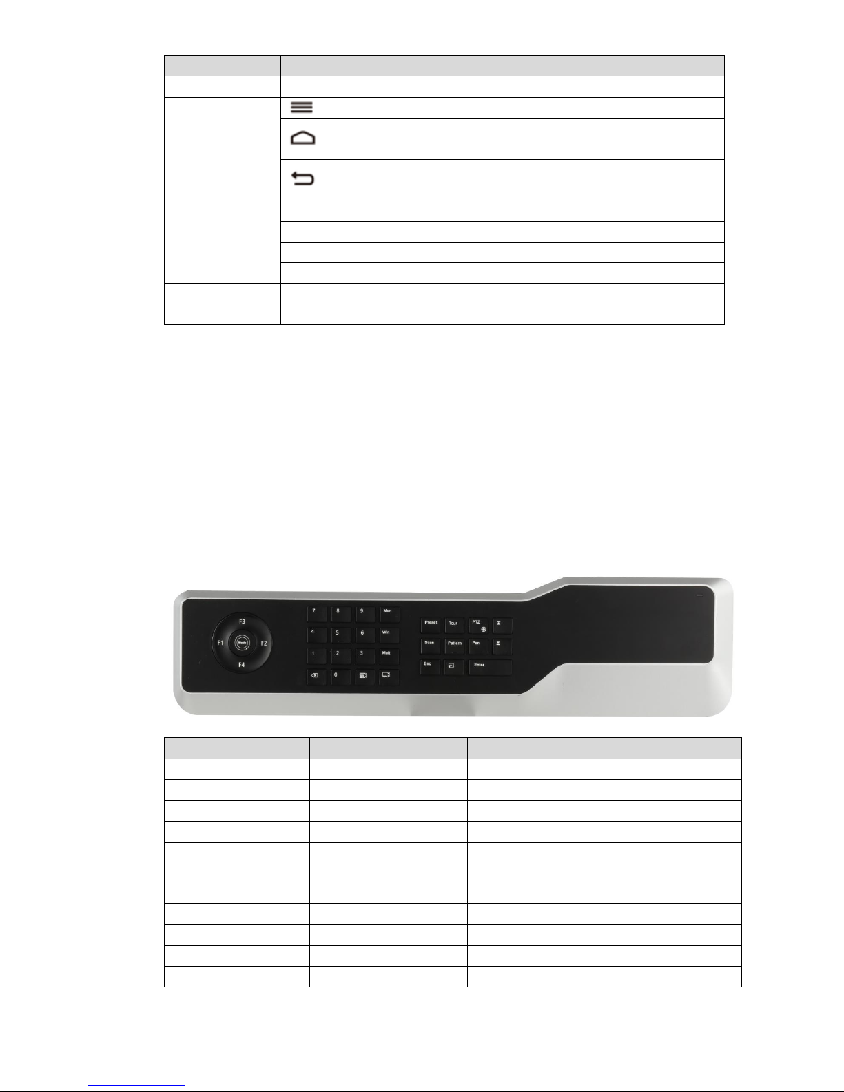
1.2 Key Module
After key module is connected with internet keyboard through USB or Bluetooth successfully,
green light at the upper right corner will be on for 10s and then turn off. Schematic diagram of
key module is shown in Figure 1-2. Please refer to Table 1-2 for details.
When key module is connected with internet keyboard through Bluetooth, please turn on main
switch at the side of key module. In case of Bluetooth connection, default WI-FI network name
is “KEYBOARD”.
Figure 1-2
Key
Example
Function
F1
Press F1
Reserved.
F2
Press F2
Reserved.
F3
Press F3
Reserved.
F4
Press F4
Reserved.
Mode
Operation mode switch.
It is operation mode at
present.
Reserved.
0~9
Number 0~9
-
Screen
123+screen
Reserved.
Window
3+window
Focus on the 3rd window of present screen.
Split
4+split
Divide present screen into 4 splits.
Page 12
3
Key
Example
Function
Press
Delete 1 digit from number buffer zone.
The icon is similar to squares.
(Camera group)
123+
Reserved.
(Camera)
567+
Drag no. 567 camera into present window.
0+camera means to turn off present video
source.
Preset
2+preset
Call no. 2 preset point.
Tour
5+tour
Call no. 5 tour.
PTZ
-
In case of USB power supply, long press it
to turn on and off the backlight.
Scan
3+scan
Call no. 3 scan.
Pattern
4+pattern
Call no. 4 pattern.
Rotate
Press
Press it once to start rotation, and press it
again to stop rotation.
Exit
-
Reserved.
Confirm
-
Snapshot function under preview module.
(Switch) previous
channel
KEY_ previous channel
Present focus window channel reduces 1.
The icon is similar to squares.
(Next channel)
KEY_ next channel
Present focus window channel adds 1. The
icon is similar to squares.
Playback
Reserved.
Table 1-2
1.3 Port Introduction
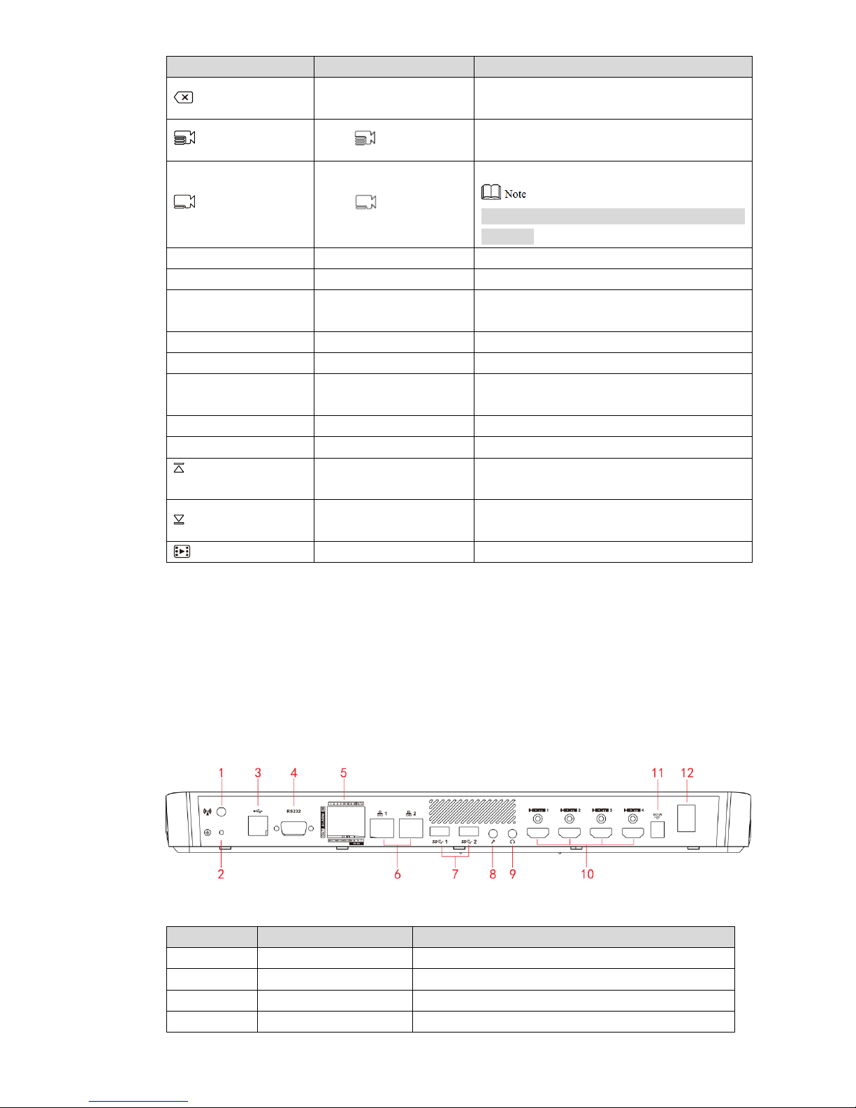
1.3.1 Rear Panel Ports
Rear panel ports are shown in Figure 1-3. Please refer to Table 1-3 for details.
Figure 1-3
No.
Name
Function
1
WI-FI port
Connect Wi-Fi antenna.
2
Grounding stud
Grounding.
3
USB2.0
Connect mouse and USB.
4
RS232
Connect serial port.
Page 13
4
No.
Name
Function
5
Alarm input/output port
Please refer to Table 1-4 for details.
6
Network port
Connect the network.
7
USB3.0
Connect mouse and USB.
8
Microphone
Connect microphone.
9
Earphone
Connect earphone.
10
HDMI1~HDMI4
Connect devices with HDMI port, such as display
screen.
11
Power port
Connect power cord to supply power.
12
Power on-off key
Turn on and off the power supply.
Table 1-3
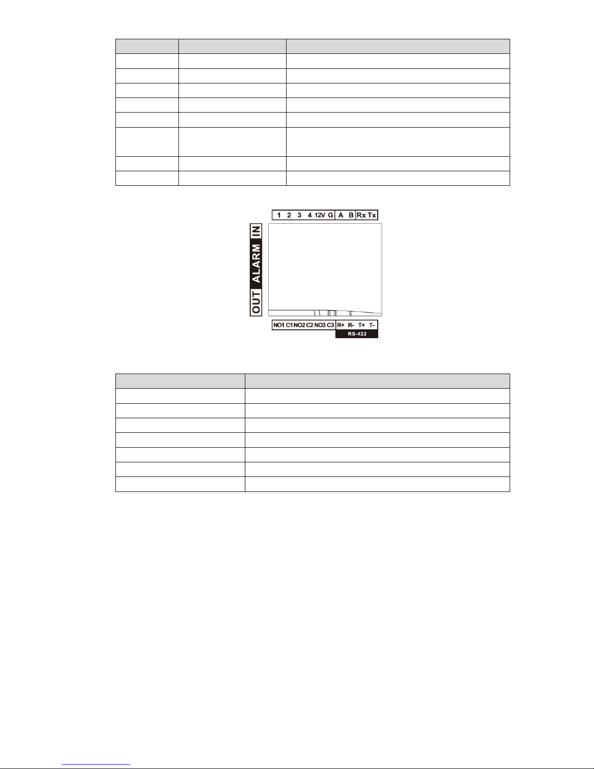
Figure 1-4
No.
Name
1~4
Alarm input port.
12V
DC 12V 1A power.
G
Grounding.
A, B
Connect PTZ.
Rx, Tx
RS-232 receiving and sending port.
NO1C1, NO2C2, NO3C3
3 groups of alarm output port.
R+, R-, T+, T-
RS-422 port.
Table 1-4
1.3.2 Side Panel Port
There are three keys on the side panel, including mute key, volume up key and volume down
key.
Page 14

5
2 Start and Shutdown
2.1 Start
Connect the power in accessories, turn on power on-off key, and start the internet keyboard.
The system displays login interface after it is started successfully. Its interface can be operated
with touch screen and external mouse.
2.2 Shutdown
Step 1 Shutdown.
Method 1: Click at the upper right corner of main interface, select “Shutdown”
and exit the system.
Method 2: Press power on-off key on the rear panel.
Step 2 After exiting the system, unplug the power and turn off the device.
Page 15
6
3 Quick Configuration
3.1 Login Interface
After starting, the system enters login interface.
Step 1 Enter password. Default password of the system is “admin”.
Step 2 Click “Login”.
After successful login, the system enters main interface.
Please modify admin password timely after login.
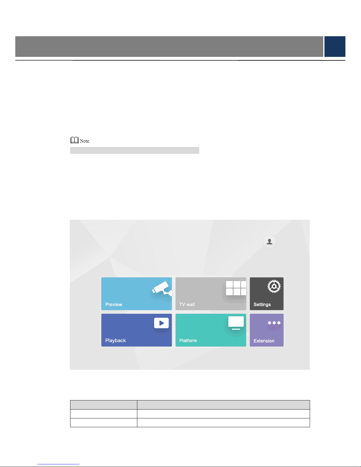
3.2 Main Interface
Main interface consists of preview, TV wall, playback, platform, settings and extension, as
shown in Figure 3-1.
Figure 3-1
Please refer to Table 3-1 for details.
Name
Description
Preview
Preview local devices and corresponding operations.
TV wall
Control decoder/matrix/TV wall.
Page 16
7
Name
Description
Playback
Play back videos in local recording device or USB disk.
Platform
After connecting with the platform, internet keyboard is able to
control devices on the platform.
Settings
There are four modules, including device, general, account and
system.
Extension
Control the devices with direct physical connection with internet
keyboard. At present, it only supports to control speed dome with
485 port.
Table 3-1
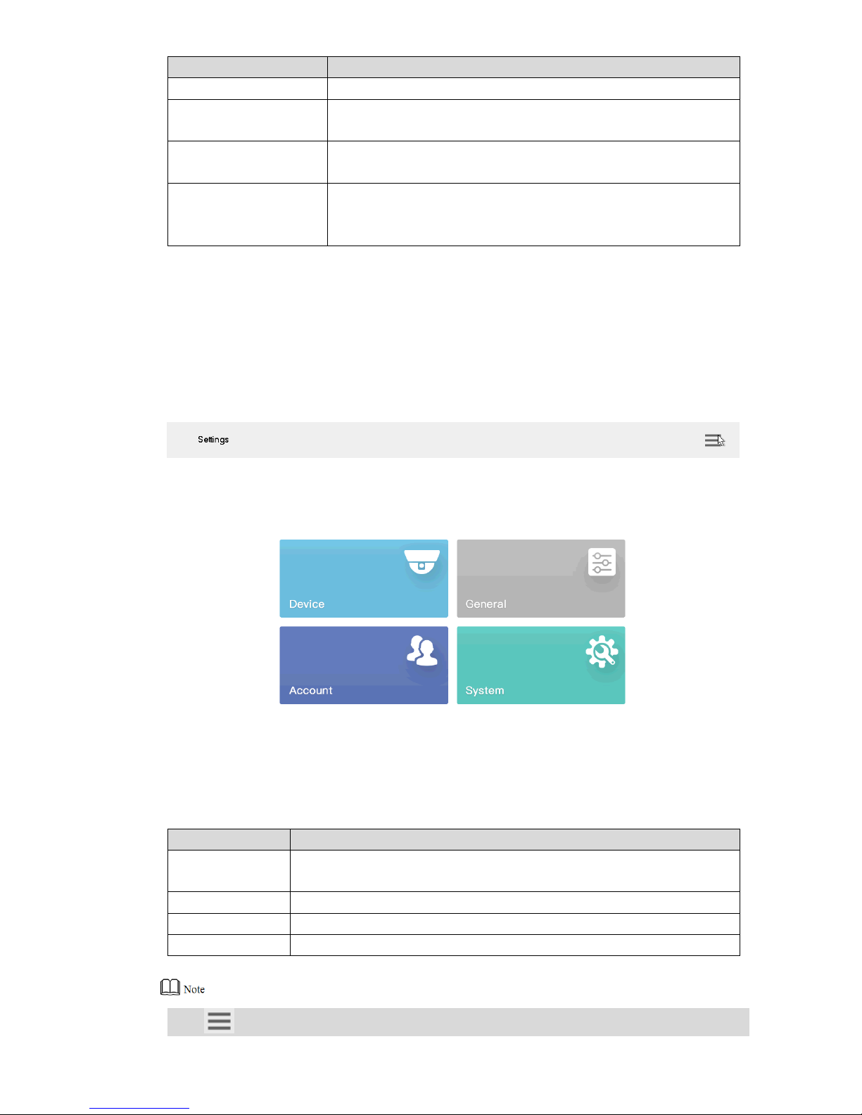
3.3 Settings Interface
At the main interface, click “Settings” to enter “Settings” interface, as shown in Figure 3-2.
Please refer to Table 3-2 for functional descriptions.
Figure 3-2
Name
Description
Device
Add, modify and delete devices; view input channel and modify input
channel no. and so on.
General
Set network, Bluetooth, serial port, date and time.
Account
Display account and modify user password.
System
View program version and upgrade.
Table 3-2
Click at the upper right corner, and a navigation bar appears in the page. With navigation
Page 17

8
bar, quickly return to preview, device, settings, playback, extension and homepage.
3.4 Network Settings
It includes wired network and Wi-Fi settings.
3.4.1 Wired Network
Configure IP address and DNS server of internet keyboard, so as to connect with other devices
in the networking.
Precondition
Before setting network parameters, please ensure that the internet keyboard has connected
network correctly.
Step 1 At “Settings” interface, click “General”. The system displays “Network” interface, as
shown in Figure 3-3.
Figure 3-3
Step 2 Set the parameters. Please refer to Table 3-3 for details.
Page 18

9
Parameter
Description
Net mode
It includes multi-address, fault tolerance and load balance.
Multi-address: two Ethernet cards are used independently. During
network status detection, if one Ethernet card is disconnected,
network is deemed to be disconnected.
Fault tolerance: two Ethernet cards use one IP address. Only one
Ethernet card works under normal conditions; if the working
Ethernet card breaks down, the other Ethernet card starts to work
automatically, so as to ensure smooth network. During network
status detection, network is deemed to be disconnected only
when both Ethernet cards are disconnected. Both Ethernet cards
shall be in the same LAN.
Load balance: two Ethernet cards use one IP address and work
together to undertake network load. Their network throughput is
basically the same. If one breaks down, the other one still works
normally. During network status detection, network is deemed to
be disconnected only when both Ethernet cards are
disconnected. Both Ethernet cards shall be in the same LAN.
Default card
When “Net Mode” is set to be “Fault Tolerance” or “Load Balance” and
multiple Ethernet cards are bonded, one Ethernet card can be
designated to be default working Ethernet card.
TCP port
It is usually default value.
IP version
It is IPv4 address format by default, which shall not be modified.
Ethernet card
Select Ethernet card.
IP address
Enter numbers to modify IP address, set corresponding “Subnet
Mask” and “Gateway”. Default IP address of Internet keyboard is
“192.168.1.108”.
Subnet mask
Gateway
Preferred DNS
IP address of DNS server.
Alternate DNS
IP address of alternate DNS server.
Table 3-3
Step 3 Click “Save”.
3.4.2 Wi-Fi
Automatic Search for Wi-Fi
Click to enable WI-FI function. The system will search Wi-Fi automatically and display
results as shown in Figure 3-4. Click to update the search.
Page 19

10
Figure 3-4
Wi-Fi Connection
Step 1 Double click Wi-Fi name or signal strength. “Wi-Fi Connection” dialog box will pop out,
as shown in Figure 3-5.
Step 2 Enter correct password and click “Connect”.
In case of successful connection, the connected “Wi-Fi Name” and “Connected” will be
displayed at the upper left corner.
Figure 3-5
Disconnect Wi-Fi
Click on the right of “Connected” Wi-Fi and click “Disconnect” in the popped out dialog
box.
Page 20

11
3.5 Add Device
It includes manual adding and auto search.
3.5.1 Enter Device Management Interface
In “Settings” interface, click “Device Manage” to enter the interface, as shown in Figure 3-6.
Figure 3-6
3.5.2 Manual Add
Step 1 Enter “Device Manage” interface and click . The system pops out “Manual
Add” dialog box, as shown in Figure 3-7.
Page 21

12
Figure 3-7
Step 2 Set the parameters. Please refer to Table 3-4.
Parameter
Description
Protocol
Select protocol type. It only supports “Private” at present.
Start IP and End IP
Enter start IP and end IP when one IP segment is added.
Enter start IP when one IP is added.
Port
Enter port number. It is usually default value.
Username and password
Enter username and password.
Channel
Enter channel quantity. means that it is opened, while
means that it is closed.
For example, total channel quantity of the device is 48.
However, if you want to add 1st channel ~16th channel, set the
channel quantity.
Table 3-4
Step 3 Click “OK”.
3.5.3 Auto Search
Step 1 Enter “Device Manage” interface and click . The system pops out dialog box of auto
search, as shown in Figure 3-8.
Page 22

13
Figure 3-8
Step 2 Enter IP segment and tick the check box.
Step 3 Click “Save”. Auto search results are shown as Figure 3-9.
Alternatively, click to view search results.
Figure 3-9
Page 23

14
4 Preview
Preview local devices, video on wall, PTZ control, snapshot and recording.
4.1 Enter Preview Interface
Click “Preview ” at main interface to enter “Preview” interface, as shown in Figure 4-1. There
are five modes, including VGA and HDMI1~HDMI4.
Figure 4-1
4.2 Icons of Preview Interface
Icon
Description
Icon
Description
Snapshot
Screenshot to USB disk
Manual recording
Snapshot and recording settings
Maximize and restore the window
Single split
4-split
9-split
16-split
Page 24

15
Icon
Description
Icon
Description
Custom split
PTZ
Select screen
Smart stream mode
Delete
-
-
Table 4-1
4.3 Video on Wall
Step 1 At “Preview” interface, select VGA or HDMI1~HDMI4 in pull-down dialog box.
Step 2 Select video source in the right, drag it onto TV wall or double click the video source.
Quick Video on Wall (Optional)
Click , and a dialog box will pop out, as shown in Figure 4-2. Enter “Number (such as 1)+
”, so no. 1 device will be on wall quickly.
Please refer to “8.1.2 Input Channel” to inquire “Number” in the input channel.
Figure 4-2
Quick Search for Added Device (Optional)
In the input box behind , enter keywords of the added device, so as to search the added
device.
Click the popped out language box, as shown in Figure 4-3. Press [Shift] key to switch the input
method.
Page 25

16
Figure 4-3
Maximize and Restore Window
Click to maximize and restore the window.
Single/4/9/16/Custom Split
Click , , , or respectively, representing single/4/9/16/custom split.
Clear Video Source
Step 1 Select a window.
Click , to select the focused window.
Click again and the icon turns to be , to select all windows within present
operating screen.
Step 2 Click .
Smart Stream Mode
Main stream goes on wall in case of single split.
Sub-stream goes on wall in case of 9-split and 16-split.
In case of 4-split, with HDMI1 and HDMI2 preview mode, main stream goes on wall. In
other preview modes, sub-stream goes on wall.
4.4 PTZ Control
Please refer to “7. PTZ Control” for details.
Page 26

17
4.5 Snapshot
At “Preview” interface, insert a USB disk into Internet keyboard, and click after checking
USB disk.
4.6 Recording
At “Preview” interface, insert a USB disk into Internet keyboard, and click after checking
USB disk.
4.7 Snapshot and Recording Settings
Step 1 At “Preview” interface, click . The system displays “Snap & Record” interface, as
shown in Figure 4-4.
Figure 4-4
Step 2 Insert a USB disk into Internet keyboard.
Step 3 Click “Check”. The system displays general storage disk name and device storage.
Step 4 Set the parameters. Please refer to Table 4-2 for details.
Page 27

18
Parameter
Description
Snap settings
It supports only 1 snapshot at present.
Resolution
Select resolution.
When video resolution﹥ the set resolution, snapshot image
adopts the set resolution.
When video resolution﹤ the set resolution, snapshot image
adopts actual video resolution.
USB storage
It is enabled by default.
Format
Click this button to format USB disk.
Path
Click this button to select snapshot storage path.
Table 4-2
Step 5 Click “OK”.
Page 28

19
5 TV Wall
Control decoder/matrix/TV wall.
Devices can be added only through WEB client. For details, please refer to “5.1 Add TV Wall
through Matrix WEB Client” and “5.2 Add TV Wall through Decoder WEB Client”.
There are two ways to add TV wall through WEB client:
Matrix WEB (support multiple TV walls)
Decoder WEB (only one TV wall)
TV walls can be added in TV wall configuration of keyboard. Please refer to “5.8 Configure TV
Wall” for details.
5.1 Add TV Wall through Matrix WEB Client
This part takes matrix WEB client as an example.
This part is operated at matrix WEB client.
For more specific configurations, please refer to matrix user’s manual.
This part also applies to large screen device.
5.1.1 Enter Matrix WEB Login Interface
Step 1 Enter IP address of matrix at address bar of the browser; press [Enter] key to enter
matrix login interface, as shown in Figure 5-1.
Figure 5-1
Step 2 Enter username and password. Default password is “admin”.
Step 3 Click “Login” to enter WEB interface.
Page 29

20
5.1.2 Add Network Signal
Search or add network signals manually.
Step 1 Select “Settings > Signal > Network Signal”. The system displays “Network Signal”
interface, as shown in Figure 5-2.
Figure 5-2
Step 2 Add network signals.
Click “Device Search” to show search results, select the needed device and click
“Add”.
Click “Manual Add” to set parameters in the popped out dialog box.
5.1.3 Signal Group
Select “Settings > Signal > Signal Group”. The system displays “Signal Group” interface, as
shown in Figure 5-3. Devices in the device list can be added to group list.
Page 30

21
Figure 5-3
5.1.4 Add TV Wall
Step 1 Select “Settings > Display > TV Wall> TV Wall Config”. The system displays “TV Wall
Config” interface, as shown in Figure 5-4.
Figure 5-4
Step 2 Click “Add TV Wall” to add it.
5.2 Add TV Wall through Decoder WEB Client
This part takes decoder WEB client as an example.
This part is operated at decoder WEB client.
Page 31

22
For more specific configurations, please refer to decoder user’s manual.
5.2.1 Enter Decoder WEB Login Interface
Step 1 Enter IP address of decoder at address bar of the browser; press [Enter] key to enter
decoder login interface, as shown in Figure 5-5.
Figure 5-5
Step 2 Enter username and password. Default password is “admin”.
Step 3 Click “Login” to enter WEB interface.
5.2.2 Add Remote Device
Search or add network signals manually.
Step 1 Select “Settings > Remote Device”. The system displays “Remote Device” interface,
as shown in Figure 5-6.
Figure 5-6
Step 2 Add remote device.
Click “Device Search” to show search results, select the needed device and click
Page 32

23
“Add”.
Click “Manual Add” to set parameters in the popped out dialog box.
5.2.3 Edit Decoder TV Wall
Click merged screen to edit TV wall.
5.3 Add Device
Add TV wall, matrix and decoder device. Please refer to “3.5 Add Device” for details.
5.4 Video on Wall
Step 1 At main interface, click “TV Wall” to enter “TV Wall” interface.
Step 2 In the pull-down list, select TV wall, as shown in Figure 5-7.
Figure 5-7
Step 3 Click one screen in Figure 5-7, such as MON:169.
Step 4 Split the screen. For example, click to realize 4-split.
Step 5 Drag video source in the right onto large screen. The system displays relevant info, as
shown in Figure 5-8.
Page 33

24
Figure 5-8
Switch Main and Sub-stream
Click to switch main and sub-stream. M represents main stream, while S represents
sub-stream.
Clear Screen
Click to clear screen.
For other operations of TV wall, please refer to “4.3 Video on Wall”.
5.5 Icons of TV Wall Interface
Please refer to Table 5-1 for introductions to icons.
Icon
Description
Icon
Description
Refresh
Config TV wall
Reserved
Clear screen
Return
Maximize and restore the window
Single split
4-split
Page 34

25
Icon
Description
Icon
Description
9-split
16-split
Custom split
PTZ
Select screen
Switch main and sub-stream. M
represents main stream, while S
represents sub-stream.
Delete
-
-
Table 5-1
5.6 PTZ Control
Please refer to “7 PTZ Control”.
5.7 Add Task
Frequently-used operations can be saved as tasks, in order to call them quickly.
Step 1 At “TV Wall” interface, carry out a series of operations according to actual needs. For
example, split the screen into 16 parts.
Step 2 Click . “Add Task” dialog box will pop out, as shown in Figure 5-9.
Figure 5-9
Step 3 Enter task name.
Step 4 Click “OK”.
Page 35

26
5.8 Configure TV Wall
At “TV Wall” interface, click to enter “TV Wall Config” interface, as shown in Figure 5-10.
Figure 5-10
Enable TV Wall
Click to enable TV Wall. Then, “TV Wall” pull-down list in Figure 5-7 will display this TV
wall.
If decoding channel of this TV wall is bonded to other TV walls, other TV walls will be disabled.
New TV Wall
Step 1 Click , and the system will pop out a dialog box of “New TV Wall”, as shown in
Figure 5-11.
Page 36

27
Figure 5-11
Step 2 Enter the name, select line no. and column no., and then click “OK”.
Step 3 Drag decoding channels in the right into the screen, so as to bond corresponding
relations.
Step 4 (Optional) Select two or more screens, click “Merge” to merge them into one screen.
Step 5 Click .
Delete TV Wall
Click to delete TV wall.
Cancel Merged Screen
Select a merged screen and click “Cancel”.
Edit TV Wall
Click “Edit” and the system will pop out a dialog box of “New TV Wall”, as shown in Figure 5-12.
Page 37

28
Figure 5-12
Return to TV Wall Interface
Click “Return” to return to TV wall interface.
Exit TV Wall Interface
Click to exit TV wall interface.
Page 38

29
6 Platform
The internet keyboard can connect with a platform, and thus control devices that are added to
the platform.
Page 39

30
7 PTZ Control
Precondition: speed dome owns PTZ function.
Click in “Platform” interface, so PTZ control interface appears in the right, as shown in
Figure 7-1.
Figure 7-1
Parameter
Description
Step type
It consists of fixed step and variable step.
By selecting “Fixed”, the step remains unchanged when PTZ
turns; it is always the set step value.
By selecting “Variable”, the step changes with the tilt of joystick.
The larger tilt angle represents quicker turning speed.
8 direction keys
Control turning direction of SD lens.
Zoom
Set the zoom increase/decrease of PTZ lens.
Focus
Set the focus increase/decrease of PTZ lens.
Iris
Set the iris increase/decrease of PTZ lens.
Call
Call the preset point, scan, tour and pattern.
Settings
PTZ operation settings, including the preset point, scan, tour and
pattern.
SD menu
Open and close SD menu.
Auxiliary function
Lighting and wiper function.
Table 7-1
Page 40

31
Use the joystick to control 8 directions of PTZ.
Call
Enter a number in the input box, such as “1”. Click “Preset” to call the preset point 1.
It will be called successfully under the precondition that preset point 1 exists. Call methods of
scan, tour and pattern are the same as that of preset point.
Figure 7-2
Settings
Settings of Preset Point
Step 1 Turn the camera to required position with the joystick or direction button.
Step 2 Select “Preset”.
Step 3 Enter a preset point value in “Preset” input box, such as “1”.
Step 4 Click “Settings”. Preset point 1 is set successfully.
Settings of Tour
Step 1 Enter tour route value in “Tour No.” input box.
Step 2 Enter a preset point value in “Preset” input box and click “Add Preset” to add a preset
point to the tour route.
Multiple preset points can be added.
Click “Del Preset” to delete the preset point from this tour route. Repeat the
operation to delete multiple preset points from this tour route. Preset points cannot
be deleted in some protocols.
Click “Del Tour” to delete the present tour route.
Page 41

32
Settings of Pattern
Step 1 Enter pattern no. in the dialog box of pattern no..
Step 2 Click “Start Pattern” to carry out operations of zoom, focus, iris or direction.
Step 3 Click “Stop Pattern” to complete the settings of one pattern route.
Settings of Scan
Turn the camera to left margin with the joystick or direction button; click “Set Left” to determine
left margin position. Set the right margin position in the same way, so as to complete the
settings of scan route.
Figure 7-3
Page 42

33
SD Menu
Figure 7-4
Auxiliary Function
Figure 7-5
Auxiliary function includes single light, multi-light and wiper.
Light mode includes manual, SmartIR and zoom ratio first.
Light strength: light strength can be set.
Light angle: light angle can be set.
Page 43

34
8 Settings
It consists of four parts, namely, device, general, account and system.
8.1 Device Management
8.1.1 Add Device
Please refer to “3.5 Add Device”.
8.1.2 Input Channel
Display input no., channel no., name, device, IP address and protocol of all channels.
Meanwhile, modify input channel no..
At “Settings” interface, click “Device”, and then click “Input Channel” tab to enter “Input Channel”
interface, as shown in Figure 8-1.
Figure 8-1
Modify Input Channel No.
Click to modify input channel no. in the popped out dialog box.
Page 44

35
8.2 General Settings
8.2.1 Wired Network
Please refer to “3.4.1 Wired Network” for details.
8.2.2 Wi-Fi
Please refer to “3.4.2 Wi-Fi” for details.
8.2.3 Bluetooth
Default Bluetooth name of internet keyboard is “KEYBOARD”.
Step 1 At “General” interface, click “Bluetooth” tab to enter “Bluetooth” interface.
Step 2 Click to enable Bluetooth.
Step 3 Click to search nearby Bluetooth device.
Step 4 Double click the searched device and the system will display “Connecting”. After
several seconds, the system will display “Connected”, so it is connected successfully,
as shown in Figure 8-2.
Figure 8-2
8.2.4 Serial Port
Step 1 At “General” interface, click “Serial” tab to enter “Serial” interface, as shown in Figure
8-3.
Page 45

36
Figure 8-3
Step 2 Set the parameters. Please refer to Table 8-1 for details.
Parameter
Description
Address
In case of serial port control, identify devices according to the address.
Value ranges from 0 to 255.
Baud rate
Baud rate ranges from 1200 to 115200. There are 8 levels available.
Data bit
Select data bit, including 5, 6, 7 and 8.
Stop bit
Select stop bit, including 1 and 2.
Parity
Select parity, including none, odd, even, checkmark and null parity.
Table 8-1
Step 3 Click “OK”.
8.2.5 General
Set name, date and time etc. of internet keyboard.
Step 1 At “General” interface, click “General” tab to enter “General” interface, as shown in
Figure 8-4.
Page 46

37
Figure 8-4
Step 2 Set the parameters. Please refer to Table 8-1 for details.
Parameter
Description
Name
Set internet keyboard name.
Language
Select language.
Date
Set date.
Time
Set time.
Format
Set time format, including 24-hour and 12-hour.
Separator
Set date separator, including “.”, “-” and “/”. When it takes effect, system
time is displayed as “2017.08.08”, “2016-08-08” and “2016/08/08”.
Table 8-2
Step 3 Click “Save”.
8.2.6 Hardware
Adjust volume, set the locking time of internet keyboard and screen off time.
Step 1 At “General” interface, click “Hardware” tab to enter “Hardware” interface, as shown in
Figure 8-5.
Page 47

38
Figure 8-5
Step 2 Set the parameters. Please refer to Table 8-2 for details.
Parameter
Description
Volume adjust
Adjust the volume.
Keyboard lock
After keyboard is locked, log in the device to enter it again.
Screen off
Screen off time can be max. 60 minutes.
Table 8-3
Step 3 Click “Save”.
8.3 Account
View details of current account.
Step 1 At main interface, click “Settings” to enter settings interface.
Step 2 Click “Account” to enter the account interface, as shown in Figure 8-6.
Figure 8-6
Step 3 Click to modify user’s password.
Page 48

39
8.4 System
8.4.1 Version Upgrade
Upgrade the device with USB disk.
Step 1 At “System” interface, click “Upgrade” tab to enter “Upgrade” interface, as shown in
Figure 8-7.
Figure 8-7
Step 2 Insert USB disk into the internet keyboard, and click “USB Check”.
Step 3 Click “Choose Files” to upgrade.
8.4.2 Configuration
Import or export system configurations.
Step 1 At “System” interface, click “Config” tab to enter “Config” interface, as shown in Figure
8-8.
Page 49

40
Figure 8-8
Step 2 Insert USB disk into the internet keyboard, and click “USB Check”. Detect all
connected USB and capacity.
Step 3 Import or export configurations.
Import config: import config info in USB disk into the internet keyboard.
Export config: export config info in the present keyboard to USB disk.
Click “Format” to format the USB disk.
Page 50

41
9 Playback
Play back existing records.
Step 1 At main interface, click “Playback” tab to enter “Playback” interface.
Step 2 Select target device and channel.
Step 3 Set the start time and end time.
Step 4 Click “Search”.
Display search results in the list, as shown in Figure 9-1.
Figure 9-1
Step 5 Select one search result and click “Playback”, as shown in Figure 9-2.
Page 51

42
Figure 9-2
Step 6 Click to download the record to USB disk. Records in USB disk can be played
back.
Page 52

43
10 Extension
Control the devices with direct physical connection with internet keyboard. At present, it only
supports to control speed dome with 485 port.
Step 1 At main interface, click “Extension” to enter “Analog Keyboard” interface, as shown in
Figure 10-1.
Figure 10-1
Step 2 Set the parameters. Please refer to Table 10-1 for details.
Parameter
Description
Connection mode
Set the connection mode, which only supports RS485 at present.
Device type
Enter device type.
Address
Enter device address.
Protocol
Select the protocol, including SD1, PELCOD and PELCOP.
Baud rate
Select baud rate.
Data bit
It includes 5, 6, 7 and 8.
Parity
It includes null, odd and even parity.
Stop bit
It includes 1, 1.5 and 2.
Table 10-1
Step 3 Click “OK”.
Open PTZ control interface to carry out PTZ control.
Page 53

44
Appendix 1 Technical Parameters
Parameter
Description
LCD screen
10.1 inch TFT LCD screen, 1280×800 resolution
Touch screen
10.1 inch capacitance screen, 1280×800 resolution
Joystick
4D joystick
Video port
1 LCD screen and 4 HDMI ports. There are 5 output ports in total.
Local decoding
[Stream type] Support H.265, H.264, H264H, H264B, MJPEG, SVAC,
SmartH.264 and non-standard stream.
[Decoding performance] Support hardware decoding, 1200W/4K/1080P
[Split performance] At present, single screen supports max. 16-split, so 5
screens support 80-split in total.
Audio input
1 audio input, 3.5mm stereo, support voice intercom function.
Audio output
1 audio output, 3.5mm stereo
Loudspeaker
1 loudspeaker to play audios.
Network port
Two 100M/1000M self-adaptive Ethernet ports
Wi-Fi
Support
USB port
4 USB ports, including 2 USB2.0 ports and 2 USB3.0 ports
RS485
1, as PTZ control port
RS232
2, as ordinary serial port (debugging), to control the recorder and other
devices
RS422
1
Power input
DC 12V 4A
Operating
temperature
-10℃~55℃
Operating humidity
10%~95% 86kPa~106kPa
Dimension
Host: 425mm×194mm×59mm (length × width× height, excluding joystick
/ antenna)
Keyboard: 421mm×105mm×26mm (length × width× height)
Weight
3.73kg
Appendix Table 1-1 Technical Parameters
 Loading...