

Page 1

Dahua Navigator X820 User’s Manual
V 1.0.0
ZHEJIANG DAHUA VISION TECHNOLOGY CO., LTD.
Page 2

1
Table of Contents
1 Product Introduction ........................................................................................................................... 10
1.1 Overview ...................................................................................................................................... 10
1.2 Features ....................................................................................................................................... 10
2 Structures ............................................................................................................................................ 12
2.1 Aircraft .......................................................................................................................................... 12
2.1.1 Product Dimensions ............................................................................................................ 12
2.1.2 Structural Component ......................................................................................................... 13
2.2 Airborne Equipment ................................................................................................................... 15
2.2.1 Visible Light PTZ Camera .................................................................................................. 15
2.2.2 IR PTZ Camera .................................................................................................................... 19
2.3 Remote Control .......................................................................................................................... 21
2.3.1 Dimensions ........................................................................................................................... 22
2.3.2 Structural Component ......................................................................................................... 23
2.3.3 Buttons .................................................................................................................................. 27
2.3.4 Operation Interface ............................................................................................................. 29
2.4 Ground Control Station (GCS) ................................................................................................. 35
2.4.1 Product Dimensions ............................................................................................................ 35
2.4.2 Structural Component ......................................................................................................... 36
2.4.3 Operation GUI ...................................................................................................................... 37
3 Flight Preparation ............................................................................................................................... 45
3.1 Unpack ......................................................................................................................................... 45
3.2 Check Remaining Battery ......................................................................................................... 45
3.2.1 Aircraft ................................................................................................................................... 45
3.2.2 Remote Control .................................................................................................................... 46
3.2.3 Ground Station Battery Check ........................................................................................... 47
3.3 Charging ...................................................................................................................................... 48
3.3.1 Aircraft Battery Charging .................................................................................................... 48
3.3.2 Remote Control Charging .................................................................................................. 49
3.3.3 Ground Station Charging.................................................................................................... 49
3.4 Prepare Airborne Equipment .................................................................................................... 50
3.4.1 Demount PTZ Camera........................................................................................................ 50
3.4.2 Install PTZ Camera ............................................................................................................. 51
3.5 Prepare Aircraft .......................................................................................................................... 51
3.5.1 Unfold Aircraft Arm .............................................................................................................. 51
3.5.2 Open Antenna ...................................................................................................................... 52
3.5.3 Install Aircraft Battery .......................................................................................................... 52
3.6 Prepare Ground Station ............................................................................................................ 53
3.6.1 Set up Antenna .................................................................................................................... 53
3.6.2 Enable Ground Station Power ........................................................................................... 54
3.7 Prepare Remote Control ........................................................................................................... 55
3.7.1 Install SIM Card, SD Card .................................................................................................. 55
3.7.2 Open Antenna ...................................................................................................................... 56
3.7.3 Enable Remote Control Power .......................................................................................... 56
Page 3

2
3.7.4 Confirm Remote Control Mode .......................................................................................... 57
3.8 Enable Aircraft Power ................................................................................................................ 57
3.9 Check and Debugging ............................................................................................................... 58
3.9.1 Aircraft Diagnosis ................................................................................................................ 58
3.9.2 Remote Control Calibration................................................................................................ 59
3.9.3 Accelerometer Calibration .................................................................................................. 60
3.9.4 Initialization Failure ............................................................................................................. 60
3.9.5 Geomagnetic Abnormity ..................................................................................................... 60
3.9.6 GPS Satellites Insufficient .................................................................................................. 62
3.10 Install Propellers ......................................................................................................................... 62
4 Enable Flight ....................................................................................................................................... 64
4.1 Flight Mode .................................................................................................................................. 64
4.2 Manual Mode .............................................................................................................................. 65
4.2.1 Flow Introduction of Manual Flight .................................................................................... 65
4.2.2 Unlock Flight Control ........................................................................................................... 65
4.2.3 Manual Takeoff .................................................................................................................... 66
4.2.4 Manual Flight Control .......................................................................................................... 67
4.2.5 Manual RTH and Landing .................................................................................................. 68
4.2.6 Manual Lock ......................................................................................................................... 69
4.3 Intelligent Mode .......................................................................................................................... 70
4.3.1 Flight Route .......................................................................................................................... 70
4.3.2 Intelligent Flight Mode ......................................................................................................... 71
4.3.3 Intelligent Lock Mode .......................................................................................................... 76
4.4 Intelligent Protection Mechanism ............................................................................................. 77
4.4.1 Low Battery........................................................................................................................... 77
4.4.2 Out of Control ....................................................................................................................... 77
4.4.3 Electronic Fence .................................................................................................................. 77
4.4.4 Remote Control Parameter Setting................................................................................... 80
5 End Flight ............................................................................................................................................ 85
5.1 Turn off Power ............................................................................................................................ 85
5.2 Remove Aircraft Battery ............................................................................................................ 86
5.3 Dismantle Airborne Equipment ................................................................................................ 87
5.4 Fold Aircraft ................................................................................................................................. 88
5.5 Dismantle Image Transmission Antenna ................................................................................ 89
5.6 Copy Camera SD Card Video .................................................................................................. 89
5.7 Remove Other Components ..................................................................................................... 90
6 Upgrade ............................................................................................................................................... 91
6.1 Aircraft Firmware Update .......................................................................................................... 91
6.2 Remote Control Update ............................................................................................................. 91
6.2.1 APP Update .......................................................................................................................... 91
6.2.2 Remote Control Offline Map Download and Update ...................................................... 92
6.3 Ground Station Update .............................................................................................................. 94
6.3.1 Ground Station Software Update ...................................................................................... 94
6.3.2 Ground Station Map Update .............................................................................................. 94
6.3.3 Ground Station Offline Map ................................................................................................ 94
7 Appendix Ⅰ Main Technical Parameters ...................................................................................... 98
Page 4

3
8 Appendix Ⅱ Aircraft Status Indicator ........................................................................................... 102
9 Appendix Ⅲ System Pairing .......................................................................................................... 104
10 Appendix Ⅳ FAQ ........................................................................................................................ 106
10.1 Aircraft FAQ and Its Solutions ................................................................................................ 106
10.2 Remote Control FAQ and Its Solutions ................................................................................. 106
10.3 Ground Station FAQ and Its Solutions .................................................................................. 106
10.4 Airborne Equipment FAQ and Its Solutions ......................................................................... 107
Page 5
4
Legal Statement
Copyrights
© 2017 Dahua Vision Technology. All rights reserved.
Any or full contents of the user’s manual cannot be copied, transmitted, distributed, partially or wholly,
by any means, without the prior written notice of Dahua Vision Technology (herein after “Dahua”).
Dahua or the third party may reserve the right of the product described in this user’s manual. Without
the prior written approval of the corresponding party, any person cannot (including but not limited to)
copy, distribute, amend, reverse compile, disassemble, engineering, rent, reverse engineer, reverse
compile or disassemble the software.
Trademark
, , are the trademarks or registered trademarks of the Dahua in various
jurisdictions.
Other trademarks and registered trademarks mentioned are the properties of their respective
owners.
Update and Modification
In order to enhance the product security and provide better user experience, Dahua may improve the
product via software auto update, but Dahua doesn't need to inform in advance and isn't liable to any
responsibility.
Dahua reserves the right to modify any information in this document at any time, the modified contents
will be added into the new version without prior announcement. There may be minor difference about
some product fucntions after it is updated.
Page 6
5
Preface
Document Overview
The document is to comprehensively introduce the product function features, structure parameters,
installation dismounting and flight guide etc.
Applied Model
X820
Application Objective
The main readers of the manual are terminal users.
Reading Guide
Chapter
No.
Chapter
Name
Main Content
1
Product
Overview
It is to introduce the function features and application scenarios of
the product.
2 Product
Component
It is comprehensively to introduce the main components of the
product.
It is recommended to read the chapter before use, which is to
understand the application methods of product structure and main
components.
3
Flight
Preparation
It is to introduce the complete flow of aircraft unlock before takeoff
in details.
It has to strictly conform to the installation debudding sequence of
the chapter, install each component and make initial debugging
before first use.
If it is not the first time to use the device, you can select the
installation content according to the dismounting situation last time,
but it has to be confirmed that all the components (unnecessary
steps excluded) listed in the chapter have been stably installed.
4
Enable
Flight
It is to introduce the complete flow of aircraft formal lauch and
landing in details.
It has to complete the preparation steps listed in the chapter 3.
It needs to confirm that all the inspection items including
environment and the device itself have conformed to flight
requirements before enabling flight.
Please operate by strictly conforming to the steps described in the
chapter, the operation sequence can't be reversed.
5
End Flight
It is to introduce the operation steps after aircraft landing in details.
Please operate by strictly conforming to the steps described in this
chapter, the operation sequence can't be reversed.
6
Upgrade
It is to introduce upgrade methods and attentions.
Page 7
6
7
Appendix 1
It is to introduce the technical parameters.
8
Appendix 2
It is to introduce the indicator definition of the aircraft.
9
Appendix 3
It is to introduce the matching method among the components.
10
Appendix 4
It is to list the problems and its solutions when using the product.
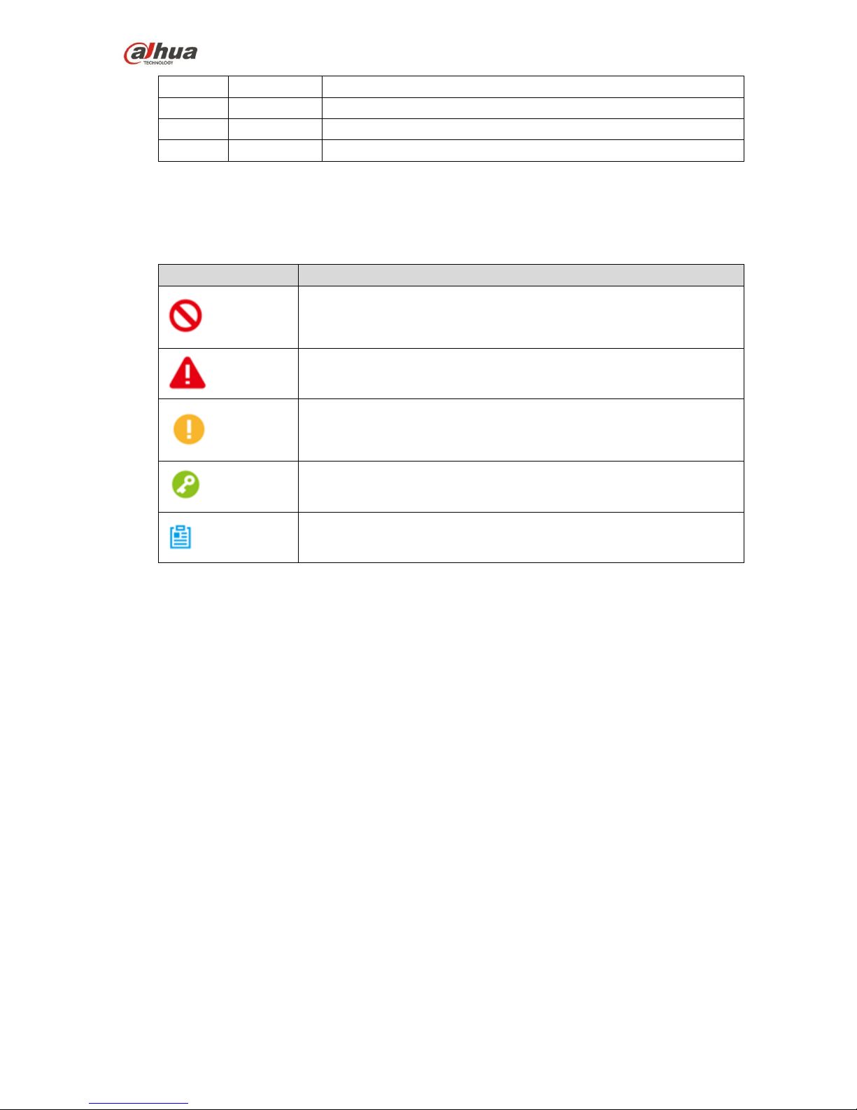
Symbol Definition
The following symbol may appear in the document, please refer to the table below for the respective
definition.
Symbol
Note
Danger
It means highly potential danger. It will cause severe injury or
casualties if it fails to avoid.
Warning
It means moderate or low potential danger. It may cause slight or
moderate injury if it fails to avoid.
Caution
It means potential risk. It may cause device damage, weaker
performace or other unpredictable consequences if it fails to avoid.
Tips
It means that it can help you to solve some problem or save your time.
Note
It means the additional information, which is the emphasis and
supplement of the main body.
Document Material
The product includes the following document materials, you can seach according to your requirements:
<Quick Start Guide>
It can be applied to the first flight. Please refer to <User Manual> for operation details when it is used for the
second time or it has to use some other advanced functions.
Check the paper material affiliated in the packaging or log in www.dahuatech.com and search X820 to
acquire more details.
<User Manal> (the document it is)
It comprehensively introduces the product function features, structure parameters, installation dismounting
and flight guide etc.
Log in www.dahuatech.com and search X820 to acquire more details.
Page 8
7
Important Safeguards and Warnings
The following description is the correct application method of the device. Please read the manually carefully
before use in order to prevent danger and property loss. It has to strictly conform to the manual during
application and keep it properly after reading.
Danger
Please fly the aircraft in the environment which meets flight conditions, keep away from no-fly zone.
Please do not get close to the rotating component, which is to prevent personal injury.
Warning
Please transport, use and store the product and all other components in the environment which satisfies
the requirements.
Please strictly conform to the flow operation described in the manual when dismantling the device,
please do not dismantle other components unprofessionally.
Caution
Please do not touch the lens of PTZ camera directly, you can use hair drier to remove the dust or dirt on
the lens surface.
Please operate the device by strictly conforming to the steps described in the chapter, the operation
sequence can't be reversed.
It needs to understand the local laws and regulations before using the aircraft. Please apply to local
authorities for flight permission if necessary.
Please select open wide environment outdoors for the first flight. It is to unlock the aircraft and take off
when the number of GPS satellites reaches more than 6.
Please make sure the device antenna has been properly installed before enabling the power of remote
control, ground station or aircraft, otherwise it may cause damage to internal module or make the control
distance shorter.
Flight Environment
Warning
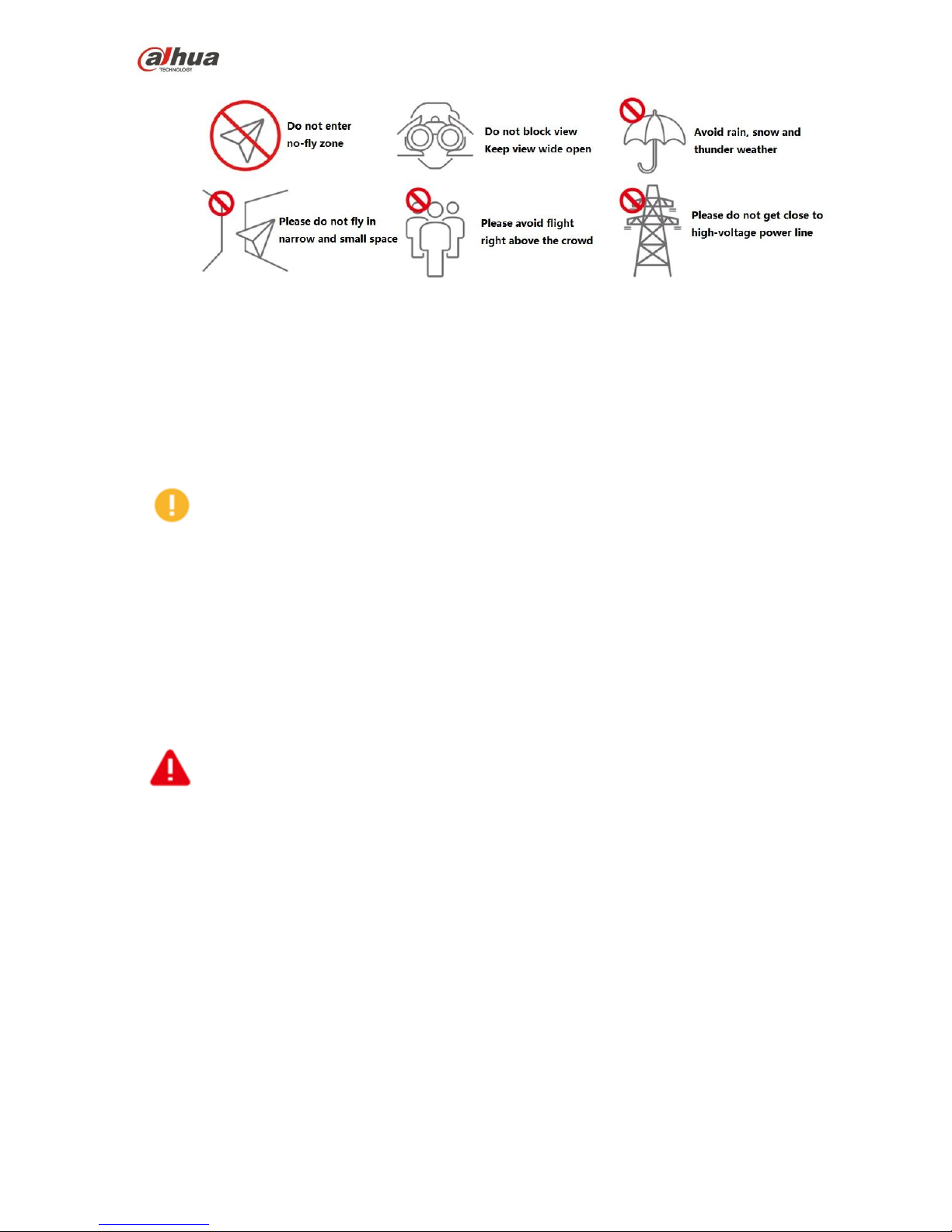
Please make flight in the environment which meets the following conditions:
Page 9
8
Keep away from no-fly zone, please do not enter no-fly zone.
Keep view wide open, make sure the device is flying within view range, please do not block visual field
Please do not fly the aircraft in rain, snow and thunder weather.
Please do not fly in narrow and small space.
Try not to fly right above the crowd, prevent personal injury.
Please do not get close to high-voltage power line.
Power Requirements
Caution
Please strictly conform to your local electrical safety codes.
Make sure the power supply is correct before operating the device.
The power source shall conform to the requirement of the Safety Extra Low Voltage (SELV) standard,
and supply power with rated voltage according to the Limited Power Source requirement of IEC60950-1.
Please note that the power supply requirement is subject to the device label.
Prevent the power cable from being trampled or pressed, especially the plug, power socket and the
junction extruded from the device.
Battery Attentions
Warning
It has to use the exclusive power adapter to charge the device provided by Dahua Technology, otherwise
it may cause damage to the battery or other unpredictable consequences.
It has to charge the device at a temperature which is between 0 and 50℃.
It has to distinguish positive and negative when charging the device, which is to prevent short circuit.
Please do not place the device close to fire source or inflammables.
Please do not charge and discharge the device in a situation where it is not guarded by people.
Please do no use undesignated battery to the device.
Please do not dismantle and destroy the battery without permission, water is not allowed to enter the
device, damages caused by human is not covered by warranty.
Please do not throw the battery into fire or make it exposed to the environment with high temperature.
Please do not dismantle or modify the battery, or make the battery transformed.
Avoid contact short circuit between positive and negative (Please do not place the battery together with
the objects such as necklace and hairpin etc. when carrying or storing the battery).
Please replace new battery in time when it is damaged.
Please charge the battery or discharge it to 30%~40% of remaining battery if it won't be used for a long
Page 10
9
time, and place it in a dry and cool environment.
If the battery leaks and the liquid enters eyes accidentally, please do not rub your eyes, you should wash
your eyes with clean water and see a doctor immediately.
Caution
It is normal the battery heats up after it is running for a period of time, because the discharge power is
quite big.
It is normal the battery heats up when it is being charged.
The cycle times of power battery is 300 in normal application situation.
Application Environment Requirements
Please do not aim the device at strong light (such as lighting, sunlight and so on).
Please transport, use and store the device in the allowed humidity and temperature range.
Please do not let any liquid flow into the device.
Please do not block the device ventilation.
Please do not press, vibrate or soak the device.
Please pack the device with default package or material with equivalent quality.
Operation and Maintenance Requirements
Warning
Please do not dismantle the device unprofessionally.
Please do not touch sensor CCD or CMOS directly, you can use hair drier to remove dust or dirt on the
lens surface.
Please use soft dry cloth or use clean soft cloth and dip a little mild detergent to clean the device.
Please do not touch or wipe the lens surface directly.
Please modify the user default password in time after login, which is to avoid being embezzled.
Please use the accessories provided by manufacturer and it shall be installed and repaired by
professional staff.
Please avoid laser beam radiation to the surface when using laser beam device.
Please do not provide two or more power supply modes to the device at the same time, otherwise it may
cause damage to the device.
Max 3 aircrafts are allowed to fly in the same area at the same time.
Disclaimer
This manual is for reference only. Please refer to the actual product for more details.
Minor differences might be found in user interface, and there might be deviation between the actual
value of some data and the value provided in the manual due to the reasons such as the real
environment is not stable. Please refer to the final explanation of the company if there is any doubt or
dispute.
All the designs and software are subject to change without prior written notice. The manual will be
regularly updated according to the product upgrade without prior announcement.
Please contact the supplier or customer service if there is any problem occurred when using the device.
Other trademarks and registered trademarks mentioned in the document are the properties of their
respective owners.
Page 11

10
1 Product Introduction
1.1 Overview
This series product is a quadcopters unmanned aerial vehicle (UAV). It is designed for the public security,
transportation; fire fighting, border defence, agricultural and forest area and energy source field. It
provides aerial video surveillance total solotions.
This series product includes aircraft, airborne equipment, remote control, and ground control station
(GCS).
Aircraft: It consists of the navigation system, flight control system and power system.
Airborne equipment: It consists of the PTZ control system, servo drive camera.
Remote control: It consists of the remote control system, touch screen.
GCS: It consists of the PC, image transmission system and ground control station software.
1.2 Features
Integrated Design
The aircraft adopts integrated design, neat appearance. Just need to dismantle and install the
propeller.
The remote control integrates the remote control and touch screen together. It is easy to operate and
has clear indicator.
Folded packages
The aircraft arm can be folded repeatedly.
The antennas can be folded repeatedly and dismantled, suitable to carry, transport and storage.
Quick Dismantle
The propeller adopts quick dismantle design structure, easy to open or fold the aircraft arm, antenna.
The PTZ camera adopts quick dismantle design structure, the installation screws are secured on the
shock absorb plate in case the screw become loss.
HD Video
The shock absorber board and shock absorber ball work together to guarantee PTZ camera stability.
30X optical camera is optional, professional HD video effect.
IR thermal camera is optional, suitable for special environments such as fire scene, or in the night
environment. It guarantees clear and HD video.
The remote control has snapshot button and record button. Easy to operate and instantly start
snapshot and record function.
Accurately Positioning
Empennage has built-in GSP system. Its positioning is accurate and in time.
Wireless Transmission
Aircraft has 4 antennas. Connect to the remote control, image transmission device to send and
receive the radio wave signal.
The remote control has 3 antennas. Connect to the aircraft, GCS to send and receive the radio wave
Page 12

11
signal.
The ground station connects to the large-size image transmission antenna. It is to receive image
data from the camera.
Low Battery Level Protection
When the low battery level triggers the aircraft to return to home, it can trigger low battery level
protection such as alarm, return to home and landing.
Flight Log
The ground station automatically records the flight record logs.
Intelligent Battery
Display remaining battery level. Battery has built-in power indicator light.
The balanced recharge function. Automatically balance the battery cells and voltage to protect
battery.
Over recharge protection. Battery automatically stops recharging when the voltage is full.
Sleep protection function. Battery automatically goes to sleep status when there is no operation
within 5 minutes.
Temperature protection function when recharge. The battery recharge temperature ranges from 0℃
to 50℃. Once the temperature is too high, battery automatically stops recharge otherwise it may
result in battery damage.
Communication function. The remote control and the GCS can get current remaining battery, voltage
information.
Flight Control
The aircraft adopts quadcopters system. It can switch among several flight modes and is easy to
control the flight direction.
Maximum taking off weight 10500g.
Electronic Fence
Support electronic fence (e-fence) function in case the aircraft is out of the specified flight zone.
Support customized e-fence settings.
Page 13
12
2 Structures
This series product includes aircraft, airborne equipment, remote control, and ground control station
(GCS).
This chapter introduces the structures of these four components. The detailed operations will be
introduced in chapter 3.
Note
All figures listed below and all dimensions listed here for reference only. The figure and the dimensions
may be slightly different from the user data due to measure position, measure accuracy, and position
indicator. Please refer to the actual product for detailed information.
2.1 Aircraft
Please refer to chapter 3 to install the propeller and unfold the whole device.
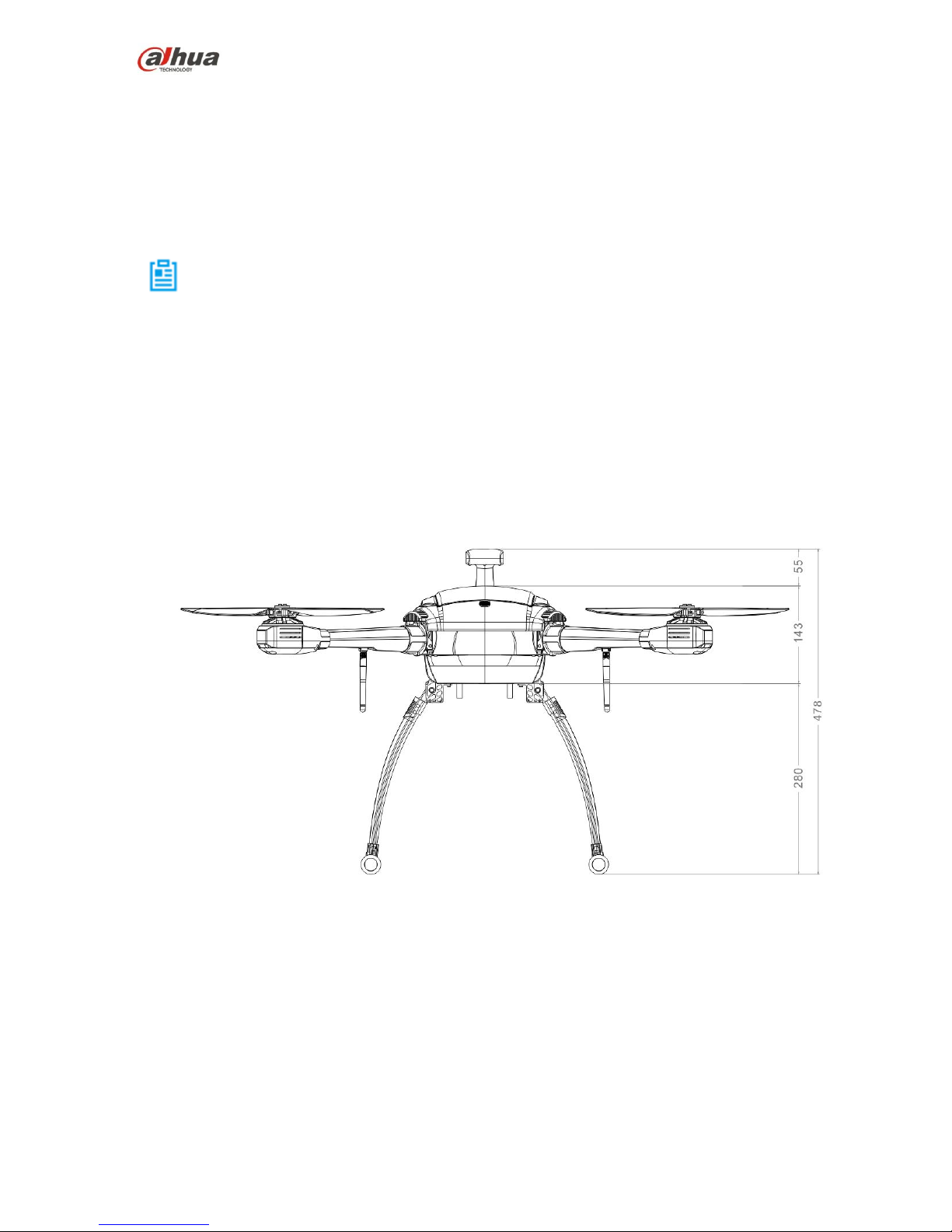
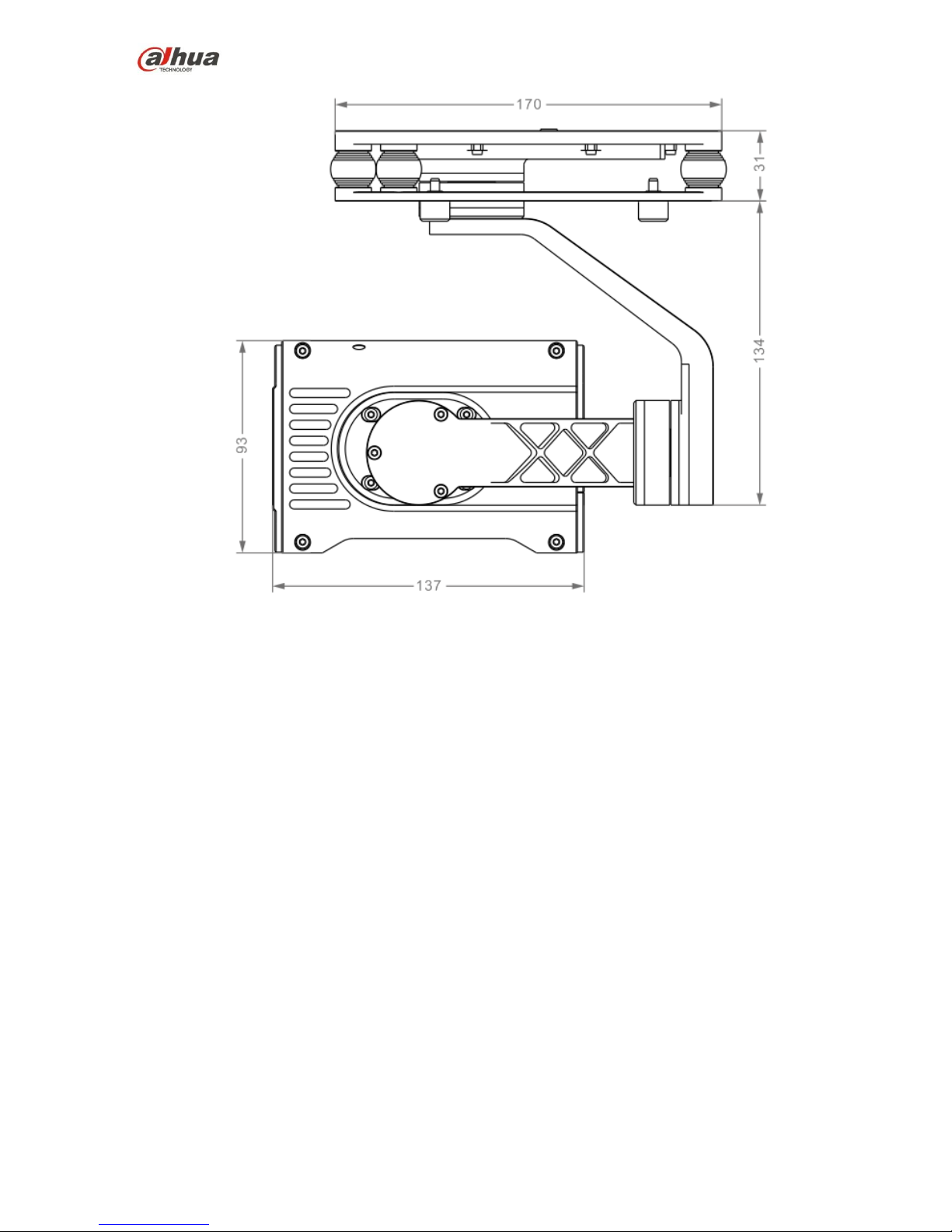
2.1.1 Product Dimensions
The aircraft is shown as in Figure 2-1 (front view) and Figure 2-2 (top view).
Figure 2-1
Page 14
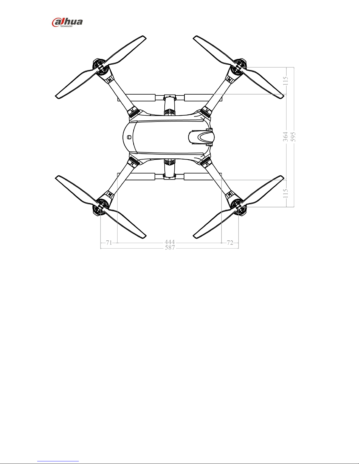
13
Figure 2-2
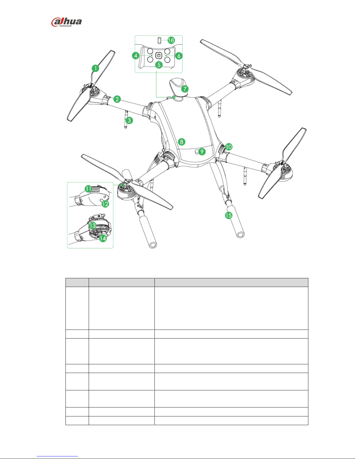
2.1.2 Structural Component
The aircraft components are shown as below. See Figure 2-3.
Page 15
14
Figure 2-3
Please refer to the following table for detailed information.
No.
Name
Function
1
Propeller
High-speed revolution to turn the motor power to push the
aircraft.
There are two pairs of propellers and they have different
structurers. Please adjust the installation positions
according to the actual situation.
2
Arm
Fold or unfold.
3
Antenna
Fold or unfold.
2 antennas are to receive the remote control signal.
1 antenna is for wireless image transmission.
4
Reserved
Reserved
5
Power switch (with
indicator)
Built-in indicator light. The light is green after connecting
power to the aircraft.
6
Pair button
When the remote control, GCS and the aircraft loses
remote connection, click it to pair again.
7
Empennage
Built-in GPS, compass.
8
Battery cover
Open to install or dismantle the battery.
Page 16

15
No.
Name
Function
9
Cover buckle
Move the buckle to open the battery box cover.
10
Fold arm button
To fold the arm.
11
Heat emission hole
For ventilation purpose when the motor is working.
12
LED
Red/green lights.
The adjacent two groups of the indicator lights are
always red, corresponding to the head of the aircraft.
The adjacent two groups of the indicator lights are
always green, corresponding to the tail of the aircraft.
13
Motor
To keep the propeller rotate.
14
Speed control unit
Sine drive, sound ascended or descends speed
performance.
15
Landing gear
Use remote control to open/close landing gear.
16
Aircraft status indicator
There are two modes: flashing or is always on. It displays
five colors: red, yellow, blue, green, purple. It is to indicate
system status, flight mode, upgrade status and etc.
Note
Refer to the appendix 2 for indicator light information and
definition.
2.2 Airborne Equipment
The aircraft has various airborne equipments such as visible light PTZ camera, IR PTZ camera and
speaker.
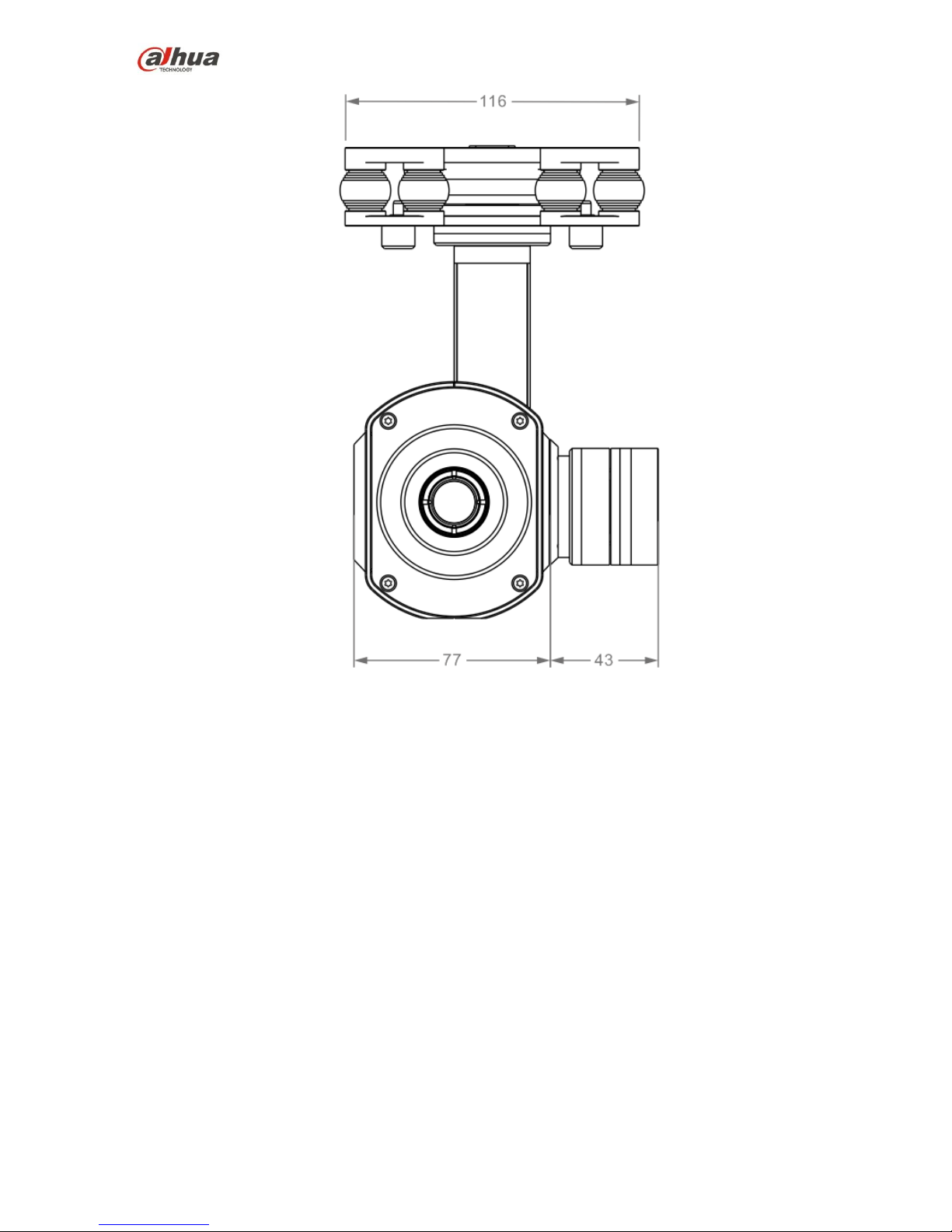
2.2.1 Visible Light PTZ Camera
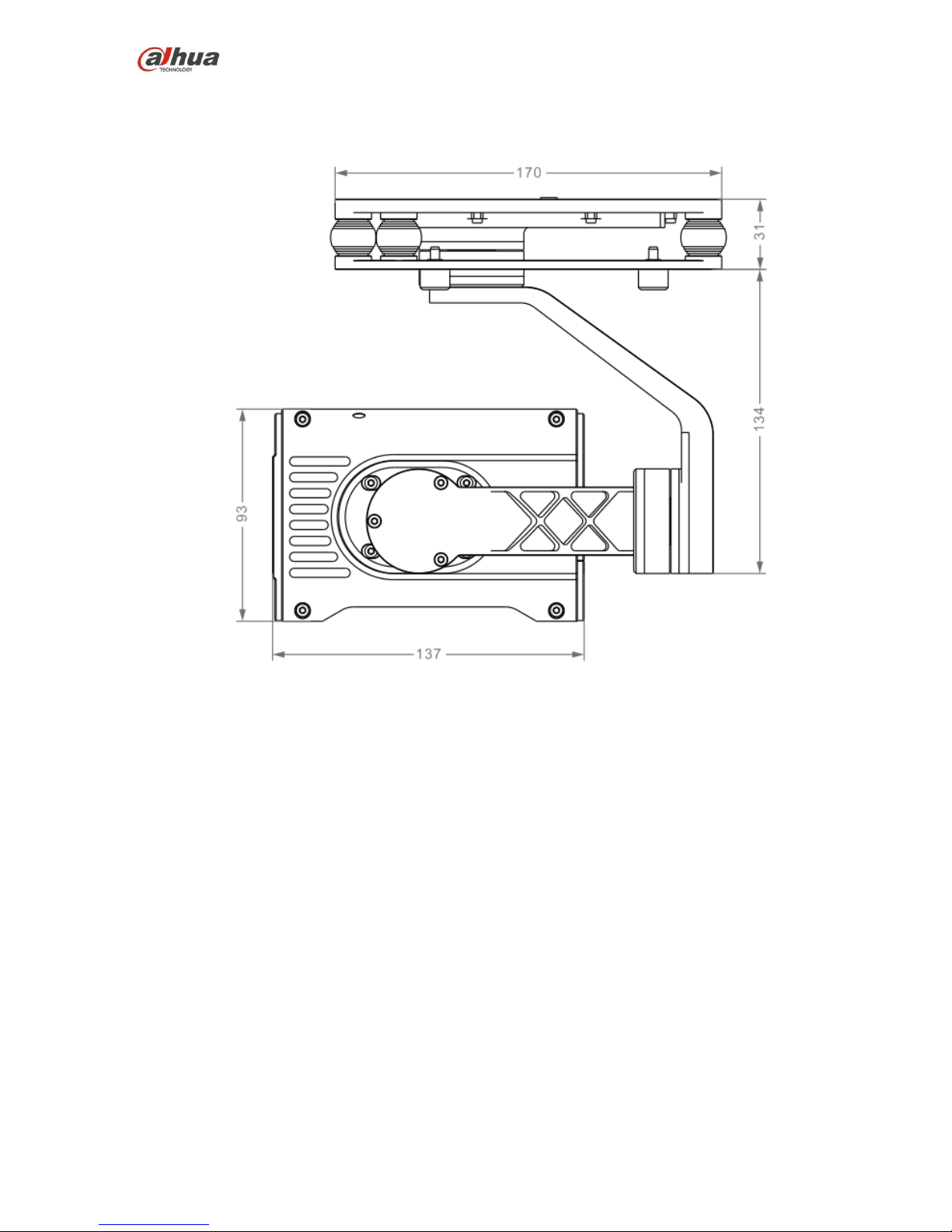
2.2.1.1 Dimensions
The visible light PTZ camera front view is shown as below. See Figure 2-4.
Page 17
16
Figure 2-4
The visual light PTZ camera side view is shown as below. See Figure 2-5.
Page 18

17
Figure 2-5
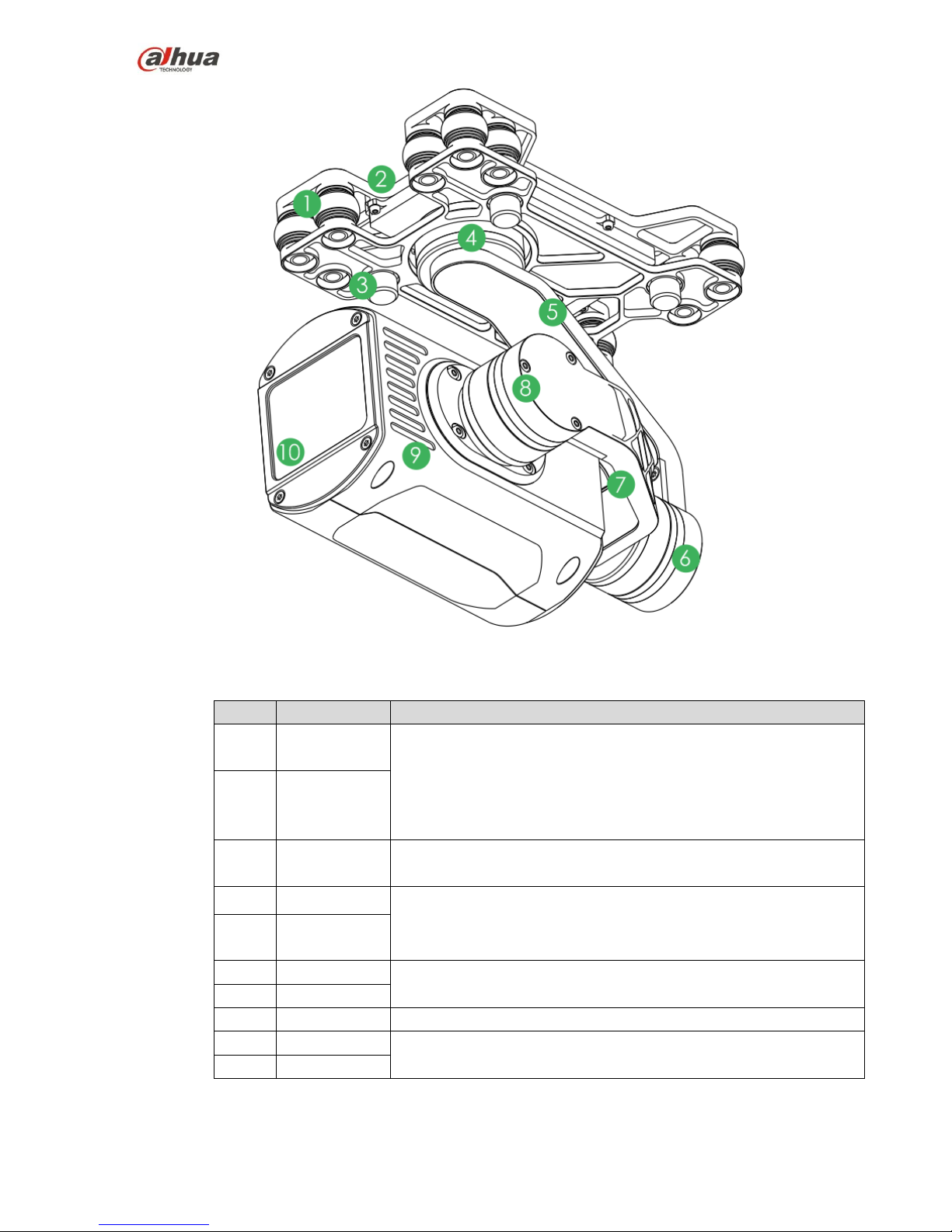
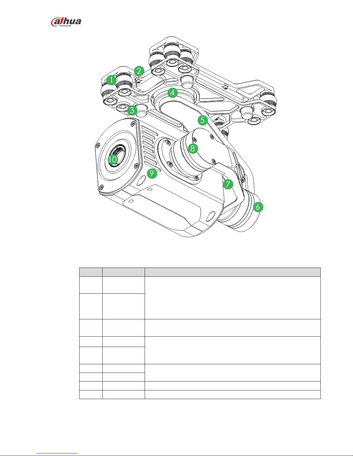
2.2.1.2 Structural Component
The visible light PTZ camera structure is shown as below. See Figure 2-6.
Page 19
18
Figure 2-6
Please refer to the following table for detailed information.
No.
Name
Function
1
Shock
absorber ball
It is to reduce the PTZ camera vibration during the flight to get clear
video.
2
Shock
absorber
board
3
Installation
screw
Secure the PTZ camera on the aircraft.
4
Course motor
Control the camera horizontal direction.
5
Course
rotation arm
6
Motor
Control the camera horizontal pitch degrees.
7
Rotation arm
8
Pitch motor
Control the camera tilt pitch degrees.
9
Camera
Shoot video.
10
Lens
Page 20
19
2.2.2 IR PTZ Camera
2.2.2.1 Dimensions
The IR PTZ camera front view is shown as below. See Figure 2-7.
Figure 2-7
The IR PTZ camera side view is shown as below. See Figure 2-8.
Page 21
20
Figure 2-8
2.2.2.2 Structural Component
The structural component is shown as below. See Figure 2-9.
Page 22
21
Figure 2-9
Please refer to the following table for detailed information.
No.
Name
Function
1
Shock
absorber ball
It is to reduce the PTZ camera vibration during the flight to get clear
video.
2
Shock
absorber
board
3
Installation
screw
Secure the PTZ camera on the aircraft.
4
Course motor
Control the camera horizontal direction.
5
Course
rotation arm
6
Motor
Control the camera horizontal pitch degrees.
7
Rotation arm
8
Pitch motor
Control the camera tilt pitch degrees.
9
Camera
Shoot video.
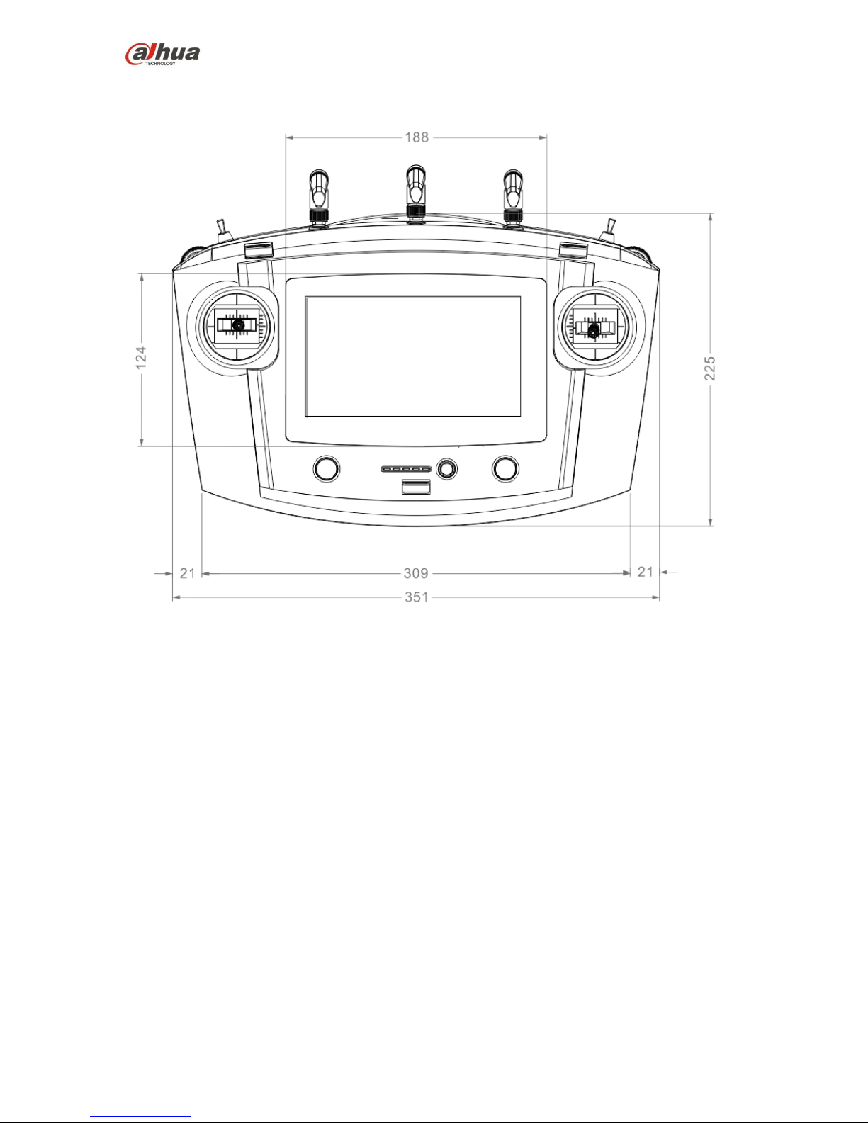
2.3 Remote Control
Page 23
22
2.3.1 Dimensions
The remote control front view l is shown as below. See Figure 2-10.
Figure 2-10
The remote control side view is shown as in Figure 2-11.
Page 24

23
Figure 2-11
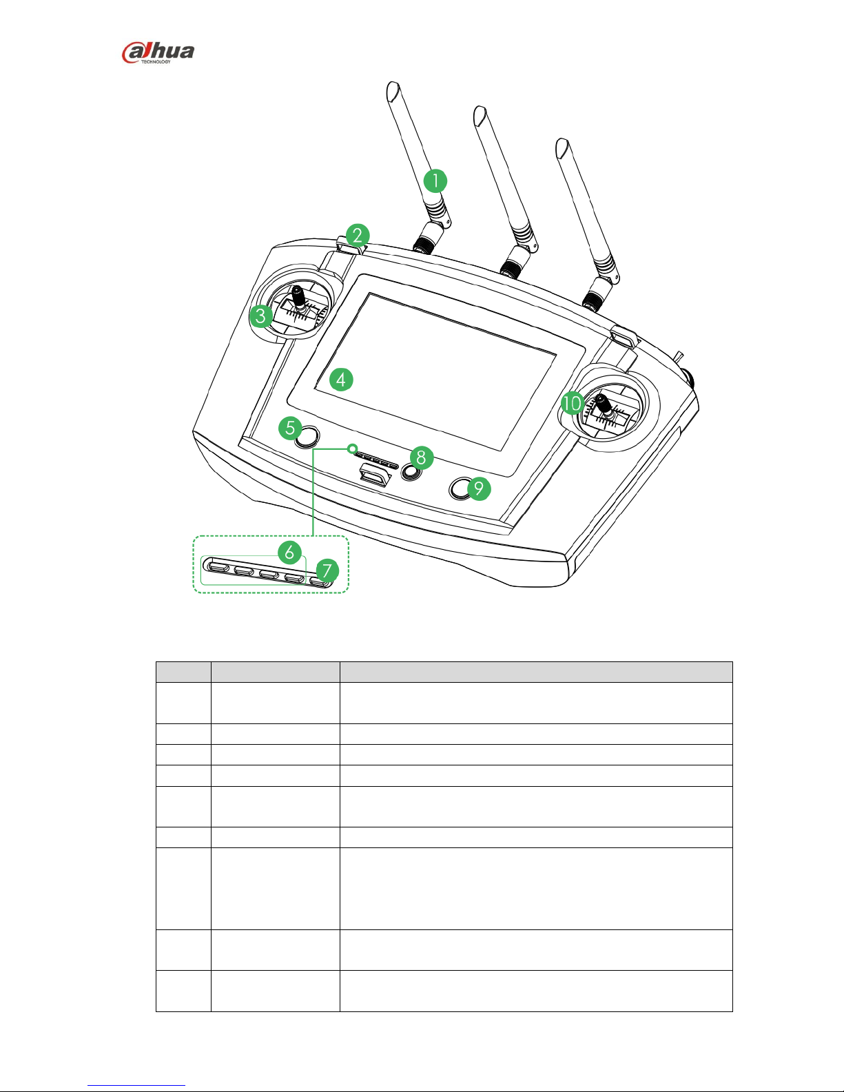
2.3.2 Structural Component
2.3.2.1 Front Panel
The front panel is shown as in Figure 2-12.
Page 25
24
Figure 2-12
Please refer to the following table for detailed information.
No.
Name
Function
1
Antenna
Establish the remote control relationship with the aircraft and
receive the video.
2
Hanger
Fix the hanger rope.
3
Left control stick
Control the aircraft flight status.
4
Touch screen
Set parameters and preview the video.
5
Landing gear
button
Open or close the landing gear.
6
Battery indicator
Each bar presents the 25% battery power.
7
Charging indicator
The indicator light is on when connect the power to the
recharge port.
Red light is on: recharging.
Green light is on: recharge is finish.
8
One-click return
home
Control aircraft to automatically return to home.
9
One-click take
off/landing button
Control aircraft to take off or landing. The take off height is 2
meters.
Page 26
25
No.
Name
Function
10
Right control stick
Control the aircraft flight status.
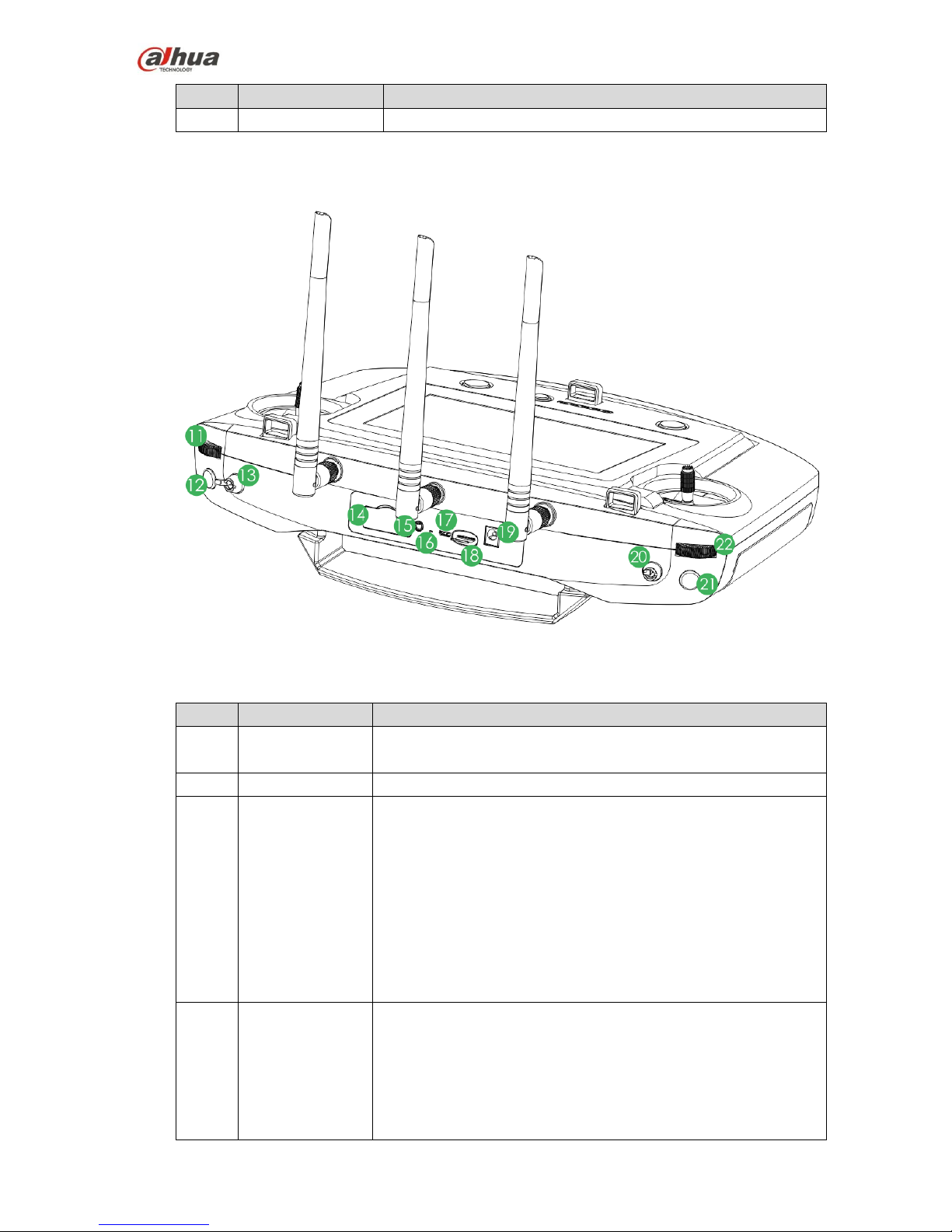
2.3.2.2 Side Panel
The side panel components are shown as in Figure 2-13.
Figure 2-13
Please refer to the following sheet for front panel button information.
No.
Name
Function
11
PTZ course
pulley
Control the camera horizontal shoot angle.
12
Snapshot
Shortly push the button to snapshot an image.
13
Flight mode lever
3-level lever to select flight mode.
Upper level: intelligent flight mode. The aircraft flight
according to the specified course.
Middle level: flight at the specified height. When the throttle
lever is at the default mode, the aircraft flight at the same
height.
Lower level: Hover at the specified position. When all levers
are at the default mode, the aircraft hovers at the same
position.
14
4G SIM slot
Insert SIM card: Open the silica gel, the SIM card with the
chip is facing down. Insert the card to the slot horizontally
and then close the silica gel.
Remove SIM card: open the silica gel, press the left button
for the short time, system automatically pops up SIM card a
little bit, and then remove the SIM card. Close the silica gel,.
Page 27
26
No.
Name
Function
15
Audio output port
Connect to earphone, sound box and etc. It is to play audio.
16
Remote control
reset
Reserved.
17
Micro USB port
Insert data cable to connect to PC. It is to transmit the data to the
PC.
18
SD slot
Insert SD card: The SD card with the chip is facing down.
Insert the card to the slot horizontally.
Remove SD card: Press SD card, system automatically
pops up SD card a little bit, and then remove.
19
Power interface
Input DC 12V power.
20
PTZ mode lever
2-level lever. It is to select PTZ mode.
Upper lever: Lock the course direction. No matter what the
aircraft flight angles are, the PTZ camera is facing the same
degree to shoot.
Lower level: Follow the flight mode. The PTZ camera angle
is changing according to the aircraft flight directions.
21
Record button
Press the button for a short time to record. Press it for a short
time again to stop the record.
22
PTZ pitch pulley
Control the camera lens pitch angles.
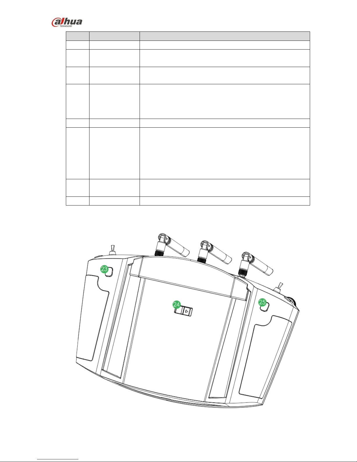
2.3.2.3 Rear Panel
The rear panel is shown as in Figure 2-14.
Figure 2-14
Page 28
27
Please refer to the following table for detailed information.
No.
Name
Function
23
Zoom in button
Press it for a short time, it is to zoom in the camera.
Press it for a long time, it is to zoom in until the camera
reaches the max rates.
24
Power switch
Open or close the remote control.
25
Zoon out button
Press it for a short time, it is to zoom out the camera.
Press it for a long time, it is to zoom out until the camera
reaches the min rates.
2.3.3 Buttons
Note
Refer to chapter 4 for the joystick and flight mode lever button information.
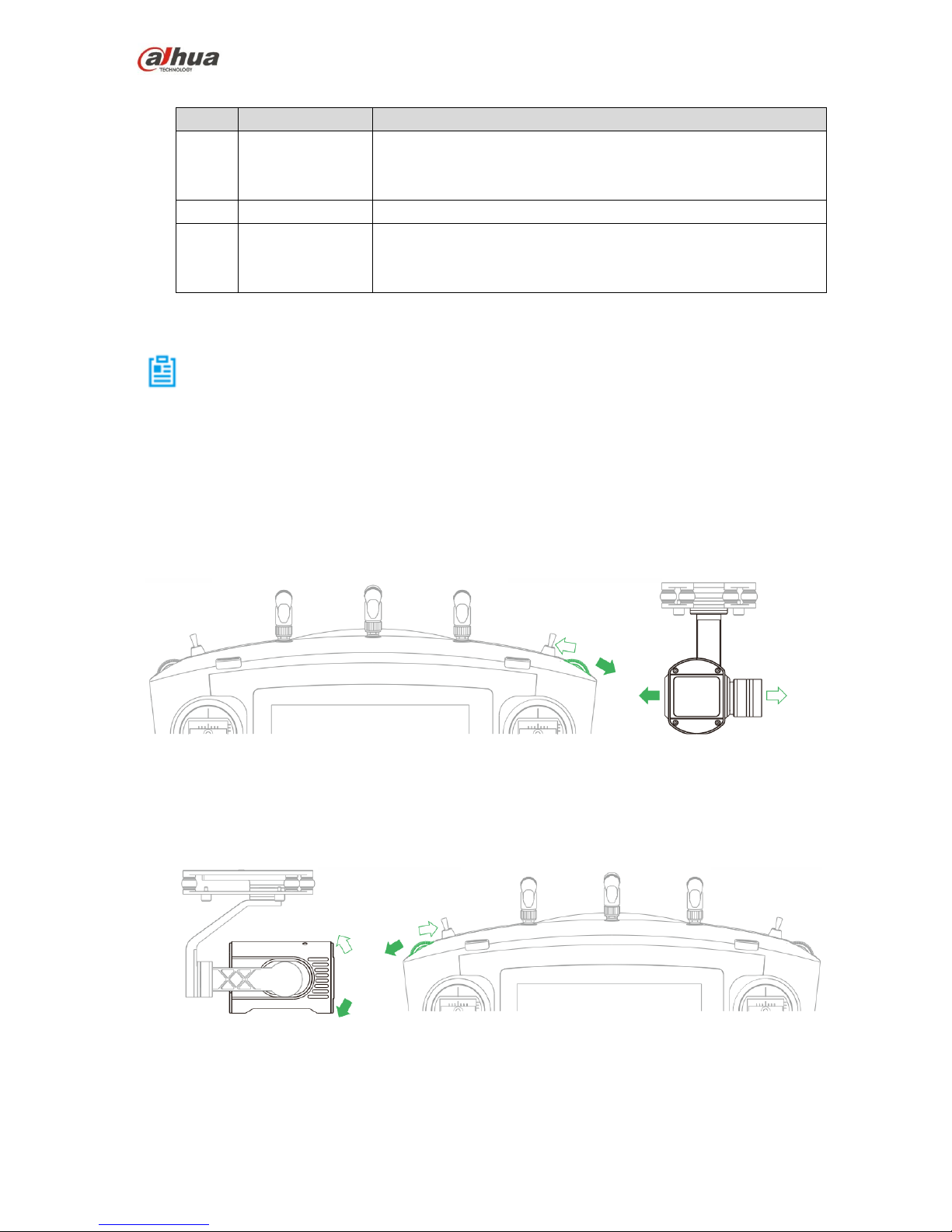
2.3.3.1 Pulley wheel
PTZ flight pulley wheel. It is to control the camera horizontal shoot angle. See Figure 2-15.
Pulley wheel to the left: PTZ to the right.
Pulley wheel to the right:PTZ to the left.
Figure 2-15
PTZ pitch pulley wheel. It is to control the camera pitch angle. See Figure 2-16.
Pulley wheel to the left: Camera lens to the down side.
Pulley wheel to the right: Camera lens to the up side.
Figure 2-16
2.3.3.2 PTZ Mode Lever
Use PTZ mode lever to control the PTZ camera shoot angle. See Figure 2-17.
Page 29
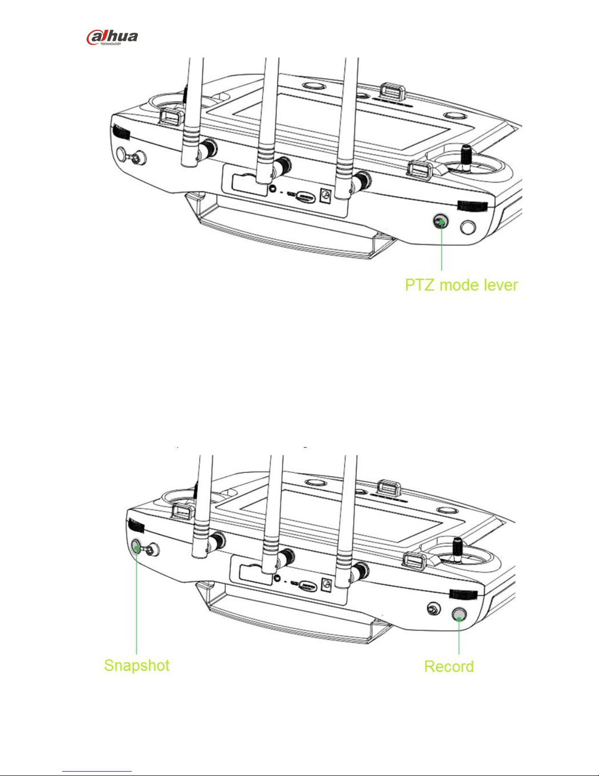
28
Figure 2-17
2-level lever:
Upper lever: Lock the course direction. No matter what the aircraft flight angles are, the PTZ camera
is facing the same degree to shoot.
Lower level: Follow the flight mode. The PTZ camera angle is changing according to the aircraft flight
directions.
2.3.3.3 Shoot
The record and snapshot button is shown as in Figure 2-18.
Figure 2-18
Page 30
29
Snapshot: Press snapshot button for a short time to sanpshot an image.
Record: Press record button for a short time to begin recording video. Press it for a short time again to
stop the record.
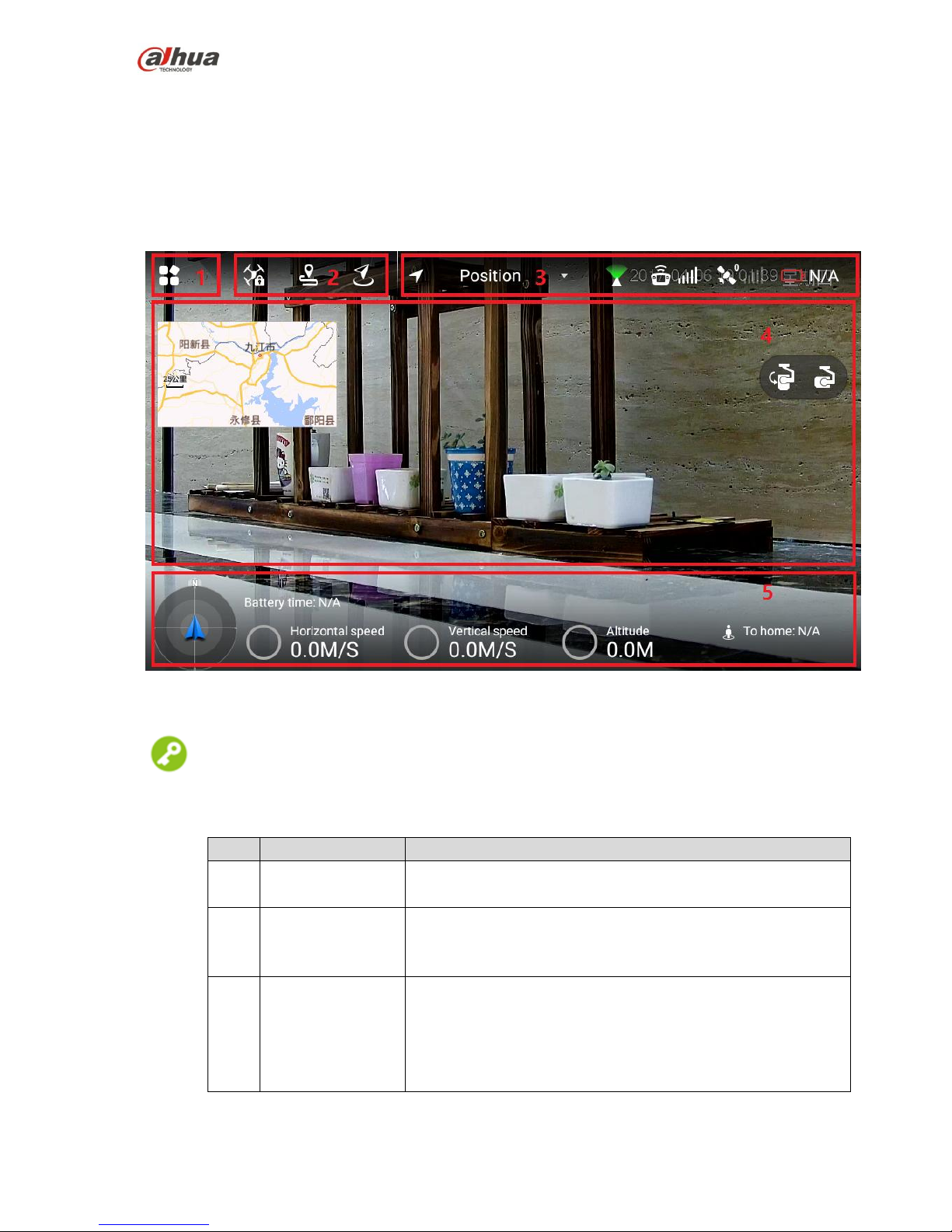
2.3.4 Operation Interface
After enable the remote control power, system enters the main interface.
The main interface includes the following function panes. See Figure 2-19
Figure 2-19
Tips
Pinch up any position on the preview interface to hide the setting menu, function bar and status bar. Pinch
down any position on the preview interface to view them again.
SN
Name
Function
1
Menu
Click to go to the setting menu.
Please refer to chapter 2.3.4.4 Settings for detailed information.
2
General functions
Set HOME position and lock mode.
Please refer to chapter 2.3.4.3 General function buttons for
detailed information.
3
Status bar1
Display flight mode, PTZ mode, remote control signal intensity,
GPS satellite amount, signal intensity , remote control
remaining power.
Please refer to chapter 2.3.4.1.1 Status display bar 1 for
detailed information.
Page 31

30
SN
Name
Function
4
Preview window
Quickly switch video preview and map preview to display
prompt information.
Please refer to chapter 2.3.4.2 Preview for detailed information.
5
Status bar 2
Display remaining flight time, aircraft speed, height, distance
from the HOME.
Please refer to chapter 2.3.4.1.2 Status display bar 2 for
detailed information.
2.3.4.1 System Status
2.3.4.1.1 Status display bar 1
The status display bar 1 is shown as below. See Figure 2-20.
Figure 2-20
Please refer to the following table for detailed information.
Icon
Name
Function
Flight
mode
Display current aircraft flight mode.
PTZ mode
This icon has two statuses:
: When the PTZ lever is at the upper
level, the PTZ camera has locked the course
direction. No matter how aircraft angle changes,
the PTZ camera is still facing the same direction
to shoot.
: When the PTZ lever is at the lower
level, the PTZ camera direction is following the
flight mode. The shoot angle is changing
according to the aircraft course angle.
Remote
control
intensity
There are max 5 bars. The more the highlighted bar
amount is, the stronger the remote control effect is .
GPS
satellite
and the
signal
intensity
The number on the left side is the GPS satellite
amount.
The GPS signal intensity is shown on the right.
There are max 5 bars. The more the highlighted
bar amount is, the stronger the remote control
effect is .
Page 32

31
Icon
Name
Function
Reaming
power
When the remaining power is low, please complete
the flight as soon as possible and replace the aircraft
battery.
2.3.4.1.2 Status display bar 2
The status display bar 2 is shown as below. See Figure 2-21.
Figure 2-21
Please refer to the following table for detailed information.
Icon
Name
Function
Aircraft direction
It is to indicate the aircraft direction on the
geographic position.
Battery time
(remaining flight
time)
When the flight time is running out, please
complete the flight as soon as possible and
recharge the aircraft.
Note
The flight time displayed here for reference
only. The actual flgiht time may affect by the
enviroment and etc. It may be different from
the actual flight time.
Horizontal speed
The aircraft forward and backward speed
on the horizontal direction.
Vertical speed
aircraft vertical ascend and descend speed
Altitude
The aircraft relative altitude from the taking
off position.
Distance from the
HOME
The aircraft distance from the HOME.
The value displayed here is the project
distance on the horizontal space.
2.3.4.2 Preview
Click the window on the top left corner; it is to switch between video preview mode and map preview
mode.
Page 33

32
: Prompt information is displayed on the right side of the icon. Click the icon to view message list.
2.3.4.2.1 Video preview mode
The default preview mode is shown as in Figure 2-22.
Figure 2-22
In this mode, the map is displayed in the small window at the top left corner of the preview interface.
In this mode, the large window is to display the camera video outputting to the remote control.
2.3.4.2.2 Map Preview Mode
The map preview mode is shown as below. See Figure 2-23.
Page 34

33
Figure 2-23
In this mode, the video camera outputting to the remote control is displayed at the small window on
the top left corner of the preview interface.
In this mode, the large window displays the aircraft position on the map.
The function buttons on the map preview interface is listed below:
: Lock map direction button. Current top direction is always the north. When the remote control has
changed, the map rotates accordingly, while the east/south/west/north always maintains the previous
direction.
: Map display mode switch button. Switch to use map or the 2D image to display the map.
: Using Aircraft as the center. Quickly switch to the aircraft current position and use its position as
the center.
2.3.4.3 General function buttons
Lock Mode
Click it to select the aircraft lock mode on the pop-up dialogue box. See Figure 2-24.
Figure 2-24
2.3.4.4 Settings
Page 35

34
Click to go to setting interface.
The 1st
menu
The 2nd menu
The 3rd
menu
Function
Remote
control
Control stick
mode
-
There are two modes.
Please refer to chapter 4.2.4 Manual Flight
control for detailed information.
Remote control
calibration
-
Calibrate the remote control
Please refer to chapter 3.9.2 Remote
control calibration for detailed information.
Remote control
pair
-
Pair remote control, ground station, aircraft.
Please refer to chapter 9 Appendix for
detailed information.
Flight
Enable e-fence
-
Enable or disable e-fence
Please refer to chapter 4.4.3.2 Enable
e-fence for detailed information.
E-fence
-
Set e-fence parameters and trigger actions
Please refer to chapter 4.4.3.1 E-fence
area settings for detailed information.
Preview
Preview image
size
-
Set preview image size
Please refer to chapter 4.4.4.1 Image
transmission size for detailed information.
Camera
Photo
-
Set snapshot image size
Please refer to chapter 4.4.4.2 Photo
settings for detailed information.
Video
-
Set video record size
Please refer to chapter 4.4.4.3 Video
settings for detailed information.
Advanced
Image
Set brightness, contrast, saturation,
sharpness, gamma.
Please refer to chapter 4.4.4.4 Image
settings for detailed information.
General
Aircraft firmware
upgrade
-
Check firmware status and upgrade
Please refer to chapter 4.4.4.1 Aircraft
firmware upgrade for detailed information.
APP upgrade
-
Check APP status and upgrade
Please refer to chapter 6.2.1 APP upgrade
for detailed information.
Other
Geomagneti
sm
calibration
Calibrate geomagnetism
Please refer to chapter 3.9.5 Geomagnetic
abnormality for detailed information.
Acceleromet
er calibration
Calibrate accelerometer
Please refer to chapter 3.9.3 Accelerometer
calibration for detailed information.
Offline map
Add or delete offline map.
Please refer to chapter 6.2.2 Remote
Page 36

35
The 1st
menu
The 2nd menu
The 3rd
menu
Function
control offline map download and upgrade
for detailed information.
Brightness
Adjust laptop brightness.
Please refer to chapter 4.4.4.5 Brightness
adjustment for detailed information.
Currently
connected to
SSID
-
Display currently connected aircraft.
On settings interface, click to go back to the previous menu and click to exit settings.
2.4 Ground Control Station (GCS)
2.4.1 Product Dimensions
The ground station front view is shown as below. See Figure 2-25.
Figure 2-25
The ground station side view is shown as below. See Figure 2-26.
Page 37

36
Figure 2-26
2.4.2 Structural Component
The ground structural component is shown as below. See Figure 2-27.
Figure 2-27
Please refer to the following table for detailed information.
SN
Name
Function
1
Image
transmission
antenna
It is to receive the image transmission signal from the aircraft.
2
Tripod
Fix the image transmission antenna
3
Height adjustment
buckle
Adjust tripod height
Page 38

37
SN
Name
Function
4
Antenna feeder
Connect the image transmission antenna with the ground
control station.
5
Image
transmission
antenna port
Connect to image transmission antenna feeder.
6
Screen buckle
Press to open the ground control station
7
Relay antenna
For the data transmission between the ground control station
and the remote control.
8
Touch screen
For operations on the ground station.
9
Touchpad
10
Touch pen
11
System boot up
button
Boot up ground station OS.
When device is off, push to the right to boot up.
When device is on, push to the right and maintain for at
least 3 seconds to shut down forcedly.
12
Image
transmission
button
Enable/disable ground control station image transmission
system.
When device is off, press once for a short time, the built-in
red indicator light is on, the image transmission system is
on.
When device on, press once for a short time, the built-in
red indictor light is off, the image transmission system is
off.
13
Power port
Ground station recharge port
2.4.3 Operation GUI
Click to open the Ground Control Station (GCS), enter the main interface.
GCS has the following function modules. See Figure 2-28.
Page 39

38
Figure 2-28
Please refer to the following table for detailed information.
SN
Name
Function
1
Setting menu
Set aircraft parameters and set preview interface.
Please refer to chapter 2.4.3.1 Settings for detailed information.
2
Status display bar
1
It is to display preview alarm information, GPS status, battery
status, flight mode.
Please refer to chapter 2.4.3.2.1 Status display bar 1 for
detailed information.
3
Preview window
Quickly switch video preview and map preview.
Please refer to chapter 2.4.3.1.2 Preview for detailed
information.
4
Status display bar
2
It is to display aircraft flight gesture, flight parameters, flight
directions and etc.
Please refer to chapter 2.4.3.2.2 Status display bar 2 for
detailed information.
2.4.3.1 Settings
2.4.3.1.1 Aircraft settings
Click to go to the aircraft setting interface.
The 1st Menu
The 2nd Menu
Note
Preview
Remote control
Set the mapping between the control stick and
the channel.
Flight mode
View aircraft flight mode.
Battery
View aircraft battery status
Page 40

39
The 1st Menu
The 2nd Menu
Note
Security
View aircraft security parameters
Offline map
Add new task
Add a new offline map.
Please refer to chapter 6.3.3.1 Download
offline map for detailed information.
Default Tile Set
System default offline map .
When the network connection is OK, system
automatically downloads current position map.
Pair
frequency
-
Pair aircraft, ground control station, remote
control.
Please refer to chapter 9 Appendix system
paring for detailed information.
Note
All corresponding components have
completed the pair process. Usually user do
not need to pair again.
Diagnosis
-
Diagnosis and repair the ground control station
Please refer to chapter 3.9.1 Aircraft diagnosis
for detailed information.
Options
-
Set offline map buffer
Please refer to chapter 6.3.3.3 Set offline map
disk buffer for detailed information.
2.4.3.1.2 Preview
Click to enter preview interface.
Click the map preview window at the bottom left of the preview interface, it is to switch between the video
preview and map preview mode.
Video Preview Mode
The system default preview mode is the video preview. See Figure 2-29.
Page 41

40
Figure 2-29
In this mode, the map is displayed in the small window at the bottom left of the preview interface.
In this mode, the large window displays video camera transmitting to the ground control station.
Note
Armed: Aircraft armed button. The aircraft cannot take off since it is locked.
Disarm: Aircraft disarmed button. The aircraft has unlocked and is ready to take off.
Map preview mode
The map preview mode is shown as in Figure 2-30.
Page 42

41
Figure 2-30
In this mode, there is a small window at the bottom left of the preview interface. It is to display the
video from the camera to the ground control station.
In this mode, the large window is to display the aircraft position on the map.
In map preview mode, the function buttons are listed below:
Flight track button. Quickly switch to the aircraft current map position and use the aircraft
current position as the center to follow up.
Map display mode switch button. Quickly switch the map. The map includes satellite map,
topography map, and street map. It can clear flight track too.
2.4.3.2 System status display
2.4.3.2.1 Status display bar 1
The status display bar 1 is shown as in Figure 2-31.
Figure 2-31
Please refer to the following table for detailed information.
Icon
Name
Function
Alarm
information
It is to view all alarm information on the main
interface.
Page 43

42
Icon
Name
Function
Note
When there is an alarm prompt, there is yellow
framed alarm information on the preview interface. It
lasts for 10 seconds and then disappear.
GPS satellite
amount and
dilution precision
It is to check all parameters conform to the aircraft
flight conditions or not.
The number at the top right corner is the GPS
satellite amount. When the GPS amount is
equal to or larger than the 6, the aircraft is
allowed to take off.
The number at the bottom right corner is the
GPS dilution precision. When the dilution
precision is equal to or smaller than 1.4, the
aircraft is allowed to take off.
Reaming battery
percentage
View aircraft remaining power. Please terminate the
flight as soon as possible and replace the aircraft
battery if the remaining battery percentage is too low.
(Hover)
Flight mode
Display current aircraft flight mode.
Please refer to chapter 4.1 Flight mode for detailed
information.
Note
The displayed flight mode on the ground control
station and remote control are the same.
2.4.3.2.2 Status display bar 2
The Status display bar 2 is shown as in Figure 2-32.
Page 44

43
Figure 2-32
Please refer to the following table for detailed information.
Icon
Name
Function
1
Aircraft flight
posture and
control parameters
settings
Display aircraft realtime flight posture. Display pitch
degree when the aircraft is rolling or pitch.
Rolling pitch, each bar presents 15 degrees.
Pitch: each small bar presents 5 degrees and each
big bar presents 10 degrees.
Page 45

44
Icon
Name
Function
Aircraft control parameters.
Click to set to display aircrasft real-time
control parameters.
Click OK to save the parameters.
2
Aircraft control
parameters
Display aircraft control parameters.
3
Flight direction
Display aircraft course moving angles.
The device uses N/S/W/E to present aircraft flight
direction.
The number in the middle of the tray is to display the
aircraft moving angles. Each small bar presents 10
degrees. Each large bar presents 30 degrees.
Page 46

45
3 Flight Preparation
Note
The following chapter is going to introduce complete flow in details before the aircraft unlocked and
takes off.
Please select operation according to the actual situation after the first flight is over if it is not the used
for the first time.
Caution
Please operate by strictly conforming to the steps described in this chapter; the operation sequence can't
be reversed.
Please refer to Figure 3-1 for the flow of flight preparation phase.
Flight
Preparation
Phase
Unpack
↓
Check remaining battery→Low battery, please
charge
↓ ↙
Prepare airborne device
↓
Prepare aircraft
↓
Prepare ground station
↓
Prepare remote control
↓
Enable aircraft power
↓
Check debugging→All debugging is
normal
↓ ↙
Install propellers
Figure 3-1
3.1 Unpack
Take out aircraft, battery, propellers, remote control and ground station from the packing box.
3.2 Check Remaining Battery
Check the remaining battery of aircraft battery, remote control and ground station, you can implement the
subsequent steps after confirming that the battery reaches the standard.
Please refer to chapter 3.3 charging when the battery is low, please implement the sebsequent steps after
charging.
3.2.1 Aircraft
Page 47

46
3.2.1.1 Aircraft Battery Check
Short press the battery indication button on the aircraft battery and check the number of indicator lights
which are on, which is shown in Figure 3-2.
Figure 3-2
At normal temperature, the remaining battery is required to be ≥2.
The aircraft is required to take off with full battery when normal temperature is lower than -10℃.
3.2.1.2 Aircraft Remaining Battery
There are three statuses for each indicator light of the aircraft battery, which are normally on, flash and
off.
The following table describes remaining battery percentage when the indicator light is in different status,
"●" means normally on, "◎" means flash and "○" means off, which is shown in Table 3-1.
SN
Indicator light status
Remaining battery percentage range
1
●●●●~●●●◎
100%~87.5%
2
●●●◎~●●●○
87.5%~75%
3
●●●○~●●◎○
75%~62.5%
4
●●◎○~●●○○
62.5%~50%
5
●●○○~●◎○○
50%~37.5%
6
●◎○○~●○○○
37.5%~25%
7
●○○○~◎○○○
25%~12.5%
8
◎○○○~○○○○
12.5%~0
Table 3-1
3.2.2 Remote Control
3.2.2.1 Remote Control Battery Check
Move the power switch to the arrow location, check the number of indicator lights which are on.
Figure 3-3
Page 48

47
Figure 3-4
At normal temperature, the remaining battery is required to be ≥2.
The remaining battery is required to be ≥3 when the temperature is lower than -10℃.
3.2.2.2 Remote Control Remaining Battery
There are two statuses for each indicator light of remote control, which are normally on and off.
The following table describes remaining battery percentage when the indicator light is in different status,
"●" means normally on and "○" means off, which is shown in Table 3-2.
SN
Indicator light status
Remaining battery percentage
1
●●●●~●●●○
100%~75%
2
●●●○~●●○○
75%~50%
3
●●○○~●○○○
50%~25%
4
●○○○~○○○○
25%~0
Table 3-2
3.2.3 Ground Station Battery Check
Move the system boot button to the right and the system starts up, which is shown in Figure 3-5.
Figure 3-5
You can check remaining battery percentage on the upper right corner of the operating system, which is
shown in Figure 3-6.
Figure 3-6
Page 49

48
The remaining battery is required to be ≥ 30% at normal temperature.
The remaining battery is required to be ≥ 40% when the temperature is lower than -10℃.
3.3 Charging
Note
It doesn't need to implement the following chapter if the remaining battery is enough.
3.3.1 Aircraft Battery Charging
The whole charging period (from 0 to 100) is about 2 hours.
Figure 3-7
Step 1
Open the battery cover, unfasten the battery fixing band and take out battery.
Step 2
Connect charging adapter cable to the 6S balance port and charging power port of the charger, and
connect the charger to AC power.
Step 3
Insert the battery into the battery port of the charging adapter cable.
Step 4
Rotate the black button and select CHR.
Step 5
Press the button. The value displayed by LED nixie tube bounces and flashes, and then turn the button to
adjust current which is recommended to be 15A. Press the button again to select after adjustment is over.
Step 6
Short press the battery indicator light button once, and then long press it for 3 seconds, turn on the
indicator light which displays battery.
Step 7
Long press the button to start charging and wait for the charger prompt. It means charging is completed
when the charger beeps 5 times and LED nixie tube displays DONE.
Figure 3-8
Step 8
First disconnect it from the power socket and then other cables after chargin is completed.
Page 50

49
3.3.2 Remote Control Charging
The entire charging period (battery from 0 to 100) needs approximately 3.5 hours.
Please charge the remote control when its power is off.
Step 1
Connect the remote control to power adapter by charging cable.
Figure 3-9
Step 2
Connect power adapter to AC power (AC 100V-240V).
Step 3
Check charging status: it means the remote control is charging when the indicator light is red and
normally on. It means charging is done when the indicator light becomes green and normally on, which is
shown in the following figure.
Figure 3-10
Step 4
First disconnect the remote control from the power socket and then all other cables after charging is
done.
3.3.3 Ground Station Charging
The entire charging period (battery from 0 to 100) needs approximately 3.5 hours.
Step 1
Connect ground station to power adapter with charging cable.
Figure 3-11
Page 51

50
Step 2
Connect power adapter to AC power (AC 100V-240V).
Step 3
Check charging status: it means the ground station is charging when the indicator light on the right of
ground station handle is orange and normally on. It means charging is done when the indicator light
becomes green and normally on.
Step 4
First disconnect the ground station from power socket and then all other cables after charging is done.
3.4 Prepare Airborne Equipment
Note
The following chapter is optional for operation.
Please implement demounting step first and then connection step when the PTZ camera needs to be
replaced.
It only needs to implement demounting step when the aircraft flies directly without PTZ camera.
3.4.1 Demount PTZ Camera
Step 1
Loosen four mounting screws, which is shown in the following figure.
Figure 3-12
Step 2
Pull out the data cable.
Page 52

51
Figure 3-13
3.4.2 Install PTZ Camera
Step 1
Insert the port of aircraft bottom data cable into the upper port on the vibration damper plate of the PTZ
camera.
Step 2
Align four mounting screws with the hole sites of aircraft bottom, tighten the screws.
3.5 Prepare Aircraft
3.5.1 Unfold Aircraft Arm
Unfold the aircraft arm to horizontal position. The arm is firmly stuck when you hear the sound of "click",
which is shown in the following figure.
Note
It can implement the subsequent steps only when the arm is firmly stuck. Please contact our company
when the arm is loose.
Page 53

52
Figure 3-14
3.5.2 Open Antenna
Tips
It is recommended to unfold the antenna to vertical position, which can realize optimum communication
effect.
Unfold the aircraft antenna, move it to vertical position and make it firmly stuck, which is shown in the
following figure.
Figure 3-15
3.5.3 Install Aircraft Battery
Step 1
Move the button on the cover and then open the battery cover.
Page 54

53
Figure 3-16
Step 2
Put the battery into the aircraft horizontally, fasten the fixing band firmly.
Figure 3-17
Step 3
Close the cover and move the button on the cover and lock it firmly.
3.6 Prepare Ground Station
3.6.1 Set up Antenna
Step 1
Open the tripod and adjust it to a proper height. Make sure it is stably installed on the horizontal plane.
Step 2
Tighten the two image transmission antenna firmly, insert it into the tripod and lock it firmly, which is
shown in the following figure.
Figure 3-18
Step 3
Connect the cable of image transmission antenna to the port of image transmission antenna on the left of
ground station, which is shown in the following figure.
Page 55

54
Figure 3-19
Step 4
Twist the relay antenna into the port on the right of ground station; adjust it to vertical position, which is
shown in the following figure.
Figure 3-20
3.6.2 Enable Ground Station Power
Note
Please skip the chapter if the power is not turned off after checking remaining battery.
Step 1
Move the system boot button to the right and the system starts up.
Page 56

55
Figure 3-21
Step 2
Short press the image transmission button and the built-in red indicator light is on.
Figure 3-22
3.7 Prepare Remote Control
3.7.1 Install SIM Card, SD Card
Please purchase SIM card and data package, install SIM card if it needs to transmit the images
realtime to extranet.
The storage capacity of remote control is about 3G, please select and install SD card according to
the practical situation.
Note
The following chapter is optional for operation.
Both SIM card and SD card need to be configured on your own.
The recommended brand of SD card is SanDisk, which supports max 64G.
Please purchase the 4G SIM card which supports Telecom, Mobile and Unicom, and purchase data
plan according to the practical situation of the local operator.
Page 57

56
Figure 3-23
The installation steps are shown as follows:
Install SIM card: Open the silica gel cover on the side panel of the remote control, make the metal
surface of the SIM card face downward, insert it into the SIM card slot horizontally and close the
silica gel cover.
Install SD card: Make the metal surface of SD card face downward and insert it into the SD card slot
of the remote control side panel horizontally.
3.7.2 Open Antenna
Open the antenna of remote control to proper location, which is shown in the following figure.
Figure 3-24
3.7.3 Enable Remote Control Power
Note
Please skip the chapter if the power is not turned off after checking remaining battery.
Enable remote control power: move the power button of remote control to the arrow location which is
shown in the following figure.
Page 58

57
Figure 3-25
3.7.4 Confirm Remote Control Mode
It is mode 2 by default, please set in "Setup > RC Setting > Stick Mode" if it needs to switch mode, which
is shown in the following figure.
Figure 3-26
Please refer to "4.2.4 Manual Flight Control" for remote control mode and its corresponding relations.
3.8 Enable Aircraft Power
There is a power switch below the aircraft tail, first short press once and then long press for 3 seconds, it
means successful power-on when the power indicator light becomes green.
Note
Please always keep the aircraft level and static after power on and when it needs to implement other
operations without prompt from the ground station, otherwise it may result in initialization failure.
Figure 3-27
Page 59

58
3.9 Check and Debugging
Warning
It can implement the subsequent steps only after checking and debugging all the items listed in the
chapter below; besides, the remote control and ground station prompts that each status is normal and the
aircraft indicator light is green and flashes.
Tips
It is recommended to set the display image of remote control and ground station as video preview mode
before taking off.
Check operation condition. Please debug each component to make it operate normally when both the
remote control and ground station prompt abnormity.
It is going to list common calibration items, abnormities and its solutions in the following chapter.
3.9.1 Aircraft Diagnosis
Abnormities
When there is no image transmission or data transmission display on the ground station.
Exact Operation
Step 1
Select "Aircraft Setting > Diagnosis" to enter diagnosis interface, which is shown in the following figure.
Figure 3-28
Step 2
Click "Start Diagnosis" and the system enters self-diagnosis.
Step 3
It will display diagnosis advice after diagnosis is completed. The "Start Diagnosis" button becomes yellow,
which is shown in the following figure.
Page 60

59
Figure 3-29
Step 4
Adjust the device according to the "Advice" and make the ground station display information of image
transmission or data transmission.
3.9.2 Remote Control Calibration
Select "Setup > RC Setting > RC Calibration" to enter the RC calibration interface, which is shown in the
following figure.
Figure 3-30
The exact steps are shown as follows:
Step 1
Move both the left and right sticks back to the middle.
Step 2
Click "Start Calibration".
Step 3
Turn two sticks and turn to the max end of each direction for several times.
Step 4
Slide the rolling wheels on both sides, slide to the max end of two directions for several times.
Step 5
Page 61

60
Click "Complete Calibration" after turning the rolling wheels and sticks.
3.9.3 Accelerometer Calibration
Select "Setup > General > Other > Accelerometer Calibration" to enter the interface of accelerometer
calibration, which is shown in the following figure.
Figure 3-31
Place the aircraft on the flat surface, click "Start Calibration".
The remote control will prompt "Calibration Success" if it is successfully calibrated.
The remote control will prompt "Calibration Failure" if it fails to calibrate. Click "Retry" till it is
successfully calibrated.
3.9.4 Initialization Failure
Abnormity Prompt
Both remote control and ground station prompt "Initialization Failure".
Possible Reasons
After power on, it may result in initialization failure if you move the aircraft before taking off
Solutions
Power on the aircraft again after the power is cut off, and keep the aircraft level and static during
initialization.
Please contact our company if initialization fails for several times.
3.9.5 Geomagnetic Abnormity
Abnormity Prompt
Aircraft indicator●●● flashes.
Both remote control and ground station prompt "Geomagnetic Abnormity".
Possible Reasons
The use position has changed a lot, which means the geographical location is quite far away from the
last geographical location where the aircraft is used, causing big change for geomagnetic field.
There is other more intensive magnetic field in the environment or it is changed suddenly, affecting
Page 62

61
geomagnetic field.
Solution
Step 1
Select "Setup > General > Other > Geomagnetic Calibration" on the remote control and enter the
interface of geomagnetic calibration, which is shown in the following figure.
Figure 3-32
Step 2
Click "Start Calibration".
Step 3
Keep the aircraft level and rotate it for one circle horizontally, which is shown in the following figure.
Figure 3-33
Step 4
Page 63

62
Keep the aircraft vertical and rotate it for one circle vertically, which is shown in the following figure.
Figure 3-34
It will prompt geomagnetic calibration success if it is successfully calibrated.
It will prompt geomagnetic calibration failure if it fails to calibrate, then you can repeat step 2, 3 and 4
to calibrate again.
3.9.6 GPS Satellites Insufficient
Abnormity Prompt
The displayed number of satellites for remote control and ground station is less than 6.
Possible Reasons
The flying environment is not wide open enough, which is severely blocked.
There is some other interference around the surroundings.
Solution
Move the aircraft to a wider area and wait for 30s.
3.10 Install Propellers
Step 1
Press the spring buckle on both sides of the propeller center, which is shown in the following figure.
Page 64

63
Figure 3-35
Step 2
Buckle the latch on the motor, which is shown in the following figure.
Note
The structure of two pairs of propellers are different, you can adjust to the adjacent motor position to
install if it fails to buckle.
Figure 3-36
Page 65

64
4 Enable Flight
Note
This chapter will introduce the complete flow of formal takeoff and landing of the aircraft in details.
Danger
Please do not get close to the rotating propellers or motor, which is to avoid personal injury.
Warning
Please make sure to check the following items carefully before enabling flight for your personal and
property safety.
The flight preparations listed in chapter 3 are all completed.
All the components have been correctly and stably installed.
Make sure each spare part is in good condition, please do not fly the aircraft if some part is aged or
damaged.
The flight environment meets the requirements listed in the important safeguards and warnings.
Note
Please do not block the ventilation next to heat emission hole when the motor is operating.
Enable Flight
Unlock
↓
Take off
↓
Flight
↓
RTH and Landing
↓
Lock
Figure 4-1
4.1 Flight Mode
It can control flight mode via driving lever during flight phase, which is shown in the following figure.
Figure 4-2
Page 66

65
Three-level driving lever:
Upper level: Smart fight mode. The aircraft will fly automatically according to the pre-set flight route.
Medium level: It is the fixed height flight mode in the manual flight mode. The aircraft will maintain the
current flight height when the throttle stick is in the middle.
Lower level: Fixed point flight mode in the manual flight mode. The aircraft will maintain the current
location when all the sticks are located in the middle.
The chapter will introduce manual and smart flight mode respectively.
It can switch between these two modes, for example, you can use one-key takeoff and landing buttons in
the manual flight mode.
4.2 Manual Mode
4.2.1 Flow Introduction of Manual Flight
Manual Flight Mode
Manual Unlock
↓
Manual Takeoff (one key to take off)
↓
Manual Flight Control
↓
Manual RTH and Landing (One Key RTH and
Landing)
↓
Manual Lock (Auto Lock Available)
Figure 4-3
4.2.2 Unlock Flight Control
Move the left stick to lower left, meanwhile move the right stick to lower right (or move the left stick to
lower right, meanwhile move the right stick to lower left), and keep the status for 2s. At this moment the
propellers are unlocked and start to rotate. Move all the sticks back to middle, which is shown in the
following figure.
Page 67

66
Figure 4-4
Note
If there is obvious difference about rotating speed among the propellers, then move the left stick to
lower left and meanwhile move the right stick to lower right (or move the left stick to lower right, and
meanwhile move the right stick to lower left), and then keep the status till the propellers stop rotating.
Turn off the aircraft and contact our company.
The aircraft will be automatically locked if it stays on the ground and fails to take off within 10s after it
is unlocked.
4.2.3 Manual Takeoff
Slight push the throttle to mid-point or higher, which is shown in the following figure.
Page 68

67
Figure 4-5
4.2.4 Manual Flight Control
Here it can set remote control mode and control flight direction of the aircraft.
Figure 4-6
The stick presets two remote control modes.
It is mode 2 by default, please modify in “Setup > Remote Control Setting > Stick Mode” if it needs to
switch to mode 1.
Mode 1:
Moving the left stick up and down to control aircraft's forward and backward horizontally.
Moving the left stick left and right to control aircraft's left and right turn horizontally.
Moving the right stick up and down to control aircraft's ascend and descend respectively.
Page 69

68
Moving the right stick left and right to control aircraft's left and right movement horizontally.
Figure 4-7
Mode 2:
Moving the left stick up and down to control aircraft's ascend and descend respectively.
Moving the left stick left and right to control aircraft's left and right turn horizontally.
Moving the right stick up and down to control aircraft's forward and backward horizontally.
Moving the right stick left and right to control aircraft's left and right movement horizontally.
Figure 4-8
4.2.5 Manual RTH and Landing
Step 1
Manual RTH: Control the aircraft to hover over the proper landing point.
Step 2
Manual landing: Reduce the throttle to make the aircraft land slowly.
Page 70

69
Figure 4-9
4.2.6 Manual Lock
Move the left stick to lower left and move the right stick to lower right at the same time (or move the left
stick to lower right and move the right stick to lower left at the same time).
Figure 4-10
Page 71

70
4.3 Intelligent Mode
4.3.1 Flight Route
4.3.1.1 Auto Takeoff
First unlock flight control, and then short press the button of takeoff and land on the front panel of the
remote control, the aircraft will take off automatically and begin flight according to the pre-set route.
Figure 4-11
4.3.1.2 Auto RTH and Landing
Note
The landing under the condition with low battery or in the uncontrollable situation has been introduced in
other chapter, the chapter will only introduce the landing modes in other situations.
Step 1
Auto RTH: Short press the RTH button on the front panel of the remote control, the aircraft will return to
HOME point.
Figure 4-12
Step 2
Auto landing: Short press the takeoff and landing button on the front panel of the remote control, the
aircraft will land automatically in the current position.
Figure 4-13
4.3.1.3 Auto Lock
Page 72

71
Move the throttle stick to the lowest position and keep it for more than 2 seconds.
Figure 4-14
4.3.2 Intelligent Flight Mode
Intelligent flight mode includes waypoint and circle.
Waypoint flight: Set waypoint flight mission according to requirement. Move the flight mode stick to
intelligent mode after the aircraft takes off, select proper flight mission and click "Start Mission".
Circle (Point of interest) flight: Set circle flight mission according to requirement. Move the flight
mode stick to intelligent mode after the aircraft takes off, select proper flight mission and click "Start
Mission".
Note
When the flight mode stick of remote control is moved to any mode (Point, elevation or intelligent
mode), you can set waypoint flight or point of interest flight and save flight mission.
The aircraft is allowed to implement flight mission only when the flight mode stick of remote control is
moved to the intelligent mode (Mode F).
It can realize waypoint flight or point of interest flight only after the aircraft takes off, it can't be
realized on the ground.
Click the button on the main interface of the remote control, and enter the interface of intelligent
mode, which is shown in the following figure.
Page 73

72
Figure 4-15
4.3.2.1 Waypoint Flight
Step 1
Select "Waypoint" and enter the interface of waypoint flight, which is shown in the following figure.
Note
You can check total route length, estimated flight time and set "Cycle Flight" at the bottom of the interface.
Figure 4-16
Step 2
Click the map and the position can be set as waypoint, several waypoints can be connected together and
form a route.
Page 74

73
Note
You can check total route length, estimated flight time and set "Cycle Flight" at the bottom of the interface.
Step 3
Click waypoint and it will become red, then waypoint setting interface will display on the right of the
interface, which is shown in the following figure.
Figure 4-17
Set waypoint parameters, please refer to Table 4-1 for more details about parameters.
Parameter
Note
Altitude
Set flight altitude of waypoint.
Speed
Set flight speed of waypoint
Nose direction
Set the nose direction of waypoint according to requirement during flight.
Dwell time
Set hovering time after the aircraft reaches some waypoint.
Latitude
It can auto acquire latitude and longitude of the waypoint when
adding the waypoint.
Manually set waypoint latitude and longitude, waypoint position will
skip to manual setting after setting is done.
Longitude
Waypoint action
No waypoint action: it is not to set waypoint action.
Shutter: it will take photos after the aircraft arrives at the waypoint.
Page 75

74
Parameter
Note
Action cycle
Action cycle setting is invalid when the waypoint action selects "No
Waypoint Action".
When waypoint action selects "Shutter", input time. The aircraft
arrives at the waypoint and it will take a photo after a period of time.
Note
Action cycle has to be less than or equal to dwell time.
Table 4-1
Step 4
Click "Save" to make config valid.
Note
Click to set waypoint parameters in batches, meanwhile it can modify or delete several waypoints.
Step 5
Click to input mission name, click "Save" and you can check saved flight missions in the list.
Note
Click to enter flight mission interface, refer to the following operations:
Add mission: Click the icon to enter setting interface of waypoint, set waypoint flight mission and
save it according to actual requirements.
Download mission: Click the icon to automatically download the currently saved flight route. You can
modify the waypoint according to actual requirement and save it into the remote control.
Select mission; Click the icon and select the mission on the interface, select one or more, delete
mission.
4.3.2.2 Point of Interest
Step 1
Select "Point of Interest" and enter the setting interface, which is shown in the following figure.
Page 76

75
Figure 4-18
Step 2
Click the map and the position can be set as point of interest.
Step 3
Click point of interest, the point icon will become red, setting interface of interest point will be displayed on
the right of main interface, which is shown in the following figure.
Figure 4-19
It is to set the parameters of interest point, please refer to Table 4-2 for more details about parameters.
Page 77

76
Parameter
Note
Altitude
Set flight altitude of interest point.
Speed
Set flight speed of interest point.
Cycle radius
Set flight radius of aircraft flying around interest point.
Cycle mode
Select the flight direction of aircraft flying around interest point, clockwise
optional.
Table 4-2
Step 4
Click "Save" to make config valid.
Note
It can only set one interest point for each flight mission.
Step 5
Click to input mission name, click "Save" to save flight mission.
4.3.3 Intelligent Lock Mode
Step 1
Click and it will pop out a dialog box, then you can select lock mode of the aircraft.
Figure 4-20
There are two types of intelligent lock modes, which are course lock and home lock.
Select "Course Lock": Click it to lock the current nose direction as the aircraft's forward direction.
During the following flight process, the aircraft course has nothing to do with the nose direction, the
aircraft will always move forward according to the locked nose direction.
Select "Home Lock": Click it and the aircraft course has nothing to do with the nose direction, always
take the straight line direction which is far away from HOME point as forward direction and the
Page 78

77
straight line direction which is close to HOME point as backward direction.
Click "Home Lock" and the icon becomes yellow, and it will prompt "Home Lock Enable", which is
shown in the following figure.
Click "Course Lock" and the icon becomes yellow, and it will prompt "Course Lock Enable".
Figure 4-21
4.4 Intelligent Protection Mechanism
4.4.1 Low Battery
There are totally three prompts of aircraft low battery for the remote control, and each prompt is more
serious than the previous one.
Level one low battery, remote control prompt message: "Low Voltage Alarm", along with alarm
sound.
Level two low battery, remote control prompt message: "Serious low voltage home", along with alarm
sound, first ascend to 12m and then return to HOME point.
Level three low battery, remote control prompt message: "Serious low voltage landing", along with
alarm sound, meanwhile the aircraft trigger landing mode.
4.4.2 Out of Control
The aircraft may run into the following uncontrollable situations:
The antenna of aircraft or remote control is damaged, and it fails to receive and send signal.
Intensive magnetic field arises in the ambient environment, which interferes the aircraft and
remote control.
Solutions:
Out of control auto return: ascend the aircraft to 120m first and then return to HOME point.
4.4.3 Electronic Fence
4.4.3.1 Fence Area Setting
It is to draw the area of electronic fence.
Step 1
Page 79

78
Select "Setup > Flight Control Setting > Fence Setting". The system will display the interface of "Fence
Setting", which is shown in the following figure.
Figure 4-22
Step 2
Select "Fence Type".
Figure 4-23
ALT (Limited altitude): it is to limit the max flight altitude of the aircraft, there is no limit to the flight
distance.
Circle: Take HOME as circle center and the set value as radius, the aircraft is restricted to fly within
the circle, and there is no limit to the altitude.
ALT+Circle: Take HOME as circle center and set value as radius, the set height is considered as max
flight altitude, the aircraft is restricted to fly within the cylindrical area.
Page 80

79
Figure 4-24
Step 3
Set fence action.
Figure 4-25
Report only: It only prompts on the preview interface, but it doesn't trigger RTH.
RTH: The aircraft will auto return after it exceeds the fence trigger distance.
Step 4
It is to set radius and altitude.
Step 5
Set trigger distance.
For example: When the fence type is set as radius + altitude, the radius is set as A meters and altitude is
set as B meters, and if the trigger distance is set as C meters, then it will trigger RTH or landing when the
aircraft is (A-C) meters away from the HOME point horizontally or flight altitude exceeds (B-C) meters, the
aircraft will implement the action of RTH or landing.
4.4.3.2 Enable Electronic Fence
Page 81

80
It is to enable electronic fence after setting fence area.
Select "Setup > Flight Control Setting", enable electronic fence on the right of the "Fence Enable".
Figure 4-26
4.4.4 Remote Control Parameter Setting
4.4.4.1 Image Transmission Size
It is to set resolution, frame rate and max bandwidth of preview image according to requirements.
Step 1
Select "Setup > Flight Control Setting > Preview Setting" and enter the preview setting interface, which is
shown in the following figure.
Figure 4-27
Step 2
Select "Image Transmission Setting". The system will display the interface of "Image Transmission
Setting", which is shown in the following figure.
Page 82

81
Figure 4-28
Step 3
Image transmission size is set by default, no need to select.
So far, the setting of image transmission size has been completed.
4.4.4.2 Photo Setting
It is to set the resolution, frame rate and max bandwidth of the photo which is taken by PTZ camera
according to requirements.
Step 1
Select "Setup > Camera Setting > Photo Setting" and the system will display the interface of "Photo
Setting", which is shown in the following figure.
Step 2
Click some line and then the end icon becomes green and checked, which makes it valid immediately.
Page 83

82
Figure 4-29
Click some line, the end icon of the selected parameter line becomes green and checked, which makes it
valid immediately.
4.4.4.3 Video Setting
It is to set the resolution, frame rate and max bandwidth of the video recorded by PTZ camera.
Select "Setup > Camera Setting > Video Setting", and the system displays the interface of "Video Setting",
which is shown in the following figure.
Figure 4-30
Click some line, and the end icon of the selected parameter line becomes green and checked, which
Page 84

83
makes it valid immediately.
4.4.4.4 Image Setting
It is to set the brightness, contrast, saturation, sharpness and gamma value of the preview image of PTZ
camera.
Step 1
Select "Setup > Camera Setting > Advanced Setting > Image Setting", and the system will display the
interface of "Image Setting", which is shown in the following figure.
Figure 4-31
Step 2
It is to set the parameter items on the right of the interface.
Brightness: It is to adjust the overall brightness of the image, it can adjust the value when the overall
brightness of image is too bright or too dark.
Contrast: It is to adjust the image contrast. It can adjust the value when the image overall brightness
is proper but the image contrast is not enough.
Saturation: It is to adjust the bright degree of the color, which will not affect the overall brightness of
the image.
Sharpness: it is to adjust the image resolution and sharpness degree of image edge.
Gamma: it is to optimize brightness and contrast, and adjust slight brightness and darkness layer of
the image.
Step 3
It is to set parameter value via sliding method, and it is valid immediately.
4.4.4.5 Brightness Adjustment
It is to set the overall display brightness of the remote control touch screen.
Select "Setup > General Setting > Other > Brightness Adjustment", and the system will display the
interface of "Panel Setting".
Page 85

84
Figure 4-32
Page 86

85
5 End Flight
Note
The chapter is going to introduce the operation steps after aircraft landing in details.
Please operate according to the following flows to make sure normal application for the next time.
Some of the operations are not necessary, please select according to the actual situation.
End Flight
Turn off power
↓
Take out batter
↓
Dismantle airborne equipment
↓
Fold aircraft
↓
Fold image transmission antenna
↓
Take out other components
Figure 5-1
5.1 Turn off Power
Caution
It has to turn off the aircraft power first and then turn off the power of remote control and ground station.
Step 1
Find the power switch below the aircraft wing and short press it once, then long press it for 3 seconds, it
means aircraft power has been turned off when the built-in indicator light of the switch is off.
Figure 5-2
Step 2
Move the power switch on the rear panel of the remote control to the other side, it means remote control
power has been turned off when the indicator light of remote control front panel is off.
Page 87

86
Figure 5-3
Step 3
Short press the image transmission switch of the ground station, it means the image transmission of
ground station is turned off when the built-in red indicator light is off.
Figure 5-4
Step 4
Turn off the operating system on the ground station. It means the operating system is turned off when the
ground station screen is off.
5.2 Remove Aircraft Battery
Step 1
Move the buckle on the aircraft cover and open the cover, which is shown in the following figure.
Figure 5-5
Step 2
Unfasten the fixing band and take out the battery, which is shown in the following figure.
Page 88

87
Figure 5-6
5.3 Dismantle Airborne Equipment
Step 1
Loosen four mounting screws, which is shown in the figure below.
Figure 5-7
Step 2
Pull out USB cable, which is shown in the figure below.
Page 89

88
Figure 5-8
5.4 Fold Aircraft
Step 1
Press the spring fastener on both sides of the propeller center, remove the propeller, which is shown in
the following figure.
Figure 5-9
Step 2
Fold up the antenna and make it press close to the aircraft arm, which is shown in the following figure.
Page 90

89
Figure 5-10
Step 3
Use hands to hold the aircraft arm, meanwhile press the button to fold the arm downward and make it
close to the landing gear, which is shown in the following figure.
Figure 5-11
5.5 Dismantle Image Transmission Antenna
Step 1
Take down antenna feeder.
Step 2
Take out the image transmission antenna from the tripod and unfold it into two sections.
Step 3
Put away the tripod.
5.6 Copy Camera SD Card Video
Note
Only visual camera supports SD card installation, it doesn't need to implement the step for thermal
camera.
Page 91

90
Figure 5-12
Step 1
Take out the hex screwdriver from the accessory bag, loosen the two screws on the rear panel of the
camera and take down the rear cover.
Step 2
Slightly press the SD card and it will pop out. Pull out the SD card.
Step 3
Insert the SD card into the card reader, and connect the card reader to computer.
Step 4
Copy the SD card video into the computer via card reader and save it.
5.7 Remove Other Components
Remove SIM card: Open the silicon gel cover on the side panel of the remote control, pull out SIM
card and put the silicon gel cover back in place.
Fold remote control antenna: Fold the antenna and make it close to the front panel of remote control.
Page 92

91
6 Upgrade
The chapter is mainly to introduce the upgrade methods for the device.
6.1 Aircraft Firmware Update
Note
The aircraft firmware update is realized on the remote control.
The aircraft, ground station and remote control have to be enabled and connected during firmware
update, which is to make frequency matched.
Step 1
Insert the SD card with firmware update package into the SD card slot of the remote control.
Step 2
Select "Remote Control > Setup > General Setting". It will display "Update Now" on the right of "Firmware
Update", which is shown in the following figure.
Figure 6-1
Step 3
Select "Update Now" and it will automatically update and display update progress.
Note
It will display "The Latest Version" on the right of "Firmware Update" if it didn't insert SD card.
6.2 Remote Control Update
6.2.1 APP Update
Step 1
Insert the SD card with APP update package into the SD card slot of the remote control.
Step 2
Select "Setup > General Setting". It will display the current APP version number or update software on the
right of "Remote Control APP Update", which is shown in the following figure.
Figure 6-2
It doesn't need to update when it displays the version number, and it means the current APP is the
latest version.
It can select update when it displays "Update Now".
Step 3
Select "Update Now". It will automatically update and display update progress.
Page 93

92
6.2.2 Remote Control Offline Map Download and Update
Store the offline map data package which needs to be downloaded into the SD card, and transmit it to the
remote control via SD card, then it will display update prompt on the corresponding interface.
Step 1
Select "Setup > General Setting > Other Setting > Offline Map". The system will display the interface of
"Offline Map', which is shown in the following figure.
Figure 6-3
Step 2
Insert the SD card with offline map data package into the SD card slot of the remote control, it will
automatically update offline map interface and display the city list whose maps are stored in the SD card,
which is shown in the following figure.
Figure 6-4
Page 94

93
Step 3
Select the city which needs to be updated, click "Replace" button to update the city map immediately,
which is shown in the following figure.
Figure 6-5
Step 4
The interface will prompt "Beijing city map is successfully imported, please use it after rebooting APP"
after update is completed, click "OK".
Figure 6-6
Step 5
Select "Setup > General Setting", Click "Reboot" at the bottom of the interface. The preview interface of
remote control map is Beijing city map after it is successfully rebooted.
Note
It can replace offline map of only one city every time.
Page 95

94
6.3 Ground Station Update
6.3.1 Ground Station Software Update
Step 1
Insert the USB flash disk with software installation package needed by customer into the USB interface of
the ground station.
Step 2
The system displays the software update prompt, which is shown in the following figure.
Figure 6-7
Step 3
Select "Yes" and the ground station will enter the status of auto update.
Please select "No" if you don't want to update software.
6.3.2 Ground Station Map Update
Step 1
Insert the USB flash disk with map installation package needed by customer into the USB interface of the
ground station.
Step 2
The system displays the map software update prompt, which is shown in the following figure.
Figure 6-8
Step 3
Select "Yes" and the ground station will enter the status of auto update.
Please select "No" if you don't want to update software.
6.3.3 Ground Station Offline Map
Note
Page 96

95
The network has to be well connected when updating offline map.
6.3.3.1 Download Offline Map
It is to set scale range of the offline map which needs to be downloaded according to the requirement.
Step 1
Select " Aircraft Setup > Offline Map > Add New Mission", the system will display the interface of "Offline
Map".
Figure 6-9
Step 2
It is to set parameters of offline map, please refer to Table 6-1 for more details about parameters.
Parameter
Note
Mission name
Input mission name.
Map type
Select map type according to actual requirement.
Min
The min level value of offline map, range from 3 to 17.
Note
The min level value is not allowed to exceed max level value.
Each level value is corresponding to different map scale. The higher
the level value is, the bigger the map scale becomes.
Max
Max level of offline map, range from 3 to 17.
Quantity
It is to set the interval value of max and min level, automatically
calculate the quantity of pictures.
Note
The offline map is displayed by mutually overlaying several pictures.
Page 97

96
Parameter
Note
Estimated
memory
It is to set the max, min level interval value, automatically calculate the
internal storage of the map.
Table 6-1
Step 3
Click "Download" to download the configured offline map.
Note
The size of downloaded offline map is the size displayed by the screen.
Users can check the downloaded offline maps in the "Offline Map" page.
6.3.3.2 Delete Offline Map
Select "Aircraft Setup > Offline Map", click the downloaded offline map and enter the setting interface,
which is shown in the following figure.
Caution
"Default Tile Set" is the default offline map of the system, which can't be deleted.
Figure 6-10
Parameter
Note
Zoom level
It is the min, max level value set by offline map.
Total
Max, min level interval value, automatically calculate the map internal
storage and the quantity of overlayed pictures.
Click "Delete" to delete the displayed offline map.
Page 98

97
6.3.3.3 Set Offline Map Disk Cache
It is to set the map disk cache which needs to be stored.
Step 1
Select "Aircraft Setup > Offline Map". The system will display the interface of "Offline Map".
Step 2
Select the on the lower right corner of the page, enter the setting interface of disk cache, which is
shown in the following figure.
Refer to the setting below, select "Save" to make setting valid.
Figure 6-11
Parameter
Note
Max disk cache
It is to set the max disk cache, default is 1024.
Max memory cache
It is to set max memory cache, default is 1282.
Please select "Cancel" if it is to cancel setting.
Page 99

98
7 Appendix Ⅰ Main Technical Parameters
Parameter Item
Parameter Value
Model
Dahua Navigator X820
UAV System
Environment
Adaptability
Operating
temperature
-20~60°C
Operating
humidity
Operating humidity 95% non-condensation
Aircraft
Wheel base
820mm
Aircraft type
4 rotor wing
Arm
mechanical
feature
Foldable
Landing gear
Retractable via remote control
Rack (battery
and load
excluded, only
power system
included)
3315g
Weight
6315~10500g
Satellite
positioning
module
GPS
Max flight
altitude
No less than 5000m
Battery
6S LiPo 22000mAh intelligent battery
Max hovering
time
35min(Mounted with PTZ camera)
Power System
Propeller wing
material
Carbon fiber
Propeller wing
dimension
18×6.5 inch
Propeller wing
mechanical
feature
Quick demount
Flight Control
Hovering
accuracy
(comparative
accuracy)
Horizontal:±0.2m
Vertical:±0.5m (weaker than 3 wind scale (gentle
breeze) )
Wind
resistance
capacity
7 wind scale (moderate gale)
Max attitude
angle velocity
Flight course:150°/s
Pitch:250°/s
Max attitude
35°
Page 100

99
Parameter Item
Parameter Value
Model
Dahua Navigator X820
angle
Cruising speed
10m/s
Built-in function
Fixed elevation, fixed point, autonomous cruise and
several other flight modes
Auto takeoff and landing
Low voltage protection
LED and ground station APP prompt
Auto RTH
Preset no-fly zone
Electronic fence
PTZ
Weight
(load included
1.1kg
Angle control
accuracy
±0.01°
Max
controllable
rotation speed
Course:±130°/s
Pitch:±130°/s
Controllable
rotation range
Course:±168°
Pitch:-90° to +45°
Installation
mechanical
feature
Quick mount and demount
Built-in function
Two working modes:
Course follow mode
Attitude lock mode
Built-in independent IMU module
X820 exclusive servo drive module
Ethernet video transmission and camera PTZ control
Visual
Camera (6MP,
30x optical
zoom)
Sensor
1/1.8" 6Mp CMOS
Max resolution
2592(H)×2592(V)
View angle
61.2°~2.3°
WDR
≥100dB
Video
compression
standard
H.264/H.265/MJPEG
Frame rate
30fps@5M/3M,60fps@1080p
Iris
F1.5~F4.3
Focal length
6~180mm(30x optical zoom)
Digital NR
3D
SNR
≥55dB(AGC Off,Weight ON)
Min illuminance
Color:0.005Lux@F1.5
B&W:0.0005Lux@F1.5
Backlight
BLC/HLC
 Loading...