

Page 1

NAVIGATOR X1100
User’s Manual
V1.0.0
ZHEJIANG DAHUA VISION TECHNOLOGY CO.,LT D
Page 2

Copyright
© 2018 ZHEJIANG DAHUA VISION TECHNOLOGY CO.,LTD. All rights reserved.
Any or full contents of the user’s manual cannot be copied, transmitted, distributed, partially or
wholly, by any means, without the prior written notice of ZHEJIANG DAHUA VISION
TECHNOLOGY CO.,LTD.
Dahua or the third party may reserve the right of the product described in this user’s manual.
Without the prior written approval of the corresponding party, any person cannot (including but
not limited to) copy, distribute, amend, excer pt , r everse compile, disassemble, decode, reverse
engineering, rent, tr ansfer or sublicense the software.
Legal Statement
Trademark
, , and are the trademarks or registered
trademarks of Dahua and its branch companies in various jurisdictions. Other trademarks or
company names mention ed ar e t he pr operties of their respective owner s.
Update and Modification
In order to enhance the product security and provide better user experience, Dahua may
improve the product via software auto update, but Dahua doesn't need to inform in
advance and isn't liable to any responsibility.
Dahua reserves the right to modify any information in this document at any time; the
modified contents will be added to the new version without prior announcement. There
may be minor differences about some product functi ons after it is updated.
I
Page 3

Document Overview
No.
Name
Product
It is to introduce the function features and ap plicatio n scenarios o f the
It is to comprehensively introduce main components of the prod uct.
Read the chapter before use; understand product structure and
application methods of m ain components.
It is to elaborate the complete f low of aircraft unlock before ta keoff.
Strictly conform to the installation debugging sequence of the
chapter, install each component and make initial debugging before
If it is not the first time to use the device, you can select the
However, confirm that all the components (unnecessary steps
excluded) listed in the chapter have been stably installed. Please
chapter; the operation seq uence can't be reversed.
The manual is to comprehensively introduce function features, structure parameters,
installation, dismounti ng and flight guide etc. of the product.
Applied Model
X1100
Application Object
Preface
End users.
Reading Guide
Chapter
1
2
3
Chapter
Overview
Product
Component
Flight
Preparation
Main Content
product.
first use.
installation content according to the dismounting situation last time.
conform to the operating steps in this chapter strictly and follow the
operating sequence.
It is to elaborate the complete flow of aircraft formal launch, landing
and locking. Complete the pr epar at i on s t eps listed in Chapter 3.
4
5 End Flight
Enable
Flight
Confirm that all the inspection items, including environment and the
device itself, conform to fli ght r equirements before enabling flight .
Please operate by strictly conforming to the steps described in the
chapter; the operation seq uence can't be reversed.
It is to elaborate the operation st eps after aircraft landing.
Please operate by strictly conforming to the steps described in this
II
Page 4

6
Upgrade
It is to introduce upgrade methods and points of attention.
7
Appendix 1
It is to introduce the techni cal parameters.
8
Appendix 2
It is to introduce the indicator definition of the aircr aft.
9
Appendix 3
It is to introduce the matching m et hod among the components.
10 Appendix 4 It is to list possible problems and solutions when using the product.
III
Page 5
Symbol Definition
Symbol
Note
ndicates a potentially hazardous situation which, if not avoided, could
No.
Versi on No.
Revision Content
Release Date
1
V1.0.0
First release
2018.02.13
The following symbol may appear in the document. Please refer to the table below for the
respective definition.
It i
result in death or serious injur y.
It indicates a moderate or low level of potential dang er w hich, if not avoided,
could result in minor or moder at e i njury.
It indicates a potential risk that, if ignored, could result in damage to device,
degraded performance, or unpr edictable results.
It means that it can help you to solve some problems or save your t ime.
It means the additional information, which is the emphasis and supplement
of the main body.
Document Material
The product includes the following document materials. Please search according to your
requirements:
Quick Start Guide
It applies to the first simple flight. Please re fer to User’s Manual for operation detai ls when it is used
for the second time or it has to use s ome other advanced functions.
Check the paper material in the packaging box or log in www.dahuasecurity.com to obtain the
User’s Manual.
User’s Manual (this document)
It comprehensively introduces the product function features, structure parameters, installation,
dismounting and flight gu i de et c .
Log in www.dahuasecurity.com to obtain the User’s Manual.
Revision Record
IV
Page 6
Important Safeguards and Warnings
The following description is the correct application method of the device. Please read the
manually carefully before use, in order to prevent danger and property loss. Strictly conform to
the manual during application and keep it properly after read ing.
Please operate the aircraft in the environment which meets flight conditions, and keep
away from no-fly zone.
After unlocking, operator s shall keep at least 5m away from the aircr aft.
Please transport, use and store the product and all its components in the environment
which satisfies the require me nts.
Please strictly conform to operation flows described in the manual when dismantling the
device. Please do not dismantle other components privately.
Please do not touch the lens of PTZ camera directly. Use hair drier to remove the dust or
dirt from the lens surface.
Please operate the device by strictly conforming to the steps described in the manual; the
operation sequence can’t be rev ersed.
Get to know local laws and regulations before using the aircraft. Please apply to local
authorities for flight per mission if necessary.
For the first flight, please adopt loiter mode (before takeoff, it is suggested that GPS
satellites are ≥12 and horizontal dilution of precision ( HDOP) is ≤1).
Please make sure that the device antenna has been properly installed before enabling the
power of remote control or aircr aft. O therw ise, it may cause da mages to intern al modu le or
shorten the control distanc e.
Flight Environment
Please make flight in the env ironment which meets the followin g c onditions:
V
Page 7
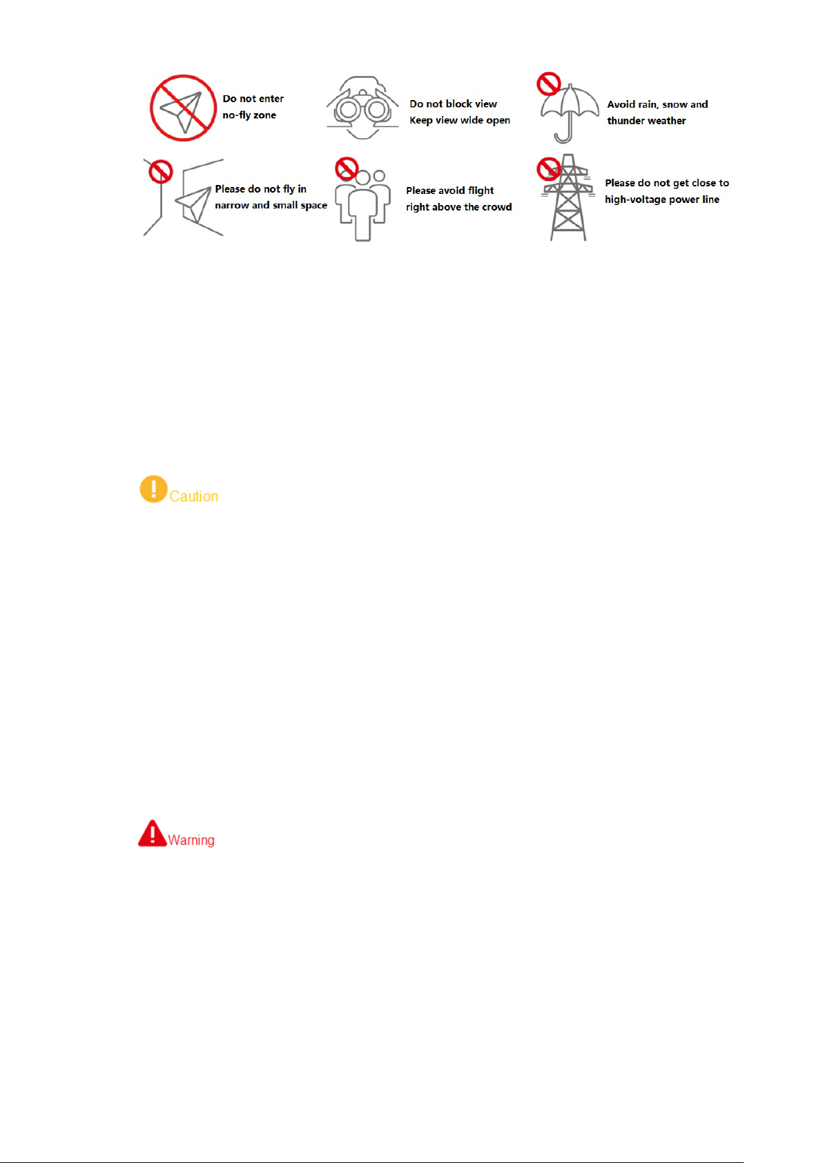
Keep away from no-fly z one; ple as e do not enter no-fly zone.
Keep view wide open; make sure the device is flying within field of view; please do not
block field of view.
Please do not fly the aircraft in rain, snow and thunder weather.
Please do not fly in narrow and small space.
Try not to fly r ight above the crowd, in order to prevent per sonal injury.
Please do not get close to high-voltage power line. Keep more than 10m distance.
Power Requirement
The product shall use electric wires (power wires) recommended by this area, which shall
be used within its rated specifi cat ion!
Products with category I structure shall be connected to grid power output socket, which is
equipped with protectiv e gr ounding.
Please conform to local elec t r ica l safety standards strictly.
Before operation, please c heck whether power supply is correct .
Please use power supply that meets SELV (safety extra low voltage) requirements, and
supply power with rate d voltage t hat conf orms to L imited Pow er Sourc e in IEC60 950-1. For
specific power supply requirements, please refer to device l abels.
Prevent power cord from being trampl ed or pr essed , especial ly t he plug, powe r socket and
the junction extruded from t he device.
Battery Points of Attention
It has to use the exclusive power adapter provided by Dahua Technology to charge the
device. Otherwise, it may damage the battery or lead to other unpredictable
consequences.
Charge the device at a temperat ur e between 0 and 50℃.
Distinguish positive and negative poles when charging the device, to prevent short circuit.
Charge and discharge at least once every month; prohibit storing the device without
electricity.
Please do not place the device cl ose to fire source or inflammables.
Please do not charge and dischar ge the device in unattended conditions.
Please do not use undesignated battery to the device.
VI
Page 8

Please do not dismantle and destroy the batt ery without per mission; w ater is not allowe d to
enter the device; man-made damages are not covered by w arr anty .
Please do not throw the bat t er y into fire or expose it to high-temperat ur e environment.
Please do not dismantle, modi fy or deform the battery.
Avoid short circuit between positive and negative contacts (please do not place the bat t er y
together with the objects such as necklace and hairpin etc. when carrying or storing the
battery).
Please replace new battery timely when it is damaged. Please contact local relevant
agency to deal with dama ged bat t er y properly, in order to prevent accidents.
Please charge the battery or discharge it to 50%~60% remaining capacity if it won 't be
used for a long time, and plac e it in a dry and cool environment.
If the battery leaks and the liquid enters eyes accidentally, please do not rub your eyes;
wash your eyes with clean water and see a doctor immediately.
It is normal that the battery heats up after it is running for a period of time, because the
discharge power is quite big.
It is normal that the battery heats up when it is being charged.
The cycle times of power bat t er y is 300 in normal application situation.
During charging of power batt ery, charging is completed when the charger displays “FULL”
and beeps continuously. Don’t take down batteries before charging is comp le t ed.
Application Environment Requirements
Please do not aim the PTZ at str ong l ight ( such as lighting, sunlight and so on).
Please transport, use and store the device within the allowed humidity and temperature
range.
Please do not let any liquid flow into the device.
Please do not block the device ventilation.
Please do not press, vibrat e or soak the device.
Please pack the device wit h or igi nal package or material with equivale nt quality.
Operation and Maintenance Re quirements
Please do not dismantle the dev ice privately.
Please do not touch sensor CCD or CMOS directly; use hair drier to remove dust or dirt
from the lens surface.
Please use soft dry cloth o r clea n soft c loth to d ip a li ttle mil d deterg ent t o clean t he device.
Please do not touch or wipe the lens surface directly.
Please use the accessor ies pr ov ided by manu factur er and it sha ll be i nstal led and rep air ed
by professional staf f s.
Please avoid laser beam radi at ion t o t he surface when using laser bea m dev ic e.
Please do not provide two or more power supply modes to the device at the same time;
otherwise, it may damage the device.
Max 1 aircraft is allowed to fly in t he same area at the same time.
VII
Page 9

Please make sure that there is no occlusion above the flight.
Special Announcement
This manual is for referen ce only. Please refer to the actual product for more details.
The user’s manual, software and firmware will be regularly updated according to the
product upgrade without p r ior announcement.
The user shall undertake any losses resulting from violation of guidance in the document.
The document may include technically inaccurate contents, inconsistencies with product
functions and operations, or misprint. Final explanations of the company shall prevail.
Interface in this manual may be slightly different from actual interface. Please refer to
actual interface for details.
Other trademarks or company names mentioned in the document belong to the respective
owners.
VIII
Page 10

Table of Contents
Legal Statement ......................................................................................................................................... I
Preface ....................................................................................................................................................... II
Important Safe guards and Warnings ..................................................................................................... V
1 Product Introduction ............................................................................................................................. 1
1.1 Overview ....................................................................................................................................... 1
1.2 Functional Features ...................................................................................................................... 1
2 Structure ................................................................................................................................................. 4
2.1 Aircraft ........................................................................................................................................... 4
2.1.1 Product Dimensions............................................................................................................ 4
2.1.2 Structural Component ......................................................................................................... 6
2.2 Airborne Device............................................................................................................................. 7
2.2.1 The 2 MP Visible Light PTZ Camer a .................................................................................. 8
2.2.2 Structural Compo nent of 2 MP Visible Light PTZ Camera ............................................... 10
2.3 Remote Control ............................................................................................................................ 11
2.3.1 Dimensions ........................................................................................................................ 11
2.3.2 Structural Component ....................................................................................................... 12
2.3.3 Buttons .............................................................................................................................. 16
2.3.4 Operation Interface ........................................................................................................... 18
3 Flight Prepar at ion ................................................................................................................................ 27
3.1 Unpack ........................................................................................................................................ 27
3.2 Check Remaining Power ............................................................................................................ 27
3.2.1 Aircraft ............................................................................................................................... 28
3.2.2 Remote Control ................................................................................................................. 29
3.3 Charging ...................................................................................................................................... 30
3.3.1 Aircraft Battery Charging .................................................................................................. 30
3.3.2 Remote Control Charging ................................................................................................. 31
3.4 Prepare Airborne Device ............................................................................................................. 31
3.4.1 Demount PTZ Camera ..................................................................................................... 32
3.4.2 Install PTZ Camera ........................................................................................................... 32
3.5 Prepare Aircraft ........................................................................................................................... 33
3.5.1 Unfold Arm ........................................................................................................................ 33
3.5.2 Open Antenna ................................................................................................................... 33
3.5.3 Install Aircraft Battery ....................................................................................................... 34
3.6 Prepare Remote Control ............................................................................................................. 34
3.6.1 Install Micro SD Card ........................................................................................................ 34
3.6.2 Open Antenna ................................................................................................................... 35
3.6.3 Enable Remote Control Power ......................................................................................... 35
3.6.4 Confirm Remote Control Mod e ......................................................................................... 36
3.6.5 Set Quick Operation ......................................................................................................... 36
3.7 Enable Aircraft Power ................................................................................................................. 42
3.8 Check and Debugging ................................................................................................................ 42
IX
Page 11

3.8.1 Remote Control Ca libr at ion .............................................................................................. 43
3.8.2 Accelerometer Calibration ................................................................................................ 43
3.8.3 Initialization Failure ........................................................................................................... 44
3.8.4 Geomagnetic Abnormity ................................................................................................... 45
3.8.5 GPS Satellites Insufficiency .............................................................................................. 47
3.9 Install Propellers.......................................................................................................................... 47
4 Enable Flight ........................................................................................................................................ 49
4.1 Flight Mode ................................................................................................................................. 49
4.2 Manual Mode .............................................................................................................................. 50
4.2.1 Introduction to Manual Flight Flow ................................................................................... 50
4.2.2 Unlock Flight Control ........................................................................................................ 50
4.2.3 Manual Takeoff ................................................................................................................. 51
4.2.4 Manual Flight Control ....................................................................................................... 52
4.2.5 Manual RTH and Landing ................................................................................................. 53
4.2.6 Manual Locking ................................................................................................................. 54
4.3 Intelligent Mode ........................................................................................................................... 55
4.3.1 Intelligent Flight Mo de ...................................................................................................... 55
4.3.2 Intelligent Locking M ode ................................................................................................... 59
4.3.3 Intelligent Operati on.......................................................................................................... 60
4.4 Intelligent Protection Mechanism ................................................................................................ 62
4.4.1 Low Battery ....................................................................................................................... 62
4.4.2 Out of Control ................................................................................................................... 62
4.5 Remote Control Setting ............................................................................................................... 62
4.5.1 Remote Button User-defined ............................................................................................ 62
4.5.2 Flight Control Settings ...................................................................................................... 63
4.5.3 Preview Settings ............................................................................................................... 66
4.5.4 Camera Settings ............................................................................................................... 67
4.5.5 General Settings ............................................................................................................... 70
5 End Flight ............................................................................................................................................. 75
5.1 Turn off Power ............................................................................................................................. 75
5.2 Remove Aircraft Battery .............................................................................................................. 76
5.3 Dismantle Airborne Device ......................................................................................................... 77
5.4 Fold Aircraft ................................................................................................................................. 77
5.5 Copy Video of Camera Micro SD Card ....................................................................................... 79
5.6 Remove Other Component s ....................................................................................................... 79
6 Upgrade and Update......................................................................................................................... 80
6.1 Firmware Update......................................................................................................................... 80
6.2 Remote Control Update .............................................................................................................. 80
6.2.1 APP Update ...................................................................................................................... 80
6.2.2 Download and Upda t e O ffline Map of Remote Contro l .................................................... 81
Main Techni cal Parameters ............................................................................................. 82
Aircraft State Indicator ................................................................................................... 85
System Pairing .................................................................................................................. 87
FAQ .................................................................................................................................... 89
Appendix 4.1 FAQ and Solutio ns of Aircraft ..................................................................................... 89
Appendix 4.2 FAQ and Solutio ns of Remote Control ....................................................................... 89
Appendix 4.3 FAQ and Solutio ns of Airborne Device ....................................................................... 89
X
Page 12

Appendix 4.4 FAQ and Solutions of Charger .................................................................................... 89
XI
Page 13

1.1 Overview
This product is a hex-rotor drone d esi gned f or pub lic security, transportation, firefighting, border
defense, agriculture, forest and energy source fields. It provides integrated solutions of aerial
video surveillance.
This product consists of air cr aft, airborne device and remote control.
Aircraft: It consists of navi gat ion system, flight control system a nd power system.
Airborne device: It consists of the PTZ control system and mission device.
Remote control: It consists of the remote control system, data chain and software.
1 Product Introduction
1.2 Functional Feat ures
Integrated Design
The aircraft adopts integrated design and neat appearance. Only the propeller shall be
dismantled and installed.
The remote control integrates the remote control and touch screen together. It is easy to
operate and has clear indicator.
Folded Packages
Arm can be folded repeatedly.
Antennas can be folded repeat edly, suitable to be carried, transported and stored.
Quick Dismantling
The propeller adopts quick dismantling structure.
It is easy to open or fold arm and antenna.
The PTZ camera adopts quick dismantling structure. Installation screws are secured on
the shock absorber plate, in order t o pr event them from being lost.
HD Video
The shock absorber board and shock absorber ball work together to guarantee PTZ
Industrial 30x optical zoom visible light camera is optional, with professional HD video
camera stability.
1
Page 14

effect.
IR thermal camera is opt ional, su itab le for sp eci al en v ironments su ch as fire s cene or night
environment, so as to guar ant ee clear video and high restoration t hermal images.
The remote control has snapshot button and record button, which are easy to operate and
instantly start snapshot an d r ecor d f unc tion.
Accurate Positioning
Built-in GSP system ensures that positioning is accurate and real-time.
Wireless Transmission
Aircraft has 4 antennas. Connect the remote control and image transmission device to
send and receive radio wave signals.
The remote control has 3 antennas. Connect the aircraft to send and receive radio wave
signals.
Low Electric Quantity Protection
When electric quantity is lower than estimated safe return value, trigger low electric quantity
protection automatically, including alarm, return home and landing.
Intelligent Battery
Display remaining electr ic quantity: Battery has built-in power i ndicator light.
Balanced charging protection function: Automatically balance the battery cell voltage to
protect battery.
Overcharge protection function: Battery automatically stops charging when the voltage is
full.
Sleep protection function: Battery automatically goes to sleep state when there is no
operation within 5 minutes .
Charging temperature pro t ection fun ction: Th e batt er y c harging te mperat ure r ange s from 0 ℃
to 50℃. Once the temperature is too high, bat ter y automat ical ly st ops chargin g; other wise,
it may result in battery damage.
Communication: The r emote control can get remaining capacity and voltage information.
Flight Control
The aircraft adopts hex-rotor power system. It can switch among several flight modes and
control the flight direction flexibly.
Support 14,500g maximu m take-off weight.
Support binocular obstacl e avoidance, optical flow positioning, R TK and protection in case
of broken propeller.
Electronic Fence (e-fence)
Support e-fence functio n; pr event the aircraft from leaving the specified flight zone.
2
Page 15

Support customized e-f ence settings.
3
Page 16
2 Structure
This product mainly consists of aircraft, airborne device and remote control. This chapter
introduces the structures of these 3 components. The detailed operations will be introduced in
“3 Flight Preparation”.
All figures listed below and all dimensions listed here for reference only. The figure and the
dimensions may be slightly different from the user data due to measurement position,
measurement accuracy and position indication. Please refer to the actual product for detailed
information.
2.1 Aircraft
This section is introduced when the propeller is installed completely and the whole device is
unfolded. Please refer to Cha pt er 3 for details.
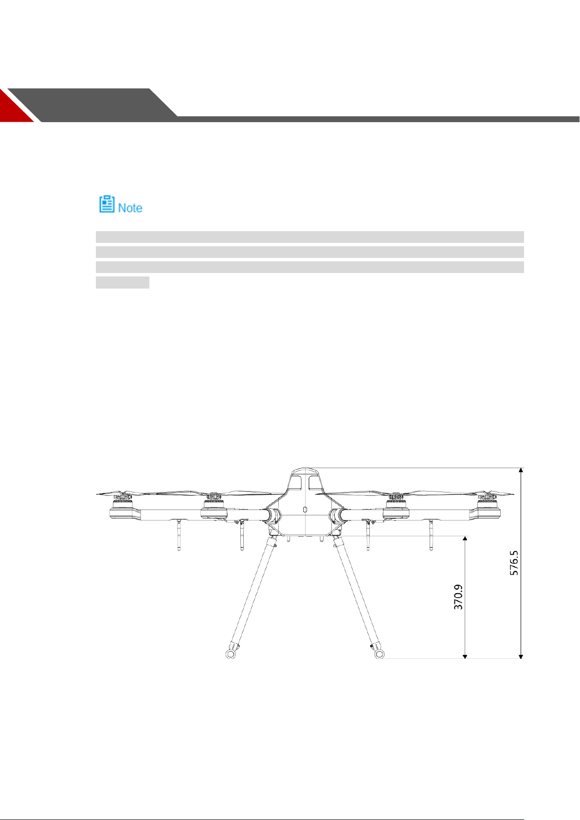
2.1.1 Product Dimensions
Unit is mm.
Figure 2-1
4
Page 17
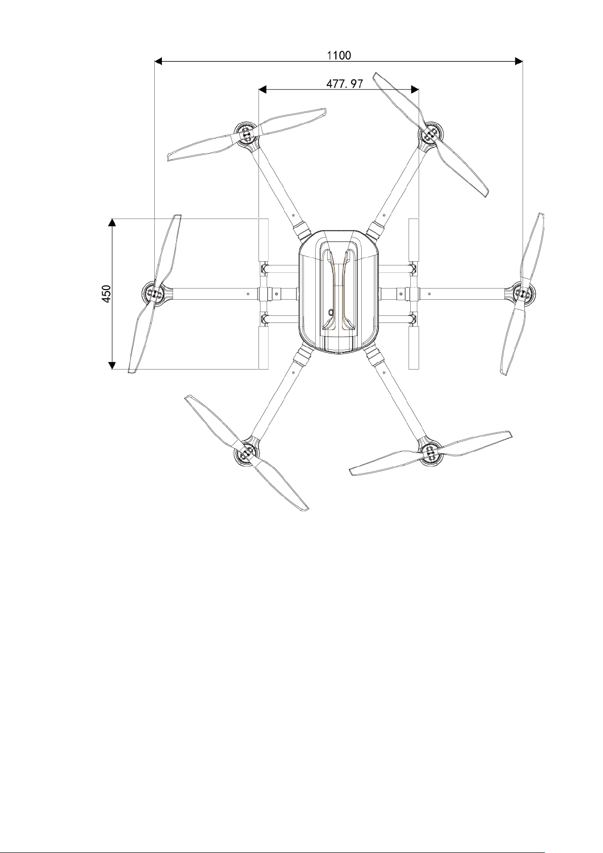
Figure 2-2
5
Page 18
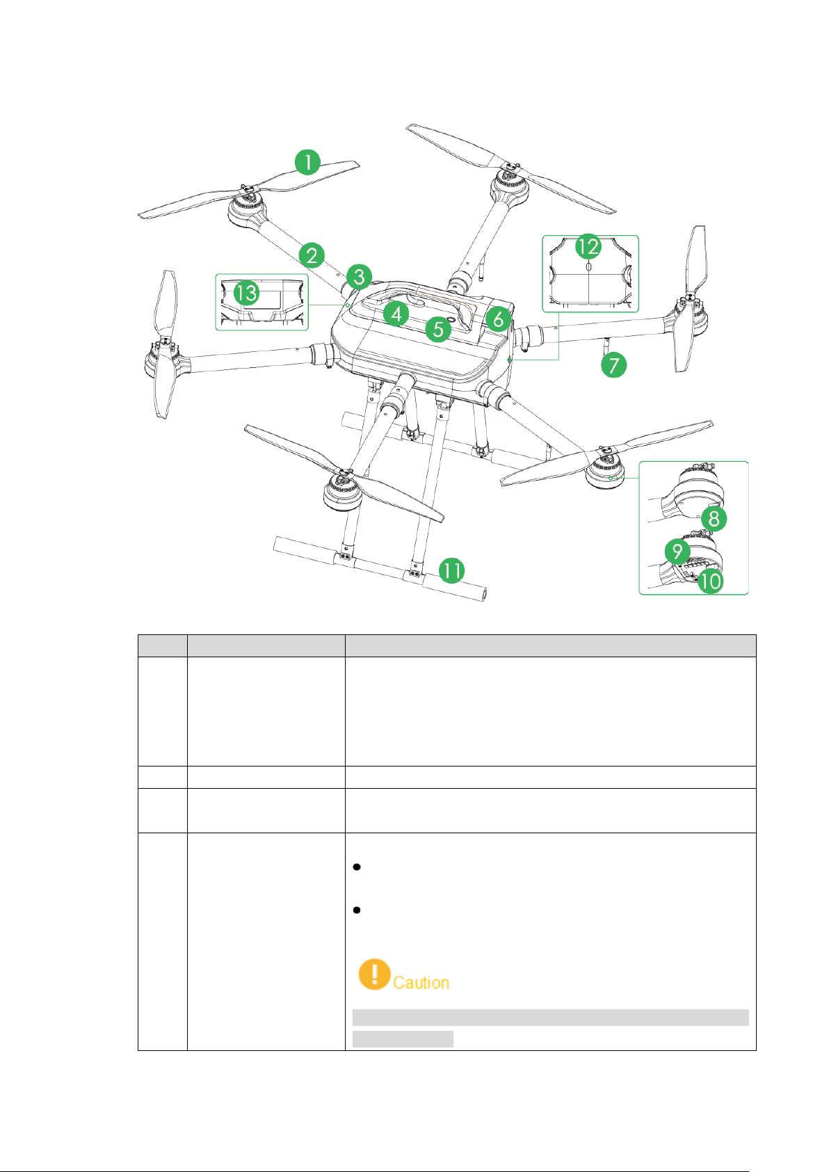
2.1.2 Structural Component
No.
Name
Function
according to the actual sit uat ion.
2
Arm
Fold and unfold.
Protective cover of
After the battery is installed into the aircraft, battery buckle
shall be closed!
1 Propeller
3
4 Battery buckle
propeller
Figure 2-3
High-speed revolution to turn the brushless motor power to
propulsive force.
There are 3 pairs of propellers (3 CW propellers and 3 CCW
propellers) with different structures. Please install propellers
Fix the horizontally unfolded arm.
Dismantle and install the battery.
When it is opened, battery can be dismantled from the
device and replaced.
When it i s c l ose d , the battery cannot be dismantled from
the device.
6
Page 19
No.
Name
Function
switch (with
Built-in indicator.
middle part indicates aircraft tail.
Motor speed
controller
With sine wave driving, have excellent acceleration and
deceleration performance.
Control the landing gear to open or fold with remote control
There are two modes: normally on and flashing. It displays
five colors: red, yellow, blue, green and purple, to indicate
er to Appendix 2 for indicator light information and
definition.
Heat dissipation
Built-in binocular heat dissipation module (cooli ng f in).
This module has different structures depending on device
configurations. Pleas e refer to actual product.
5
Power
indicator)
After the aircraft is power on, red indicates power-on state,
while green indicates re m ain ing battery.
6 Empennage Built-in GPS and elect r onic compass.
Fold or unfold.
7 Antenna
2 antennas are to receive the r em ot e cont r ol signal.
2 antennas are for wireless image transmission.
Display red and green.
Two adjacent indicators are normally on in red; their
middle part indicates aircraft nose.
Four adjacent indicators are normally on in green; their
8
Motor control panel
indicator
9 Motor Drive propeller rotation.
10
11 Landing gear
buttons.
12 Aircraft state indicator
13
module (cooling fin)
2.2 Airborne Devic e
system state, flight mode, upgrade state and et c.
Ref
Table 2-1
This part takes visible light PTZ camera and IR thermal PTZ camera as an example, and
introduces airborne devic e.
For detailed info about various airborne device, please refer to their user’s manual s and
quick start guides.
The aircraft supports to carry 2 MP visible light PTZ camera and multiple airborne devices.
7
Page 20
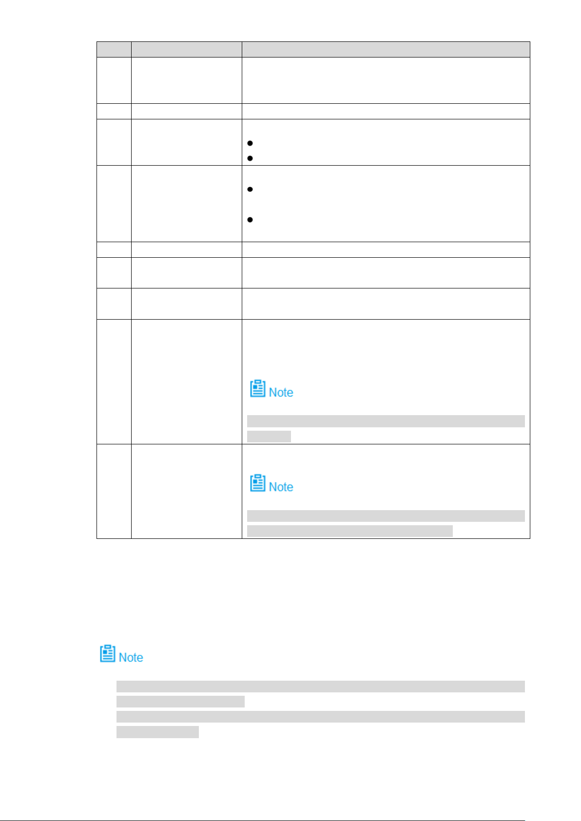
2.2.1 The 2 MP Visible Light PTZ Camera
Unit is mm.
Figure 2-4
8
Page 21
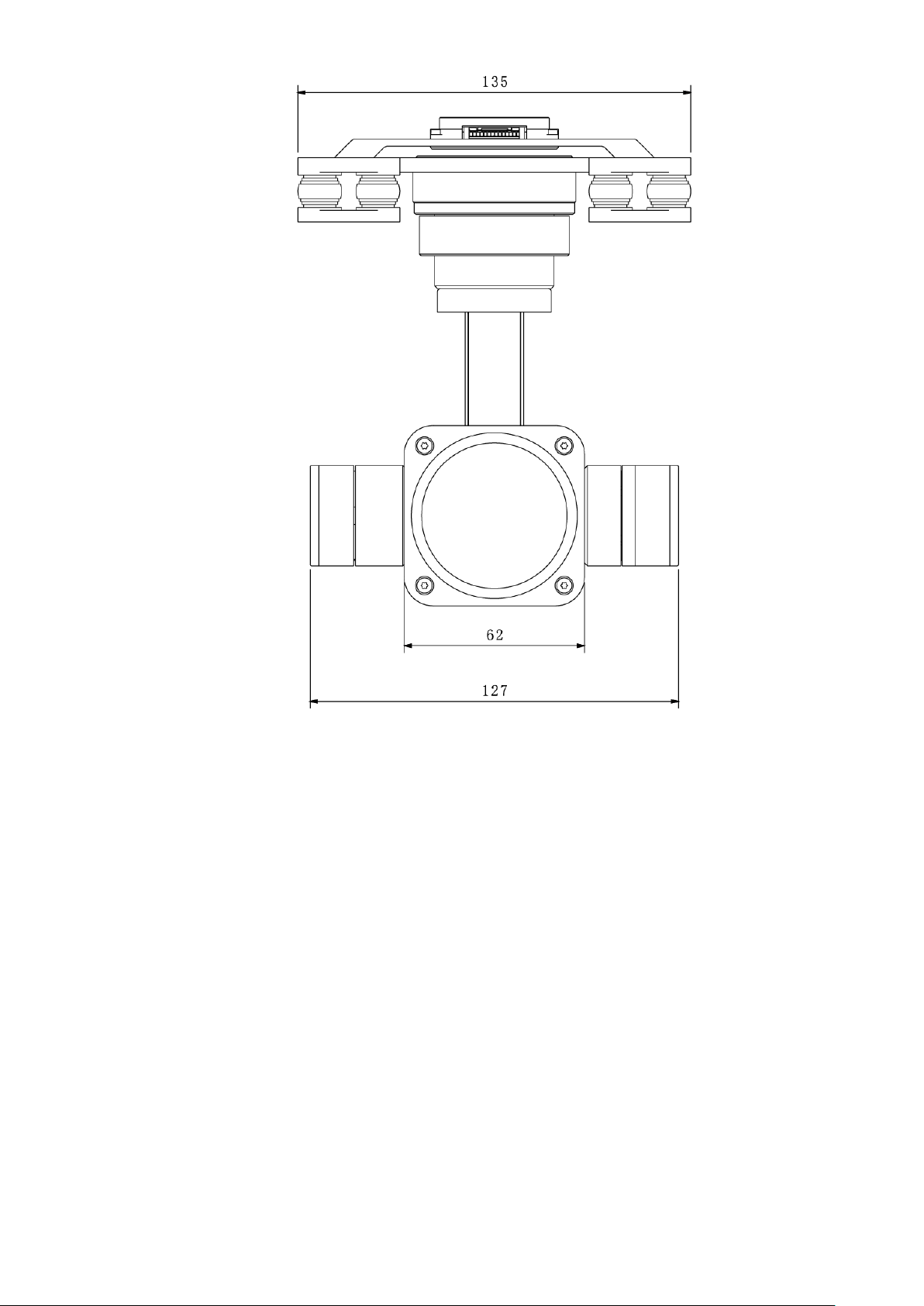
Figure 2-5
9
Page 22
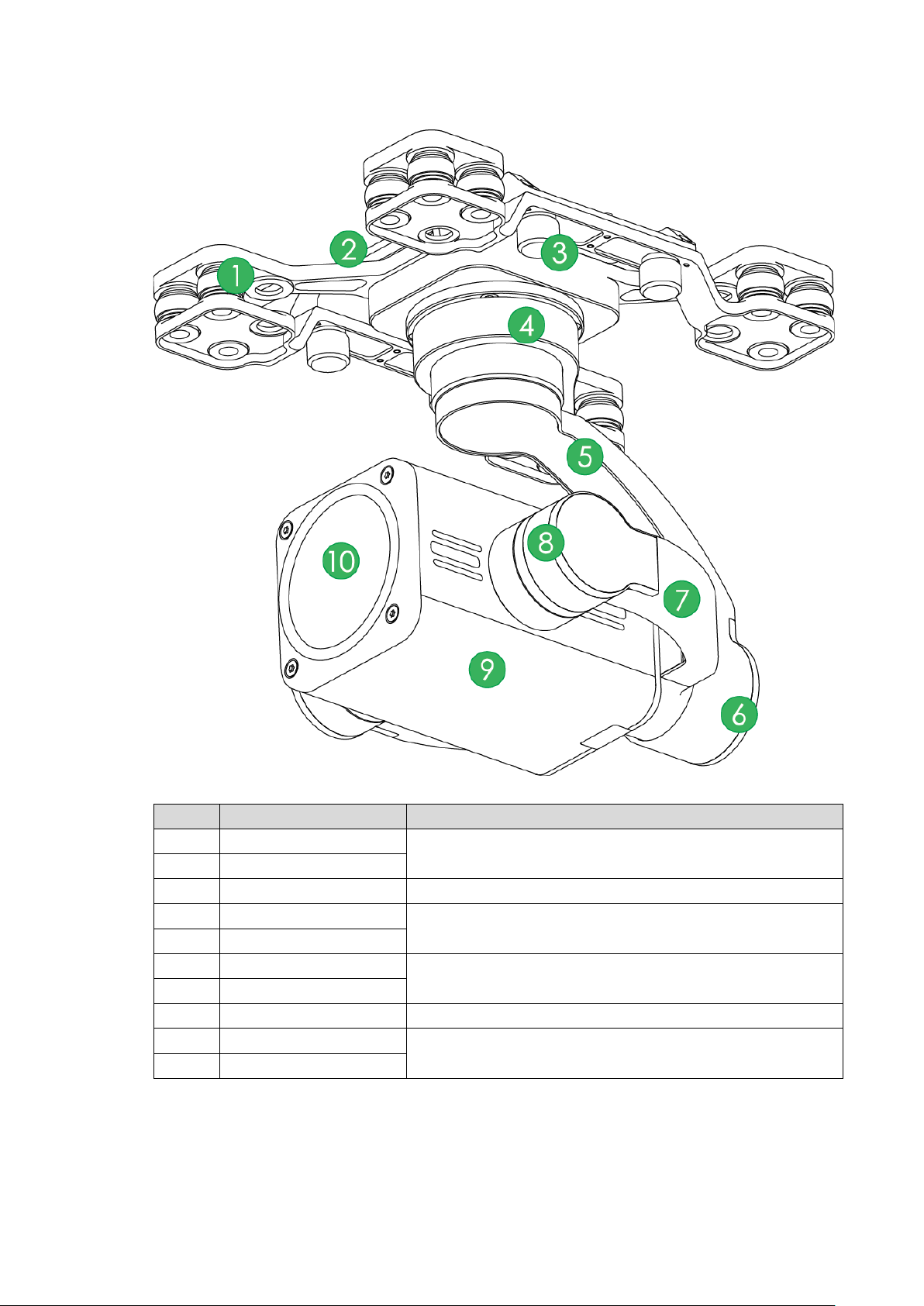
No.
Name
Function
1
Shock absorber ball
Reduce PTZ camera vibration during the flight, to get
2
Shock absorber board
3
Installation screw
Secure the PTZ camera on t he aircr aft.
4
Course motor
2.2.2 Structural Component of 2 MP Visible Light PTZ Camera
Figure 2-6
clearer video.
Control horizontal directi on of the camera.
5 Course rotation arm
6 Roll motor
Control horizontal inclination angle of the camera.
7 Roll rotation arm
8 Pitching motor Control vertical pitching angle of the camera.
9 Camera
Take pictures.
10 Lens
Table 2-2
10
Page 23
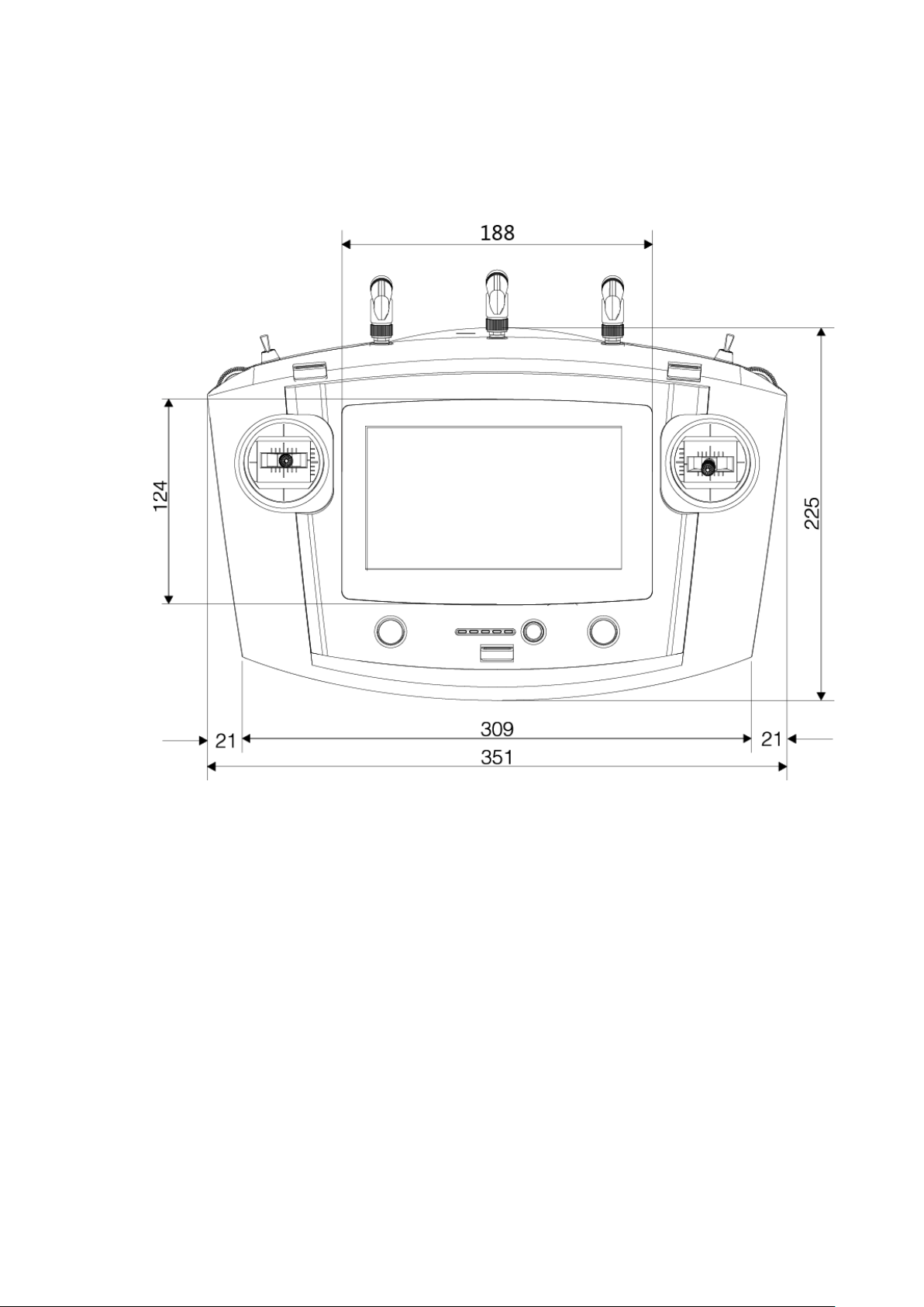
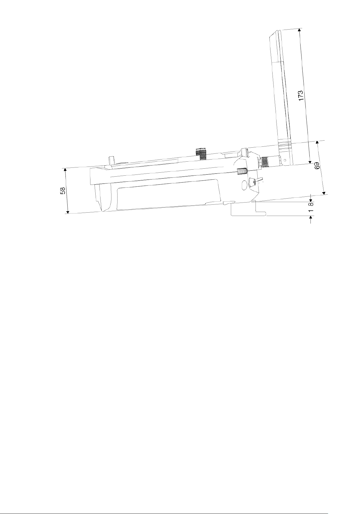
2.3 Remote Control
2.3.1 Dimensions
Unit is mm.
Figure 2-7
11
Page 24
2.3.2 Structural Component
Front panel, side panel and rear panel of the remote control are shown in Figure 2-9, Figure
2-10 and Figure 2-11.
Figure 2-8
12
Page 25
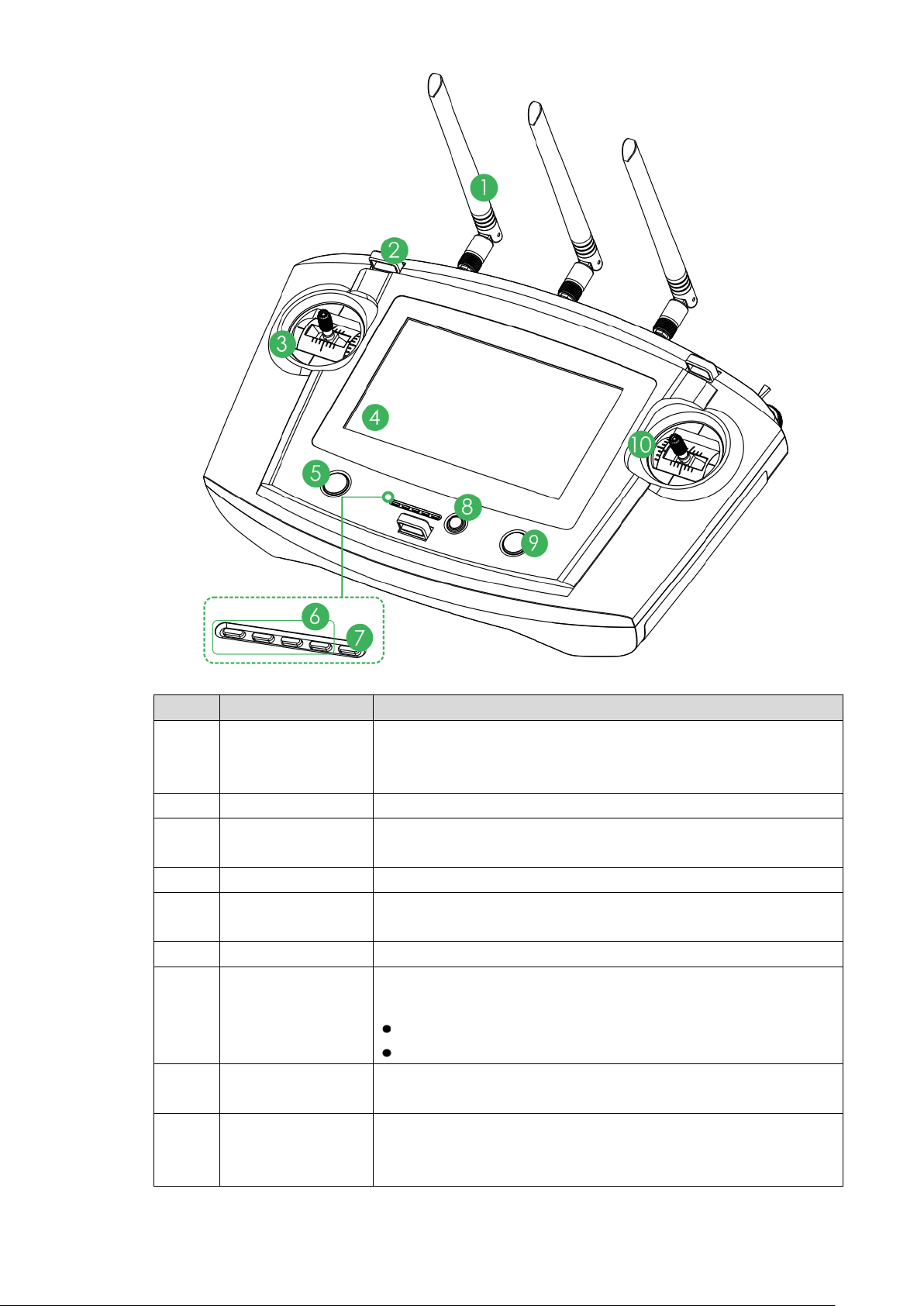
No.
Name
Function
while two yellow antennas are installed at both sides.
2
Hanger
Fix the hanger belt.
Left control
Landing gear
connecting power to the charging
click return
button
Figure 2-9
Establish the remote control relationship with the aircraft and
1 Antenna
3
joystick
receive images. One silver antenna is installed in the middle,
Control the aircraft flight state.
4 Touch screen Set parameters and preview the video.
5
button
Control the landing gear.
6 Battery indicator Each bar represents 25% bat t er y power.
Indicator light is on when
7 Charging indicator
8
One-
port.
Red light is normally on: chargi ng.
Green light is normally on: charging is finished.
Control aircraft to return h om e aut omatically.
9
One-click
takeoff/landing
button
Control aircraft takeoff or landing with one click. Takeoff height
is 2m.
13
Page 26
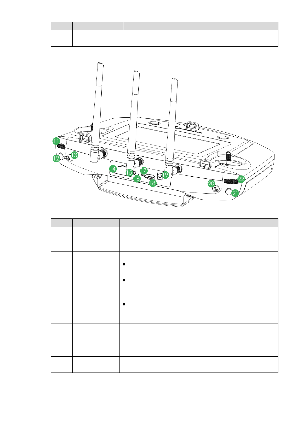
No.
Name
Function
Right control
No.
Name
Function
Upper level: intelligent flight mode. The aircraft flights
are at the central mode, the aircraft hovers at the same
Reset button of
PC.
10
joystick
Control the aircraft flight state.
Table 2-3
Figure 2-10
11
PTZ course scroll
wheel
Control horizontal shooti ng angle of camera lens.
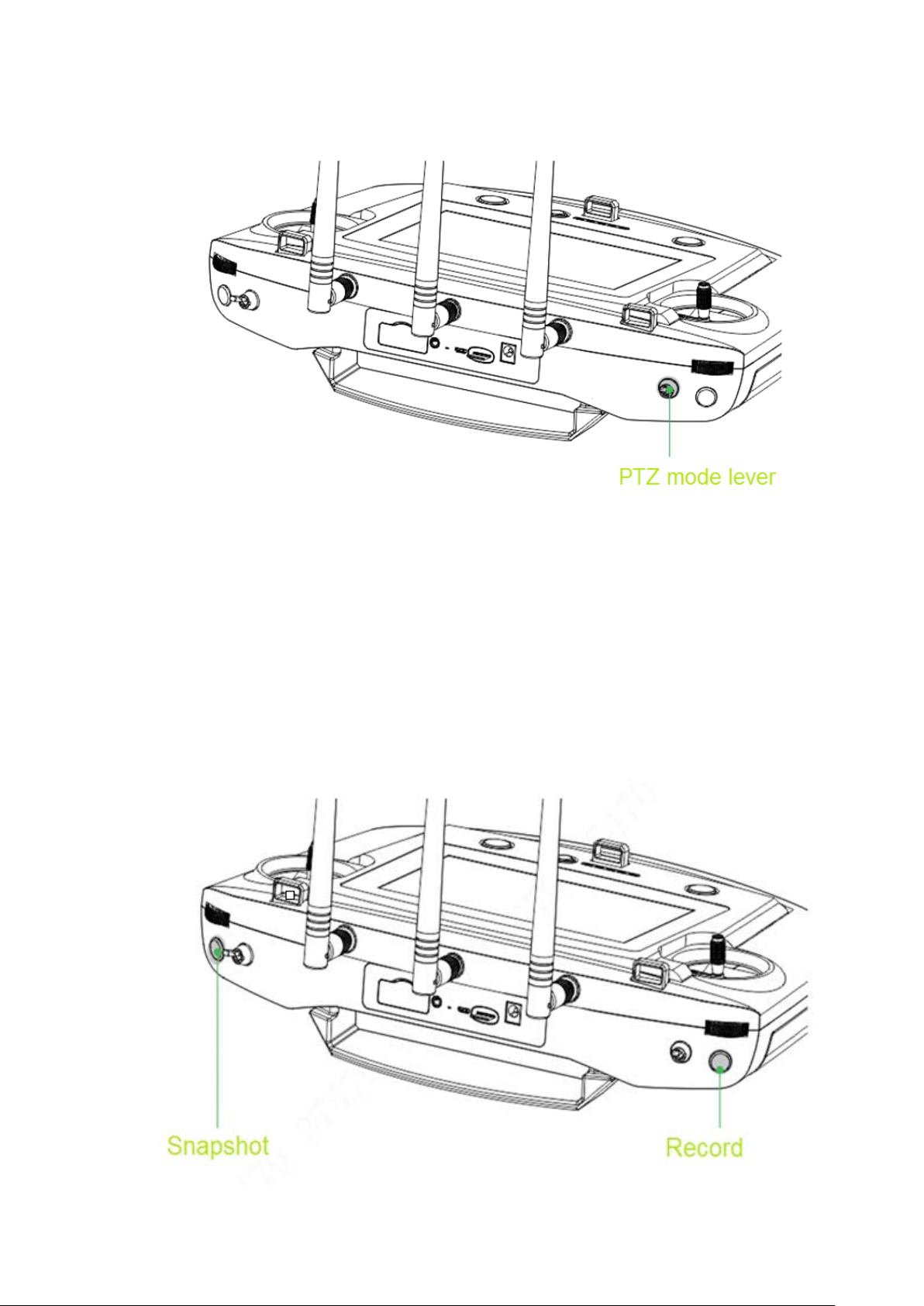
12 Snapshot Press this button shortly to snapshot present image.
3-level lever to select flight mode.
automatically accordin g t o the specified course.
Middle level: flight at the specified height. When the throttle
13 Flight mode lever
lever is at the central mode, the aircraft flights at the same
height automatically.
Lower level: flight at the specified position. When all levers
position.
14 4G SIM slot Support 4G function.
15 Audio output port Connect to earphone, sou nd box and etc. It is to play audio.
16
remote control
17 Micro USB port
Reserved.
Insert data cable to connect PC. It is to transmit the data to the
14
Page 27
No.
Name
Function
18 SD slot
Insert micro SD card: The micro SD card with the chip is
micro SD card pops up a little bit, and can be pulled out.
19
Power port
Input DC 12V power.
2-level lever. It is to select PTZ mode.
Lower level: Course locking mode. No matter what the
same degree to shoot.
Press this button shortly to start recording, and press it again to
PTZ pitch scroll
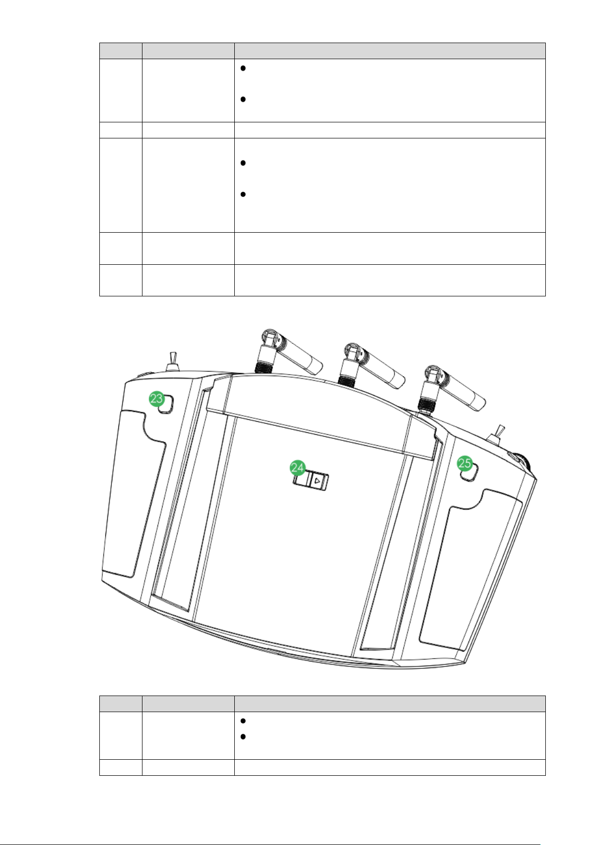
No.
Name
Function
Press it for a short time, to zoom in the camera.
the maximum magnification.
24
Power switch
Turn on or tur n off the remote control.
20 PTZ mode lever
facing down. Insert the ca r d t o t he slot hor iz ontally.
Remove micro SD card: Press micro SD card inwards, so
Upper level: Course follow ing mode. The PT Z ca mera angl e
changes with aircraft flight direction.
aircraft flight angles are, the PTZ camera always faces the
21 Record button
22
wheel
stop recording.
Control vertical shooting a ngle of camera lens.
Table 2-4
Figure 2-11
23 Zoom in button
Press it for a long time, to zoom in until the camera reaches
15
Page 28
No.
Name
Function
25 Zoom out button
Press it for a short time, to zoom out the camera.
Press it for a long time, to zoom out until the camera
2.3.3 Buttons
Refer to Chapter 4 for the joystick and flight mode lever butt on infor m at io n.
2.3.3.1 Scroll Wheel
reaches the minimum magnification.
Table 2-5
Besides “PTZ Course Scroll Wheel” and “PTZ Pitching Scroll Wheel” of remote control, control
PTZ “PZT Center” and “PTZ 90°” through “State Bar > Quick Operation > PTZ”. Please refer to
“3.6.5.2 PTZ” for details.
PTZ course scroll wheel: control horizontal shooting angle of camera lens, as shown in
Figure 2-12.
Scroll wheel turns to the left: PT Z t ur ns t o the left.
Scroll wheel turns to the right: PTZ turns to the right.
Figure 2-12
PTZ pitching scroll wheel: control vertical shooting angle of camera lens, as shown in
Figure 2-13.
Scroll wheel turns to the left: camera lens turns downwards.
Scroll wheel turns to the right: camera lens turns upwards.
Figure 2-13
16
Page 29
2.3.3.2 PTZ Mode Lever
Shooting direction of PTZ camera is controlled with PTZ mod e lever, as shown in Figure 2-14.
2-level lever:
Upper level: Course following mode. Shooting angle of PTZ camera changes with aircraft
flight direction.
Lower l evel: Course locking mode. No matter what the aircraft flight angles are, the PTZ
camera always faces the same degree to shoot.
Lever returns to the center: start from any position, move the lever for three times
continuously. Shooting angle o f P TZ camera will be consistent with a ircr aft flight direction.
2.3.3.3 Shooting
Figure 2-14
Figure 2-15
17
Page 30
Snapshot: Press snapshot button for a short time to snapshot t he pr esent image.
No.
Name
Function
Function setting
list, flight mode, remote control signal intensity, GPS signal
Quickly switch video preview and map preview to display
Display remaining flight time, aircraft speed, height and
Bar” for details.
Record: Press record button for a short time to begin recording video. Press it for a short
time again to stop recording.
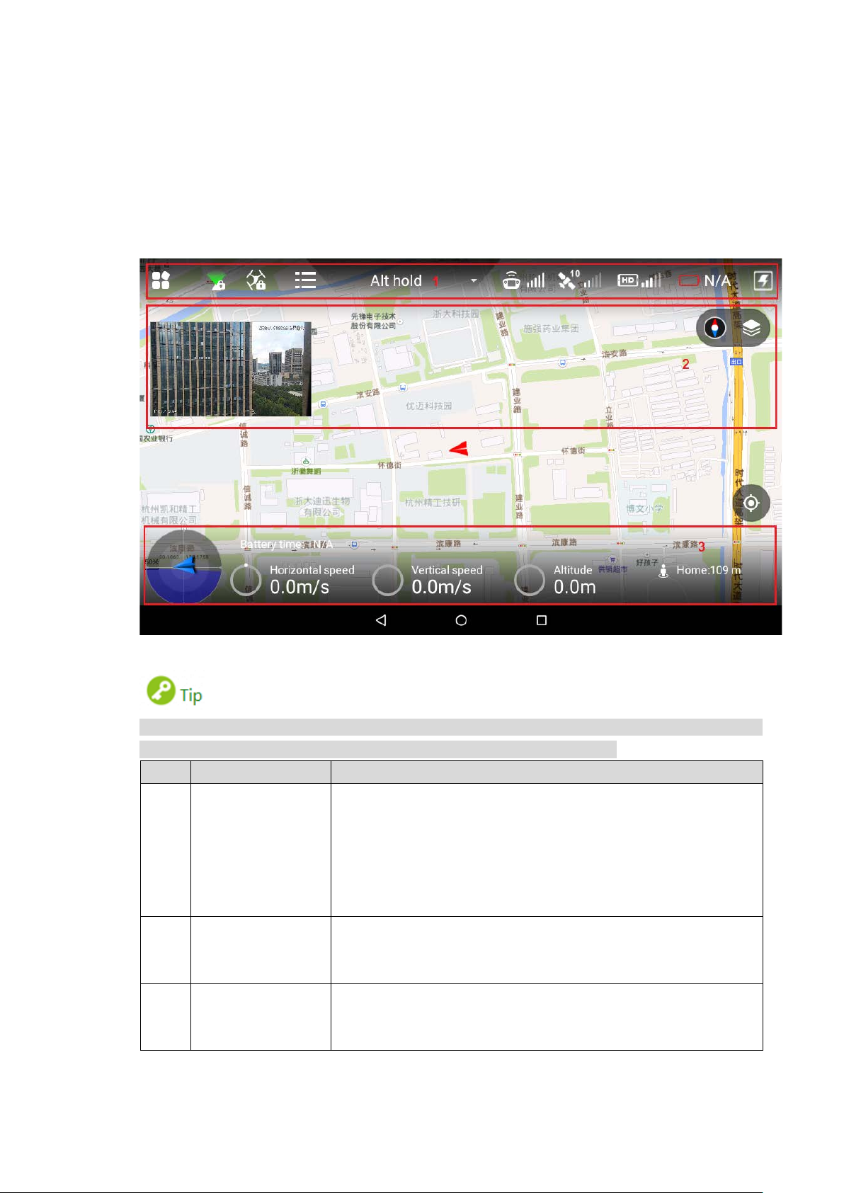
2.3.4 Operation Interface
After turning on with the remote control, enter main interface. It consists of the following
function modules, as sho w n in Figure 2-16.
Figure 2-16
Slide up at any positio n on the prev iew inter face to h ide the s etting m enu, funct ion bar and state
bar. Slide down at any position on the main inter f ace to view them again.
Set the menu and aircraft course; d isplay PTZ mode, flight state
1
and state bar
intensity, image transmission signal quality, aircraft battery and
quick viewing.
Please refer to “4.5 Remote Control Setting” for spec i fi c set ti ng
items and descriptions.
2 Preview window
prompt information and PTZ control. Please refer to “2.3.4.3
Preview” for details.
3 State bar
distance from the HOME. Please refer to “2.3.4.2 State Display
Table 2-6
18
Page 31

2.3.4.1 Function Setting and State Bar
Icon
Name
Function
Click this icon to enter sett ing me nu.
Display present PTZ mode (PTZ locking or PTZ
the PTZ camera has locked the course
the PTZ camera direction is flight following
mode. The shooting angle changes with the
Click this icon to set aircraft course locking or return
Please refer to “2.3.4.1.2 Locking Mode” for details.
Click this icon, and aircraft state list will pop up.
remaining/total capacity info.
Flight mode
Remote control
GPS satellite
and signal
Remaining
battery of
aircraft
Display battery info of the aircraft.
Display N/A when the aircraft is not connected;
display present aircraft battery percentage after
Figure 2-17
Settings
Please refer to “2.3.4.1.1 Setting” for details.
following mode).
: When the PTZ lever is at the lower level,
direction. No matter how aircraft angle changes,
PTZ mode
the PTZ camera is still fac ing t he same direction
to shoot.
: When the PTZ lever is at the upper level,
aircraft course angle.
Locking mode
locking mode.
Drone state list
display
signal intensity
intensity
Image
transmission
signal qua lity
View compass, accelerometer, gyro, remote mode,
GPS signal, drone battery and camera SD card
Display present flight mode of the aircraft, including
intelligent flight, loiter an d fix ed point mode.
Display signal intensity of remote co ntrol a nd aircra ft.
There are max. 5 bars. The more the highlighted bar
amount is, the stronger the remote control effect is.
The number on the left side is the GPS satellite
amount.
The GPS signal intensity is shown on the right.
There are max. 5 bars. The more t he highlight ed
bar amount is, the stronger the remote control
effect is.
Click this icon, and imag e transmission signal quality
frame will pop up. Display general signal quality of
image transmission antenna.
19
Page 32

Icon
Name
Function
pairing connection.
Click this icon to enter quick entry interface, and set
and other quick
for details.
Level 1 Menu
Level 2 Menu
Level 3 Menu
Function
Manual Flight
calibration
Remote Control
Calibration” for details.
Pair the remote control and aircr aft again.
Appendix 3 System
function of the
Remote Button
User-defined” for details.
Select fence action.
for details.
Max height
Set max. height, max. radius and reach
distance
Image
settings
Set preview image size.
for details.
2.3.4.1.1 Setting
Click to enter setting interface, as shown in Table 2-8.
Remote
Control
Quick operation
Control
joystick mode
Remote
control
Remote pair -
Remote
button
user-defined
dashboard, PTZ, image transfer
options. Please refer to “3.6.5 Set Quick Operation”
Table 2-7
Provide two modes.
-
Please refer to “4.2.4
Control” for details.
Calibrate the remote contr ol.
-
Please refer to “3.8.1
Please refer to “
Pairing” for details.
Indicate A1 button and
-
remote control.
Please refer to “4.5.1
Fence enable -
Flight
Fence
settings
Preview
transmission
Camera Photo settings -
Fence type
Fence action
Max radius
Reach
-
Enable or disable e-fence.
Please refer to “4.5.2.2 Enable Electronic
Fence” for details.
Set e-fence type.
Please refer to “4.5.2.1.1 Fence Type” for
details.
Please refer to “4.5.2.1.2 Fence Action”
distance of the fence.
Please refer to “4.5.2.1.3 Other Settings”
for details.
Please refer to “4.5.3 Preview Settings”
Set photo size.
Please refer to “4.5.4.1 Photo Settings”
for details.
20
Page 33

Level 1 Menu
Level 2 Menu
Level 3 Menu
Function
Set relevant parameters o f video.
Set brightness, contrast, saturation,
for details.
Check firmware status and upgrade.
Calibrate geomagnetism.
Abnormity” for details.
Download and
for details.
Set networking mode.
Settings” for details.
Micro SD
version
General
Video settings -
Advanced
Aircraft
firmware
upgrade
APP upgrade -
Other
Image
settings
-
Geomagnetic
calibration
Acceleromete
r calibration
Offline map
Brightness
Date and time
Please refer to “4.5.4.2 Video Sett ings” for
details.
sharpness and gamma v alue.
Please refer to “4.5.4.3 Image Settings”
Please refer to “6.1 Firmware Update” for
details.
Check APP status and upgrade.
Please refer to “6.2.1 APP Update” for
details.
Please refer to “3.8.4 Geomagnetic
Calibrate accelerometer.
Please refer to “3.8.2 Accelerometer
Calibration” for details.
Add or delete offline ma p.
Please refer to “6.2.2
Update Offline Map of Remote Control”
for details.
Adjust brightness of tablet PC.
Please refer to “4.5.5.1.3 Brightness” for
details.
Set the date and time of remote cont rol.
Please refer to “4.5.5.1.4 Date and time”
About
On settings interface, clic k to return to the previous menu and click to exit settings.
Network
setting
Language
Storage
setting
Hardware
Table 2-8
Please refer to “4.5.5.1.1 Network
Set software language of rem ot e cont r ol.
Please refer to “4.5.5.1.5 Language” for
details.
View total storage space o f Micro S D card
and the space occupied b y every part.
Please refer to “4.5.5.1.2
Settings” for details.
Display hardware info.
21
Page 34

2.3.4.1.2 Locking Mode
Click it to select locking mode of the aircraft on the popped up dialog box, as shown in Figure
2-18.
2.3.4.1.3 Flight State List
Click the icon to display dr one st ate list, as shown in Figure 2-19.
Figure 2-18
View drone state info in a real-time way.
2.3.4.1.4 Quick Operation
Realize quick setting of dashboard, PTZ, image transfer and others. Please refer to “3.6.5 Set
Quick Operation” for details.
Click the icon to display quick operation, as shown in Figure 2-20.
Figure 2-19
22
Page 35

Icon
Name
Function
Aircraft direction
and camera lens
Blue triangle: it indicates the aircraft
Display remaining flight time of the aircraft.
N/A when the aircraft is not
Actual flight time may be affected by
2.3.4.2 State Display Bar
direction
Figure 2-20
Figure 2-21
direction on the geographi c pos ition.
Battery time
It displays
connected.
This estimated value is for reference only.
enviroment and etc., so it may be different
from the actual flight time.
23
Page 36

Icon
Name
Function
Horizontal forward and backward speed of
Vertical ascending and descending speed
of the aircraft. It displays N/A when the
displays N/A when the aircraft is not
connected.
Distance from the
Distance between the airc r aft and Home.
2.3.4.3 Preview
Click the window at the top left corn er, to switch b etw een vide o prev iew mode and map prev ie w
mode.
Prompt information is displayed on the right side of the icon. Click the icon to view
message list.
Horizontal speed
the aircraft. It displays N/A when the aircra ft
is not connected.
Vert ical speed
aircraft is not connected.
Relative altitude from the takeoff position. It
Altitude
HOME
This value is planar project ion dis t ance.
Table 2-9
2.3.4.3.1 Video Preview Mode
Default preview mode is show n in Figure 2-22.
In this mode, the map is displayed in a small window at the top left corner of the preview
interface.
In this mode, the large window displays the real-time image transmitted by the camera to
the remote control.
Figure 2-22
24
Page 37

2.3.4.3.2 Map Preview Mode
In this mode, the image transmitted by the camera to the remote control is displayed in a
small window at the top left corner of the preview interface.
In this mode, the large win dow displays aircraft position on the ma p.
Buttons in map preview mode ar e described as follows:
Map direction locking button: W hen it is unlocked, press the map interface with two
fingers to rotate the map; w hen it is locked, map direction cannot be changed.
Map display mode switching button: Switch to displa y the map in the form of satellite
imagery or 2D image.
Central button: Switch to current position of the aircraft quickly and center at current
position of the aircraft.
2.3.4.4 General Functions
Figure 2-23
2.3.4.4.1 Set Home Point
Click the icon to set current location of the aircraft to be Home, as sh ow n in Figure 2-24.
Figure 2-24
25
Page 38

2.3.4.4.2 Locking Mode
Click the icon to select locking mode of the aircraft on the popped up dialog box, as shown in
Figure 2-25.
Figure 2-25
26
Page 39

This chapter elaborates com plete flow before the aircraft is unlocked and takes off.
Start flight
Please select operation according to the actual situation after the first flight is over, if it is
Please operate by strictly conforming to the steps described in this chapter; the operation
sequence can't be revers ed.
Flight
Preparation
Phase
3 Flight Preparation
not the used for the first time.
Unpack
↓
Chec k remai ni ng power →Please charge in ca se of low battery
↓ ↙
Prepare airborne device
↓
Prepare aircraft
↓
Prepare remote control
↓
Enable aircraft power
↓
Chec k debugging →All debugging is normal
↓ ↙
Figure 3-1
3.1 Unpack
Take out aircraft, battery, propellers and rem ote control from the packing box.
3.2 Check Remaining Power
Check the remaining power of aircraft battery and remote control. Implement the subsequent
steps after confirming that the battery reaches the standard.
27
Page 40

Please refer to “3.3 Charging” when the battery is low. Please implement the sebsequent steps
5
●●○○~●
○○
50%~37.5%
6
●◎○○
●○○○
37.5%~25%
7
●○○○
○○○
25%~12.5%
8
○○○
○○○○
12.5%~0
after charging.
3.2.1 Aircraft
3.2.1.1 Aircraft Battery Check
Short press the aircraft batt ery switch and check the state of indicator lights, as shown in Figure
3-2.
Battery switch has 5 indicator light states. The front red indicator light means that the battery is
on, whereas the other 4 green indi cator lights represent remaining power of the battery.
At normal temperature, the remaining power shall be ≥2.
The aircraft shall take off with full power when temperatur e is l ow er than -10℃.
3.2.1.2 Aircraft Remaining Power
There are three states for each indicat or light of the aircraft batt ery, which are normally on, flash
and off.
The following table describes remaining power percentage in different status. “●” means
normally on, “◎” means flash and “○” means off, as shown in Table 3-1.
No. Indicator Light Status Remaining Battery Perce ntage Range
1 ●●●●~●●●◎ 100%~87.5%
2 ●●●◎~●●●○ 87.5%~75%
3 ●●●○~●●◎○ 75%~62.5%
4 ●●◎○~●●○○ 62.5%~50%
◎
~
~◎
◎
~
Figure 3-2
Table 3-1
28
Page 41

3.2.2 Remote Control
No.
Indicator Lig ht St a t us
Remaining Battery Percentage Range
3
○○●●
○○○●
50%~25%
4
○○○●
○○○○
25%~0
3.2.2.1 Remote Control Battery Check
Move the power switch to the arr ow location; view the number of indicator l ights which are on.
Figure 3-3
Figure 3-4
At normal temperature, t he remaining power shall be ≥2.
Remaining power shall be ≥3 when the temperature is lower than -10℃.
3.2.2.2 Remaining Power of Remote Control
There are two statuses for each indicator light of remote contr ol, w hich are normally on and off.
The following table describes remaining power percentage in different status, “●” means
normally on and “○” means off, as shown in Table 3-2。
1 ●●●●~○●●● 100%~75%
2 ○●●●~○○●● 75%~50%
~
~
Table 3-2
29
Page 42

3.3 Charging
It doesn't need to implement t he following chapter if the remaining pow er is e nough.
3.3.1 Aircraft Battery Charging
During charging of pow er battery, charging is completed when the charger displays “FULL” and
beeps. Don’t take down batt er ies before charging is completed.
The entire charging period (from 0 to full) is about 2 hours. Charging period is related with
remaining power and char gin g cur r ent .
Figure 3-5
Take out the battery: open battery switch, and li ft the battery vertically to take it out.
Connect AC: connect charger power wire with charger por t , and connect A C p ower.
Connect DC: insert charging adapter cable into battery and char ger por t .
Select char ging mod e: open charg er switch, turn the black butt on, select BL C and shor t
press the black button. The value displayed by LED nixie t ube bounces and flashes.
Select char ging curre nt: tur n the button to adj ust curr ent, whos e propose d value is 20 A.
After adjustment, short press the black button to confirm.
Open the battery: short press the battery indicator light button once, and then long
press it for 3 seconds, to turn on the electric quantity indicator light and check present
battery.
Long press the button to start charging and wait for the charger prompt. It means
charging is completed when t he char ger beeps for 5 times and LED nixie tube displays
FULL.
30
Page 43

Figure 3-6
After charging is completed, disconnect it from the power socket, and then press stop
button on the charger to turn off the charger.
3.3.2 Remote Control Charging
The entire charging period (from 0 to full) needs approximately 3. 5 hour s.
Please charge the remote c ont r ol when its power is off.
Connect DC: connect the remote control and pow er adapt er with a charging cable.
Figure 3-7
Connect A C: connect power adapter with AC power (AC 100V- AC 240V).
Check char ging state: it means t he remote c ontrol is charging w hen the indicator light is
red and normally on. It me ans ch arging is do ne whe n the in dicat or light beco mes gree n
and normally on, as shown in
Disconnect it from the po wer soc ket, and then d isconne ct other cabl es a fter charg ing is
completed.
Figure 3-8.
Figure 3-8
3.4 Prepare Airbor ne Device
The following chapter is o ptional for operation. It is for y our referen ce when air borne dev ice
shall be replaced.
This chapter introduces operation of airborne device with PTZ camera as an example.
31
Page 44

Please refer to actual product .
Please implement demounting step first and then connection step when the PTZ camera
needs to be replaced.
It only needs to implement demounting step when the aircraft flies directly without PTZ
camera.
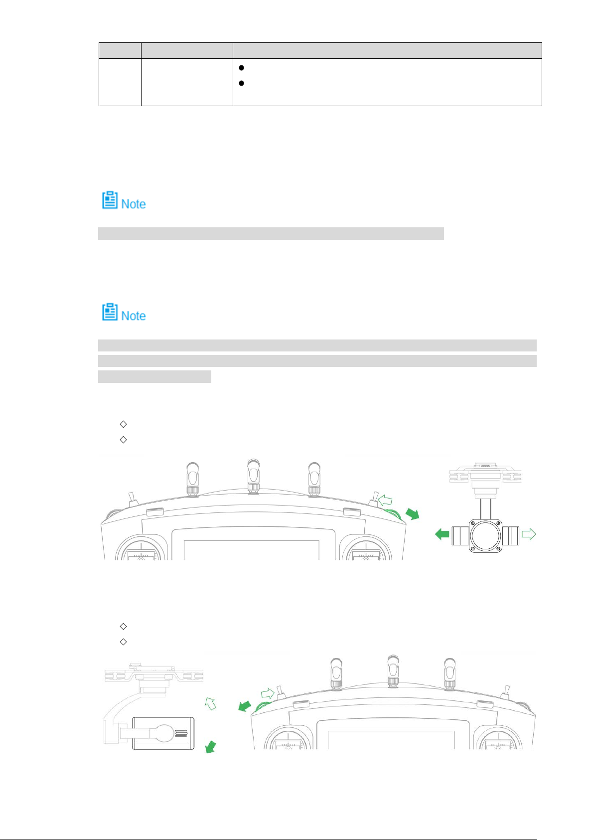
3.4.1 Demount PTZ Camera
Loosen 4 mou nt in g s cr ews, as shown in Figure 3-9.
Take down PTZ camera.
3.4.2 Install PTZ Camera
Insert the upper port on the vibration damper plate of the PTZ camera into
corresponding port at t he bot t om of t he aircraft, as shown in
Figure 3-9
Figure 3-10.
Figure 3-10
Align 4 mount ing screw s with t he hole positi ons at the bott om of the air craft, and t ighten
the screws.
32
Page 45

3.5 Prepare Aircraft
3.5.1 Unfold Arm
Unfold the arm to horizont al posit ion. Hold the ar m with le ft hand, an d tighte n helical cas ing with
right hand, so as to fix the arm hor izontally, as shown in Figure 3-11.
The subsequent steps can be implemented only when the arm is fixed horizontally. Please
contact our company if the arm is lo ose.
3.5.2 Open Antenna
It is recommended to unfold the antenna to vertical position, in order to realize optimum
communication eff ec t .
Unfold the aircraft antenna, move it to vertical position and make it firmly stuck, as shown in
Figure 3-12.
Figure 3-11
Figure 3-12
33
Page 46

3.5.3 Install Aircraft Battery
After battery has been installed, battery buckle shall be fixed. Then, the aircraft can be
moved with battery handle.
If battery buckle is not fixed, t he aircr aft will fall off.
Open the batt er y buckle, as shown in Figure 3-13.
Figure 3-13
Put the batt ery into battery compartment horiz ont ally, as shown in Figure 3-14.
Figure 3-14
Close the battery buckle, and aircraft batt er y installation has been completed .
3.6 Prepare Remote Control
3.6.1 Install Micro SD Card
Remote control owns about 3G memory space. Please choose and install micro SD Card
according to actual needs.
34
Page 47

The following chapter is option al for oper ati on. It is for your reference when th e user need s
to install micro SD card.
Micro SD card needs to be configured on your own.
Micro SD card supports m ax . 16G.
Make the metal surface of micro SD card face downward and insert it into the micro SD card
slot of the remote control side panel horizontally.
3.6.2 Open Antenna
Open the antenna of remot e cont r ol to pr oper location, as shown in Figure 3-16.
Figure 3-15
Figure 3-16
3.6.3 Enable Remote Control Power
Please skip the chapter if t he pow er is not turned off after checki ng r emaining battery.
Enable remote control power: move the power button of remote contro l to the arrow location, as
shown in Figure 3-17.
35
Page 48

Figure 3-17
3.6.4 Confirm Remote Control Mode
It is mode 2 by default. Please set in “Settings > RC Set t ings > Joystick Mode” to switch mode,
as shown in Figure 3-18.
Please refer to “4.2.4 Manual Flight Control” for remote control mode and its corresponding
relations.
3.6.5 Set Quick Operation
Click at the upper right corner of main interface, set quick operation items of remote
control interface, view dashboard, and set PTZ, image transfer, flight task, flight path and stop
beep.
3.6.5.1 Dashboard
View parameters o f remote control dashboard.
Click “Dashboard”, and the system enters “Dashboard” interface, as shown in Figure 3-19.
Figure 3-18
36
Page 49

3.6.5.2 PTZ
Set the PTZ, such as PTZ positi on and throwing.
Figure 3-19
Click “PTZ”, and the system enters “PTZ” interface, as shown in Figure 3-20.
37
Page 50

Parameter
Note
Set param et er s according to actual needs. Please refer to Table 3-3 for details.
PTZ Mode View present mode of PTZ.
PTZ Position
Throwing Set throwing, including t hr ow ing device A and throwing device B.
Click key A on the r em ot e cont r ol, t o car r y out PTZ control.
3.6.5.3 Image Transfer
Set resolution ratio, frame rat e and m aximum bandwidth of preview ima ge according to needs.
Select “Image Trans fer”, and the system enters “Ima ge T ransf er” int er face, as show n in
Figure 3-21.
Figure 3-20
Set PTZ position, including PTZ 90 degrees and PTZ center.
PTZ 90 degrees: the cam era is vertically downward.
PTZ center: the camera lens faces the front .
Table 3-3
38
Page 51

Select reso lution ratio, frame rate a nd maxi mum bandw idth of prev iew image according
to actual needs.
3.6.5.4 Other
Set the flight task, flight path and stop beep here.
3.6.5.4.1 Fly Task
Set the flight task of remote control according to actual needs, including flight path and flight
time.
Select “Other > Flight T as k”.
The system displays “Flig ht Task” interface, as shown in Figure 3-22.
Figure 3-21
39
Page 52

Configur e f lig ht t ask according to actual needs.
Append: click this icon to enter waypoint setting interface, set waypoint flight task
Download: click this icon to download present saved flight path automatically.
Select: click this icon to select one task or multiple tasks, and delete the task.
3.6.5.4.2 Flight Data
Save and delete the flight pat h dat a of the aircraft.
Select “Other > Flight Data”.
The system displays “Flight Data” interface, as shown in Figure 3-23.
Figure 3-22
according to actual needs and save it.
Modify waypoint accordi ng to actual needs and save the task at remote control.
40
Page 53

Figure 3-23
Click “Edit”.
Select the flight path which shall be deleted and saved according to actual needs, as
shown in Figure 3-24.
Figure 3-24
Click “Complete” to complete flig ht data setting.
Click “Select All” to operate all flight data toget her.
41
Page 54

3.7 Enable Aircraft Power
After power on, when the remote control doesn’t require other operations, please always keep
the aircraft horizontal and s t at ic; ot her w ise, it may result in initialization fa ilure.
The battery is full if 4 indicator lig ht s ar e gr een.
Insert intelligent battery of the aircraft, short press power switch, and green indicator light
indicates present battery electricity, as shown in Figure 3-25.
3.8 Check and Debugging
The subsequent steps can be implemented only after checking and debugging all the items
listed in the chapter below. Besides, the remote control prompts that each state is normal and
the aircraft indicator light f lashes green.
It is recommended to set the display image of remote control as video preview mode before
taking off.
Check operation condition. Please debug each component to make it operate normally when
both remote control prompt s abnormity.
Figure 3-25
It is going to list common calibration items, abnormities and solutions in the following chapter.
42
Page 55

3.8.1 Remote Control Calibration
If it isn’t turned to maximum value end, it may not r espon d t o oper ation, operat ion is not smooth,
and the aircraft may even explode after calibration.
Select “Settings > Remote Control Sett ings> Joystick Calibration”.
The system displays “Joystick Calibration” interface, as show n in Figure 3-26.
Move bot h t he le ft and r i ght joysticks back to the middle.
Click “Start Calibration”.
Turn two joysticks and turn to the maximum value end of each direction for several
times.
Slide the r oll ing whee ls on bot h s ides, slide to the max imu m valu e en d of tw o direct ions
for several times.
Click “Complete Calibration” after turning the rolling wheels and joysticks.
After calibration, view “3.6.5.1 Dashboard“, and turn corresponding buttons to confirm if
calibration is successful. After successful calibration, each parameter is about 1514.
Turning the endpoint, maximum value is 19XX w hile minimum value is 10XX.
The remote control can be normally used about 30s after calibr at ion.
3.8.2 Accelerometer Calibration
Select “Settings > General > Other > Accelerometer Calibration” to enter “Accelerometer
Calibration” interface, as shown in Figure 3-27.
Figure 3-26
43
Page 56

Place the aircraft on a flat surface, and click “Start Calibration”.
The remote control will pr om pt “Calibration Success” if it is successfully calibrated.
The remote control will prompt “Calibration Failure” if it fails to calibrate. Click “Retry” till it
is successfully calibrated.
Pay attention to levelness and perp endicularity during calibration. Non-standard posture during
calibration will lead to abn or mal flight and even explosion.
3.8.3 Initialization Failure
Abnormity Prompt
Remote control prompts “I nitialization Failure”.
Figure 3-27
Possible Reasons
After power on and before taking of f, it may res ult in initializ atio n failure if you move the aircra ft.
Solutions
Power on the aircraft again after the power is cut off, and keep the aircraft horizontal and static
during initialization. Plea se contact our company if initial ization fails for several times.
44
Page 57

3.8.4 Geomagnetic Abnormity
Abnormity Prompt
Aircraft indicator ●●● flashes.
Remote control prompts “Geomagnetic Abnormity”.
Possible Reasons
The use position has changed a lot, which means the geographical location is quite far
away from the last geographical location where the aircraft is used, causing big change to
geomagnetic field.
There is another intensive magnetic field or abrupt change in the environment, affecting
geomagnetic field.
Solutions
Select “Settings > General > Other > Geomagnetic Calibration” on the remote control.
The system displays “G eomagnetic Calibration” interface, as shown in
Figure 3-28.
Figure 3-28
Click “Start Calibration”.
Keep the aircraft horizontal and rotate it for 360° horizontally, as shown in Figure 3-29.
45
Page 58

Figure 3-29
Keep the aircraft vertical and rotate it for 360° v er t ically, as shown in Figure 3-30.
Figure 3-30
46
Page 59

It will prompt geomagneti c calibration success if it is success ful ly calibrated.
It will prompt geomagnetic calibration failure if it fails to calibrate. Re peat St ep 2, 3
and 4 to calibrate again.
3.8.5 GPS Satellites Insufficiency
Abnormity Prompt
Displayed number of satel lites of remote control is less than 6.
GPS HDOP: at the top status bar of remote control is less than 1 bar or there is
no signal.
Possible Reasons
The flying environment is not w ide open enough, which is severely blocked.
There is some other interf erenc e around the surroundings.
Solutions
Move the aircraft to a wider area and w ait for 30s.
3.9 Install Propellers
Press the s pring buckle on both sides of the propell er cent er, as shown in Figure 3-31.
Figure 3-31
Buckle the latc h on the motor , as s how n in Figure 3-32.
Structures of 2 types of propellers are different. Adjust to the adjac ent m ot or position to
install if it fa ils to buckle.
47
Page 60

Figure 3-32
48
Page 61

4 Enable Flight
This chapter will elaborate t he com plete flow of formal takeoff and landing of the aircraft.
Please stay away from the rot at ing propellers or motor, to avoid personal injur y.
For your personal and property safety, please make sure to check the following items c ar ef ul ly
before enabling flight.
Flight preparations liste d i n Chapter 3 are all completed.
All the components have been c or r ectly and stably installed.
Make sure that each spare part is in good condition. Please do not fly the aircraft if some
parts are aged or damaged.
Flight environment meet s t he r equirements listed in important safeguards and warnings.
Please do not block the ventilat ion near heat dissipation hole wh en t he motor is operating.
Enable Flight
This chapter will introduce man ual and intelligent flight mode separ at ely.
Switch between these two modes. For example, you can use one-key takeoff and landing
buttons in the manual flight mode.
4.1 Flight Mode
Unlock
↓
Take off
↓
Flight
↓
RTH and Landing
↓
Lock
Figure 4-1
Control flight mode via dri ving lever during flight phase, as shown in Figure 4-2.
49
Page 62

Figure 4-2
Three-level driving lever :
Upper level: Intelligent flight mode. The aircraft will fly automatically according to the
pre-set flight route.
Medium level: It is the fixed height flight mode in manual flight mode. The aircraft will
maintain the current flight hei ght when the throttle joystick is in the middle.
Lower level: Fixed point flight mode in manual flight mode. The aircraft will maintain the
current location when all st icks are located in the middle.
4.2 Manual Mode
4.2.1 Introduction to Manual Flight Flow
Manual Unlock
Manual Takeoff (One Key Takeoff)
Manual Flight Mode
Manual RTH and Landing (One Key RTH and
4.2.2 Unlock Flight Control
Manual Flight Control
Landing)
Manual Lock (Auto Lock Av ailab le)
Figure 4-3
↓
↓
↓
↓
Move the left joystick to lower left, meanwhile move the right joystick to lower right (or move the
left joystick to lower right, meanwhile move the right joystick to lower left), and keep the status
for 2s. At this moment, the propellers are unlocked and start to rotate. Move all the sticks back
to middle, as shown in Figure 4-4.
50
Page 63

If there is obvious dif feren ce about r otating spe ed of t he propellers , move t he left joystick to
lower left and meanwhile move the right joystick to lower right (or move the left joystick to
lower right, and meanwhile move the right joystick to lower left), and then keep the status
till the propellers stop rota t ing. Turn of f the aircraft and contact our company.
The aircraft will be automatically locked if it stays on the ground and doesn’t take off within
10s after it is unlocked.
4.2.3 Manual Takeoff
Slightly push the throttle to m id-point or higher, as shown in Figure 4-5.
Figure 4-4
51
Page 64

Figure 4-5
4.2.4 Manual Flight Control
Set remote control mode and control flight direction of the air cr aft.
Figure 4-6
The joystick presets two remote contr ol modes.
It is mode 2 by default. Please modify in “Settings > Remote Control Settings > Joystick Mode”
to switch to mode 1.
Mode 1:
Vertical direction of left joystick is pitching joystick, which controls the ai rcraft to go
forward and backward hor iz ont ally.
Horizontal direction of left joystick is course joystick, which controls the aircraft to
52
Page 65

make left and right turn horizontally.
Vertical direction of right joystick is throttle joystick, which controls the aircraft to
ascend and descend.
Horizontal direction of right joystick is rolling joystick, which controls the aircraft to
move left and right horizontally.
Figure 4-7
Mode 2:
Moving the left joystick up and down (throttle joystick) to control aircraft’s ascending
and descending.
Moving the left joystick left and right (course joystick) to control aircraft’s left and right
turn horizontally.
Moving the right joystick up and down (pit ching joystic k) to contro l aircraft’s f orward
and backward movement hor iz ontally.
Moving the right joystick left and right ( r olling joy st ick) to control aircraft’s left and right
movement horizontally.
Figure 4-8
4.2.5 Manual RTH and Landing
Manual RTH: Control the aircraft to hover over a proper land ing p oint.
Manual landing: Reduce the throttle to make the aircraft land slowly.
53
Page 66

Figure 4-9
4.2.6 Manual Locking
Move the left joystick to lower left and move the right joystick to l ow er r ight at the same time (or
move the left joystick to low er r ight and move the right joystick to lower left at t he same time).
Figure 4-10
54
Page 67

4.3 Intelligent Mode
4.3.1 Intelligent Flight Mode
Intelligent flight mode incl udes w aypoints and circle around point of interest.
Waypoints flight: Set waypoint flight mission according to requirements. Move the flight
mode joystick at right rear of remote control to intelligent mode after the aircraft takes off,
select proper flight mission and click “Start Mission”.
Circle (around point of interest) flight: Set circle flight mission according to requirements.
Move the flight mode joystick at right rear of remote control to intelligent mode after the
aircraft takes off, select proper flight mission and cl i c k “Start Mission”.
When the flight mode joystick of remote control is moved to any mode (point, elevation or
intelligent mode), you can set waypoint flight or circle flight and save flight mission.
The aircraft is allowed to implement flight mission only when the flight mode joystick of
remote control is moved t o t he int elligent mode (Mode F).
It can realize waypoint flight or point of interest circle flight only after the aircraft takes off,
and it can't be realized on the ground.
Click the button on the main interface of the remote control, and enter the interface of
intelligent flight mode, as shown in Figure 4-11.
Figure 4-11
55
Page 68

4.3.1.1 Waypoints
Select “Waypoints”.
The system displays “Waypoints” interface, as shown in Figure 4-12.
Check total route length, est imated flight t ime a nd set “Cy cle Flight” at the bottom of the
interface.
Figure 4-12
Click the map and the position can be set as a waypoint; several waypoints can be
connected together and fo r m a rout e.
Check total route length, estimated f light time and se t “Cycle Flight ” at the bottom of the
interface.
Click a waypoint and it will become red. Waypoint setting interface will display on the
right of the interface, as shown in
Figure 4-13.
56
Page 69

Parameter
Note
Altitude
Set flight altitude of waypoint.
Speed
Set flight speed of waypoi nt
Latitude and
Automatically acquire latitude and longitude of the waypoint when
Shutter: it will take photos after the aircraft arrives at the way point.
Action cycle setting is invalid when the waypoint action selects “No
input time. The aircraft
Figure 4-13
Set way point parameters. Please refer to Table 4-1 for mor e det ails.
Head orientation Set head orientation of waypoint according to requirement dur ing flight.
Residence time Set hovering time after the aircr aft reaches a waypoint.
adding the waypoint.
longitude
Manually set waypoint latitude and longitude. Waypoint position will
skip to manual setting poi nt after setting is done.
Waypoint action
No action: it is not to set way point ac t i on.
Action”.
When waypoint action selects “Shutter”,
Action cycle
arrives at the waypoint an d it w ill ta k e a phot o after a period of time.
Note
Action cycle shall be less than or equal to residence time.
Table 4-1
Click “Save” to make configuration valid.
Click to set waypoint parameters in batches. Meanwhile, it can modify or delete
several waypoints.
Click to input mission name, click “Save” and you can check saved flight missions
57
Page 70

4.3.1.2 Circle
Select “Circle”.
in the list.
Click to enter flight mission interface. There are three operations:
Add mission: Click the icon to enter waypoint setting interface, set waypoint flight
mission and save it accor din g to actual requirements.
Download mission: Click the icon to automatically download the currently saved
flight route. You can modify t he waypoint accord ing to actual require ment and sav e
it into the remote control.
Select mission: Click the icon, select one or more missions on the interface, and
delete the mission(s).
The system displays “Circle” interface, as shown in Figure 4-14.
Figure 4-14
Click the m ap and the position can be set as intere st point.
Click the inter est po int, and the point icon will become red. Settings int erf ace of interest
point will be displayed on the right of main interface, as shown in
Figure 4-15.
58
Page 71

Parameter
Note
Speed
Set flight speed of interest point.
optional.
Set the para m et er s of interest point. Please refer to Table 4-2 for mor e det ails.
Altitude Set flight altitude of interest point.
Cycle radius Set flight radius of aircraft flying around interest point.
Cycle mode
Click “Save” to make configuration valid.
Set one interest point only for each flight mission.
Click to input mission name, click “Save” to save flight mission.
Select the flight direction of aircraft flying around interest point, clockwise
4.3.2 Intelligent Locking Mode
Figure 4-15
Table 4-2
Click and it will pop out a dial og box . Sel ect lockin g mode of the air craf t.
59
Page 72

There are two types of intelligent locking modes, namely cours e lock and return lock.
Course lock: Click it to lock the present head direction as its forward direction.
During the following flight process, the aircraft course has nothing to do with the
head direction; the aircraft will always move forward according to the locked head
direction.
Return lock: Click it and the aircraft course has nothing to do with the head
direction. Always take the straight line direction far away from HOME point as
forward direction and the straight line direction close to HOME point as backward
direction.
If both modes are canceled: the aircraft head direction is forward direction.
Click “Return Lock” and the icon becomes yellow, and it will prompt “Return Lock
Enabled”.
Click “Course Lock” and the icon becomes yellow, and it will prompt “Course Lock
Enabled”.
4.3.3 Intelligent Operation
Figure 4-16
4.3.3.1 Auto Takeoff
In fixed point mode, first unlock flight control, and then short press the takeoff and landing
button on the front panel of the remote control. The aircraft will ta ke off automatically and begin
flight according to the pre-set route.
60
Page 73

4.3.3.2 Auto RTH and Landing
The landing under the condition of low battery or in the uncontrollable situation has been
introduced in other chapters; this chapter will only introduce the landing modes in other
situations.
Figure 4-17
Short press RTH button on the front panel of the remote control, and the aircraft will return to
Home.
4.3.3.3 One-key Landing
Under the present condition, the aircraft needs to land vertical ly.
Short press the takeoff and landing button on the front panel of the remote control, and the
aircraft will land at the curr ent position automatically.
Figure 4-18
Figure 4-19
61
Page 74

One-key landing doesn’t return Home, but the aircraft will land at the current position
immediately.
4.4 Intelligent Protection Mechanism
4.4.1 Low Battery
There are totally three pro mpts of a ircra ft low bat tery for the re mote contro l, an d each pro mpt is
more serious than the previous one.
Level-one low battery, re mote control prompts message: “Low Voltage Alarm”, along with
alarm sound.
Level-two low b attery, remote control prompts message: “Serious low volta ge home”, along
with alarm sound. First ascend to 120m, return to HOME point and then descend. At this
time, it is OK to suspend low voltage home (cancel button appears on App, or suspend it
by switching the mode of remote control continuously).
Level-three low battery, remote control prompts message: “Serious low voltage landing”,
along with alarm sound. M eanwhile, the aircraft triggers landing mode.
After suspending low v oltage home, level-three low b atter y alarm w ill be t rigger ed i f it co ntinues
to fly or fly in some harsh environment.
4.4.2 Out of Control
The aircraft may run into the fo llowing out of control situations:
The aircraft or remote control antenna is damaged, and it fails to receive and send
signals.
Intensive magnetic field arises in ambient environment, which interferes with the
aircraft and remote control.
Solutions:
Out of control auto return: ascend the aircraft to 120m first an d t hen r et ur n t o HO ME point.
4.5 Remote Control Setting
4.5.1 Remote Button User-defined
Set the function of A1 button on the remote control, including “One button to return to center”
and “One button 90°”.
Select “Settings > Flight Control Settings > Remote Control Settings > Remote Button
User-defined”. The system displays “Remote Button User-defined” interface, as shown in
Figure 4-20.
62
Page 75

4.5.2 Flight Control Settings
4.5.2.1 Fence Settings
Select “Settings > Flight Control Settings > Fence Settings”. The system displays “Fence
Settings” interface, as shown in Figure 4-21.
Figure 4-20
Figure 4-21
63
Page 76

4.5.2.1.1 Fence Type
Draw electronic fence area.
Select “Settings > Flight Control Settings > Fence Settings > Fence Type”, as shown in Figure
4-22.
Figure 4-22
ALT (Limited altitude): limit the max. flight altitude of the aircraft, but there is no limit in
horizontal direction of the aircraft.
Circle: Take HOME point as circle center and the set value as radius. The aircraft is
restricted to fly within the c ircl e, and there is no limit to the altitude.
ALT and Circle: Take HOME point as circle center and set value as radius. The set height
is considered as max. flight altitude; the aircraft is restricted to fly within the cylindrical
area.
64
Page 77

4.5.2.1.2 Fence Action
Select “Settings > Flight Control Settings > Fence Settings > Fence Action”, as show n in Figure
4-24.
Figure 4-23
Figure 4-24
Notify: The aircraft hov ers in the a ir when e lectro ni c fence is tr iggered. Pr eview inter face o f
remote control gives a prompt, al ong with buzzing.
RTL: When electronic fence is triggered, preview interface of remote control gives a
65
Page 78

prompt, along with buzzing. Meanwhile, the aircraft retur ns aut omatically.
4.5.2.1.3 Other Settings
Select “Settings > Flight Control Settings > Fence Set t ings ”.
Set radius and altitude.
Set trigger distance.
For example, when the fence type is set as radius + altitude, the radius is set as A meters and
altitude is set as B meters, and if the tr igger distance is set as C meters, then it w ill trig ger RTH
or landing when the aircraft is (A-C) meters away from the HOME point horizontally or flight
altitude exceeds (B-C) me t er s; the aircraft will implement the action of RTH or landing.
4.5.2.2 Enable Electronic Fence
Enable electronic fence after setting fence area.
Select “Settings > Flight Control Settings”, enable electronic fence on the right of the “Fence
Enable”.
4.5.3 Preview Settings
Set resolution, frame rate and max. bandwidth of preview image acc ording to requirements.
Select “Settings > Flight Control Settings > Preview Settings” and enter the preview
setting interface, as shown in
Figure 4-25
Figure 4-26.
Figure 4-26
Select “Settings > Flight Control Settings > Preview Settings > Image Transmission
Settings”.
66
Page 79

The system displays “Image Tran s mission S ett ings” interface, as shown in Figure 4-27.
Select one o pt io n.
Icon at the end of selected line becomes green and checked, which makes it valid
immediately.
4.5.4 Camera Settings
4.5.4.1 Photo Settings
Set resolution, frame rate and max. bandwidth of photos taken by PTZ camera according to
requirements.
Select “Settings > Camera Settings > Photo Settings”.
The system displays “Pho t o Set t ings” interface, as shown in Figure 4-28.
Figure 4-27
67
Page 80

Select one line.
Icon at the end of selected line becomes green and checked, which makes it valid
immediately.
4.5.4.2 Video Settings
Select to enable “Camera Auto-take Video When Unlock” or not; select the resolution, frame
rate, stream and coding format of PTZ ca m er a.
Please ensure that the aircraft is unlocked during video setting. Video setting can be realized
only under unlocked status.
Select “Settings > Camera Settings > Video Settings”.
The system displays “Video Settings” interface, as shown in Figure 4-29.
Figure 4-28
68
Page 81

Figure 4-29
Select the switch behind “Camera Auto-take Video When Unlock”. W hen the switch
turns green and ticked, it means t hat t he f unc tion is enabled.
Select “Resolution/FPS/KBps”, click a line, and icon at the end of selected parameter
line becomes green and checked, which makes it valid immediately.
Select “Stream Format”, as shown in Figure 4-30.
Figure 4-30
Click a line, and icon at the end of selected parameter line becomes green and
checked, which makes it valid immediately.
MJPG: In this mode, video image needs relatively high stream value to guarantee
definition. To obtain a good effect, it is suggested to use ma ximum str eam value
69
Page 82

among reference strea m v alue.
H.264 Main: Main Profile mode.
H.264 Baseline: Baseline Profi le mode.
H.264 High: High Profile mode.
H.265: Main Profile mode.
4.5.4.3 Image Settings
Set the brightness, contrast, saturation, sharpness and gamma value of the preview image of
PTZ camera.
Select “Settings > Camera Settings > Advanced Se t t ings > I ma ge Settings”.
The system displays “I mage Set t ings” interface, as shown in Figure 4-31.
Set the para m et er it ems on the right of the interface.
Brightness: Adjust the overall brightness of the image; adjust the value when the
overall brightness of im age is too bright or too dark.
Contrast: Adjust the image contrast. Adjust the value when overall brightness is
proper but the image contr as t is not enough.
Saturation: Adjust the bright degree of the color, which will not affect the overall
brightness of the image.
Sharpness: Adjust the image resoluti on and sharpness degree of image edge.
Gamma: Optimize brightness and contrast, and adjust slight brightness and
darkness layer of the image.
Set param et er value by sliding, and it is valid immediat ely.
4.5.5 General Settings
Realize firmware update and other settings, including brightness, date and time, network
setting, language and Micro SD card setting.
Figure 4-31
70
Page 83

4.5.5.1 Other Settings
4.5.5.1.1 Network Settings
Network access of remote cont r ol i ncl udes Wi-Fi, mobile hotspot and 4G.
Select “Settings > General Settings > O ther Settings > Network Settings”.
The system displays “Net wor k Settings” interface, as shown in Figure 4-32.
Select “Network Setting”.
Wi-Fi: Enable “WLAN”, connect the remote control with wireless network, and thus
transmit data through wireless network.
Mobile hotspot: Enable “Mobile WLAN Hotspot”, so the user’s mobile phone or
other devices are connect ed with the network through mobile hotspot.
4G: Select “Connect”, enable 4G mode of the remote control and connect the
remote control with 4G network.
4.5.5.1.2 Micro SD Settings
View total space of Mic r o SD card and the space occupied by every part.
Select “Settings > General Settings > Other Settings > Micro SD Card Settings > Storage
Settings”. The system displays “Storage Sett ings” interface, as shown in Figure 4-33.
Figure 4-32
71
Page 84

4.5.5.1.3 Brightness
Set the overall display bright ness of the remote control touch screen.
Select “Settings > General Settings > O ther Settings > Brightness”.
The system displays “Brightness” interface, as shown in Figure 4-34.
Figure 4-33
Figure 4-34
Drag the adj ustment bar to set overall brightnes s of remote control.
It becomes darker when the adjustment bar moves left, and becomes brighter when it
moves right.
72
Page 85

4.5.5.1.4 Date and time
Parameter
Note
Set the date, time and time zone displayed on the remote control.
Select “Settings > General Settings > O ther Settings > Date and Time”.
The system displays “Dat e and T ime” interfa ce, as shown in Figure 4-35.
Set param et er s according to actual needs. Plea s e refer to Table 4-3 for more details.
Date Click it to set date of remote control.
Time Click it to set time of remote cont rol.
Time Zone Click it to set pr es ent t i me zone of remote control.
4.5.5.1.5 Language
Set the language displayed on the remote control.
Select “Settings > General Settings > O ther Settings > Language”.
The system displays “Language” interface, as shown in Figure 4-36.
Figure 4-35
Table 4-3
73
Page 86

Accordi ng t o act ual needs, select English or Chine se.
4.5.5.2 About
View hardware device model and version info.
Select “Settings > General Settings > About” to enter “About” interface, as shown in Figure
4-37.
Figure 4-36
Figure 4-37
74
Page 87

Take out other components
5 End Flight
This chapter elaborates t he oper at ion steps after aircraft landing.
Please operate according to the following flows to make sure normal application for the next
time. Some of the operations are not indispensable. Please select according to the actual
situation.
Turn of f p ower
↓
Take out batter
↓
Dismantle airborne device
End Flight
Dismantle image transmission
↓
Fold aircraft
↓
antenna
↓
5.1 Turn off Power
It has to turn off the aircra f t power first, and then turn off the power of remote control.
Short press the power switch of aircraft battery. It means that the aircraft power has
been turned off when the built-in indicator light of the sw it ch is off.
Figure 5-1
75
Page 88

Figure 5-2
Move the power switch on the rear panel of the remote control to the other side. It
means that remote contro l pow er has b een tur ned off when the indicator light of re mote
control front panel is off.
Figure 5-3
5.2 Remove Aircraft Battery
Open the batt er y buckle of the aircraft, as shown in Figure 5-4.
Figure 5-4
Lift the batt er y from the compartment, as shown in Figure 5-5.
76
Page 89

Figure 5-5
5.3 Dismantle Airbor ne Device
Loosen 4 mou nt in g s cr ews, as shown in Figure 5-6.
Figure 5-6
Dismant le P TZ camera.
5.4 Fold Aircraft
Press the spring fastener on both sides of the propeller center, and remove the
propeller, as shown in
Figure 5-7.
77
Page 90

Figure 5-7
Restore t he ant enna and keep it close to the arm, as shown in Figure 5-8.
Figure 5-8
Hold the ar m wit h le ft hand, loosen helical casing with right hand and lay down the arm
gently, as shown in
Figure 5-9.
Figure 5-9
78
Page 91

5.5 Copy Video of Camera Micro SD Card
Figure 5-10
Open micr o SD card plug with hands.
Slightly pr ess micr o SD card and it will pop out. Pull out t he m icro SD card.
Insert t he micro SD card into t he card rea der, and conne ct t he card rea der t o co mputer.
Copy the micro SD card vi deo i nt o t he c omputer via card reader and save it.
5.6 Remove Other Comp onents
Remove SIM card: open silicone cover of side panel, pull out SIM card and close the
silicone cover.
Fold remote control antenna: Fold the antenna and make it close to the front panel of
remote control.
79
Page 92

This chapter elaborates upgrade methods of the dev ice.
6.1 Firmware Update
The aircraft and remote control have to be enabled and connected during firmware update,
which is to make frequency matched.
6 Upgrade and Update
Don’t upgrade the firmwar e dur in g f li ght!
Update flight control, transmitting and receiving firmware of the aircraft, as well as transmitting
and receiving firmware of t he r em ot e c ont r ol.
Insert the micro SD card with firmware update package into the micro SD card slot of
the remote control.
Select “Remote Control > Settings > General Settings”.
The system displays “Fir m ware Update” interface, as shown in Figure 6-1.
Figure 6-1
Select “Update Now”.
The system starts to updat e t he firmware.
If micro SD card isn’t inserted, it will display the latest version on the right of each
firmware.
6.2 Remote Control Update
6.2.1 APP Update
Insert the micro SD card with APP update package into the micro SD card slot of the
remote control.
Select “Settings > General Settings ”.
It will display the current APP version number or update software on the right of “APP
Update”, as shown in Figure 6-2.
80
Page 93

Figure 6-2
It doesn't need to update when it displays the version number, and it means that
the current APP is the latest version.
Update is available when i t displ ays “Update Now”.
Select “Update Now”.
Update automatically and display update progress.
After successful update, version number in the above figure will be the same as update
software.
6.2.2 Download and Update Offline Map of Remote Control
Insert 4G-SIM card or connect Wi-Fi, so the remote control accesses the n et work.
Select “Settings > General Settings > O ther Settings > Offline Map”.
The system displays the i nt er face of “Offline Map”, as shown in Figure 6-3.
Figure 6-3
Select the city which needs to be updated, and then click “Download” button in the
right.
The map takes effect immediately, without need for other operations.
81
Page 94

Adaptability
Wheel base
1100mm
Aircraft type
6 rotor wings
Mechanical features of arm
Foldable
Landing gear
Retractable with remote control
Rack weight (except battery
and load, only power syst em)
Takeoff weight
9600g~14500g
Satellite positioning module
GPS
Max. flight altitude
No less than 5000m
Mechanical features of
Hovering accuracy (relative
accuracy)
Vertical: ±0.5m (weaker than gent le breeze)
Wind resistance capacity
6 wind scale
Pitch: 250°/s
Max. attitude angle
25°
Cruising speed
10m/s
Fixed elevation, fixed point, autonomous
LED APP prompt
Main Technical Parameters
Parameter Item Parameter Value
Model Navigator X1100
System
Environment
Aircraft
Operating temperature -20℃~60°C
Operating humidity Operating humidity is 95%, non-condensation.
6000g
Battery 6S LiPo 27000mAh intelligent battery
Max hovering time 35min (mounted with 2-megapixe l P TZ camera)
Intelligent obstacle avoi dance Support
Propeller wing material Carbon fiber
Power
Propeller wing dimension 19.5 inches×7 inches
System
propeller wing
Max. attitude angle veloc ity
Flight
Control
Built-in function
PTZ Weight (including load) 880g
Quick demount
Horizontal: ±0.2m
Course: 150°/s
cruise and several other flight modes
Auto takeoff and land in g
Low voltage protection
Auto RTH
Preset no-fly zone
Electronic fence
Protection in case of brok en pr opeller
Intelligent obstacle avoidance /optical flow
positioning
82
Page 95

Parameter Item
Parameter Value
Model
Navigator X1100
Angle control accuracy
±0.01°
speed
Pitch: ±130°/s
Course: ±168°
Installation mechanical
control
Visible Light
Camera (2
Sensor
1/1.8” 3Mp CMOS
Max resolution
1920(H)×1080(V)
Video compression
standard
Frame rate
30fps@5M/3M,60fps@1080p
Focal length
4.5mm~135mm (30x optical zoom)
Black and white: 0.0005Lux@F1.6
Backlight compensation
Auto/Manual/Tracking/Outdoors/Indoors/Outdoors
manual electronic shutt er ( 1/ 3~1/30,000s).
JPEG, support 720P image
output
Distance (human:
Max. controllable rotation
Controllable rotation range
feature
Built-in function
Course: ±130°/s
Pitch: -90° to +45°
Quick mount and demount
Two working modes:
Course follow mode
Attitude lock mode
Built-in independe nt IMU module
X1100 exclusive servo driv e modu le
Ethernet video transmission and camera PTZ
View angle 67.8°~2.77°
WDR ≥100dB
H.264/H.265/MJPEG
MP, 30X
optical
zoom)
Thermal
camera
(temperature
measuring
type)
Iris F1.6~F4.4
Digital NR 3D
SNR ≥55dB (AGC Off, Weight ON)
Min illuminance
mode
Color: 0.005Lux@F1.6
BLC/HLC
Day/night switch Auto/Manual
WB
Electronic shutter
Auto/Sodium Lamp Auto/Sodium L amp
Support auto electronic shutter (1/3~
1/30,000s),
Storage 128GB Micro SD
Detector type Uncooled v anadium oxide focal plane detector
Detector pixel 640×512
Video coding
H.264M/H.264H/M-
Pixel size 17μm
Spectral range 7.5μm~13.5μm
Thermal sensitivity ≤40mK
Lens focal length 19mm
640m, 160m, 80m
83
Page 96

Parameter Item
Parameter Value
Model
Navigator X1100
1.8m*0.5m, detection,
recognition, identification)
Distance (vehicle:
2.3m*2.3m, detection,
recognition, identification)
Temperature measuring
Low temperature mode: -40°C to 160°C. High
Temperature measuring
Temperature measuring
preset temperature
measuring, temperature alarm, temperature
correction, temperature measuring unit setting,
time analysis, historical
temperature information query and so on.
Storage
128GB Micro SD
Remote control distance
≥5km
Remote control dimension
350mm×228mm×85mm
Operating screen and
Network
WiFi IEEE802.11 b/g/n
Storage
16GB Micro SD
Protocol
GB/T 28181
2000m, 500m, 250m
Integrated
remote
control
range
error
temperature mode: -40°C to 550°C
Max(±2℃,±2%)
Support real-time multi-
function
temperature real-
Features Integrated design of remot e cont r ol display
Battery 2S LiPo,7800 mAh
Output port micro USB, headset port
Screen size: 7” (Multi-point c apacitance)
system
Resolution:1024*600
OS: Andro id 5. 1
Appendix Table 1-1
84
Page 97

Indicator color and
status
●●● ●●● ●●●…
Self-check and preheating
Wait
●Normally on
System self-check report error
-
Move the
aircraft out of
Please refer to
the flight area.
●Normally on
Horizontal calibration o f compass
Wait
…
Take off normally
-
fixed point mode and satellite
fixed point mode and satellite
number<6
Intelligent mode and satellite
number≥6
Intelligent mode and satellite
Disconnected from remote
Disconnected from remote
Aircraft State Indicator
The aircraft status indicator over the power switch is turned on after the aircraft is enabled.
Different colors and s t at uses mean differently. Please refer to the Appendix Table 2-1.
Please do understand the contents listed in the table below before flight, which is to help you
quickly understand the aircraft status or positioning problem during flight. The actual operation
methods will be specifica lly introduced in other chapters.
Phase
Implication Operation
Startup
● ● ●… Aircraft in no-fly zone
Compass
●Normally on Vert ical calibration of compass Wait
calibration
●● ●● ●●… Calibration failure of compass
Pair ●Normally on Pairing success -
● ● ●
no-fly zone.
“3.8 Check an d
Debugging” for
Manually
calibrate
compass
●Flash once
●Flash twice
●Flash once
Flight
●Flash twice
●Flash once Fixed altitude mode -
●●● ●●● ●●●…
●●● ●●● ●●●… Level 1 low batter y warning -
●●●● ●●●● ●●●●… Level 2 low battery w arning -
●●●● ●●●● ●●●●… -
number≥6
number<6
control for more than 3s
-
control for more than 3s
-
-
-
-
-
-
85
Page 98

Indicator color and
status
Disconnected from remote
control for more than 3s
●●● ●●● ●●●…
Level 1 low battery war ning
-
Image transmission
disconnected
Disconnected from remote
●●●●● ●●●●●
Disconnected from remote
control for more than 3s
step. Upgrade
Normally on
Upgrade succeeded
-
Lose
Any sensor loses efficacy and any
Phase
Firmware
upgrade
Implication Operation
●●●● ●●●● ●●●●… Level 1 low battery w arning -
●●●●● ●●●●●
●●●●●
●●● ●●● ●●●…
●●●● ●●●● ●●●●… Level 2 low battery w arning -
●●● ●●● ●●●…
●●●● ●●●● ●●●●…
●●●● ●●●● ●●●●… Level 1 low battery w arning -
…
Level 2 low battery war ning -
control for more than 3s
-
-
-
Retu
●●●●●…
●●● ●●● ●●●…
●●● ●●● ●●●… Level 1 low batter y warning -
●●●● ●●●● ●●●●… Level 2 low battery w arning -
●● ●● ●●… Firmware upgrade in progress Wait
rn
Level 2 low battery war ning -
-
Check upgrade
●Normally on Upgrade failed
again
●
efficacy
●Flash for three times
Appendix Table 2-1
abnormal forced landing e vents
-
86
Page 99

The frequency of aircraft and remote control has been paired before factory delivery.
Abnormity
It needs to pair again when the remote control relation between remote control and aircraft
loses effect.
Specific Operations
System Pairing
Open silicone cover of USB port of the aircraft.
Appendix Figure 3-1
USB2.0 port at the other end of data cable shall be inserted into USB port of the
aircraft.
MicroB port of data cable shall be inserted into Micro US B por t of the remote control.
Complete connection of the aircraft and remote control, as shown in Appendix Figure
3-2.
Appendix Figure 3-2
87
Page 100

Select “Settings > Remote Control Sett ings > Remote Pair” on the remote c ontrol.
The system displays the i nt er face of “Remote Pair”, as shown in Appendix Figure 3-3.
Appendix Figure 3-3
Click “Start Pair” on the remote control, and the system starts pairing automatically.
It means pairing is successful when the remote control prompts “Success”.
If the inter face prompts pairing failure, click “Retry” and repeat above step 1-4.
88
 Loading...