

Page 1

Mobile Digital Video Recorder
User’s Manual
V1.0.0
Page 2

Regulatory Information
The regulatory information herein might vary according to the model you purchased. Some
information is only applicable for the country or region where the product is sold.
FCC Information
Changes or modifications not expressly approved by the party responsible for compliance
could void the user's authority to operate the equipment.
FCC conditions:
This device complies with part 15 of the FCC Rules. Operation is subject to the following two
conditions:
This device may not cause harmful interference.
This device must accept any interference received, including interference that may cause
undesired operation.
FCC compliance:
This equipment has been tested and found to comply with the limits for a digital device,
pursuant to part 15 of the FCC Rules. This equipment generate, uses and can radiate radio
frequency energy and, if not installed and used in accordance with the guide, may cause
harmful interference to radio communication.
For class A device, these limits are designed to provide reasonable protection against
harmful interference in a commercial environment. Operation of this equipment in a
residential area is likely to cause harmful interference in which case the user will be
required to correct the interference at his own expense.
For class B device, these limits are designed to provide reasonable protection against
harmful interference in a residential installation. However, there is no guarantee that
interference will not occur in a particular installation. If this equipment does cause harmful
interference to radio or television reception, which can be determined by turning the
equipment off and on, the user is encouraged to try to correct the interference by one or
more of the following measures:
Reorient or relocate the receiving antenna.
Increase the separation between the equipment and receiver.
Connect the equipment into an outlet on a circuit different from that to which the
receiver is connected.
Consult the dealer or an experienced radio/TV technician for help.
Regulatory Information I
Page 3

Mandatory actions to be taken towards cybersecurity
1. Change Passwords and Use Strong Passwords:
The number one reason systems get “hacked” is due to having weak or default passwords. It is
recommended to change default passwords immediately and choose a strong password whenever
possible. A strong password should be made up of at least 8 characters and a combination of
special characters, numbers, and upper and lower case letters.
2. Update Firmware
As is standard procedure in the tech-industry, we recommend keeping NVR, DVR, and IP camera
firmware up-to-date to ensure the system is current with the latest security patches and fixes.
“Nice to have” recommendations to improve your network security
1. Change Passwords Regularly
Regularly change the credentials to your devices to help ensure that only authorized users are able
to access the system.
2. Change Default HTTP and TCP Ports:
● Change default HTTP and TCP ports for systems. These are the two ports used to communicate
and to view video feeds remotely.
● These ports can be changed to any set of numbers between 1025-65535. Avoiding the default
ports reduces the risk of outsiders being able to guess which ports you are using.
3. Enable HTTPS/SSL:
Set up an SSL Certificate to enable HTTPS. This will encrypt all communication between your
devices and recorder.
4. Enable IP Filter:
Enabling your IP filter will prevent everyone, except those with specified IP addresses, from
accessing the system.
5. Change ONVIF Password:
On older IP Camera firmware, the ONVIF password does not change when you change the
system’s credentials. You will need to either update the camera’s firmware to the latest revision or
manually change the ONVIF password.
6. Forward Only Ports You Need:
● Only forward the HTTP and TCP ports that you need to use. Do not forward a huge range of
numbers to the device. Do not DMZ the device's IP address.
● You do not need to forward any ports for individual cameras if they are all connected to a recorder
on site; just the NVR is needed.
7. Disable Auto-Login on SmartPSS:
Those using SmartPSS to view their system and on a computer that is used by multiple people
should disable auto-login. This adds a layer of security to prevent users without the appropriate
credentials from accessing the system.
8. Use a Different Username and Password for SmartPSS:
Cybersecurity Recommendations
Cybersecurity Recommendations II
Page 4

In the event that your social media, bank, email, etc. account is compromised, you would not want
someone collecting those passwords and trying them out on your video surveillance system. Using
a different username and password for your security system will make it more difficult for someone
to guess their way into your system.
9. Limit Features of Guest Accounts:
If your system is set up for multiple users, ensure that each user only has rights to features and
functions they need to use to perform their job.
10. UPnP:
● UPnP will automatically try to forward ports in your router or modem. Normally this would be a
good thing. However, if your system automatically forwards the ports and you leave the credentials
defaulted, you may end up with unwanted visitors.
● If you manually forwarded the HTTP and TCP ports in your router/modem, this feature should be
turned off regardless. Disabling UPnP is recommended when the function is not used in real
applications.
11. SNMP:
Disable SNMP if you are not using it. If you are using SNMP, you should do so only temporarily, for
tracing and testing purposes only.
12. Multicast:
Multicast is used to share video streams between two recorders. Currently there are no known
issues involving Multicast, but if you are not using this feature, deactivation can enhance your
network security.
13. Check the Log:
If you suspect that someone has gained unauthorized access to your system, you can check the
system log. The system log will show you which IP addresses were used to login to your system and
what was accessed.
14. Physically Lock Down the Device:
Ideally, you want to prevent any unauthorized physical access to your system. The best way to
achieve this is to install the recorder in a lockbox, locking server rack, or in a room that is behind a
lock and key.
15. Connect IP Cameras to the PoE Ports on the Back of an NVR:
Cameras connected to the PoE ports on the back of an NVR are isolated from the outside world and
cannot be accessed directly.
16. Isolate NVR and IP Camera Network
The network your NVR and IP camera resides on should not be the same network as your public
computer network. This will prevent any visitors or unwanted guests from getting access to the
same network the security system needs in order to function properly.
Cybersecurity Recommendations III
Page 5
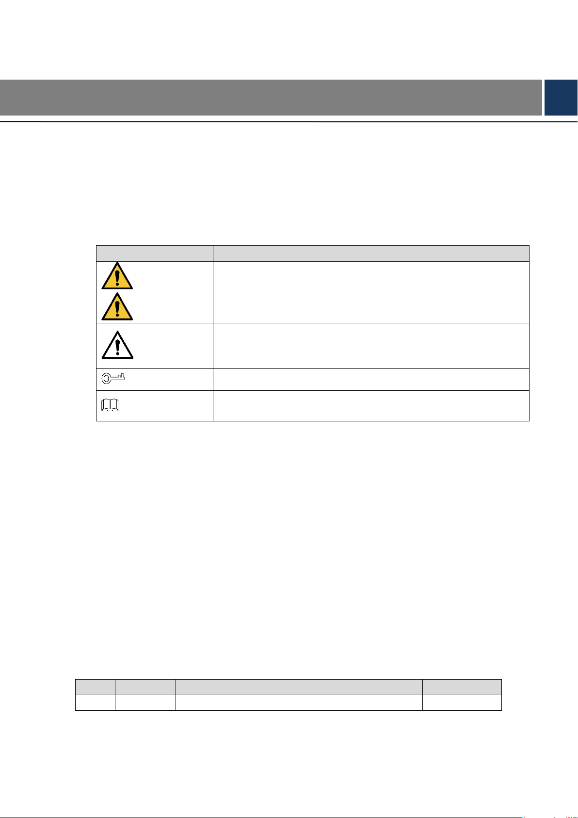
Signal Words
Meaning
DANGER
Indicates a high potential hazard which, if not avoided, will result in
death or serious injury.
WARNING
Indicates a medium or low potential hazard which, if not avoided,
could result in slight or moderate injury.
CAUTION
Indicates a potential risk which, if not avoided, could result in
property damage, data loss, lower performance, or unpredictable
result.
TIPS
Provides methods to help you solve a problem or save you time.
NOTE
Provides additional information as the emphasis and supplement to
the text.
No.
Version
Revision Content
Release date
1
V1.0.0
First release
January 2019
Models
MXVR 4104 Series
Safety Instructions
The following categorized signal words with defined meaning might appear in the Guide.
Foreword
Terms
To simplify descriptions, frequently cited functions and names in this manual have the following
meanings:
Unless otherwise specified, “Device” in this document refers to “MXVR4104 series
products”.
“Remote devices” in this manual refer to NVR, IPC, speed domes connected with the
devices through network.
“Smart module” in this manual means smart cards installed on devices.
“IP host” in this manual refers to hosts configured with IP addresses. PC, NVR, IPC, and
speed domes are all IP hosts.
To keep the devices safe, IP addresses, MAC addresses, and serial numbers cited in this
manual have all been modified.
Revision History
Foreword IV
Page 6

The following section describes how to use this product correctly and how to prevent dangers
and property loss in using it. Before using this product, read this Manual carefully and comply
with it strictly. Keep this Manual properly after reading.
Requirements
Do not place or install the device near a heat source or where there is direct sunshine.
Do not install the device in a humid, dusty, or smoggy place.
Install the device horizontally or in a stable place. Take measures to prevent it from falling.
Do not drip or splash liquid onto the device. Make sure that the device does not bear any
Prevent foreign objects from entering the Device, which might result in damage.
Install the device in a place with good ventilation. Do not clog the air vents of the device.
Use the device only within the rated input and output range.
Do not dismantle the device without permission.
Do not transport the Device with the front panel on the bottom.
Transport, use and store the Device under the allowed humidity and temperature
Do not expose the Device to water or excessive moisture when washing the car. A failure
The dust on the circuit board will cause short circuit, which affect the normal operation of
Keep the Device installed horizontally and make sure the internal anti-vibration
Unlock the HDD box before pulling it out; otherwise there might cause damage to the
After all the cables are connected, tie up the cables to avoid the dangers such as short
When a device is connected with a car mount display, mount the camera at least 2m away
Important Safeguards and Warnings
objects filled with liquid to prevent liquid from flowing into the device.
conditions.
to follow this instruction might result in short circuit, fire, or other malfunctions.
the Device and even damage the Device.To make the Device work stably for a long time,
please regularly use the brush to remove the dust from components, including circuit board,
connectors, and chassis.
components work properly.
Device.
circuit, heat and electric shock resulted from loose cables.
from the display. If the camera and display are too close, tune down the volume of the car
mount display to avoid squeal.
Power Requirements
Use the battery exactly as prescribed; otherwise, the battery might catch fire or explode!
Always replace with the same type of batteries!
Use the wires (power cords) recommended for the region where the device is used within
the specified range of specifications!
The appliance coupler is a disconnection device. Keep a convenient angle when using it.
Important Safeguards and Warnings V
Page 7

Take care to complete the circuit connection. A failure to follow this instruction might result
in Device damage.
Prevent short circuit from occurring on all external wiring parts.
After all the lines connections are completed, you can start connecting power cable.
Ensure the project is well grounded to avoid interference to video and audio signals and
avoid electrostatic or induced voltage to damage the Device.
Unplug the power cable before you remove the audio/video signal cable, RS-232 or
RS-485 cable; otherwise these ports might be damaged.
Important Safeguards and Warnings VI
Page 8

Regulatory Information ............................................................................................................................. I
Cybersecurity Recommendations .......................................................................................................... II
Foreword .................................................................................................................................................. IV
Important Safeguards and Warnings ..................................................................................................... V
1 Product Introduction ............................................................................................................................. 1
Product Overview .......................................................................................................................... 1 1.1
Functions ....................................................................................................................................... 1 1.2
2 Dimension and Installation .................................................................................................................. 3
Out-of-box Audit ............................................................................................................................ 3 2.1
Device Structure............................................................................................................................ 3 2.2
2.2.1 Front Panel ......................................................................................................................... 3
2.2.2 Rear Panel .......................................................................................................................... 4
2.2.3 Interface definitions............................................................................................................. 6
2.2.4 Dimensional drawing .......................................................................................................... 9
Installation ................................................................................................................................... 10 2.3
2.3.1 Installing HDD ................................................................................................................... 10
2.3.2 Installing SIM Card and SD Card ..................................................................................... 13
2.3.3 Installing antenna .............................................................................................................. 13
2.3.4 Fixing the Device .............................................................................................................. 16
2.3.5 Connecting to Power Cables ............................................................................................ 16
Audio and Video Output Connection ........................................................................................... 19 2.4
Alarm Input and Output Connection............................................................................................ 19 2.5
2.5.1 Alarm Input Type ............................................................................................................... 20
2.5.2 Alarm Input Port ................................................................................................................ 21
3 Basic Settings ............................................................................................................ 错误!未定义书签。
Boot up the Device ............................................................................................ 错误!未定义书签。 3.1
Initializing Device .............................................................................................. 错误!未定义书签。 3.2
Log into the Device ........................................................................................... 错误!未定义书签。 3.3
3.3.1 Operate on the WEB Interface ............................................................... 错误!未定义书签。
3.3.2 Operate through the Local interface ....................................................... 错误!未定义书签。
Configure IP Address ........................................................................................ 错误!未定义书签。 3.4
Configuring General Settings ............................................................................ 错误!未定义书签。 3.5
3.5.1 Setting General Information .................................................................... 错误!未定义书签。
3.5.2 Date and Time Settings .......................................................................... 错误!未定义书签。
Configuring Remote Devices ............................................................................ 错误!未定义书签。 3.6
3.6.1 Initializing the Remote Device ................................................................ 错误!未定义书签。
3.6.2 Adding a Remote Device ........................................................................ 错误!未定义书签。
3.6.3 Modify IP Address of Remote Device ..................................................... 错误!未定义书签。
Configuring Channel Type ................................................................................ 错误!未定义书签。 3.7
Configuring Record Settings ............................................................................. 错误!未定义书签。 3.8
Set up the storage plan ..................................................................................... 错误!未定义书签。 3.9
Table of Contents
Table of Contents VII
Page 9

3.9.1 Configuring Recording Schedule ............................................................ 错误!未定义书签。
3.9.2 Configure snapshot schedule ................................................................. 错误!未定义书签。
4 Function Modules Operations ................................................................................. 错误!未定义书签。
Live View ........................................................................................................... 错误!未定义书签。 4.1
4.1.1 Real-time Monitoring Channels .............................................................. 错误!未定义书签。
4.1.2 Voice intercom ........................................................................................ 错误!未定义书签。
4.1.3 PTZ Console ........................................................................................... 错误!未定义书签。
4.1.4 Image and Alarm out Settings ................................................................ 错误!未定义书签。
Video playback .................................................................................................. 错误!未定义书签。 4.2
4.2.1 Control .................................................................................................... 错误!未定义书签。
4.2.2 Playing Back Recorded Video Files ....................................................... 错误!未定义书签。
4.2.3 Clipping Recorded File ........................................................................... 错误!未定义书签。
4.2.4 Downloading Recorded Files.................................................................. 错误!未定义书签。
Configuring Alarm Events Settings ................................................................... 错误!未定义书签。 4.3
4.3.1 Alarm types ............................................................................................. 错误!未定义书签。
4.3.2 Alarm Event Settings .............................................................................. 错误!未定义书签。
5 Configuring System Settings ................................................................................... 错误!未定义书签。
Configuring lens parameter .............................................................................. 错误!未定义书签。 5.1
5.1.1 Configuring Image Properties ................................................................. 错误!未定义书签。
5.1.2 Configuring Encode Parameters ............................................................ 错误!未定义书签。
5.1.3 Configuring Channel Name .................................................................... 错误!未定义书签。
5.1.4 Configuring Face Detection .................................................................... 错误!未定义书签。
5.1.5 View Channel Info ................................................................................... 错误!未定义书签。
Network Parameters Configuration................................................................... 错误!未定义书签。 5.2
5.2.1 Connection Setting ................................................................................. 错误!未定义书签。
5.2.2 Configuring 3G/4G Network Settings ..................................................... 错误!未定义书签。
5.2.3 Configuring 3G/4G Settings .................................................................... 错误!未定义书签。
5.2.4 Configuring Email Settings ..................................................................... 错误!未定义书签。
5.2.5 Configuring FTP Settings ....................................................................... 错误!未定义书签。
5.2.6 Setting up auto registration ..................................................................... 错误!未定义书签。
5.2.7 Configuring P2P Settings ....................................................................... 错误!未定义书签。
5.2.8 Configuring Switch Settings .................................................................... 错误!未定义书签。
5.2.9 Configuring Network Testing Settings .................................................... 错误!未定义书签。
Configuring Alarm Events ................................................................................. 错误!未定义书签。 5.3
5.3.1 Configuring Video Detection Settings ..................................................... 错误!未定义书签。
5.3.2 Configuring Alarm Input Settings ............................................................ 错误!未定义书签。
5.3.3 Abnormality ............................................................................................. 错误!未定义书签。
5.3.4 Configuring Alarm Output Settings ......................................................... 错误!未定义书签。
5.3.5 View alarm information ........................................................................... 错误!未定义书签。
Configuring display output ................................................................................ 错误!未定义书签。 5.4
5.4.1 Configuring resolution ............................................................................. 错误!未定义书签。
5.4.2 Configuring tour parameters ................................................................... 错误!未定义书签。
5.4.3 Adjust TV parameters ............................................................................. 错误!未定义书签。
5.4.4 Configuring Video Mirror settings ........................................................... 错误!未定义书签。
Managing Storage Device................................................................................. 错误!未定义书签。 5.5
5.5.1 Configure basic information .................................................................... 错误!未定义书签。
5.5.2 HDD management .................................................................................. 错误!未定义书签。
Table of Contents VIII
Page 10

5.5.3 Viewing HDD Information ....................................................................... 错误!未定义书签。
Configuring System Information ....................................................................... 错误!未定义书签。 5.6
5.6.1 Configuring Zero-Channel Settings ........................................................ 错误!未定义书签。
5.6.2 Configuring RS-232 Port Parameters ..................................................... 错误!未定义书签。
5.6.3 Managing User Account ......................................................................... 错误!未定义书签。
Safety ................................................................................................................ 错误!未定义书签。 5.7
5.7.1 Set up system services ........................................................................... 错误!未定义书签。
5.7.2 HTTPS Settings ...................................................................................... 错误!未定义书签。
Configuring Vehicle Settings ............................................................................. 错误!未定义书签。 5.8
5.8.1 Configuring Speed .................................................................................. 错误!未定义书签。
5.8.2 Position Correction ................................................................................. 错误!未定义书签。
5.8.3 Configuring Position Report .................................................................... 错误!未定义书签。
6 Auto Maintenance ...................................................................................................... 错误!未定义书签。
Requirement for Maintenance .......................................................................... 错误!未定义书签。 6.1
System Information ........................................................................................... 错误!未定义书签。 6.2
6.2.1 Review running status ............................................................................ 错误!未定义书签。
6.2.2 Version .................................................................................................... 错误!未定义书签。
6.2.3 Viewing System Logs ............................................................................. 错误!未定义书签。
6.2.4 Viewing Satellite Information .................................................................. 错误!未定义书签。
6.2.5 Viewing Data Rate Information ............................................................... 错误!未定义书签。
6.2.6 Alarm ....................................................................................................... 错误!未定义书签。
Auto Maintain .................................................................................................... 错误!未定义书签。 6.3
6.3.1 Reboot system ........................................................................................ 错误!未定义书签。
6.3.2 Configuring auto deleting old files .......................................................... 错误!未定义书签。
6.3.3 Configuring auto boot up ........................................................................ 错误!未定义书签。
6.3.4 Configuring auto shutdown system ........................................................ 错误!未定义书签。
6.3.5 Auto Delay for Shutdown ........................................................................ 错误!未定义书签。
Backing Up and Restoring ................................................................................ 错误!未定义书签。 6.4
6.4.1 Backing up Configurations ...................................................................... 错误!未定义书签。
6.4.2 Restoring Configurations ........................................................................ 错误!未定义书签。
6.4.3 Restoring to Default ................................................................................ 错误!未定义书签。
Upgrading System Firmware ............................................................................ 错误!未定义书签。 6.5
Network sniffer .................................................................................................. 错误!未定义书签。 6.6
7 Operating by DSS .............................................................................................................................. 211
8 FAQ ..................................................................................................................................................... 212
Mouse Operations ........................................................................................................... 216 Appendix 1
HDD Capacity Calculation .............................................................................................. 218 Appendix 2
Technical parameters ...................................................................................................... 219 Appendix 3
Table of Contents IX
Page 11

Function
Description
Storage
Stores the data in the dedicated format which cannot be falsified and
ensure the data security.
Compression
Supports multi-channel audio and video signals, and each channel
signal supports real-time compression by independent hardware to
realize the sync between sound and image.
Backup
Plug in a USB storage device (such as USB flash disk and mobile
HDD) to back up
You can back up the data by downloading the files from the device
HDD and SD card through Internet
Video playback
Every channel supports real-time and independent recording, and
you can play backward, monitor on Internet, query and download
recordings
Supports several playback modes: Slow playback, fast playback,
backward playback, and frame-by-frame playback.
Displays the accurate time when the event occurred during
playback.
Operation through
Network
Supports remote operations through network, such as real-time remote
monitoring, recorded video search and playback, and PTZ control
1 Product Introduction
Product Overview 1.1
Based on the new generation platform, the MXVR4104 series products are onboard video
monitoring products that integrate video capturing, locating, and drive recording.
Features:
Up to 4-channel coaxial video input and 4-channel remote video input.
Compatible with AHD, TVI, and CVBS video signals.
The use of H.264/H.265 encoding ensures high encoding efficiency and saves storage
space.
Netcom wireless network modules (3G, 4G and Wi-Fi modules are optional) are built in
after full consideration of network application needs of car mount products.
The use of professional car-mount design in standard size features low power
consumption and novel shape.
Wide power voltage range adapts to various car mount power supply.
Unique HDD and SD car storage design makes recording backup and management easier.
This product can be widely used for car mount monitoring in public transportation, long-range
passenger transport, police patrol, urban management patrol, cash carriers, hazardous goods
transport, and logistics transport, or video monitoring in harsh environments.
Functions 1.2
Product Introduction 1
Page 12

Function
Description
Alarm linkage
Provides eight routes of electric level alarm inputs that can connect
to signals such as car door signal, cornering lamp signal, reversing
and braking signal, to give an indication and take a record
Supports 2 routes of electric level alarm output to realize easy
alarm linkage
Supports protective circuit for alarm input port and alarm output
port, which protect the Device from damage.
Communication
interfaces
Offers RS-485 interfaces to connect with external devices
Offers RS-232 interfaces to connect with external car mount
display
Offers standard Ethernet ports that support remote network
accessing
Smart operations
Mouse operations
The same settings in the menu can be quickly copied and pasted
Satellite
positioning
Supports positioning function and recording linkage. Recording search
can be linked with vehicle moving track
3G/4G, Wi-Fi
networks
Adopts the latest wireless communication technology, which has
improved the manageability of the Device.
Removable HDD
The extractable and seismic design make you lock and move the HDD
easily to realize data backup. Just connect the removable HDD to the
USB port of PC, you can perform data-related operations conveniently.
Dual stream
To cope with the low-bandwidth and instability of wireless network, the
Device adopts the dual stream technology (respectively encode the
real-time video and encode video in network transmission) to optimize
the coding of network transmission, which improves the control
capability of wireless network transmission
Rollover and
collision detection
The integrated G-sensor supports rollover and collision detection and
timely releases alarms through the platform
Product Introduction 2
Page 13
No.
Name
Descriptions of interfaces and indicators
1
RJ-45 network port
One network port to connect the Recorder to network.
USB interface
Two USB ports that connect to peripheral devices such as
USB storage device and mouse.
Describes the installation of hardware. Prior to installation, you need to know about the front
panel, rear panel, structural sizes, and interface definition of the device. Then you can install
corresponding HDD, SIM card, SD card, antenna, and devices.
2 Dimension and Installation
Out-of-box Audit 2.1
When you receive the Device, unpack the box for checks.
Firstly, check if there is any damage on the Device appearance (although the packing materials
are specially selected for protecting the Device from most of accidental hit during
transportation). Secondly, open the accessory box to check if the accessories are complete
against the packing list.
Instructions about front panel, rear panel, and labels:
The functions of indicator lights and ports are described in the later chapter of the Manual.
The labels on the Device are very important for our after-sales service. To ensure the
after-sales service, keep the labels well, and do not tear or throw away. You need to
provide the serial number of the product when calling the after-sales service.
Device Structure 2.2
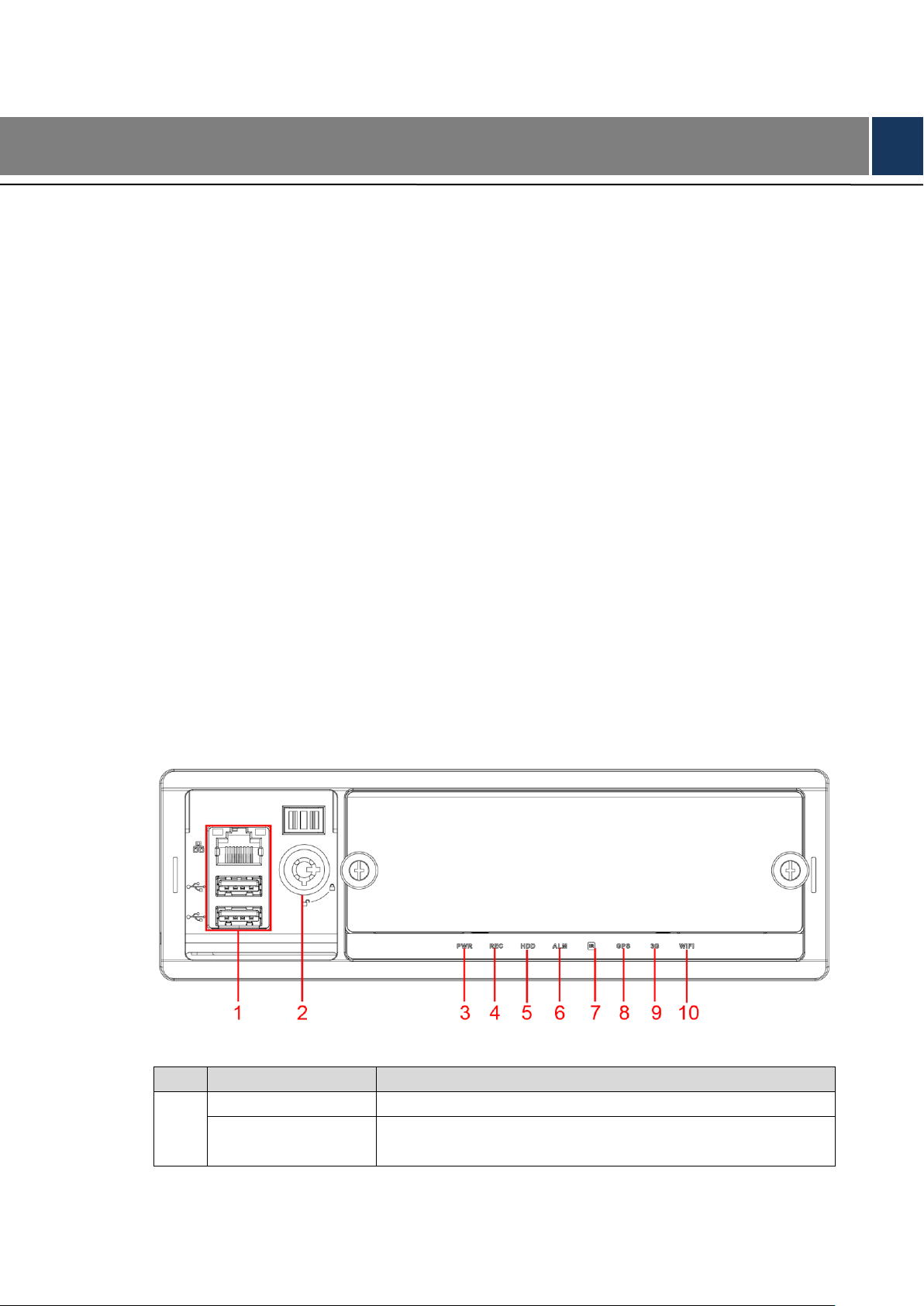
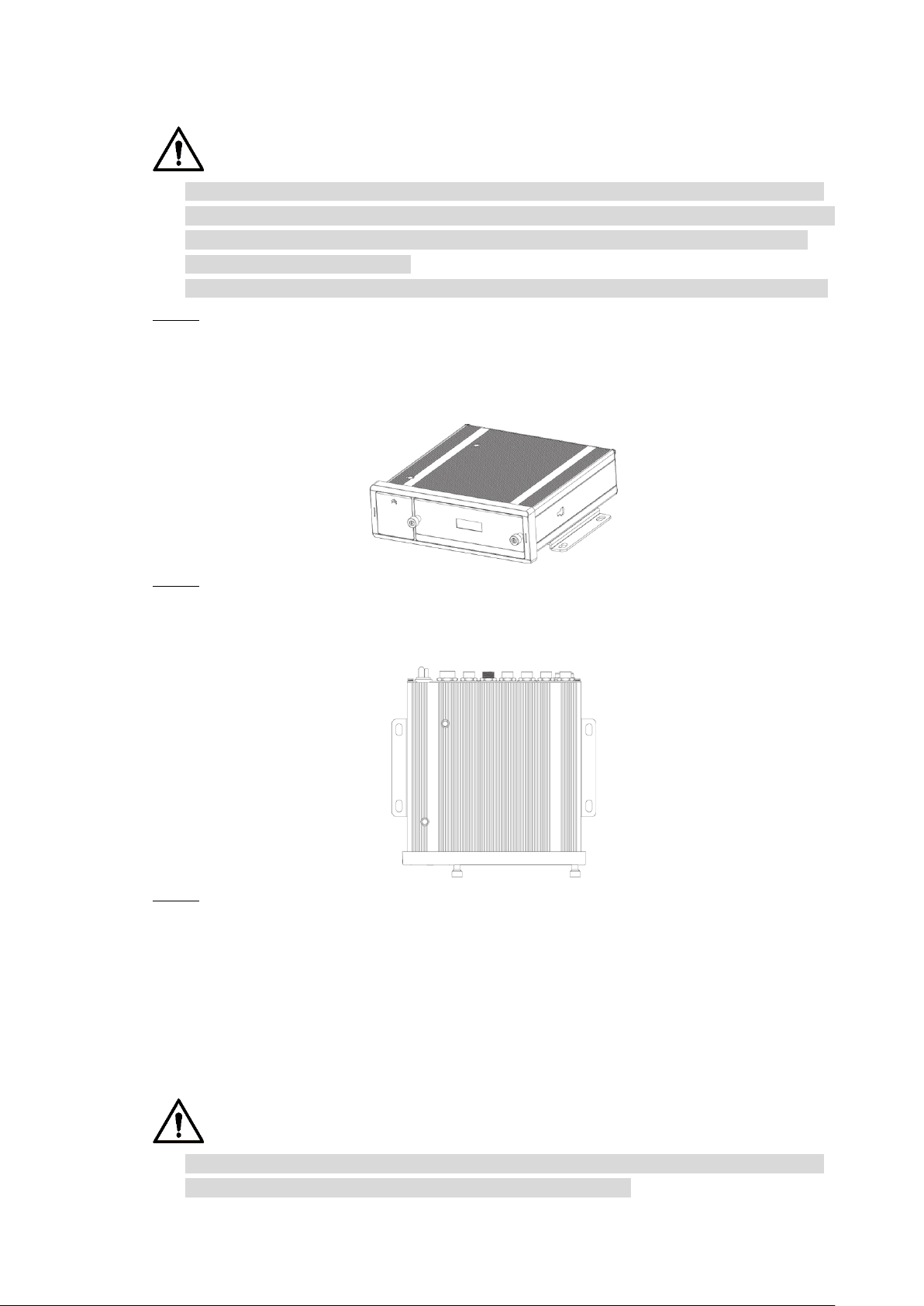
2.2.1 Front Panel
Describes the functions of the indicators and interfaces of the front panel.
Front Panel Figure 2-1
Table 2-1 Descriptions of interfaces and indicators
Dimension and Installation 3
Page 14

No.
Name
Descriptions of interfaces and indicators
2
Lock switch (Device
switch)
When pulling out HDD, the Device must be unlocked,
and if the Device is turned on, it will shut down
automatically.
To protect the HDD, this Device cannot be turned on if it
is unlocked. Turning on the device only after locking it
3
PWR
The red light is always on when the Device is powered on,
and off when the Device is powered off
4
REC
Recording status indicator. The blue light is always on when
recording, and off when not
5
HDD
HDD status indicator. The light off indicates the hard disk runs
normal while the light keeping red indicates that there are
something wrong with the hard disk (such as disk missing,
loose disk connection and nearly full space occupation).
6
ALM
Alarm status indicator. The red light is always on when alarms
occur, and off when not
7
IR
Receives infrared signal from remote control.
8
GPS
GPS status indicator. Glows blue when GPS positioning is
working properly, and the indicator is off when GPS function is
not enabled.
NOTE
This function is supported on the Device with GPS positioning
module.
9
3G
3G status indicator. Glows blue when 3G dial-up is working
properly, and the indicator is off when 3G function is not
enabled.
NOTE
This function is supported on the Device with 3G module.
10
Wi-Fi
Wi-Fi status indicator. Glows blue when Wi-Fi connection is
correct, and the indicator is off when Wi-Fi is disconnected.
NOTE
This function is supported on the Device with Wi-Fi module.
2.2.2 Rear Panel
Describes the interface functions of the rear panel.
Figure 2-2 shows the rear panel of the Device. Refer to Table 2-2 for interface function
description, and “2.2.3Interface definitions” for interface definitions.
Dimension and Installation 4
Page 15
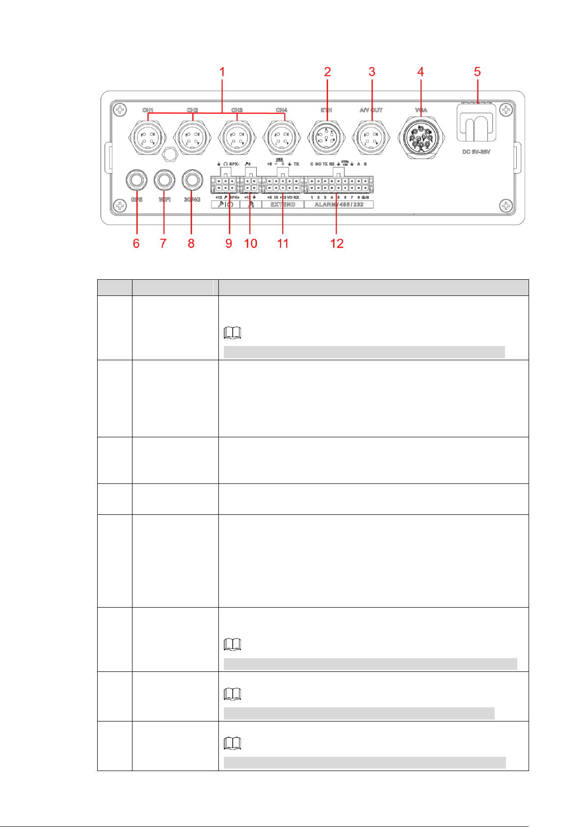
Rear panel Figure 2-2
No.
Name
Function
1
CH1-4
Connects to HDCVI or analog mobile camera, such as CVBS,
TVI, and AHD. Refer to "2.2.3.1 CH1-4 Port" for details.
NOTE
Different devices corresponds to different number of channels
2
ETH interface
The aviation port can be converted to an RJ45 interface through a
adapter cable.
Access to PoE power switch to realize IPC remote access.
Connects to the network to realize the login and Web
interface operation of the Device.
3
AV OUT port
Connects to the display with audio function on the vehicle for
simultaneously video and audio data output. For details, see “2.4
Audio and Video Output Connection.”
4
VGA port
Outputs analog video data to the connected display with VGA
port. For details, see "2.2.3.3 VGA Port."
5
Power cable
Connects to 6V DC–36V DC power for power supply from vehicle
battery. See "2.2.3.2 Power Input" for details.
The red end with fuse is the anode of the power supply
(always-live wire)
The black wire is the ground wire
The orange one is the ACC signal (key starting wire)
6
Positioning
antenna port
Connects with positioning antenna for receiving satellite
positioning signals
NOTE
This function is supported on the Device with positioning module
7
Wi-Fi antenna
port
Connects to Wi-Fi antenna and receives Wi-Fi signals.
NOTE
This function is supported on the Device with Wi-Fi module.
8
3G/4G antenna
port
Connects to 3G/4G antenna for receiving 3G/4G signals.
NOTE
This function is supported on the Device with 3G/4G modules.
Table 2-2 Descriptions of rear panel interfaces
Dimension and Installation 5
Page 16
No.
Name
Function
9
Voice talk port
Connects to voice talk device. For details, see “Voice Talk Port”
introduction.
10
External pickup
port
Connects to external pickup. For details, see “External pickup
port” introduction.
11
EXTEND port
See “EXTEND Port” introduction.
12
ALARM/485/232
Alarm input/output port: Includes alarm input/output port,
grounding, and 12V output port. For details, see “2.5Alarm
Input and Output Connection.”
TX,RX: RS-232 port sender and receiver that connect to
RS-232 port.
A, B: Controls PTZ operations.
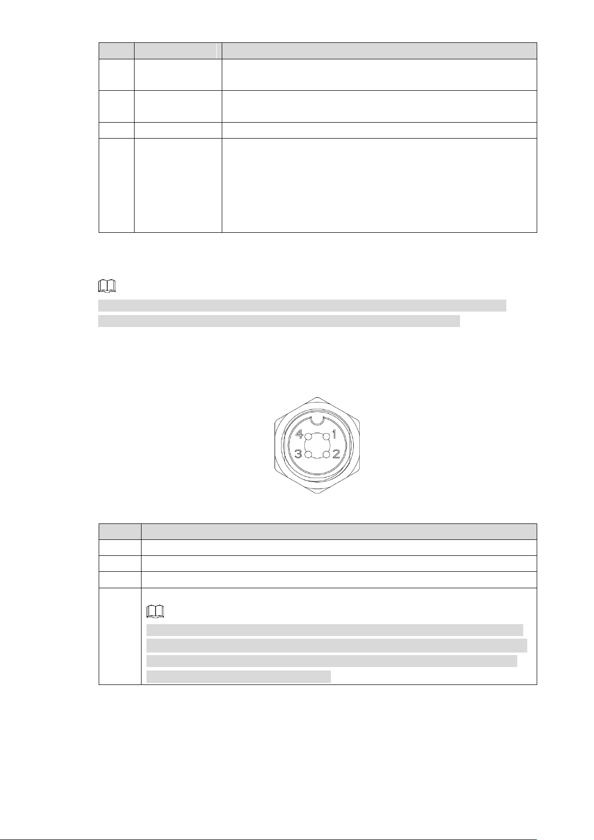
2.2.3 Interface definitions
No.
Description
1
12V power supply to camera.
2
Grounding port.
3
Grounding port.
4
Video input port to receive video signal from camera.
When your camera is the kind which outputs AHD, TVI or CVBS video signal, the
Recorder can only receive the video signal and cannot receive the audio signal;
when your camera is the kind which outputs CVI video signal, the Recorder can
receive both the video and audio signal.
NOTE
This Manual only describes functions of all jacks of each interface. You can follow these
descriptions to prepare cables or contact our sales staff for purchasing cables.
2.2.3.1 CH1-4 Port
CH1-4 port Figure 2-3
Table 2-3 Port description
Dimension and Installation 6
Page 17

2.2.3.2 Power Input
Cable color
Pins
Red
Anode input
Black
Ground
Orange
ACC signal input
No.
Function
No.
Function
No.
Function
1
+12V/1A output
5
Audio output
9
VGA line sync
2
Ground line
6
VGA_B
10
VGA line sync
3
VGA_G
7
VGA_R
-
-
4
RXD_232
8
TXD_232
-
-
Name
Function
+5
USB +5V (upper line)
+5
USB +5V (upper line)
2.2.3.3 VGA Port
Figure 2-4
Table 2-4 Power input interfaces (left to right)
Power input interface
VGA interface Figure 2-5
2.2.3.4 EXTEND port
EXTEND port Figure 2-6
Dimension and Installation 7
Page 18
Name
Function
-
USB data- and USB data+ that connect to USB port.
+
IR
Remote control signal indicator. Receives signals from remote control.
+12
+12V/1A output.
Ground
VO
AV video output
RX
RS-232 serial port sender and receiver that connects to RS-232 port
TX
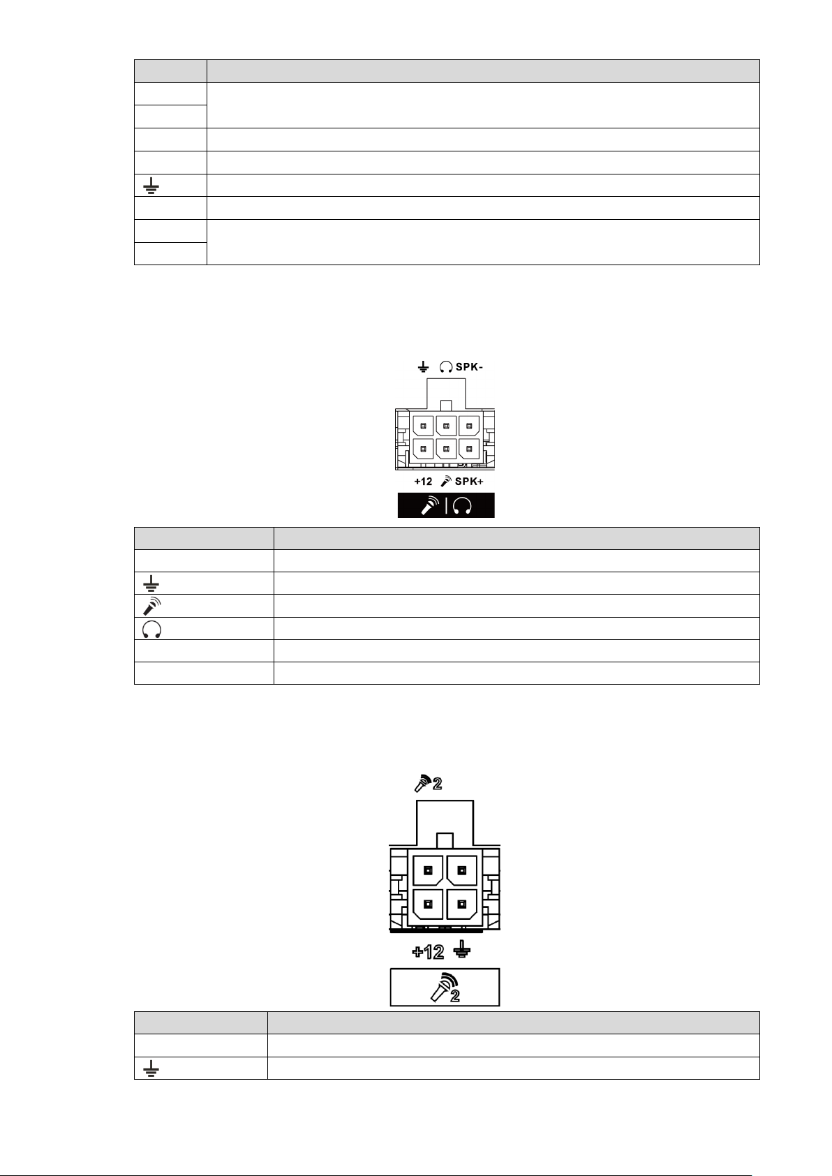
2.2.3.5 Voice talk port
Name
Function
+12
+12V output
Ground
Mic In that can connect to microphone.
Mic Out that can connect to earphone.
SPK+
Speak positive pole
SPK-
Speak negative pole
Name
Function
+12
+12V output
Ground
Voice talk port Figure 2-7
2.2.3.6 External pickup port
External pickup port Figure 2-8
Dimension and Installation 8
Page 19
Name
Function
Mic In that can connect to pickup.
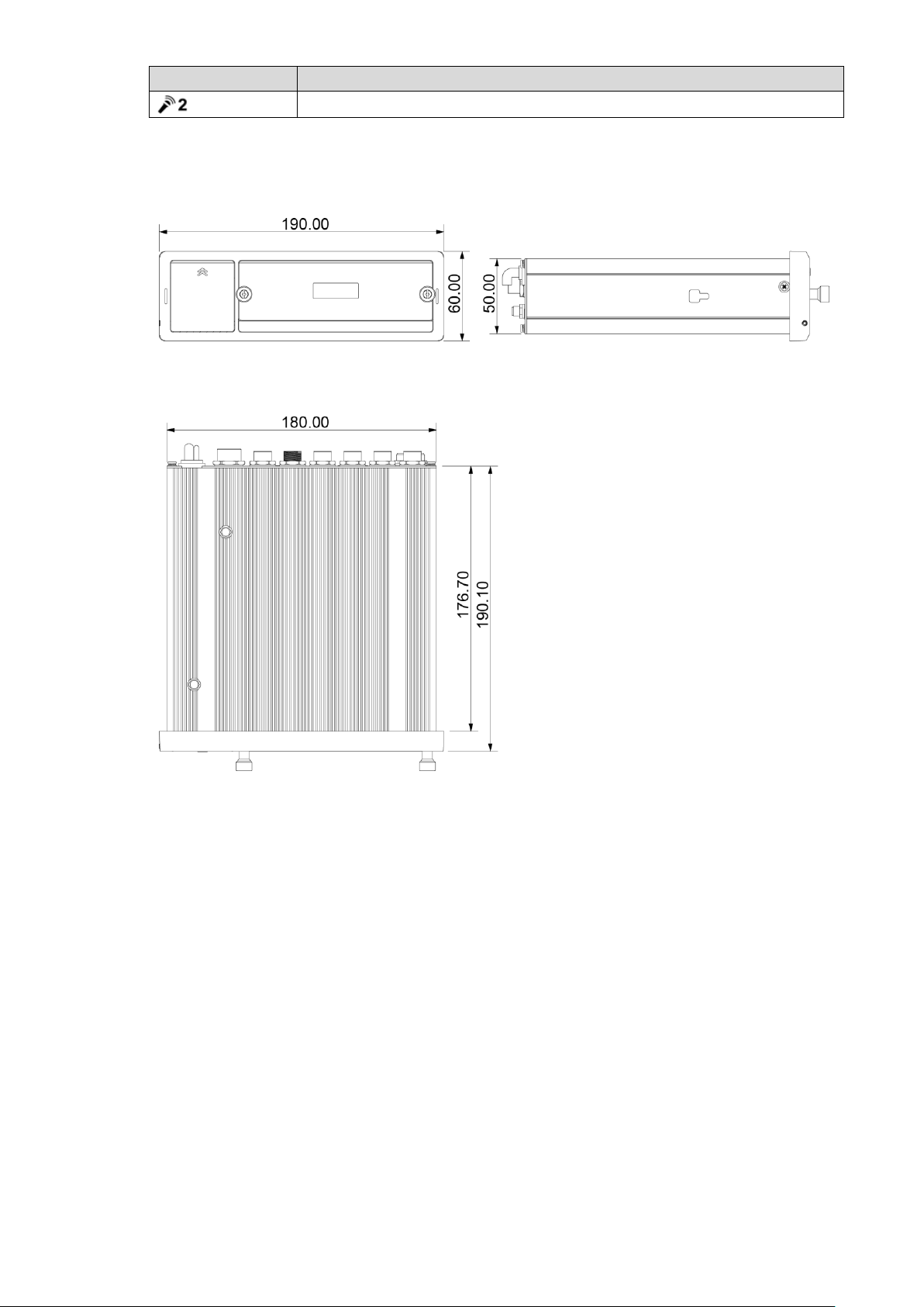
2.2.4 Dimensional drawing
Physical Dimensions (mm) Figure 2-9
Dimension and Installation 9
Page 20
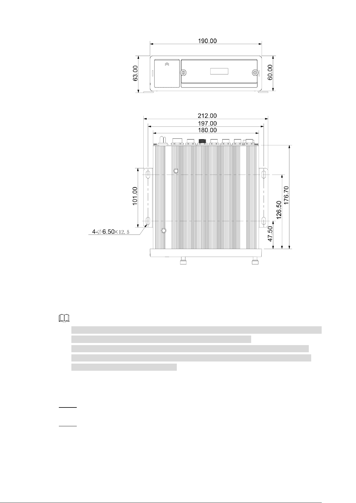
Hangers Installation Dimension Diagram (mm) Figure 2-10
Installation 2.3
When you receive the Device, unpack the box to check the Device appearance and structures,
and then install the SIM card, SD card, and HDD.
NOTE
Before the installation is complete, make sure the Device is disconnected from power, and
do not plug or unplug components when the power is connected.
When installing and taking out HDD, the Device electronic lock must be in "unlocked"
status. After the installation is complete, the Device electronic lock must be in "locked"
status before powering on the Device.
2.3.1 Installing HDD
Gently press the left front cover. Step 1
The left front cover automatically opens.
Use a particular key to unlock the door. Step 2
Dimension and Installation 10
Page 21
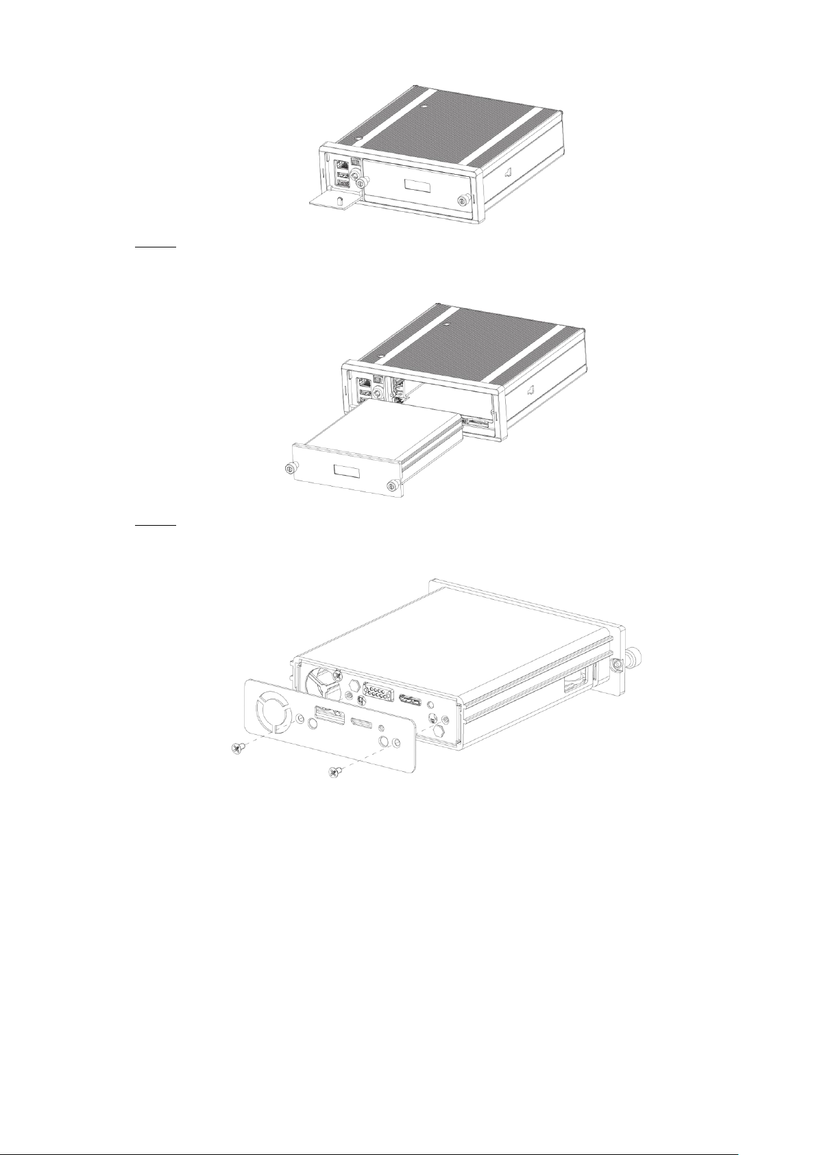
Loosen the two screws at the front panel and take out the HDD carrier along the guide Step 3
Turn on the door locker switch Figure 2-11
rail.
Take out HDD box. Figure 2-12
Loosen two screws on the back panel of the HDD carrier, take out the rear carrier panel, Step 4
and remove the HDD carrier enclosure.
Remove the HDD box: Figure 2-13
Dimension and Installation 11
Page 22
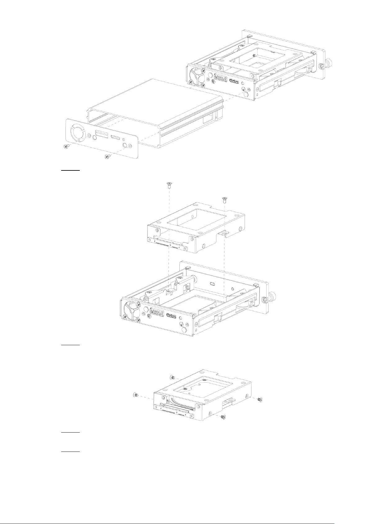
Loosen two screws of the HDD holder and remove the holder. Step 5
Use four screws to fix the HDD and HDD holder, and install the HDD holder back to the Step 6
Device.
Disassemble HDD holder Figure 2-14
Installing HDD Figure 2-15
Install the HDD carrier enclosure in place along the rails, and then fix the HDD Step 7
enclosure rear panel with two screws.
Place the HDD carrier back to the Device, tighten two screws and close the door lock. Step 8
Dimension and Installation 12
Page 23
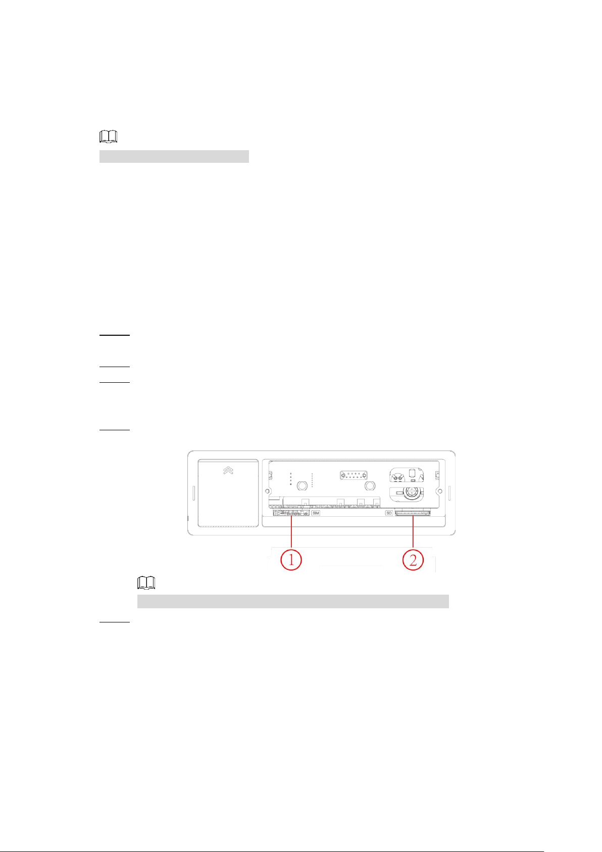
2.3.2 Installing SIM Card and SD Card
By default, the Device is delivered without the SIM card and SD card. Install them as you need.
To connect the Device to Internet through dial-up connection, you need to purchase and
install a SIM card.
NOTE
Only supports normal SIM card.
To store recording data, you need to purchase and install an SD card.
Preconditions
Make sure the power supply is disconnected. If it is not, the Device automatically shuts down
when the door lock switch is opened.
Steps
The SIM card slot and SD card slot are inside the Device.
Gently press the left front cover. Step 1
The left front cover automatically opens.
Use a particular key to unlock the door. Step 2
Loosen the two screws at the front panel and take out the HDD carrier along the guide Step 3
rail.
Positions of the SIM card slot and SD card slot are shown in Figure 2-16.
Insert the SD card and SIM card into the card slot with corresponding marks. Step 4
Installing SIM Card and SD Card Figure 2-16
In Figure 2-16, ① is the SIM card slot and ② is the SD card slot.
Put back the HDD box, tighten 2 screws and close the door locker. Step 5
2.3.3 Installing antenna
The device antenna is installed to connect the device to the network and to locate the position
of the vehicle.
Dimension and Installation 13
Page 24
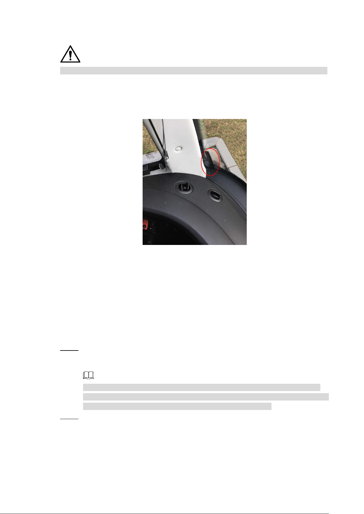
2.3.3.1 Installation of Mobile Network Antenna
CAUTION
When installing sticking antenna, make sure there is no metal material below the sticking spot.
For installation of mobile network antenna, see Figure 2-17. The flat antenna is recommended
to be vertically attached to near the wind shield (such as on the instrument panel, or under the
wind shield), or concealed inside the instrument panel.
Inside installation of Mobile Network Antenna Figure 2-17
2.3.3.2 Installation of GPS Antenna
Positioning methods include the currently mainstream GPS positioning, Beidou positioning,
with corresponding GPS antenna and Beidou antenna.
In this document, GPS antenna is used as an example to illustrate the installation steps of
locating antennas. The installation process of other locating antenna is identical.
2.3.3.2.1 Outside Installation
Place the GPS antenna on the left front of the roof. See Figure 2-18. Step 1
The antenna is magnetically attached to the roof of the vehicle. Glue can be applied to
four sides of the antenna to fix more reliably.
NOTE
To make the sensitivity and accuracy of positioning free of interference, ensure that
there is no high-power electrical or electronic interference source (such as a fan or AC
compressor) or obstacles within 1 meter around the GPS antenna.
Insert the GPS antenna lead wire into the antenna lead hole on the roof of the vehicle Step 2
and connect to the GPS antenna port inside the vehicle.
The requirements of the GPS antenna lead hole are as follows.
The inner radius is at least 10mm.
It must be waterproof.
Easy to replace and maintain the antenna.
Dimension and Installation 14
Page 25
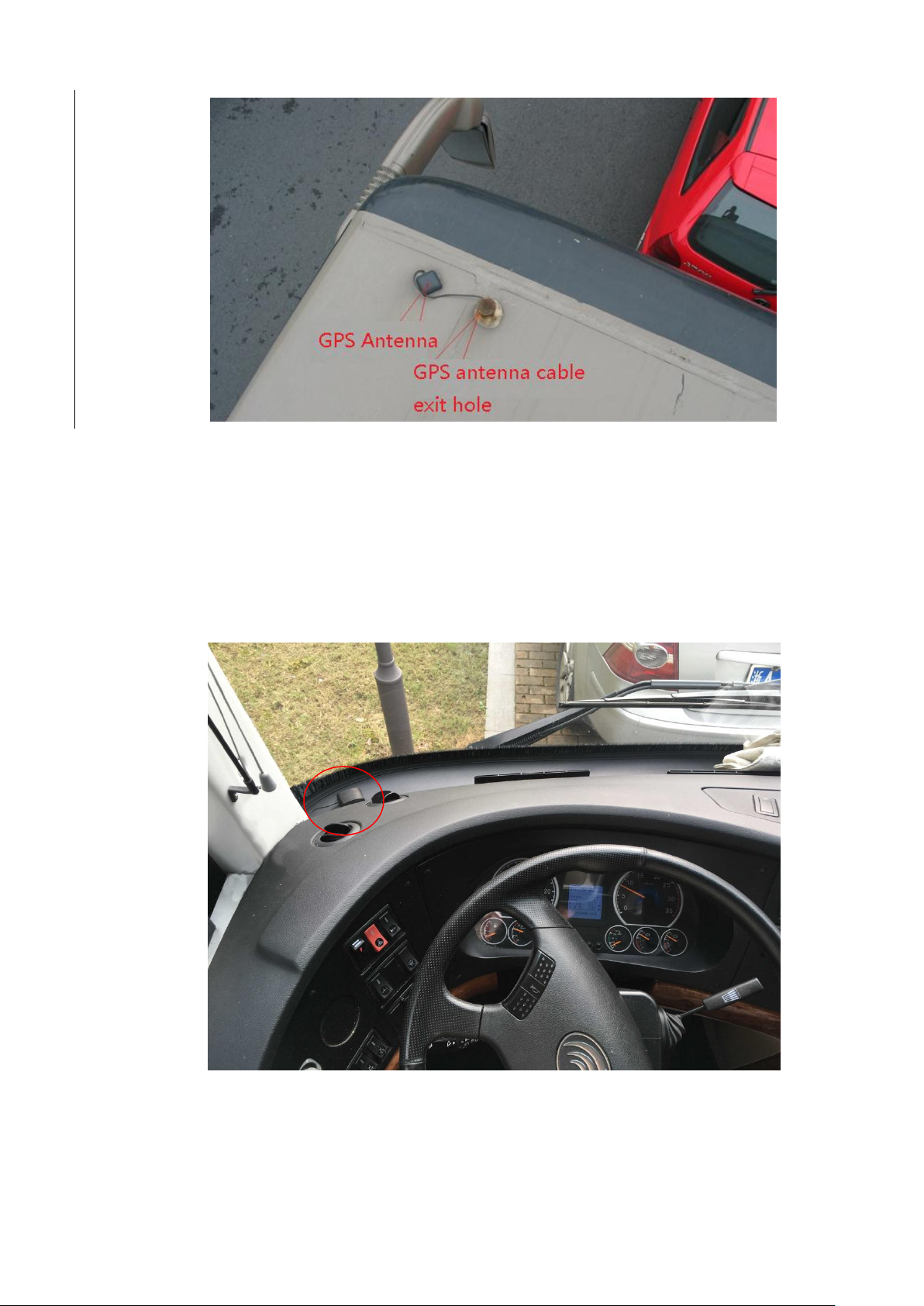
2.3.3.2.2 Inside Installation
When limited by waterproof and wiring requirements, the antenna can be installed inside the
vehicle.
Outside installation Figure 2-18
To select the installation place, it is recommended to place the antenna horizontally on the
dashboard close to the windshield, and make the GPS cable facing upward to enhance the
signal, as shown in Figure 2-19.
Inside installation Figure 2-19
Dimension and Installation 15
Page 26
2.3.4 Fixing the Device
CAUTION
Install the Device on the vehicle where it cannot be seen from outside. Avoid places with
high temperature or near the air conditioning system. High temperature shortens the life of
the Device. If going into the Device, the condensing water from the air conditioner can
short circuit or burn the Device.
Power on the Device only after all external devices are connected correctly to the Device.
Install lugs onto the Device. Step 1
1) Place washers onto the fixing screw.
2) Use fixing screws with washers, mount lugs to the bottom of the Device
respectively, and tighten the lugs.
Fix the device onto the vehicle. Step 2
1) Punch holes on the vehicle according to the installation dimensional drawing.
2) Use screws to fix the Device onto the vehicle.
Install the lugs onto the Device. Figure 2-20
Fix the Device onto the vehicle. Figure 2-21
Connect cables to the Device. Step 3
Check the voltage of the accumulator. The working voltage of this Device ranges
from 6V to 36V. To make sure the Device works stably, directly get power supply
from the accumulator.
When installing the basic wires, do not use excessive force to pull the control
wires.
2.3.5 Connecting to Power Cables
CAUTION
Before connecting the power cable, confirm whether the input voltage is between 6V DC
and 36V DC. If it is out of the range, it will damage the device.
Dimension and Installation 16
Page 27
Please make sure that the positive and negative poles of the power are connected
correctly. If not, the device may be damaged.
The diameter of the power cable should be more than 1.0 mm
recommended by our company.
When connecting the cables to the device, make sure that the main power switch of the
vehicle is turned off and the key of the vehicle is placed in the off state.
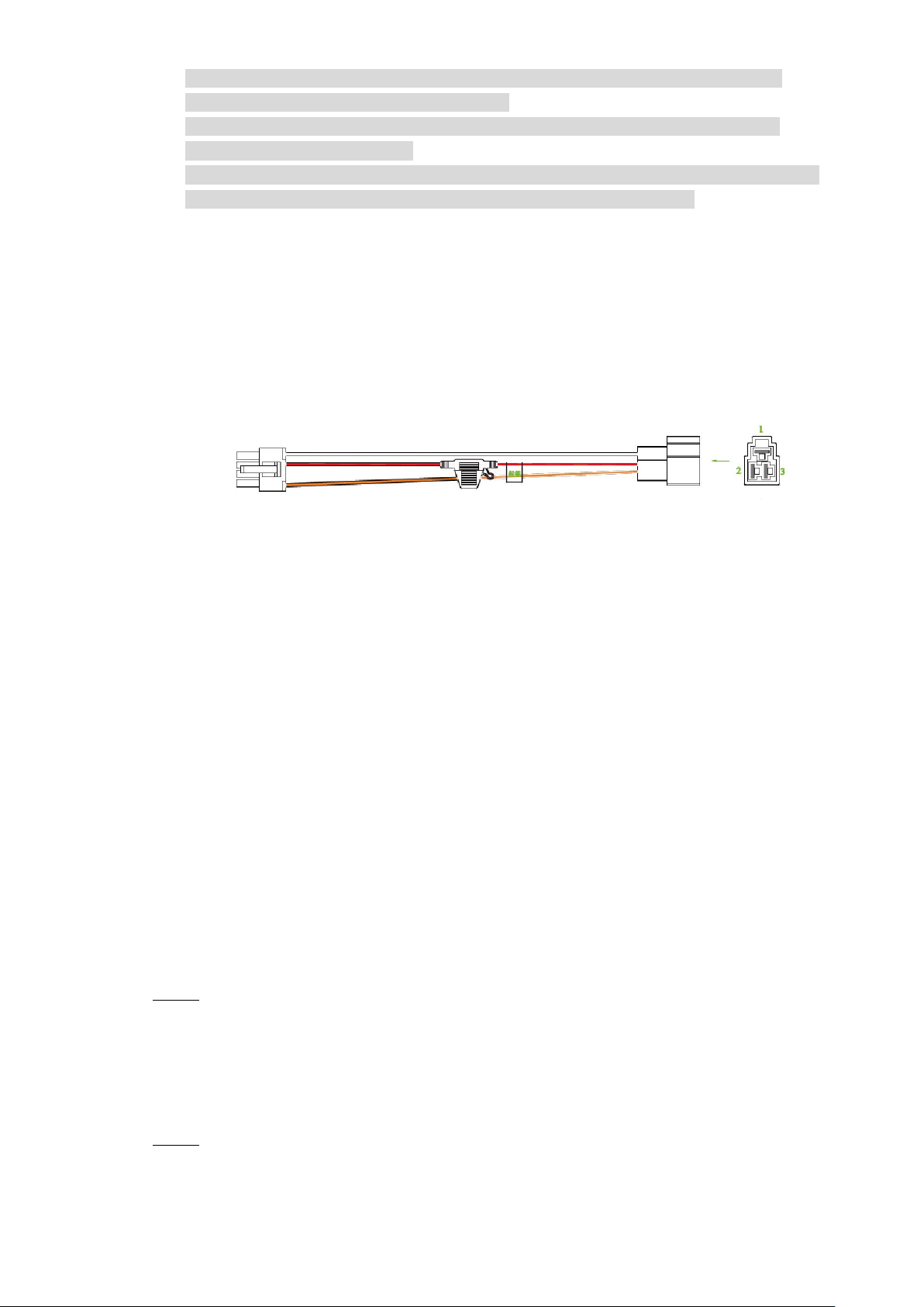
2.3.5.1 Introduction of Power Cable
For the power cable of the device, see Figure 2-22.
Directly use the power cable from the device. Connect the other end to the vehicle battery (the
right port in the figure). The red one with fuse is positive pole of the power (normal live). The
black one is the grounding cable. The orange one is the ACC signal (Key live).
2
. Use power cables
Power cable Figure 2-22
2.3.5.2 Obtain Connection Modes of the Main Power Switch
In order to ensure correct cable connection, it is necessary to obtain the connection mode of
the main power switch through three methods (is the main power switch connected to the
positive or negative pole of the battery?).
Ask the vehicle manufacture the connection modes of the main power switch of the
vehicle.
Measure with a multimeter: disconnect the main switch, then measure the voltage between
the vehicle body and the positive pole of the vehicle battery. If the voltage is 12V or 24V, it
means that the main switch disconnects the positive pole. If the voltage is 0V, then the
main switch disconnects the negative pole.
Visual inspection: whether the switch cable near the vehicle battery is connected to the
positive pole or the negative pole.
2.3.5.3 Connecting Operation
The driving recorder must be connected to the ground wire. ACC signal, and constant
electricity.
Enable the main power switch on the vehicle, place the key in the OFF state, and then Step 1
measure the normal live electricity of the vehicle.
Use a multimeter to measure the voltage on the fuse by switching to the DC voltage
range. When the multimeter detects voltage, it measures the normal live electricity on
the vehicle. Generally, the voltage is 24V DC for large vehicles and 12V DC for small
vehicles. However, this is subject to actual data.
When the vehicle key is placed at the ACC state or the ON state, the ACC signal of the Step 2
vehicle is measured.
Dimension and Installation 17
Page 28
Use a multimeter to measure the voltage on the fuse by switching to the DC voltage
range. When the multimeter detects voltage, remove the car key. If the voltage changes
to 0V, it means that the measured signal is ACC on the car.
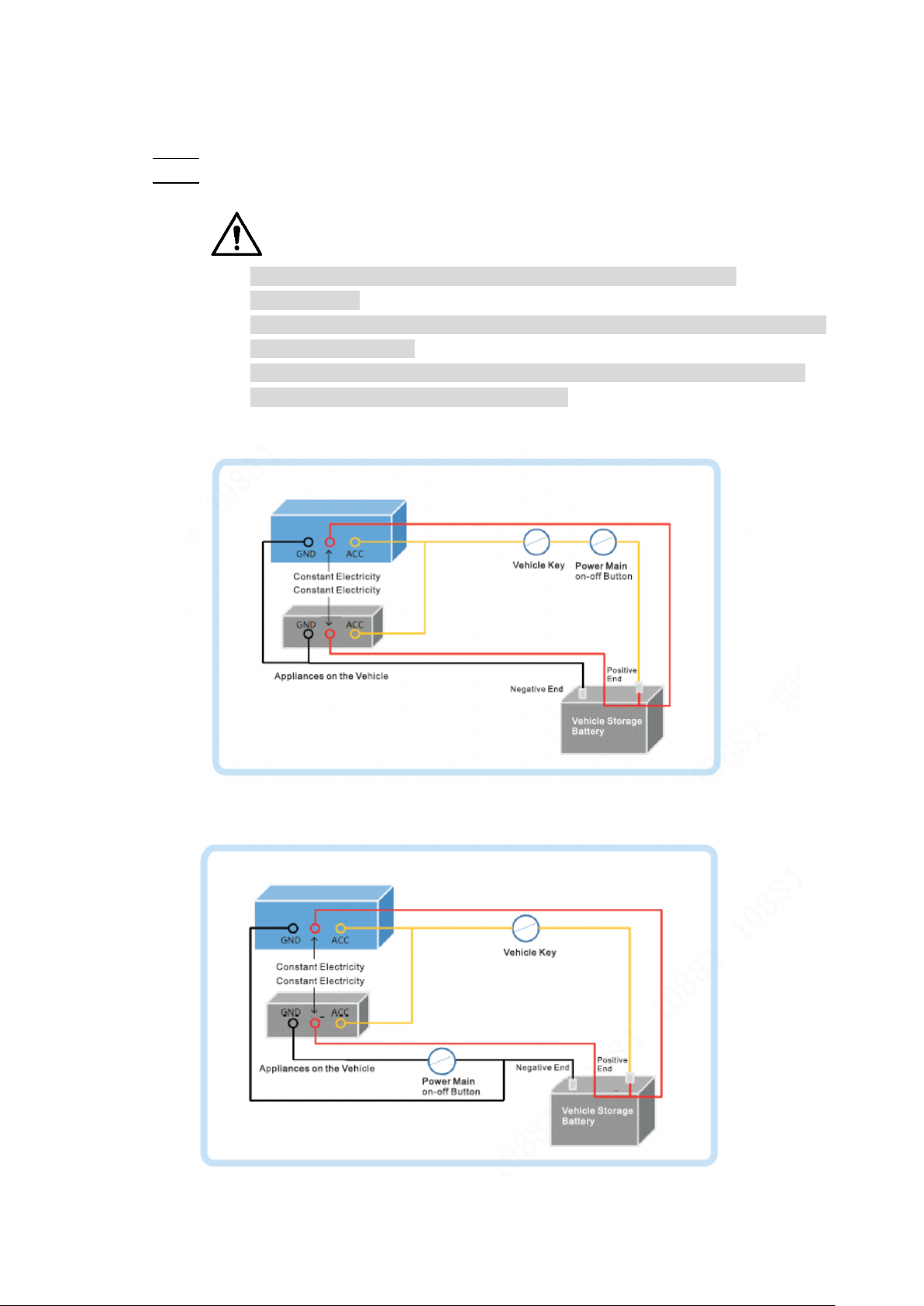
Turn off the main power switch on the vehicle, and place the key in the OFF state. Step 3
Connect the power cable according to the main power switch installation mode. See Step 4
Figure 2-23 and Figure 2-24.
CAUTION
Before connecting with power cord, select proper fuse. 7.5A fuse is
recommended.
The positive and negative poles of the battery must be equipped with protective
devices such as fuses.
For vehicles where the master power switch is installed at the cathode of the
accumulator, isolation installation is needed.
Vehicle main power switch installed on the positive pole of the vehicle battery Figure 2-23
Vehicle main switch installed on the negative pole of the vehicle battery Figure 2-24
Dimension and Installation 18
Page 29

Audio and Video Output Connection 2.4
No.
Function
1
12V external power source and no more than 1.5A.
2
Ground line
3
Audio port
4
Video port
This section helps you understand the connection of audio and video input and output when
you need to use this function.
Introduction of Video and Audio Output Port
The four-cored aviation port (Figure 2-25) can output the video and audio data.
Four-cored aviation port Figure 2-25
Video Output
The Device is provided with one CVBS (PAL/NTSC 1.0V
supports the simultaneous output from these two ports.
Read the following contents carefully before using the computer instead of monitor.
For VGA output, you need to prepare a VGA adapter cable to connect to computer.
To extend the Device life, do not keep the Device running for a long time.
Regular demagnetizing helps keep the monitor working properly.
Stay away from devices with strong electromagnetic interference.
Audio output
The audio output signal parameter is larger than 200mv 1KΩ. The audio output port can directly
connect to the display with audio function on the vehicle or active speaker, and the port can
also drive other sound output devices through amplifier.
Alarm Input and Output Connection 2.5
Before using the alarm function, learn about the connections method of alarm input and output
port.
, 75Ω) port and VGA port, and
P-P
Alarm Input
Dimension and Installation 19
Page 30

The alarm input port supports alarm signal from ground and device of 12V-24V voltage.
Name
Function
1–9
Alarm input 1~9, where 1~8 are local alarm input, 9 is a combination of
impulse and alarm (but only one function, impulse or alarm, can be
used)
If the alarm device is connected to the Device and other devices, use relay for isolation.
Alarm Output
The alarm output port cannot be connected to high-power load (less than 1A). When
constructing the output circuit, the excessive current should be prevented from causing
damage to the relay. Use the contactor for isolation when applying high-power loads.
PTZ Decoder Connection
The common-ground must be prepared for PTZ decoder and the Device; otherwise the
common-mode voltage might not be able to control the PTZ. It is recommended to use
shielded twisted pair, and the shielding layer can be used for common ground.
Prevent interference from high-voltage power, make reasonable wiring, and take measures
for lighting protection.
Parallel connect 120Ω resistance to reduce reflection and ensure high signal quality.
The Device RS-458 A line and B line cannot connect to other RS-485 output device in
parallel.
The voltage between the A line and B line must be less than 5V.
Front-end Device Grounding
The bad grounding might result in chip damage.
No restriction for types of alarm input
The alarm input can be Always On or Always Closed.
2.5.1 Alarm Input Type
Describes alarm input and output ports.
Alarm input/output port Figure 2-26
Dimension and Installation 20
Page 31

C, NO
Outputs alarm signal to alarm device.
"NO" represents normally open type.
C: Common alarm output port.
TX, RX
RS-232 serial port sender and receiver that connects to RS-232 port
Ground line
CTRL 12V
12V/0.75A output with switch control
A, B
RS-485 port that connects to speed dome with PTZ function.
2.5.2 Alarm Input Port
Both NO and NC are supported.
The GND of alarm detector is in parallel connection with COM (the power supply of alarm
detector should be from external power source). See Figure 2-27.
The GND of alarm detector is in parallel connection with GND of Device.
Connect the NC port of alarm detector to the alarm input port (ALARM).
When supplying power from external power source to the alarm device, the alarm device
should be common-grounded with the Device.
Always closed alarm input illustration Figure 2-27
Dimension and Installation 21
Page 32

3 Boot up the Device
CAUTION
Before booting up the Device, check if input voltage matches rated voltage of the Device.
Refer to international standard to offer the power input (power input that is with stable
power value and less interference ) to ensure the Device works stably and prolong its
service life.
In the first power-on, the Device needs connection to the ACC to work as intended.
Rotate the Device key to and rotate the vehicle key to ACC position. The power indicator
is on, and the Device is ready for work.
NOTE
For the first boot up or after restoring to the default factory settings, the initialization interface
is displayed on the screen. Follow on-screen instructions to initialize your Device prior to use.
Boot up the Device 22
Page 33

The Device supports access and operation through the local interface. The local interface
supports functions such as real-time preview, recording search, alarm setting, system setting,
PTZ control interface, and monitoring window.
4 Local Configurations
Initializing Device 4.1
Plug the device’s power line into a socket. Step 1
After the Device is turned on, the initialization interface is displayed. See Figure 4-1.
Device Initialization Figure 4-1
Enter the password, confirm the password and the password hint, and then click Step 2
Next.
The unlock pattern setting interface is displayed. See Figure 4-2.
NOTE
To security your account, it is recommended to keep the password properly and
change it regularly.
The password hint can help you recall the password.
Local Configurations 23
Page 34

Unlock Pattern Figure 4-2
Draw and confirm an unlock pattern. If you do not want to configure the unlock Step 3
pattern, click Skip.
The password protection interface is displayed. See Figure 4-3.
Password protection Figure 4-3
Configure the protection method for password. If you do not want to set the protection, Step 4
clear both the Reserved Phone Number check box and the Security Question check
box.
Select Reserved Phone Number and enter the phone number. The phone
number must be 11-digit number and can be normally communicated.
Select the Security Question check box, select the question and enter the
corresponding answer.
Click OK. Step 5
Local Configurations 24
Page 35

Logging into the Device 4.2
Boot up the Device. Step 6
The main interface is displayed. See Figure 4-4.
Homepage Figure 4-4
Right-click on the live view screen, the shortcut menu is displayed. Then select Main Step 7
Menu.
The SYSTEM LOGIN interface is displayed. See Figure 4-5.
Logging in System Figure 4-5
NOTE
If the unlock pattern was set during initializing, the unlock pattern login interface
is displayed. Then use the unlock pattern to login.
Click to view the password hint to help you recall the password.
If the password is lost, click and you can retrieve the password through
Local Configurations 25
Page 36

security questions or reserved phone number.
Select the admin user, and enter the corresponding password that was set during Step 8
initialization.
Click OK. Step 9
The Main Menu interface is displayed. See Figure 4-6.
Main menu Figure 4-6
Quick Configuration 4.3
After initialization, to ensure normal operation, quickly and conveniently configure basic
information, network connection, remote device adding, and recording schedule on the
Device.
4.3.1 Configure IP address
According to the network planning, configure the IP address of the Device and make sure the
Device can connect to other devices in the network.
Connect the Device to the network and make sure the Device can communicate with other
devices in the network diagram.
Preconditions
Steps
Make sure the Device is connected to the network properly.
Select Network Settings > TCP/IP under the main menu. Step 1
The system displays the TCP/IP interface, as shown in Figure 4-7.
Local Configurations 26
Page 37

TCP/IP Figure 4-7
Name
Description
IP Version
Select IPv4 or IPv6. Both versions are supported
NOTE
For IPv6 version, in the IP address box, Default Gateway box,
Preferred DNS box, and Alternate DNS box, enter 128 bits and
cannot be blank
MAC address
Host’s MAC address, cannot be modified
DHCP
When the DHCP function is enabled, the system can
automatically obtain the IP functions, while IP Address, Subnet
Mask and Gateway cannot be configured.
You can check the current IP address whether the DHCP takes
effect or not
IP address
According to your network plan, enter the modified IP address,
gateway and subnet mask
NOTE
IP address and gateway must be in the same network segment
Subnet Mask
Default gateway
Preferred DNS
IP address of the preferred DNS
Alternate DNS
IP address of the alternate DNS
Configure TCP/IP parameters. For details, see Table 4-1. Step 2
Table 4-1 TCP/IP parameter description
Click Apply. Step 3
Click Test to test network status of IP address and gateway after IP is configured.
Local Configurations 27
Page 38

4.3.2 Configuring General Settings
Name
Description
Language
Select a language for the Device system
Video standard
Displays the video encode standard
Auto Logout (minute)
Enter the time period for automatic logout if there are no
operations during this period. In this case, you need to login
again
The value ranges from 0 minutes through 60 minutes. 0
indicates there is not standby time for the Device
IPC Time Sync
The system enables IPC time by default. You can set the interval
for IPC sync with the Device based on your needs.
IPC Time Sync Cycle
License No.
Enter the license plate number of vehicle where the Device is
located
To facilitate the application of user, configure basic information of the Device as needed for
the first time.
4.3.2.1 General
Configure Language, Auto Logout Time, IPC Time Sync, License No. of the vehicle and other
information.
Select System Management > General Setup> Local Settings under the main Step 1
menu.
The General interface is displayed, see Figure 4-8.
General Figure 4-8
Configure TCP/IP parameters. For details, see Table 4-2. Step 2
Table 4-2 General settings parameters description
Click Apply. Step 3
Local Configurations 28
Page 39

4.3.2.2 Date and time settings
Name
Description
System Time
Displays the current system date and time
System Time Zone
In the Timing Mode list, if GPS or NTP is selected, configure
this parameter
Configure the Time zone that the device is at
Date format
Select a date format
Time format
Select a time format
Separator
Separator style used for date.
DST
The DST is applied in some countries or regions. Select the DST
check box if it is applied where the Device is located
1. Select the DST check box
2. According to the local regulations, configure the type, begin
time and end time for the DST
DST type
Begin time
End time
Timing Mode
Select a timing mode, including DSS, GPS, and NTP. The
default selection is NTP
DSS: The system time syncs with DSS platform
GPS: The system time syncs with satellite
NTP: The system time syncs with NTP server that you
configured
Inconsistent system time among devices in a same network might cause failure of query,
recording playback and other problems.
Select System Management > General Setup> Date&Time under the main menu. Step 1
The Date&Time interface is displayed. See Figure 4-9.
Date and time settings Figure 4-9
Configure TCP/IP parameters. For details, see Table 4-3. Step 2
Table 4-3 Date and time settings parameters description
Local Configurations 29
Page 40

Name
Description
Server
In the Timing Mode list, if NTP is selected, configure this
parameter
After configuring NTP server, the Device syncs time with NTP
server
3. In the Timing Mode list, select NTP to enable the NTP
timing function
4. Configure parameters
Server: Enter IP address of NTP server
Synchronize: Click Synchronize to sync the Device
time with NTP server
Port: The system supports TCP protocol only and the
default setting is 123
Interval: Enter the interval that you want the Device to
sync time with the NTP server. The maximum value is
65535 minutes
Synchronize
Port
Update Period (minute)
Click Apply. Step 3
4.3.3 Configuring Remote Devices
Remote devices refer to IPC, dome, and other equipment that can be connected to the
Device through network. The system supports initialization, remote device adding, etc.
4.3.3.1 Initializing the Remote Device
Initializing the remote device includes configuration of login password and IP address for the
remote device. Add and operate a remote device after initialization of the remote device.
The Device automatically initializes the IPC and the system uses the device password
and phone information by default after IPC is connected to the Device through a PoE
port.
The Device initialization might fail after IPC is connected to the Device with an upgraded
system version through a PoE port. Initialize the IPC on the Remote Device interface.
Right-click Remote Device on the main interface. Step 1
The Remote interface is displayed. See Figure 4-10.
Local Configurations 30
Page 41

Remote device Figure 4-10
Click Device Search. Step 2
The searched devices are displayed.
Enable Uninitialized function. Step 3
The uninitialized devices are displayed.
Select the check box the uninitialized device, and then click Initialize. Step 4
The Password Setting interface is displayed.
Configure the password by either of the following two ways. Step 5
Using current device password and phone info. Select the Using current device
password and phone info check box, and the remote device uses the
password and phone info of the Device.
Manually configure password for remote devices.
1) Clear the Using current device password and phone info check box.
The password setting interface is displayed.
2) In the New Password box, enter the new password and enter it again in the
Confirm Password box. Click Next.
The Password Protection interface is displayed.
3) Set up password protection.
◇ Select the Phone No. check box, and then enter the phone number. Click
Next.
◇ Click Skip if you do not want to set up password protection.
The Network interface is displayed.
Configuring network information. Step 6
Set up the network information of the remote device according to your network
plan, and click Next.
◇ Select Static, and manually set up the IP address, subnet mask, and
gateway of the remote device. If selecting multiple devices, you can set up
the IP address to increase in turn.
◇ When there is a DHCP server in the network, select DHCP, and the Device
obtains IP addresses from the DHCP server automatically.
Local Configurations 31
Page 42

Directly click Skip if you do not want to set up the network information or correct
network information already exists.
The device initialization begins. After initialization, click OK.
4.3.3.2 Adding a Remote Device
After a remote device is added, you can view video images transferred by the remote device
and modify configuration of the remote device directly on the Device. You can add a remote
device manually or by search. Different models of the Device support different number of
remote devices to be added. Add remote devices as needed.
Right-click Remote Device on the main interface. Step 1
The REMOTE interface is displayed.
Adding a remote device. Step 2
Search and Add
1. Click Device Search, the searched devices are displayed.
2. Double-click on an IP address or select the check box of a device, and then
click Add.
The device displays in the added device area.
Manual Add
1. Click Manual Add.
The Manual Add interface is displayed. See Figure 4-11.
Manual Add Figure 4-11
2. Configure TCP/IP parameters. For details, see Table 4-4.
Local Configurations 32
Page 43

NOTE
Name
Description
Channel
The channel number of the remotely connected device. You
can only select a channel that has not added remote devices
Manufacturers
Select a manufacturer according to the actual situation.
Parameters might vary by manufacture. Follow specific
parameters on the interface
IP address
Enter the IP address of remote device
TCP Port
TCP service port. The default setting is 37777. You can
configure this parameter according to your actual situation
RTSP Port
Enter RTSP Port number of remote device. The default setting
is 554
HTTP Port
Configure this parameter when the encryption function is
disabled.
Enter HTTP Port number of remote device. The default setting
is 80
HTTPS port
Configure this parameter when the encryption function is
enabled.
Enter HTTPs Port number of remote device. The default
setting is 430
Username
Enter the user name and password to login to the remote
device
Password
Remote Channel
Select the channel number that you want to connect
Encryption
This parameter must be configured when you select Onvif as
the Manufacturer.
Enable HTTPs or not. Configure HTTPs Port number when
enabled.
Decode buffer
Enter the size of decode buffer. The unit is millisecond and you
can select from 80 through 480
Service type
This must be set up when you select Onvif or Custom as the
Manufacturer
When selecting different manufacturers, the service types are
different. Select the service type based on your needs
The parameters might be different depending on the model you purchased.
Table 4-4 Manual Add Parameter Descriptions
3. Click OK.
The device displays in the added device area.
NOTE
indicates connection is successful; indicates connection
failed.
To delete the remote device, click ; to modify the information of an
added device, click or double-click the added device.
Local Configurations 33
Page 44

4.3.4 Configuring Record Settings
Name
Description
Channel
The channel that connects to the remote device is displayed.
You can select one or several channels or select All
Status
Indicates the recording status of corresponding channels. The
choices include Auto, Manual, Enable, and Stop
: Selected
: Not selected
When recording and snapshot functions are enabled, the Device can start recording and
snapshot according to the configured recording and snapshot schedule. Recording types
include automatic recording and manual recording. You can select recording type according
to different stream types.
Auto: The recording starts automatically according to the record type and recording time
as configured in the recording schedule.
Manual: Keep general recording for 24 hours for the selected channel.
Manual recording operation requires the user have the permission to access STORAGE
settings.
Right-click Manual > Record on the homepage. Step 1
The Record interface is displayed, see Figure 4-12.
Record Figure 4-12
Configure TCP/IP parameters. For details, see Table 4-5. Step 2
Table 4-5 Record control parameter description
Local Configurations 34
Page 45

Name
Description
Auto/Manual/Stop
Select the recording mode, including Manual, Auto, and Stop
Manual: Top priority. When the Manual check box is
selected, the system keeps general recording for 24 hours
for the corresponding channel
Auto: The system starts recording according to the record
type (such as general alarm, motion detect, and system
alarm) and recording time
Stop: Do not record
Enable/Disable
Enable or disable the scheduled snapshot for the corresponding
channels
Click Apply. Step 3
Name
Description
4.3.5 Set up the storage plan
Configure recording schedule and snapshot storage according to the actual application
scenarios. The Device starts corresponding types of recording and snapshot within a period
of configured time.
4.3.5.1 Configuring Recording Schedule
The default recording setting is 24 hours general recording for all channels. You can
configure conducting various recording types in any recording time.
Select Storage > Schedule > Record under the main menu. Step 1
The Record interface is displayed. See Figure 4-13.
Record Plan Figure 4-13
Configure TCP/IP parameters. For details, see Table 4-6. Step 2
Table 4-6 Record schedule parameters description
Local Configurations 35
Page 46

Name
Description
Channel
Select a channel to configure the corresponding recording schedule. To
configure the same setting for all channels, select All
Pre-record
Start recording for 0 seconds to 30 seconds before the alarm event occurs. If
you enter 0 seconds, there will be no pre-recording
Configure the recording time period. Step 3
1) Click corresponding to the week.
The Time Period interface is displayed. See Figure 4-14.
Time Period Figure 4-14
2) Select the record type and weekday, and enter the recording period.
3) Click OK.
The recording schedule appears on the Record interface to view the configured
recording schedule directly.
Click Apply. Step 4
NOTE
Click Copy to copy the settings to other channels.
4.3.5.2 Configure snapshot schedule
After snapshot schedule is configured, the Device starts corresponding types of snapshot
according to the configured snapshot schedule.
Select Storage > Schedule > Snapshot under the main menu. Step 1
The Snapshot interface is displayed. See Figure 4-15.
Local Configurations 36
Page 47

Snapshot Figure 4-15
Configuring time period for taking snapshots. Step 2
1) Click .corresponding to the week.
The Time Period interface is displayed. See Figure 4-16.
Time Period Figure 4-16
2) Select the snapshot type and weekday, and enter the period for taking snapshot.
3) Click OK.
Snapshot schedule appears on the Snapshot interface to view the configured
snapshot schedule directly.
Click OK. Step 3
Local Configurations 37
Page 48

Common Operations 4.4
4.4.1 Live View
4.4.1.1 Previewing real-time pictures
After the Device is turned on, the multi-channel preview interface is displayed. See Figure
4-17. For icon descriptions, see Table 4-7.
TIPS
See .On the live view interface, the added remote device can be dragged to other
channel if needed.
You can view the information such as time, channel name, GPS, and recording and
alarm status in the channel view.
When you move the pointer to a channel window, the live view control bar is displayed.
Click to display the channel window upside down with left and right side reversed.
The preview mode by default is general. When the face detection is enabled, right-click
Preview Mode > Face on the preview interface. The face detected is displayed at the
bottom of the preview interface.
Preview Figure 4-17
Local Configurations 38
Page 49

Table 4-7 Information Bar
Status
Description
Vehicle ACC status
Displays the ACC status of the vehicles
means ACC ON; means ACC OFF
Voltage status
Displays the accumulator voltage of the vehicle and the voltage
of the UPS carried by the Device. The voltage value on the left
is the accumulator voltage. The voltage value on the right is the
UPS voltage.
means ACC ON; means ACC OFF
Vehicle speed
Displays the vehicle speed. When the speed increases or
decreases, the icon status changes accordingly
means the vehicle is still; means it has achieved
the maximum speed
3G/4G connection status
Displays the 3G/4G connection status of the SIM card and
signal strength. The more the bars, the stronger the signals
means no SIM card or no connection with a mobile
network. means the SIM card is installed and reflects
signal strength
Wireless network status
Displays the Wi-Fi and hotspot connection status. The more the
bars, the stronger the signals
means Wi-Fi is available but not connected;
means the Wi-Fi module does not exist; indicates
Wi-Fi is connected and the strength of network signals
means the hotspot is enabled but no terminal
connections; means the hotspot is enabled and
there are terminal connections
Satellite positioning status
Displays the satellite positioning status and signal strength. The
more the bars, the stronger the signal
means satellite positioning failed; means
successful satellite positioning and signal strength.
Platform registration status
Displays the status of the Device registered to the platform
means not registered to the platform; means
registered to the DSS platform; means successful P2P
connection.
Local Configurations 39
Page 50

4.4.1.2 Shortcut menu
Shortcut Menu
Right-click on the live view screen, the shortcut menu is displayed. See Figure 4-18.
NOTE
The parameters might be different depending on the model you purchased.
Right-click menu Figure 4-18
View layout:
Main Menu: Open Main Menu interface.
Image splitting: Select View 1, View 4, View 8, and View 9 for image splitting mode.
Different model supports different view layout mode.
Search: Open the playback interface where you can search and play back record files or
pictures.
PTZ: PTZ Setting interface is displayed.
Remote Device: Search and add a remote device.
Manual: Record or Alarm Output interface is displayed.
Color Setting: Color Setting interface is displayed.
Zero-Ch Encode: Zero-Ch Encode interface is displayed.
NOTE
After entering the main menu interface, right-clicking on the screen can return to the previous
interface.
4.4.1.3 PTZ Operations
4.4.1.3.1 Controls the PTZ
Right-click on the live view screen and then select PTZ. The PTZ control panel is displayed.
See Figure 4-19.
Local Configurations 40
Page 51

PTZ support rotating device toward eight directions, up, down, left, right, left up, right up,
left down, right down.
Speed function controls the movement speed. For example, the rotation with the step
length at 8 is faster than the rotation with the step length at 1.
Click / to display or hide the PTZ functions.
4.4.1.3.2 Configuring PTZ Fn
On the preview interface, right-click PTZ > PTZ Fn on the channel of the video image Step 1
enabled in the single-window screen.
PTZ Fn interface is displayed. See Figure 4-20.
PTZ Control Figure 4-19
PTZ Fn Figure 4-20
Configure parameters
Step 2
Click Disable for Image De-Jitter to enable the image de-jitter function. When
enabled, electronic image stabilization can be realized.
Click Disable for Defog to enable the defog function. The system can
automatically remove fog in video images to clearly display images in foggy and
haze days.
Check Image NR and configure the level of noise removal. The system can
reduce the image noise according to the configured level.
Check Joystick Lock Enable to enable the joystick lock function. The joystick of
the external keyboard will be locked when enabled. Then the PTZ cannot be
operated by using the joystick.
Click Save. Step 3
Local Configurations 41
Page 52

4.4.1.3.3 Configuring PTZ Shutter
Function
Description
On the preview interface, right-click PTZ > PTZ Shutter on the channel of the video Step 1
image enabled in the single-window screen.
The PTZ Shutter interface is displayed. See Figure 4-21.
PTZ Shutter Figure 4-21
Click Disable to enable the PTZ shutter. Step 2
Click Save. Step 3
4.4.1.3.4 Configuring PTZ Functions
Click . The PTZ function interface is displayed. See Figure 4-22. SeeTable 4-8 for
functions description.
PTZ Functions Figure 4-22
Table 4-8 PTZ Function Description
Local Configurations 42
Page 53

Function
Description
Preset
point
You can quickly move the PTZ camera to the configured presets after
configuration. In the PTZ Setup list, select Preset, and then move the camera to
the direction that you want to monitor
5. Click to select Preset.
The Preset interface is displayed.
6. Through the control panel of PTZ, move the camera to the surveillance
direction that you need.
7. In the Preset box, enter the preset value
Value ranges from 1~255 for preset.
8. Click Set to complete adding preset.
Return to the PTZ function interface, enter the preset value, and then click ,
the camera moves to the location of preset.
Calling
Tours
The PTZ camera repeats performing tours among the configured presets after
configuration
9. Click to select Tour.
The Tour interface is displayed.
10. Set up the value of the tour.
The value ranges from 1~255.
11. Enter the preset value.
12. Click Add Preset or Del Preset to add or delete the presets from the tour.
NOTE
You can do this repeatedly to Add Preset or Del Preset from the tour.
Return to the PTZ function interface, enter the tour value, and then click .
The camera starts rotating according to the configured tour. Click Del to delete
the tour.
Touring
pattern
The PTZ camera repeats movement according to the configured patterns. The
operation records include the information such as the manual operations and
focus adjustment
13. Click to select Pattern.
The Pattern interface is displayed.
14. Set the pattern value.
The value ranges from 1~255 for pattern.
15. Click Start Rec. Then operate the PTZ control panel to adjust the camera
with regard to the parameters such as monitoring direction, zoom, and focus
16. Click Complete to complete setting.
Return to the PTZ function interface, enter the pattern value, and then click
. The camera moves according to the configured patterns.
Local Configurations 43
Page 54

Function
Description
Scan
After setting up scan, the camera automatically scans the configured left border
and right border
17. Click to select Border.
The Border interface is displayed.
18. Through the PTZ control panel, move the camera to the left border that you
want and click Set the left border; move the camera to the right border that
you want and click Set the right border. Configuration finished
Return to the PTZ function interface. Click to enable scan.
Pan
Click . The camera PTZ will continuously rotate in a horizontal way by 360
degrees.
AUX
Controls the screen wiper of external device through RS-485 command. To use
this function, make sure it is supported on the external device
Click to enable and disable light, wiper or defogging. Use the auxiliary
command to enable power-on setting or power-off reset PTZ.
PTZ
menu
Click to enable the PTZ menu. Operate and configure the camera through
the PTZ menu.
Flip
Click to flip display the video image.
Reset
Click to reset the PTZ.
4.4.1.4 Configuring Image settings
Right-click Image Color on the digital channel of the enabled video image. Step 1
The IPC Config interface is displayed. See Figure 4-23.
Local Configurations 44
Page 55

IPC Config Figure 4-23
Name
Description
Time Period
Select the time period to enable the effective time, and then enter the time in
the box.
Effective
Time
Brightness
Adjusts the image brightness. The bigger the value is, the brighter the image
will become
Contrast
Adjusts the contrast of the images. The bigger the value is, the more obvious
the contrast between the light area and dark area will become
Saturation
Adjusts the color darkness. Adjust the saturation according to the actual
situation. The bigger the value, the lighter the color will become
Hue
Adjusts the image brightness. Adjust the saturation according to the actual
situation. The bigger the value, the brighter the image will become
Sharpness
Adjusts the edge sharpness of images. The bigger the value is, the more
obvious the image edge will become
Color mode
Select a color mode for the image that you want to view.
Click Custom to customize the color mode.
Image
Position
Adjusts the image gains. The bigger the value is, the more obvious the
contrast will become and the noises are also greater.
Configure TCP/IP parameters. For details, see Table 4-9. Step 2
Parameters in gray cannot be configured.
Table 4-9 Color setting parameters description
Click Apply. Step 3
4.4.1.5 Configuring Alarm Output Settings
Right-click Manual > Alarm Out on the preview interface. Step 1
The Alarm Out interface is displayed. See Figure 4-24.
Local Configurations 45
Page 56

Alarm Output Figure 4-24
Select alarm output mode. Step 2
Manual: After the alarm linkage is configured, no matter whether there is an
alarm event occurs, the corresponding alarm output port keeps generating
alarm.
Auto: After the alarm linkage is configured, when an alarm event occurs, the
corresponding alarm output port generates alarm.
Stop: After the alarm linkage is configured, no matter whether there is an alarm
event occurs, the corresponding alarm output port never generate alarm.
Click Apply. Step 3
View status of all alarm output ports under Status.
4.4.1.6 Multi-channel preview
Right-click Zero-Ch Encode on the preview interface. Step 1
The Zero-Ch Encode interface is displayed. See Figure 4-25.
Local Configurations 46
Page 57

Zero-Ch Encode Figure 4-25
Name
Description
Encode Mode
Encode Mode of video
Resolution
The higher the video resolution, the better the image quality
FPS
Configure the frames per seconds for video. The larger the
value is, the smoother and more vivid the image will be.
Bit Stream
Select a value for bit rate of video
Click to enable zero-ch encode. means enabled. Step 2
Configure TCP/IP parameters. For details, see Table 4-10. Step 3
Table 4-10 Multi-channel encode parameters description
Click Apply. Step 4
The zero-ch encode icon is displayed on the Preview interface of the WEB screen.
4.4.2 Video Search
Right-click Video Search on the preview interface. The video playback interface is displayed.
See Figure 4-26. See detailed description in Table 4-11.
Local Configurations 47
Page 58

Video playback Figure 4-26
Icon
Function
Description
Play
When this icon displays, it means the video is paused
or not being played, click this icon to play video
Stop
Click this icon to stop playback
Play
Backward.
Click this icon to rewind.
Slow
Playback.
Click this icon to reduce play speed. Click to start
slow play.
Speed-up
Play
Click this icon to increase play speed. Click to
start fast play.
Audio
Drag the slider to adjust the volume. Click to
enable mute mode.
Snapshot
Click this icon to take a snapshot.
Table 4-11 Play Control Bar
4.4.2.2 Playing Back Recorded Video Files
You can play back recorded video by time or file list.
During playing back, you can zoom in an area of image to view the details. To zoom in an
area of image, do either of the following:
Hold down the left mouse button to select the area that you want to enlarge. The area is
enlarged after the left mouse button is released. Right-click on the screen to exit zoomed
in status.
Point to the center of the area that you want to enlarge, move the wheel button to zoom
Local Configurations 48
Page 59

in the area.
After entering the zoomed in status, you can drag the enlarged area to move to any directions
to view details of other parts of image. Right-click on the enlarged image to return to the
original status.
4.4.2.2.1 Playing Back by Date
The search sources include From R/W HDD and redundancy HDD. Step 1
The search sources include From R/W HDD and redundancy HDD. The redundancy
HDD is supported only when there is a redundancy HDD on the Device. For details
about redundancy HDD operations, see “4.6.4.2Managing Storage Device.”
From R/W HDD: Play back recorded videos from local HDD of the Device.
From redundancy HDD: Play back recorded videos from redundancy HDD of the
Device if it is supported.
Select the month, year, and channel number that you want to search. Step 2
Select date and record type. Step 3
Record Type Figure 4-27
Click to start playing back recorded video. Step 4
4.4.2.2.2 Playing Back by File List
The search sources include From R/W HDD and redundancy HDD. Step 1
The search sources include From R/W HDD and redundancy HDD. The redundancy
HDD is supported only when there is a redundancy HDD on the Device. For details
about redundancy HDD operations, see “4.6.4.2Managing Storage Device.”
From R/W HDD: Play back recorded videos from local HDD of the Device.
From redundancy HDD: Play back recorded videos from redundancy HDD of the
Device if it is supported.
Select the month, year, and channel number that you want to search. Step 2
Select a date. Step 3
Click . Step 4
The recorded videos are displayed in list. See Figure 4-28.
Local Configurations 49
Page 60

File list Figure 4-28
Set up the start time of the queried file list, and then click . The queried recording Step 5
files are displayed.
Record type: R indicates regular record; A indicates alarm; M indicates motion
detection.
Double-click the recorded video file to start playing back recorded video. Step 6
Select a recorded video, and then click to lock the video file. The locked
video file will not be covered. Click to view the locked video file and unlock
it.
4.4.2.3 Playing Back Snapshots
You can play back snapshots by time or file list.
4.4.2.3.1 Playing Back Snapshots by Time
In the search type list, select PIC. Select where you want to search the snapshots, Step 1
Select the month, year, and channel number that you want to search. Step 2
Select a date.
Step 3
and enter the interval time.
The search sources include From R/W HDD and redundancy HDD. The redundancy
HDD is supported only when there is a redundancy HDD on the Device. For details
about redundancy HDD operations, see “4.6.4.2Managing Storage Device.”
From R/W HDD: Play back snapshots from local HDD of the Device.
From redundancy HDD: Play back snapshots from redundancy HDD of the
Device if it is supported.
Local Configurations 50
Page 61

Click . Step 4
The system is playing back snapshots according to the configured interval.
4.4.2.3.2 In the search type list, select PIC.
Select where you want to search the snapshots, and enter the interval time. Step 1
The search sources include From R/W HDD and redundancy HDD. The redundancy
HDD is supported only when there is a redundancy HDD on the Device. For details
about redundancy HDD operations, see “4.6.4.2Managing Storage Device.”
From R/W HDD: Play back snapshots from local HDD of the Device.
From redundancy HDD: Play back snapshots from redundancy HDD of the
Device if it is supported.
Select the month, year, and channel number that you want to search. Step 2
Select a date. Step 3
Click . Step 4
The snapshots are displayed in list. See Figure 4-29.
File list Figure 4-29
Set the start time, and then click , the searched snapshots are displayed. Step 5
Double-click the snapshots folder or click . Step 6
The system is playing back snapshots according to the configured interval.
4.4.2.4 Recorded files backup
You can back up the recorded video file into the external storage device.
Local Configurations 51
Page 62

Preconditions
Make sure the external storage device such as USB flash disk is connected to the Device.
Steps
Select Main Menu > BACKUP. Step 1
The BACKUP interface is displayed. See Figure 4-30. The detected external storage
devices are displayed with the corresponding space information and status.
NOTE
Select the external storage device, and then click Format to clear the data in
the external storage device.
Select the external storage device, and then click Switch To R/W to transfer the
external storage device to the record storage HDD. The system automatically
saves the recorded videos to the external storage device.
During backup, click Stop to stop backing up.
Files backup Figure 4-30
Click Browse to select the storage path of recorded videos in an external storage Step 2
device.
Search recorded video. Step 3
1) Select path, record channel, type, start time, end time and file format.
2) Click Search.
The list of satisfied recorded video files is displayed. See Figure 4-31.
NOTE
Click Clear to delete the searched recorded files.
Local Configurations 52
Page 63

List of recorded video files Figure 4-31
Select the file that you want to download, and then click Backup. Step 4
The progress and remaining time are displayed by a progress bar during backup.
Click OK to complete backup. You can view the backup files on PC.
You can view the backup files on PC. The file format is “Channel number_Record
Type_Time.dav.” The format for time is “year/month/date/hour/minute/second.”
Alarm Configuration 4.5
4.5.1 Alarm
After the arming and disarming period and the alarm linkage action are configured, the
system will start the corresponding linkage in the arming and disarming period.
Take the configuration of dynamic alarm linkage detection as an example. The alarm linkage
might be different depending on the alarm. The actual interface shall prevail.
In the main menu, select Alarm > Video Detection > Motion Detect. Step 1
The Motion detection interface is displayed, see Figure 4-32.
NOTE
Local Configurations 53
Page 64

Motion detection Figure 4-32
Select the channel number, and click to enable the motion detection for Step 2
the channel.
Configure jitter removal time and enable delay motion detection. Step 3
If there are multiple alarms during this period, the system records only one alarm
event.
After the delay motion detection is enabled, motion detection begins after a
period of time.
Set detecting area Step 4
1) Next to Region, click Setup.
The Area interface is displayed, see Figure 4-33.
The monitoring image is divided to 22×18(PAL) or 22×15(NTSC) blocks.
PAL (Phase Alteration Line) applies to the countries and regions
including China and Europe.
NTSC (Nation Television Standards Committee) applies to the
countries and regions including America and Japan.
Local Configurations 54
Page 65

Area interface Figure 4-33
Linkage
Description
Reference
chapters
Video Recording
When an alarm is triggered, the
system starts recording by linking
the record channel. After an alarm
ends, the system stops recording
after an extended time period
according to the configured
Delay.
See4.5.1.2Recording for details.
2) Select a region and set up the region name.
The higher the sensitivity value is, the easier the motion detection is triggered;
the lower the threshold is, the easier the motion detection is triggered. By default,
the entire video images are covered by dynamic detection.
NOTE
Each color represents a certain region, you can set different motion detection
areas for each region.
3) Drag the left button of the mouse, and select the area of the image to be
detected, and set up its sensitivity and threshold value.
NOTE
Channel alarm events: As long as any one of the four regions triggers alarm, the
channel that houses the region will give alarm.
4) Right-click on the screen.
The DETECT interface is displayed.
Configure the alarm linkage. SeeTable 4-12for details. Step 5
Table 4-12 Description of Alarm Linkage
Local Configurations 55
Page 66

Linkage
Description
Reference
chapters
Alarm Output
When an alarm is triggered, the
system starts recording by linking
the alarm output device. After an
alarm ends, the alarm output
stops after an extended time
period according to the configured
Alarm Delay.
See4.5.1.3Output for details.
Snapshot
When an alarm is triggered, the
system starts snapshot by linking
the channel.
See4.5.1.4Snapshot for details.
Tour
When an alarm is triggered, a tour
of the selected channels is
displayed on the local interface of
the Device.
See4.5.1.5Tour for details.
Show Message
When an alarm is triggered, alarm
message is displayed on the local
interface.
See4.5.1.6Show for details.
Send Email
When an alarm is triggered, the
system sends an alarm email to a
designated recipient.
See4.5.1.7Sending for details.
Buzzer
When an alarm is triggered, the
alarm buzzer beeps.
See4.5.1.8Buzzer for details.
System log
When an alarm is triggered, alarm
message is recorded in the
system log.
See4.5.1.9Log for details.
Click Save. Step 6
4.5.1.2 Linking Recording
After recording is linked, the system starts recording by linking with the record channel when
an alarm is triggered. After an alarm ends, the system stops recording after an extended time
period according to the configured Delay.
4.5.1.2.1 Configuring Recording Schedule
After motion detection on the recording channel or alarm recording plan is enabled, the
recording channel starts alarm linking with video recording.
Select Storage > Schedule > Record under the main menu. Step 1
The Record interface is displayed. See Figure 4-34.
Local Configurations 56
Page 67

Record Plan Figure 4-34
Select the channel number for linking recording. Step 2
Configure the recording time period and the recording type. Step 3
1) Click .corresponding to the week.
The Time Period interface is displayed. See Figure 4-35.
Time Period Figure 4-35
2) Select the record type and weekday, and enter the recording period.
Configure the alarm type as needed, and select Motion Detection or Alarm.
◇ To configure video detection linking with alarm recording (such as motion
detection), select Motion Detection.
◇ To configure other types of alarm linking with recording (such as local alarm),
select Alarm.
Local Configurations 57
Page 68

3) Click OK.
The recording schedule appears on the Record interface to view the configured
recording schedule directly.
Click Apply. Step 4
4.5.1.2.2 Enabling Automatic Recording
After automatic recording on the recording channel is enabled, the recording channel starts
alarm linking with recording.
Right-click Manual > Record on the homepage. Step 1
The Record interface is displayed.
Enable automatic recording on the recording channel. See Figure 4-36. Step 2
Record Figure 4-36
Click Apply. Step 3
4.5.1.2.3 Configuring Recording Linkage
In the alarm configuration interface, configure alarm linking with recording and delay.
Enter the alarm configuration interface, and select Record Channel. See Figure Step 1
4-37.
Local Configurations 58
Page 69

Record Channel Figure 4-37
Select the record channel. Step 2
Support multi-selection. One highlighted in blue means it is selected.
Configure Delay. Step 3
4.5.1.2.4 Result Verification
Take the configuration of motion detection on alarm linking with video recording as an
example.
When an alarm is triggered, click or click the record time period on the time shaft to play
back alarm video after type, time, channel number, and record type are configured on the
Playback interface.
4.5.1.3 Linking Alarm Output
After alarm output is linked, the system gives an alarm by linking with the alarm output device
when an alarm is triggered. After an alarm ends, the alarm stops after an extended time
period according to the configured Alarm Delay.
Preconditions
The Device has been connected to the alarm output device, such as beeper, audible and
visual alarm, etc.
Steps
Enter the alarm configuration interface, click Setting of Alarm Output. Step 1
The Settings interface is displayed. See Figure 4-38.
Local Configurations 59
Page 70

Settings Figure 4-38
Click to enable the alarm output. Step 2
Select a port for alarm output, and click OK. Step 3
Support multi-selection. One highlighted in blue means it is selected.
Configure alarm output delay. Step 4
Result Verification
When an alarm is triggered, the alarm output device gives an alarm, such as beep, light
flashing, etc.
4.5.1.4 Linking Snapshot
After snapshot is linked, the system starts snapshot by linking the channel when an alarm is
triggered.
4.5.1.4.1 Configure snapshot schedule
After motion detection on channel or alarm snapshot plan is enabled, the channel starts
alarm linking with snapshot.
Select Storage > Schedule > Snapshot under the main menu. Step 1
The Snapshot interface is displayed. See Figure 4-39.
Local Configurations 60
Page 71

Snapshot Figure 4-39
Select the channel number for linking snapshot. Step 2
Configure time period and type for snapshot. Step 3
1) Click .corresponding to the week.
The Time Period interface is displayed. See Figure 4-40.
Time Period Figure 4-40
2) Select the snapshot type and weekday, and enter the period for taking snapshot.
Configure the alarm type as needed, and select Motion Detection or Alarm.
◇ To configure video detection linking with alarm video recording (such as
motion detection), select Motion Detection.
◇ To configure other types of alarm linking with video recording (such as local
alarm), select Alarm.
Local Configurations 61
Page 72

3) Click OK.
Snapshot schedule appears on the Snapshot interface to view the configured
snapshot schedule directly.
Click Apply. Step 4
4.5.1.4.2 Enabling Automatic Snapshot
After automatic snapshot on channel is enabled, the channel starts alarm linking with
snapshot.
Right-click Manual > Record on the homepage. Step 1
The Record interface is displayed.
Enable the automatic snapshot on channel. See Figure 4-41. Step 2
Record Figure 4-41
Click Apply. Step 3
4.5.1.4.3 Configuring Snapshot Linkage
Enter the alarm configuration interface, and select Snapshot. See Figure 4-42. Step 1
Local Configurations 62
Page 73

Snapshot Figure 4-42
Select the snapshot channel. Step 2
Support multi-selection. One highlighted in blue means it is selected.
4.5.1.4.4 Result Verification
When an alarm is triggered, enter the local Video Search interface. After search condition is
configured, click the snapshot time period on the time shaft to play alarm snapshots back.
4.5.1.5 Linking Tour
After tour is linked, a tour of the selected channels is displayed on the local interface of the
Device when an alarm is triggered.
Steps
Enter the alarm configuration interface, and select Tour. See Figure 4-43. Step 1
Local Configurations 63
Page 74

Tour Figure 4-43
Select the channel for tour. Step 2
Support multi-selection. One highlighted in blue means it is selected.
Result Verification
When an alarm is triggered, a tour of the selected channels is displayed on the local interface
in a form of single-window. After an alarm ends, the local interface returns to the window
before alarm.
4.5.1.6 Linking Message Show
When an alarm is triggered, alarm message is displayed on the local interface after message
display is linked.
Steps
Enter the alarm configuration interface, and select Message Show. See Figure 4-44.
Local Configurations 64
Page 75

Show Message Figure 4-44
Result Verification
Take the configuration of motion detection on alarm linking with screen output as an example.
When an alarm is triggered, the Alarm Status interface is displayed on the local interface of
the Device.
4.5.1.7 Linking Email Sending
After Email sending is linked, the system sends an alarm email to a designated recipient
when an alarm is triggered.
4.5.1.7.1 Configuring Email Settings
The alarm linking with mail sending is effective only when the email address, recipient and
other information are configured.
Select NETWORK > EMAIL. Step 1
The EMAIL interface is displayed. See Figure 4-45.
Local Configurations 65
Page 76

Email Figure 4-45
Name
Description
SMTP Server
Configure the address of SMTP (Simple Mail Transfer Protocol) server.
Port
Enter the port value of SMTP server.
Username
Enter the user name and password of SMTP server.
Password
Receiver
Receiver’s mail address You can enter up to three email addresses
separated by colons
Sender
Select sender, and configure email address.
Email
Title
You can enter no more than 63 characters in Chinese, English, and Arabic
numerals
Encrypt
In the Encrypt list, select an encryption type from NONE, SSL, and TLS.
Interval
This is the interval that the system sends an email for the same type of
alarm event, which means, the system does not send an email upon any
alarm event
The interval ranges from 0 to 3600 seconds. 0 means that there is no
interval
NOTE
This setting helps to avoid the large amount of emails caused by frequent
alarm events
Click to enable email function. Step 2
Configure TCP/IP parameters. For details, see Table 4-13. Step 3
Table 4-13 Email setting parameters description
Local Configurations 66
Page 77

Name
Description
Health Enable
The system sends test mail to check if the connection is successfully set
up
Select the Health Enable check box, and then enter the interval. The
system can send a test email to check the connection after the specified
interval
NOTE
The value ranges from 30 minutes to 1440 minutes
Click Apply. Step 4
Click Test to test if emails can be sent out and received as intended after
configuration. If the configuration is correct, you would receive test email.
4.5.1.7.2 Configuring Email Linkage
Enter the alarm configuration interface, and select Send Email. See Figure 4-46.
Mail sending Figure 4-46
4.5.1.7.3 Result Verification
When an alarm is triggered, the system sends an alarm email to a designated recipient.
4.5.1.8 Linking Buzzer
After a buzzer is linked, the alarm buzzer beeps when an alarm is triggered.
Steps
Enter the alarm configuration interface, and select Buzzer. See Figure 4-47.
Local Configurations 67
Page 78

Buzzer Figure 4-47
Result Verification
When an alarm is triggered, the Device beeps.
4.5.1.9 Linking Log
After log is linked, alarm message is recorded in the system log when an alarm is triggered.
Steps
Enter the alarm configuration interface, and select System Log. See Figure 4-48.
Local Configurations 68
Page 79

System log Figure 4-48
Result Verification
When an alarm is triggered, select Alarm > Alarm Information, and configure type, start
time, end time, and researchable alarm log information. See Figure 4-49.
Alarm Log Figure 4-49
4.5.2 Configuring Video Detection Settings
Check whether any change with a certain level occurs or not by analyzing video images. If a
change with a certain level occurs in an image (such as object moving, fuzzy image, etc.), the
system starts alarm linkage.
Local Configurations 69
Page 80

4.5.2.1 Video Detection
After the motion detection is configured, the system starts alarm linkage when a mobile object
occurs in the monitoring screen and the moving speed reaches the preset sensitivity.
See4.5.1Alarmfor details.
4.5.2.2 Configuring Tampering
After tampering is configured, the system starts alarm linkage when the monitoring screen is
blocked by an object, causing the monitoring screen outputting single-color images.
In the main menu, select Alarm > Detection > Tampering. Step 1
The Tampering interface is displayed. See Figure 4-50.
Video tampering Figure 4-50
Select the channel number, and click to enable the tampering for the Step 2
channel.
Configure the sensitivity. Step 3
The higher the sensitivity value is, the easier the mobile object detection is triggered.
The possibility of false alarm also increases.
Configure the alarm linkage action. See4.5.1Alarmfor details. Step 4
Click Apply. Step 5
4.5.3 Configuring Alarm Events Settings
Configure the alarm event detection. When the preset alarm rule is triggered, the system
starts alarm linkage. Alarm event types include local alarm and IPC offline alarm depending
on different alarm input.
Local alarm: When the alarm input port of the Device is connected to the alarm device,
and when the alarm signal is transferred to the Device through the alarm input port, the
Local Configurations 70
Page 81

system starts alarm linkage after the local alarm is configured.
IPC offline alarm: When network connecting the Device with IPC is off, the system starts
alarm linkage.
In the main menu, select Alarm > Alarm Input. Step 1
The Alarm Input interface is displayed. See Figure 4-51.
Alarm Input Figure 4-51
Click each alarm event tab, and enable the alarm input or channel. Step 2
Local alarm: The local alarm is enabled by default. Select alarm input, and
configure the alarm name.
IPC offline alarm: The IPC offline alarm is enabled by default. Select channel
number, and configure the alarm name.
Configure alarm event parameters Step 3
When the local alarm and the IPC offline alarm are enabled, configure Anti-dither
and Device Type.
Anti-dither: After the anti-dither time is configured, the system records only one
alarm event during this period.
Device type: Select the device type of the external alarm device, normally open
and normally closed.
Configure the alarm linkage action. See4.5.1Alarmfor details. Step 4
Click Apply. Step 5
4.5.4 Abnormality
Configure abnormal event alarm detection. When there is any abnormality occurs in hard disk
or network, the system starts alarm linkage.
In the main menu, select Alarm > Abnormal. Step 1
The ABNORMAL interface is displayed. See Figure 4-52.
Local Configurations 71
Page 82

Abnormality Figure 4-52
Name
Description
Attempt(s)
If Illegal Login is selected, configure this parameter.
In the Attempt(s) box, enter the maximum number of allowed password
input errors If the number of password input errors reaches this value,
the user account will be locked
Lock Time
If Illegal Login is selected, configure this parameter.
Set up the lock time for the locked user account when the number of
password input errors reaches this value
Ceiling
temperature
If Temperature Too High is selected, configure this parameter
Enter the upper limit of device temperature. The alarm is triggered when
the device temperature exceeds this value
Less Than
If Battery Low Voltage is selected, configure this parameter
Click each abnormal event bar, and select Event Type. Step 2
Hard Disk: Configure abnormal event alarm detection for hard disk, including No
HDD, HDD Error, HDD No Space.
User: Configure abnormal event alarm detection for illegal login.
Device: Configure abnormal event alarm detection for device, including low
battery, temperature too high, rollover, collision, over speed and low speed.
Enable abnormal event alarm detection. Step 3
Abnormal event alarm detection for hard disk and user is enabled by default.
Keep the default.
For abnormal event alarm detection for device, click to enable
abnormal event alarm detection.
Configure abnormality parameters. For the detailed description, see Table 4-14. Step 4
Table 4-14 Abnormal event setting parameters description
Local Configurations 72
Page 83

Name
Description
Accumulator
voltage
In the Battery Voltage boxes, enter the minimum percentage of supply
voltage and supply voltage to the device from the vehicle. When the
vehicle is in ACC Off, the voltage supplied to the device is lower than the
preset minimum percentage, the system generates an alarm
Max Speed
If Over Speed is selected, configure this parameter
The upper limit of vehicle speed. When the vehicle speed exceeds this
value, the system generates an alarm
Min Speed
If Low Speed is selected, configure this parameter
The lower limit of vehicle speed. When the vehicle speed is lower than
this value, the system generates an alarm
Configure the alarm linkage action. See4.5.1Alarmfor details. Step 5
When Restart System is enabled, the system detects no HDD and restarts after 3
minutes.
Click Apply. Step 6
4.5.5 Configuring Alarm Output Settings
Configure the alarm port output type of the Device, including auto, manual, and stop. When
the alarm output port is connected to the alarm device, and alarm is linked with alarm output
function, configure the alarm type as Auto. Then the system starts alarm linkage.
In the main menu, select Alarm > Alarm Output. Step 1
The Alarm Out interface is displayed. See Figure 4-53.
Alarm Output Figure 4-53
Select alarm output mode. Step 2
Manual: After the alarm linkage is configured, no matter whether there is an
alarm event occurs, the corresponding alarm output port keeps generating
alarm.
Auto: After the alarm linkage is configured, when an alarm event occurs, the
corresponding alarm output port generates alarm.
Local Configurations 73
Page 84

Stop: After the alarm linkage is configured, no matter whether there is an alarm
event occurs, the corresponding alarm output port never generate alarm.
Click Apply.
Step 3
View status of all alarm output ports under Status.
4.5.6 Searching Alarm Log
Search alarm log within a time period.
In the main menu, select Alarm > Alarm Information. Step 1
The Alarm Information interface is displayed.
Configure type, start time and end time. Step 2
Click Search. Step 3
The alarm information satisfying the searching conditions are displayed. See Figure
4-54.
To view detailed alarm information, select it and click Details.
After the Device is connected to an external storage device, click Backup to
backup alarm information to the external storage device.
Alarm information Figure 4-54
System config 4.6
4.6.1 Configuring Camera
The interface might be different depending on the model you purchased.
Local Configurations 74
Page 85

4.6.1.1 Configuring Encode Parameters
Name
Description
Record Type
The record type is permanently fixed as general and cannot be
changed. For general record, motion detection and alarm,
general stream is configured for recording.
Encode Mode
Encode Mode of video
Smart Code
After the smart code is enabled, reduce the bit rate value.
NOTE
Only some models support Smart Code.
After the smart code is modified, restart IPC. Some IPC
functions (such as smart analysis, ROI, SVC, corridor
pattern, and more) will be invalid. Proceed with caution.
Resolution
The higher the video resolution, the better the image quality
Frame Rate (FPS)
Configure the frames per seconds for video. The higher the
value, the smoother and more vivid the image
4.6.1.1.1 Configuring Video Streaming
You can set up some video stream parameters, including Stream Type, Encode Mode,
Resolution, and more depending on the actual network bandwidth.
In the main menu, select Camera > Encode Setting > Encode. Step 1
The Video Stream screen appears. See Figure 4-55.
Video Stream Figure 4-55
Select channel, and configure parameters. For details, see Table 4-15. Step 2
Table 4-15 Encode setting parameters description
Local Configurations 75
Page 86

Name
Description
Stream Ctrl
You can select bit rate type
CBR: Constant Bit Rate, which changes around the
configured value
VBR: Variable Bit Rate, which changes along with
environment
NOTE
It is recommended to select CBR when there might be only
small changes in the monitoring environment, and select VBR
when there might be big changes in the monitoring
environment
Bit Rate
Configure the encode value for main stream and sub stream
When CBR is selected, select the bit rate according to the
reference bit rate, and the bit rate changes along the
configured value
When VBR is selected, select the upper limit value of bit
rate according to the reference bit rate, and the bit rate
changes along with the monitoring environment. But the
maximum bit rate value changes around the configured
value
Select Customized, and you can configure bit rate value
manually
Quality
This parameter can be set only when Stream Ctrl is set to
BRC_VBR.
Select the image quality level. The higher the value, the better
the image will become
Bit Stream
The system recommends the optimal bit rate range according
to the resolution and frame rate settings
More
Click More to enable audio encode and select audio format.
Audio formats include G711a, PCM, G711u and AAC
Click Apply. Step 3
4.6.1.1.2 Configuring Snapshot Streaming
Configure parameters for different types of snapshots, including quality, frequency, etc.
In the main menu, select Camera > Encode Setting > Snapshot. Step 1
The Snapshot Stream screen appears. See Figure 4-56.
Local Configurations 76
Page 87

Snapshot Stream Figure 4-56
Name
Description
Channel
Select the corresponding channel number.
Snap
Mode
Includes timing and events
Timing: Take a snapshot within the configured period
Event: Take a snapshot when there is an alarm triggered, such as local alarm,
video detection and abnormality.
Size
Select a resolution for the captured image.
If analog channel is selected, select according to actual condition.
If digital channel is selected, the resolution is the same with the main stream
and cannot be modified.
Quality
Configures the image quality by 6 levels
Interval
Interval of taking snapshots
Select Customized to configure the snapshot interval for manually capturing
snapshots. The maximum value you can set is 3600 seconds as an interval
between two snapshots
Configure TCP/IP parameters. For details, see Table 4-16. Step 2
Table 4-16 Snapshot setting parameters description
Click Apply. Step 3
4.6.1.2 Configuring Video Overlay
Configure the time overlay and channel overlay on the monitoring screen.
In the main menu, select Camera > Overlay. Step 1
The Superposition Coding interface is displayed. See Figure 4-57.
Local Configurations 77
Page 88

Superposition Coding Figure 4-57
Select Superposition Coding or Preview Overlay according to overlay information. Step 2
In the Superposition Coding interface, select channel to overlay the time
display, channel display, GPS display and license no. display in video images.
You can customize the channel display.
In the Preview Overlay interface, overlay channel display and GPS display.
Click Apply. Step 3
4.6.1.3 Configuring PoE
Review the connection status of the PoE port and reset the camera.
Select Camera > PoE in the main menu. The PoE interface is displayed. See Figure 5-46.
Click to turn on PoE reset function, and click Apply to reset the camera with power
but offline so that the camera can be online. If the camera is still offline after reset for 3 times,
the system will not reset again.
When the total power of the cameras accessed through PoE exceeds the maximum power of
the device, the device will force the camera connected to the maximum port number to go
offline until the total power of the camera accessed through PoE does not exceed the
maximum power of the device.
Local Configurations 78
Page 89

PoE Figure 4-58
4.6.2 Network Parameters Configuration
4.6.2.1 Connection Setting
Set the port for simultaneous access to the device through Clients ( including WEB clients,
platform clients, mobile phone clients, etc.).
Select Main Menu > NETWORK > CONNECTION SETTING. Step 1
The Connection Setting interface is displayed. See Figure 4-59.
Port Figure 4-59
Configure the port parameters of the device. For details, see Table 4-17. Step 2
Local Configurations 79
Page 90

NOTE
Name
Description
TCP
Port
Transmission Control Protocol port, the value is 37777 by default
UDP
Port
User Datagram Protocol. The default value setting is 37778. You can enter the value
according to your needs
HTTP
Port
Hyper Text Transfer Protocol port. The default setting is 80. You can enter the value
according to your actual situation, and in this case, add the modified value after the
address when logging the Device on the browser
HTTP
S Port
Hyper Text Transfer Protocol over Secure Socket Layer port. Click , and then
enter the value according to your actual situation. The default setting is 443.
RSTP
Port
Real Time Streaming Protocol port, leave it if the value is 554 by default. If you
use Apple browser QuickTime or VLC to play the real-time monitoring screen,
the following formats can be used: This function is also available for Blackberry
When the URL format requiring RTSP, you need to specify channel number and
bit stream type in the URL, and also user name and password if needed
When playing live view with Blackberry smart phone, you need to turn off the
audio, and then set the code mode to H.264B and resolution to CIF
URL format example
Rtsp://<user name>:<password>@<IP
address>:<port>/cam/realmonitor?channel=1&subtype=0
Username, such as admin
Password: For example, admin_123
IP address: For example, 192.168.1.16
Port: The default setting is 554. If the default setting is displayed, you do not
need to configure this parameter
Channel: Refers to the Channel number, starting from 1 For example, if it is
channel 2, then enter channel=2
Subtype refers to Bit stream type; 0 means main stream (Subtype=0) and 1
means sub stream (Subtype=1)
So, if you require the sub stream of channel 2 from a certain device, then the URL
should be
rtsp://admin:admin_123@192.168.1.16:554/cam/realmonitor?channel=2&subtype=
1
If certification is not required, there's no need to specify the username and
password. Use the following format
rtsp:// <IP address >: <port>/cam/realmonitor?channel=1&subtype=0
The revised settings take effect after reboot. Proceed with caution.
Table 4-17 Connection setting parameters description
Click Apply. Step 3
Local Configurations 80
Page 91

4.6.2.2 Configuring Wireless Network
You can connect the Device to the Internet through Wi-Fi. Make sure the Device can
communicate with other devices in the network diagram. The Device itself can also act as a
hot spot to share flows with other terminals.
NOTE
If both 3G/4G and Wi-Fi are available, the Device connects to Wi-Fi and disconnected from
3G/4G.
4.6.2.2.1 Switching Mode
Select Main Menu > NETWORK > WIFI > Mode Switch. Step 1
The Mode Switch interface is displayed. See Figure 4-60.
Mode switch Figure 4-60
Select the working mode. Step 2
When the device needs to be connected to Wi-Fi, select WLAN as the working
mode.
When the device needs to be used as a hotspot for other terminals, select
Hotspot as the working mode.
Click Apply. Step 3
4.6.2.2.2 Configuring Wi-Fi Network
You can connect the Device to network through Wi-Fi.
NOTE
This function is supported on the Device with the Wi-Fi module only. Follow on-device
information.
Preconditions
Make sure the Device is connected to a Wi-Fi module.
Local Configurations 81
Page 92

Steps
Select Main Menu > NETWORK > WIFI > WLAN. Step 1
The WLAN interface is displayed, see Figure 4-61.
WLAN Figure 4-61
Connect to Wi-Fi. Step 2
Auto search
1. Auto search Click Refresh.
2. Double-click the Wi-Fi you want to connect, enter the password, and then
Add Wi-Fi manually.
1. Click Static Setting.
2. Enter SSID and password, select priority level and verification type, set IP
3. Click Apply.
Result verification
After successful connection, you can view the mode status, connection status, IP address,
subnet mask, and gateway in the WIFI Working Information area in the Mode Switch
interface.
Displays all available SSID names and signal strength.
click Apply.
The Static Settings interface is displayed.
address, subnet mask, and gateway.
If you select the DHCP check box, after successful connection, the system
automatically obtains the IP address, subnet mask, and gateway.
Local Configurations 82
Page 93

4.6.2.2.3 Configuring Wi-Fi Hotspot
The Device can work as a hotspot to share the network connection to other terminals. The
terminals connected to the hotspot can login to the Device through IP address
(192.168.2.108). After login, you can preview videos on the Device.
Select Main Menu > NETWORK > WIFI > Hotspot. Step 1
The Hotspot interface is displayed. See Figure 4-62.
Portable Hotspot Figure 4-62
Enter the name of the Hotspot, select work band and verification type, and then
Step 2
enter the connection password.
The work band can be 2.4G/5G.
Select the Connection Password check box, the clear text password is displayed.
The default password is 12345678.
Click Apply. Step 3
4.6.2.3 Configuring 3G/4G Settings
After setting 3G/4G parameters, network status and data usage can be viewed.
4.6.2.3.1 Setting 3G/4G Parameters
Preconditions
Make sure the Device is equipped with 3G/4G module and inserted with SIM card from
the Communication Operator.
The dial number, user name, and password have been obtained from the
Communication Operator.
Steps
Select Main Menu > NETWORK > 3G/4G > 3G/4G.
Step 1
Local Configurations 83
Page 94

The 3G/4G interface is displayed. See Figure 4-63.
Name
Description
NetAccess
When the Device is accessed to private network, click to enable
NetAccess check box, enter APN name and select authentication mode.
If PAP or CHAP is selected for AUTH, enter user name and password,
then the Device is automatically accessed to private network
Network Type
When enabled, the network type is displayed, which is used to distinguish
the 3G/4G modules among Communication Operators, such as TD-LTE
APN
Displays access point of Communication Operator.
To manually set up APN, select Customized
AUTH
Includes PAP, CHAP, and NO_AUTH protocols. The system automatically
recognizes and displays the enabled protocol
Dial Number
Enter the dial number provided from the Communication Operator
Username
This parameter needs to be set up when the authentication mode is PAP
or CHAP
The system automatically recognizes the username and password
Password
3G/4G Figure 4-63
Select 3G Network, click to enable the network. This function is enabled by Step 2
default.
Configure TCP/IP parameters. For details, see Table 4-18. Step 3
Table 4-18 3G/4G setting parameters description
Click Apply. Step 4
After access is succeeded, the obtained IP address is displayed.
4.6.2.3.2 View Mobile Network Status
Check the mobile network status, including module state, SIM state, dialing state, working
mode, etc.
Local Configurations 84
Page 95

In the main menu, select NETWORK > 3G/4G > Status. The Status interface is displayed.
See Figure 4-64.
Figure 4-64
Status
4.6.2.3.3 Review data usage
You can review 3G/4G data usage.
In the main menu, select NETWORK > 3G/4G > 3G Flow. The 3G Flow interface is
displayed. See Figure 4-65.
The system displays data usage for the last 7 days and the total data usage of the month up
to date. The total data is zeroed out and accumulates again after a calendar month ends and
a new one begins.
Click Refresh to obtain the latest updated flow information, which is updated every 5
minutes.
Click Zero Out to clear all information of the current data usage count.
Local Configurations 85
Page 96

Data usage Figure 4-65
4.6.2.4 Configuring Switch Settings
After setting up the SWITCH, the device automatically allocates IP addresses to the IPC
directly connected to the PoE port of the device.
CAUTION
By default, the Switch Settings check box is enabled. The network segment is 10.1.1.1. It
is recommended to keep the default setting.
If the IP camera is from the third party, it must support the Onvif protocol and has
enabled DHCP.
In the main menu, select SYSTEM SETUP > NETWORK > SWITCH. Step 1
The Switch interface is displayed. See Figure 4-66.
Local Configurations 86
Page 97

Switch settings Figure 4-66
Operation
Description
The device
automatically
connects to
the IPC
managed
through the
PoE port
After connecting, the Device configures an IP address to the IP camera. This
IP address is from the network segment where the Switch is located Try to
configure the IP address by arp ping. If the DHCP function is enabled, use
DHCP to configure the IP address
After the IP address is configured, a broadcast will be sent from Switch. If
there is any response received, the connection has been established.
Then you can login and find the IP camera. You can find the
corresponding digital channel has been occupied with a small PoE icon
in the top left
You can view the PoE channel information in the Added Device area in
the REMOTE interface. You can Click Search Device to display or
update the status
Enter the IP address, subnet mask, and gateway. Step 2
NOTE
The IP address of Switch cannot be in the same network segment with the IP
address of Device. It is recommended to use the default IP address.
Click Apply. Step 3
Instructions for PoE Connection
For the PoE connection instructions, see Table 4-19.
Table 4-19 PoE instructions
NOTE
If all channels are occupied, when IPC connects to the device through the interface, it will
automatically preempt the connected channels and go online, and the remote channels will
be overwritten.
Local Configurations 87
Page 98

4.6.2.5 Configuring Network Testing Settings
You can test the network status and load.
4.6.2.5.1 Testing Network Status
You can test the network status and view the average delay and packet loss rate.
In the main menu, select Info > Network > Net Test Step 1
The NET TEST interface is displayed. See Figure 4-67.
Net test Figure 4-67
In the Destination IP box, enter the IP address, and then click Test. Step 2
After testing is completed, the test result is displayed. You can view the evaluation for
average delay, packet loss rate, and network status.
4.6.2.5.2 Testing Network Load
You can view all the network information of the device, such as MAC address, connection
status, IP address, data receiving speed and sending speed.
In the main menu, select Info > Network > Net Load Step 1
The NET LOAD interface is displayed. See Figure 4-68.
Local Configurations 88
Page 99

Click the network that you want to view. The data receiving speed and sending speed Step 2
information are displayed.
Net load Figure 4-68
NOTE
By default, the network load of eht0 is displayed.
The green line represents data sending speed, and the red line represents data
receiving speed.
4.6.3 Configuring platform
4.6.3.1 Setting up auto registration
After successfully auto registered, when the device is connected into the Internet, it will report
the current location to the specified server to make it easier for the Client software to access
the Device, and to preview and monitor it.
Select PLATFORM > REGISTER Step 1
The Auto Registration interface is displayed. See Figure 4-69.
Local Configurations 89
Page 100

Auto Registration Figure 4-69
Name
Description
No.
Number automatically registered
Address
In the Server IP box, enter the IP address or domain name of the server to
register
Port
The port for auto-registration
Sub-device ID
Unique ID for identifying the device. When different devices register to the
same server, the sub-device IDs should be different
Username
User name and password used for authentication when registering to the
platform.
Password
Click to enable automatic registration. Step 2
Configure TCP/IP parameters. For details, see Table 4-20. Step 3
Table 4-20 Auto Registration descriptions
Click Apply. Step 4
4.6.3.2 Configuring P2P Settings
P2P is a private network penetration technology. With this technology, you do not need to
apply for dynamic domain name, set port mapping, or deploy transit server. You can add
devices for management by either of the following two ways.
Download an app to your mobile phone by scanning the QR code on the interface by
using mobile phone client, and sign up an account. See “Client Operation Examples.”
Loginwww.gotop2p.complatform to register, and then add devices by device serial
number. For details, see P2P Operation Manual.
CAUTION
Before using P2P, make sure the device is connected to the Internet.
Local Configurations 90
 Loading...