

Dahua MV-A5201M/CU150, MV-A5051M/CU545, MV-A5131M/CU210, MV-A5501M/CU60, MV-A5402M/CU90 User Manual
...Page 1

USB3.0 Area Scan Industrial Camera
User Manual
V1.0.0
Dahua Technology Co., Ltd.
Page 2

Abstract
Symbol
Description
Indicates a potentially hazardous situation which, if not avoided, could
result in death or serious injury.
Indicates a moderate or low level of potential danger which, if not
avoided, could result in minor or moderate injury.
Indicates a potential risk that, if ignored, could result in damage to
device, loss of data, degraded performance, or unpredictable results.
It can help you solve a problem or save you time.
Indicates additional information to the text, which is to emphasize or
supplement.
The document briefly describes 3000/5000/7000 series USB3 Area Scan Industrial
Camera, including product introduction, networking, basic parameters and applications
for quick operation.
Symbol Convention
The following symbols may appear in this document, and their meanings are as
follows:
Foreword
Foreword II
Page 3

Important Safety Instructions
Here is the proper use of the product and prevention of dangers as well as loss of
property, etc. Be sure to follow the instructions when using.
Please do not place or install the device in the location with strong sunlight or near
the heat-generating equipment, make sure the cover temperature is controlled
bellow 60℃.
Please do not install the device in a humid place with dust or soot, please make sure
the lens cover is locked if the camera is not connected to the lens, which is to avoid
dust entering the camera.
Please install the device in a stable location, pay attention to prevent the device
falling.
Please do not allow water or other liquid dripping or splashing on the device and
make sure there is no object which is full of liquid placed on the device, which is to
avoid liquid flowing into the device.
Please install the device in a location with good ventilation, do not block the
ventilation opening of the device.
Use the device only within the rated input and output range.
Please do not dismantle the device at will.
Please transport, use and store the device within the allowable range of humidity
and temperature.
Please connect the product with I structure to the network power output socket with
protective GND.
Special Announcement
Please be noted that the manual is for reference only.
The manual will be regularly updated according to the product update; the updated
content will be added in the manual without prior announcement.
The company is not liable for any loss caused by the operation which is not
implemented according to the manual.
There may be some technical deviation, errors which are not consistent with the
product function and operation or misprint, please refer to the company’s final
explanation if there is any doubt or dispute.
Page 4

Directory
Foreword ......................................................................................................................................... II
Important Safety Instructions ........................................................................................................ 3
1 Product Overview ........................................................................................................................ 5
1.1 Product Introduction ........................................................................................................... 5
1.2 Product Features .................................................................................................................. 5
1.3 Typical Networking ............................................................................................................. 5
1.4 Main Technical Parameters ................................................................................................. 6
1.5 Spectral Curve ................................................................................................................... 12
1.6 Environmental Requirements ............................................................................................ 16
2 Interface Description ................................................................................................................. 18
2.1 Product Dimensions .......................................................................................................... 18
2.2 Interface Description ......................................................................................................... 19
2.2.1 USB Port ................................................................................................................ 19
2.2.2 I/0 Port.................................................................................................................... 19
2.3 Electrical Specification ..................................................................................................... 20
2.3.1 Power and USB Port Electrical Specifications ....................................................... 20
2.3.2 IO Port Electrical Specification.............................................................................. 20
2.4 Indicator Light Description ............................................................................................... 23
3 Product Installation ................................................................................................................... 24
3.1 Hardware Installation ........................................................................................................ 24
3.1.1 Default Accessories ................................................................................................ 24
3.1.2 Camera Installation ................................................................................................ 24
3.2 Software Installation ......................................................................................................... 25
4 Network Settings ........................................................................................................................ 27
5 Main Function Description........................................................................................................ 33
5.1 DeviceControl ................................................................................................................... 34
5.2 ImageFormatControl ......................................................................................................... 36
5.3 AcquisitionControl ............................................................................................................ 38
5.4 DigitalIOControl ............................................................................................................... 40
5.5 AnalogControl ................................................................................................................... 42
5.6 LUTControl ....................................................................................................................... 43
5.7 TransportLayerControl ...................................................................................................... 44
5.8 UserSetControl .................................................................................................................. 45
5.9 CounterAndTimerControl ................................................................................................. 45
5.10 ISPControl ....................................................................................................................... 46
6 FAQ ............................................................................................................................................. 48
7 Cleaning and Maintenance ........................................................................................................ 50
Important Safety Instructions 4
Page 5

1.1 Product Introduction
3000/5000/7000 series USB3 area scan camera adopts high-performance sensor chip
and realizes real-time non-compressed image data transmission via USB, which is
compatible with any application development tool which meets USB3Vision and
GenICam standard. Max transmission rate 5Gb/s can satisfy the requirements of
transmission rate in most industrial applications. It can work in various harsh
environments stably with high reliability and cost performance.
1 Product Overview
1.2 Product Features
Easy installation, convenient operation, support:
USB3.0 backwards compatible with USB2.0, and provides 5Gbps in theory with
power supply.
Mechanical Dimension: 29mm×29mm×29mm (mm)
128MB on-board frame buffer for image data transmission.
Supports software trigger, external trigger, mixed mode, free run mode.
Supports sharpness, noise reduction, gamma correction, LUT, black level
correction, brightness, contrast and other ISP functions.
Supports interpolation algorithm, white balance algorithm, color conversion matrix,
hue, saturation etc. for color camera.
Supports several image data formats output, ROI, binning, mirror, etc..
Conforms to USB3Vision protocol and GenICam standard.
Conforms to CE, FCC, UL and RoHS certification.
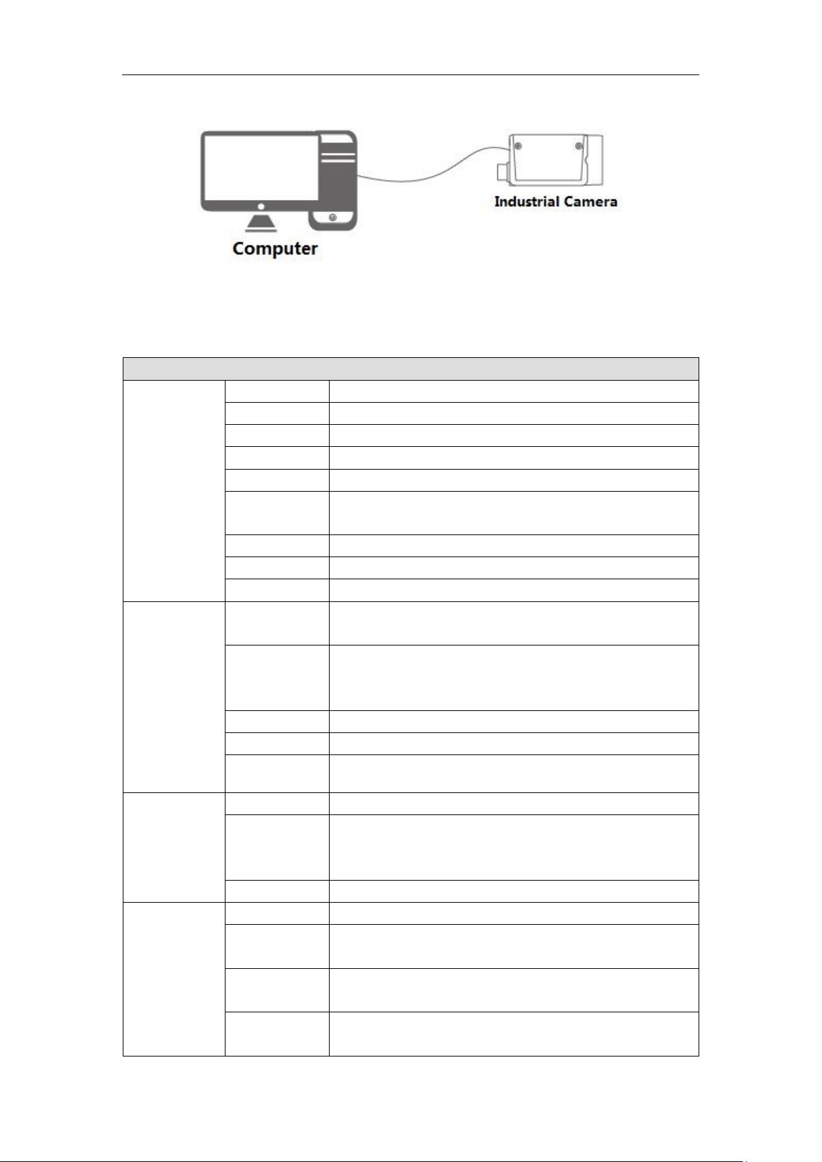
1.3 Typical Networking
The most typical networking mode of area scan camera is point-to-point connection,
which needs no other network medium between the host computer and industrial camera.
It can be connected through USB3 cable, please refer to Figure 1-1.
Product Overview 5
Page 6
A5031M/CU815 5000 series 0.3MP USB3 Mono/Color Area Scan Industrial Camera
Sensor
Sensor Model
PYTHON300
Sensor Type
CMOS
Mono/Color
Mono/Color
Shutter
Global
Resolution
640×480
Pixel Size
[μm]
4.8×4.8
Sensor Size
1/4"
Bit Depth
8/10
Frame Rate
815
Image
Dynamic
Range
60dB
Signal to
Noise Ratio
(SNR)
>38dB
Gain
0dB~18dB
Exposure Time
16μS~1S
Image Format
Mono:Mono8/10p;Color:BayerRG8/10p,BayerGB8/10p;
Physical
Interface
Data Interface
USB3.0
IO Interface
6-pin Hirose connector: 1 channel opto-isolated input, 1
channel opto-isolated output, 2 channel without
opto-isolation and configurable for input/output
Lens Mount
C
Power/Weight
Dimension/
Certification
Power Supply
Power supply via USB connector
Power
Consumption
≈3.4W
Temperature
Storage Temperature: -30 ℃ ~ +80 ℃ ; Operating
Temperature: -30℃~+50℃
Dimension
29mm×29mm×29mm(Not including the lens mount and
the rear case connectors)
Figure 1-1 Typical Networking
1.4 Main Technical Parameters
Product Overview 6
Page 7

A5031M/CU815 5000 series 0.3MP USB3 Mono/Color Area Scan Industrial Camera
Weight
60g
Certification
Conforms to CE,FCC,UL,RoHS,USB3Vision and
GenICam
Software
MV Viewer or GenICam and USB3Vision supported devices
A5051M/CU545 5000 series 0.5MP USB3 Mono/Color Area Scan Industrial Camera
Sensor
Sensor Model
PYTHON500
Sensor Type
CMOS
Mono/Color
Mono/Color
Shutter
Global
Resolution
800×600
Pixel Size
[μm]
4.8×4.8
Sensor Size
1/3.6"
Bit Depth
8/10
Frame Rate
545
Image
Dynamic
Range
60dB
Signal to
Noise Ratio
(SNR)
>38dB
Gain
0dB~18dB
Exposure Time
16μS~1S
Image Format
Mono:Mono8/10p;
Color:BayerRG8/10p,BayerGB8/10p;
Physical
Interface
Data Interface
USB3.0
IO Interface
6-pin Hirose connector: 1 channel opto-isolated input, 1
channel opto-isolated output, 2 channel without
opto-isolation and configurable for input/output
Lens Mount
C
Power/Weight
Dimension/
Certification
Power Supply
Power supply via USB connector
Power
Consumption
≈3.4W
Temperature
Storage Temperature : -30 ℃~+80 ℃;Operating
Temperature:-30℃~+50℃
Dimension
29mm×29mm×29mm(Not including the lens mount and
the rear case connectors)
Weight
60g
Certification
Conforms to CE,FCC,UL,RoHS,USB3Vision and
GenICam
Software
MV Viewer or GenICam and USB3Vision supported devices
Product Overview 7
Page 8

A5131M/CU210 5000 series 1.30MP USB3 Mono/Color Area Scan Industrial Camera
Sensor
Sensor Model
PYTHON1300
Sensor Type
CMOS
Mono/Color
Mono/Color
Shutter
Global
Resolution
1280×1024
Pixel Size
[μm]
4.8×4.8
Sensor Size
1/2"
Bit Depth
8/10
Frame Rate
210
Image
Dynamic
Range
60dB
Signal to
Noise Ratio
(SNR)
>38dB
Gain
0dB~18dB
Exposure Time
16μS~1S
Image Format
Mono:Mono8/10p;
Color:BayerRG8/10p,BayerGB8/10p;
Physical
Interface
Data Interface
USB3.0
IO Interface
6-pin Hirose connector: 1 channel opto-isolated input, 1
channel opto-isolated output, 2 channel without
opto-isolation and configurable for input/output
Lens Mount
C
Power/Weight
Dimension/
Certification
Power Supply
Power supply via USB connector
Power
Consumption
≈3.4W
Temperature
Storage Temperature : -30 ℃~+80 ℃;Operating
Temperature:-30℃~+50℃
Dimension
29mm×29mm×29mm(Not including the lens mount and
the rear case connectors)
Weight
60g
Certification
Conforms to CE,FCC,UL,RoHS,USB3Vision and
GenICam
Software
MV Viewer or GenICam and USB3Vision supported devices
A5201M/CU150 5000 series 2.0MP USB3 Mono/Color Area Scan Industrial Camera
Sensor
Sensor Model
PYTHON2000
Sensor Type
CMOS
Mono/Color
Mono/Color
Product Overview 8
Page 9

A5201M/CU150 5000 series 2.0MP USB3 Mono/Color Area Scan Industrial Camera
Shutter
Global
Resolution
1920×1200
Pixel Size
[μm]
4.8×4.8
Sensor Size
2/3"
Bit Depth
8/10
Frame Rate
150
Image
Dynamic
Range
60dB
Signal to
Noise Ratio
(SNR)
>38dB
Gain
0dB~18dB
Exposure Time
16μS~1S
Image Format
Mono:Mono8/10p;
Color:BayerRG8/10p,BayerGB8/10p;
Physical
Interface
Data Interface
USB3.0
IO Interface
6-pin Hirose connector: 1 channel opto-isolated input, 1
channel opto-isolated output, 2 channel without
opto-isolation and configurable for input/output
Lens Mount
C
Power/Weight
Dimension/
Certification
Power Supply
Power supply via USB connector
Power
Consumption
≈3.8W
Temperature
Storage Temperature : -30 ℃~+80 ℃;Operating
Temperature:-30℃~+50℃
Dimension
29mm×29mm×29mm(Not including the lens mount and
the rear case connectors)
Weight
60g
Certification
Conforms to CE,FCC,UL,RoHS,USB3Vision and
GenICam
Software
MV Viewer or GenICam and USB3Vision supported devices
A5501M/CU60 5000 series 5.0MP USB3 Mono/Color Area Scan Industrial Camera
Sensor
Sensor Model
PYTHON5000
Sensor Type
CMOS
Mono/Color
Mono/Color
Shutter
Global
Resolution
2592×2048
Pixel Size
[μm]
4.8×4.8
Product Overview 9
Page 10

A5501M/CU60 5000 series 5.0MP USB3 Mono/Color Area Scan Industrial Camera
Sensor Size
1"
Bit Depth
8/10
Frame Rate
60
Image
Dynamic
Range
60dB
Signal to
Noise Ratio
(SNR)
>38dB
Gain
0dB~18dB
Exposure Time
16μS~1S
Image Format
Mono:Mono8/10p;
Color:BayerRG8/10p,BayerGB8/10p;
Physical
Interface
Data Interface
USB3.0
IO Interface
6-pin Hirose connector: 1 channel opto-isolated input, 1
channel opto-isolated output, 2 channel without
opto-isolation and configurable for input/output
Lens Mount
C
Power/Weight
Dimension/
Certification
Power Supply
Power supply via USB connector
Power
Consumption
≈4.2W
Temperature
Storage Temperature : -30 ℃~+80 ℃;Operating
Temperature:-30℃~+50℃
Dimension
29mm×29mm×29mm(Not including the lens mount and
the rear case connectors)
Weight
60g
Certification
Conforms to CE,FCC,UL,RoHS,USB3Vision and
GenICam
Software
MV Viewer or GenICam and USB3Vision supported devices
A5402M/CU90 5000 series 4.0MP USB3 Mono/Color Area Scan Industrial Camera
Sensor
Sensor Model
CMV4000
Sensor Type
CMOS
Mono/Color
Mono/Color
Shutter
Global
Resolution
2048×2048
Pixel Size
[μm]
5.5×5.5
Sensor Size
1"
Bit Depth
8/10/12
Frame Rate
90
Image
Dynamic
60dB
Product Overview 10
Page 11

A5402M/CU90 5000 series 4.0MP USB3 Mono/Color Area Scan Industrial Camera
Range
Signal to
Noise Ratio
(SNR)
>38dB
Gain
0dB~54dB
Exposure Time
28.9μS~1S
Image Format
Mono:Mono8/10p;
Color:BayerRG8/10p,BayerGB8/10p;
Physical
Interface
Data Interface
USB3.0
IO Interface
6-pin Hirose connector: 1 channel opto-isolated input, 1
channel opto-isolated output, 2 channel without
opto-isolation and configurable for input/output
Lens Mount
C
Power/Weight
Dimension/
Certification
Power Supply
Power supply via USB connector
Power
Consumption
≈4.2W
Temperature
Storage Temperature : -30 ℃~+80 ℃;Operating
Temperature:-30℃~+50℃
Dimension
29mm×29mm×29mm(Not including the lens mount and
the rear case connectors)
Weight
60g
Certification
Conforms to CE,FCC,UL,RoHS,USB3Vision and
GenICam
Software
MV Viewer or GenICam and USB3Vision supported devices
A7500M/CU75 7000 series 5.0MP USB3 Mono/Color Area Scan Industrial Camera
Sensor
Sensor Model
IMX250
Sensor Type
CMOS
Mono/Color
Mono/Color
Shutter
Global
Resolution
2448×2048
Pixel Size
[μm]
3.45×3.45
Sensor Size
2/3"
Bit Depth
8/10/12
Frame Rate
75
Image
Dynamic
Range
70dB
Signal to
Noise Ratio
(SNR)
>38dB
Product Overview 11
Page 12

A7500M/CU75 7000 series 5.0MP USB3 Mono/Color Area Scan Industrial Camera
Gain
0dB~48dB
Exposure Time
33.6μS~1S
Image Format
Mono:Mono8/10p;
Color:BayerRG8/10p,BayerGB8/10p;
Physical
Interface
Data Interface
USB3.0
IO Interface
6-pin Hirose connector: 1 channel opto-isolated input, 1
channel opto-isolated output, 2 channel without
opto-isolation and configurable for input/output
Lens Mount
C
Power/Weight
Dimension/
Certification
Power Supply
Power supply via USB connector
Power
Consumption
≈4.2W
Temperature
Storage Temperature : -30 ℃~+80 ℃;Operating
Temperature:-30℃~+50℃
Dimension
29mm×29mm×29mm(Not including the lens mount and
the rear case connectors)
Weight
60g
Certification
Conforms to CE,FCC,UL,RoHS,USB3Vision and
GenICam
Software
MV Viewer or GenICam and USB3Vision supported devices
1.5 Spectral Curve
The following spectral curve data are derived from the manual of the selected chip.
Product Overview 12
Page 13
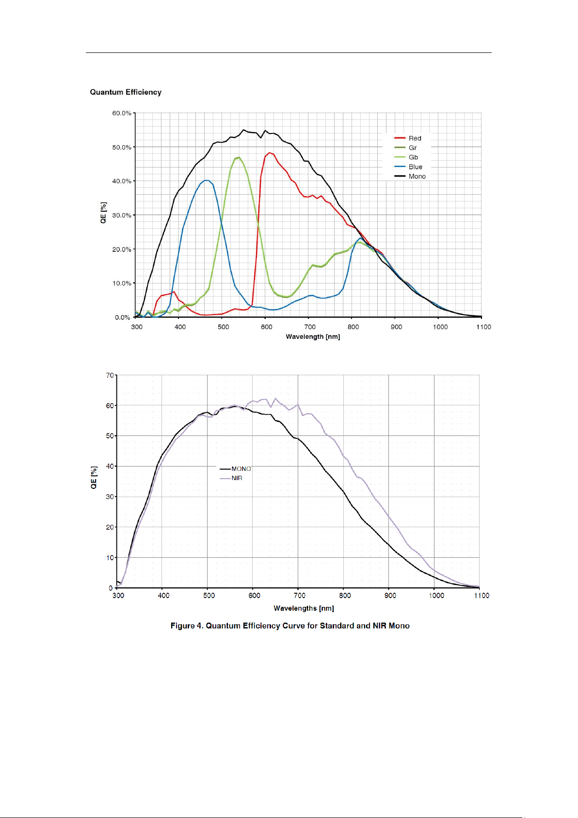
Figure 1-2 PYTHON 300/ PYTHON 500/ PYTHON 1300 Mono/Color Spectral Response
Figure 1-3 PYTHON 1300 Mono/NIR Spectral Response
Product Overview 13
Page 14
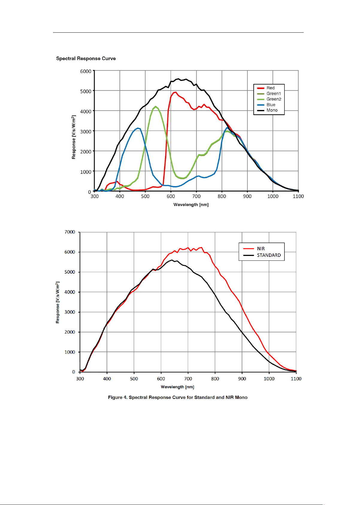
Figure 1-4 PYTHON 2000/ PYTHON 5000 Mono/Color Spectral Response
Figure 1-5 PYTHON 2000/ PYTHON 5000 Mono/NIR Spectral Response
Product Overview 14
Page 15
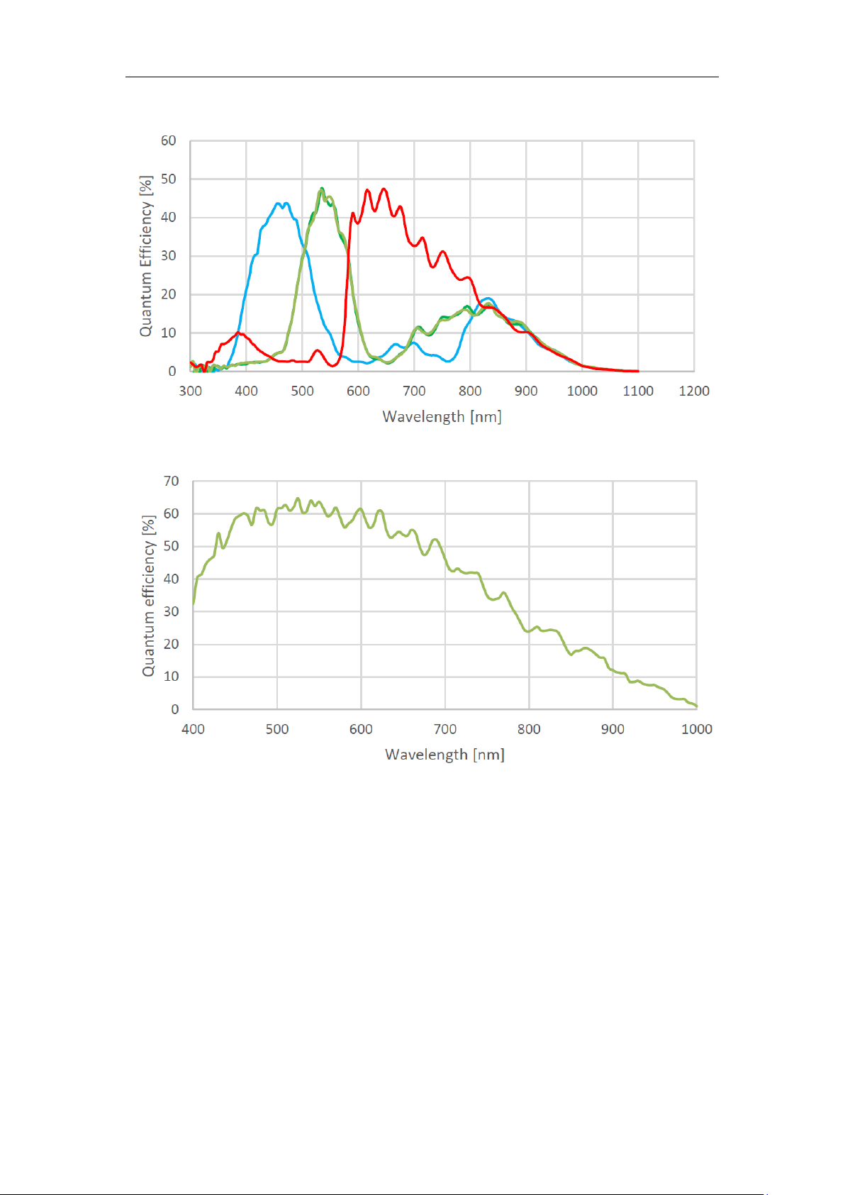
Figure 1-6 CMV4000 Color Spectral Response
Figure 1-7 CMV4000 Mono Spectral Response
Product Overview 15
Page 16
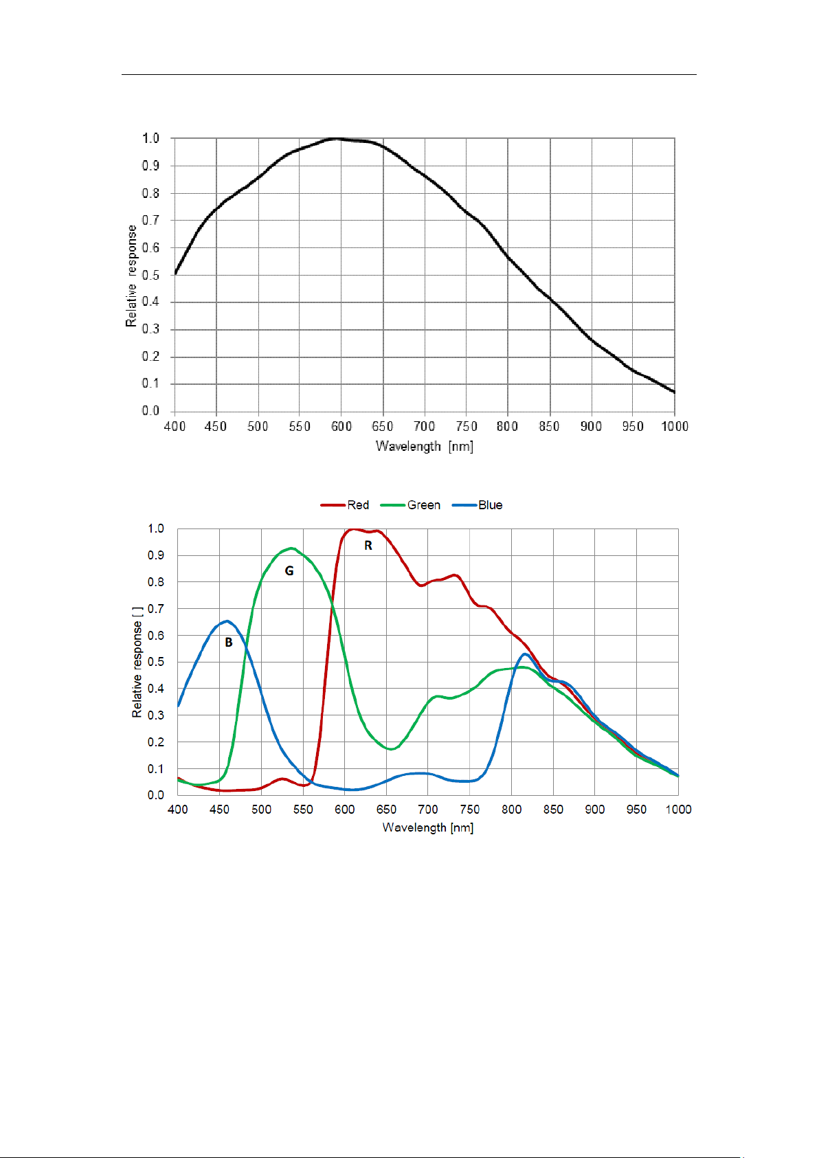
Figure 1-8 IMX250 Mono Spectral Response
Figure 1-9 IMX250 Color Spectral Response
1.6 Environmental Requirements
The following are the environmental requirements for USB3 area scan industrial
camera:
Temperature and humidity
Ambient temperature should not exceed 50 ℃ , it is best to work in an
air-conditioned environment.
Product Overview 16
Page 17

Operating cover temperature:0℃~60℃.
Operating ambient humidity:20%~80% no condensation.
Storage temperature:-30℃~+80℃.
Storage humidity:20%~80% no condensation.
Please install the device in a stable location indoors, with enough heat dissipation
space.
Please keep certain ventilation.
Product Overview 17
Page 18

2.1 Product Dimensions
The product dimensions are as follows:
Figure 2-1 29mm×29mm×29mm(Unit:mm)
2 Interface Description
Figure 2-2 Dimensions of Installation Block
Interface Description 18
Page 19

2.2 Interface Description
Pin
Signal
Description
1
Line3
GPIO(Non-isolated software can configure input and
output)
2
Line1
Opto-coupler isolation input
3
Line2
GPIO(Non-isolated software can configure input and
output)1
4
Line0
Opto-coupler isolation output
5
ISO_GND
Opto-coupler isolation signal ground(ISO_GND)
6
GND
GPIO signal ground(GND)
The back of the device has two interfaces, the network interface and 6pin power as well as I/O interface,
as shown below:
Figure 2-3 Interface Description
2.2.1 USB Port
USB port supports USB2.0 and USB3.0,which can be used in camera control, data transmission and power
supply.
To ensure the transmission quality, please use certified cables to prevent too much data retransmission and packet
loss.
2.2.2 I/0 Port
Sheet 2-1 Pin Signal Definition
Interface Description 19
Page 20

Parameter
Description
Power Specification
+5.0V power supply via USB3.0 port(Conforms to USB3.0 interface specification)
EMS Standard
Electrostatic discharge(GBT17626.2/IEC61000-4-2)
Metal cover contact 6kV
EMC Standard
Class B
Input Voltage
Description
DC30V
Limit voltage: input voltage should not exceed this limit, otherwise it will
cause damage to the device
DC0~24V
I/O input safe operating voltage range
DC0~1.4V
Indicates logical 0
DC>1.4V~2.2V
Input state reverses and logic state is not certain
DC>2.2V
Indicates logical 1
Voltage
Description
Note
DC 0~30V
I/O output swing range, 30V is limit
If the output of the camera is connected with
2.3 Electrical Specification
2.3.1 Power and USB Port Electrical Specifications
Sheet 2-2 Power and USB Port Electrical Specifications
2.3.2 IO Port Electrical Specification
2.3.2.1 Opto-isolated Input
Sheet 2-3 Opto-isolated Input
Isolated I/O input sink current is 5mA~15mA.
2.3.2.2 Opto-isolated Output
Figure 2-4 Opto-isolated Input Circuit
Sheet 2-4 Opto-isolated Output
Interface Description 20
Page 21

Voltage
Description
Note
voltage which should not be exceeded,
otherwise it will cause damage to the
device
an inductive load such as intermediate relay,
please use the built-in freewheeling diode or
the output interface will be damaged.
DC<3.3V
I/O output may go wrong if logical 1 has
been set within this range, it is advised
to use 0V to indicates logical 0
DC3.3V~+24V
Any voltage within this range can be
used to indicates logical 1, it is defined
by user
Voltage
Description
DC30.0V
Limit voltage: input voltage should not exceed this limit, otherwise it will cause
damage to the device
DC0~5.0V
Input safe operating voltage range(the min voltage is DC 3.3V when pulled-up
from external)
DC0~0.8V
Indicates logical 0
DC>0.8V~2.0V
Input state reverses and logic state is not certain
DC>2V
Indicates logical 1
The max continuous current of isolated I/O output is 50mA.
Figure 2-5 Opto-isolated Output Circuit
2.3.2.3 GPIO Input
The user's external circuit must be able to sink a maximum current of 2mA while the voltage does not
exceed DC 0.8V. The sink current of the interface should be less than 100uA when input voltage is a
high level.
Sheet 2-5 GPIO Input
Interface Description 21
Page 22

Voltage
Description
DC 0~30V
I/O output swing range, 30V is limit voltage which should not be
exceeded, otherwise it will cause damage to the device
DC+3.3V~+24V
Any voltage within this range can be used to indicates logical 1, it is
defined by user
DC<3.3V
I/O output may go wrong if logical 1 has been set within this range,
it is advised to use 0V to indicates logical 0
Figure 2-6 GPIO Input Circuit
Figure 2-7 Input Circuit of 5V TTL Logic Level
2.3.2.4 GPIO Output
Sheet 2-6 GPIO Output
The max sink current of isolated I/O output is 50mA.
Interface Description 22
Page 23

Status
Indicator light status
Note
Normal
Red
Red light quick flashing
Device booting.
Blue
Blue light high brightness
The application software API is connected to the
device, free mode, no image transmission.
Blue light quick flashing
The application software API is connected to the
device, free mode, with image transmission.
Blue light slow flashing
Use trigger mode.
Red
Blue
Red and blue light alternate
flashing
Firmware upgrading.
Abnormal
Red
Red light normally on
Device abnormity: such as no stream, firmware
upgrade failure and etc.
Figure 2-8 GPIO Output
2.4 Indicator Light Description
The indicator light description of the device is shown in Sheet 2-7.
Sheet 2-7 Indicator Light Description
Interface Description 23
Page 24

Installation is divided into hardware installation and application installation.
No.
Accessory
Number
1
Area Scan Camera
1
2
Installation Structure
1
3
M2×6 Screw
4
4
M3×8 Screw
3
3.1 Hardware Installation
Before installation, please check the device whether there is any obvious damage, and confirm with the
list of default accessories.
3.1.1 Default Accessories
3 Product Installation
The list of default accessories is shown in Sheet 3-1.
Sheet 3-1 Accessory List
3.1.2 Camera Installation
When installing, the static, electromagnetic interference, lightning and surge should be considered, and
at the same time, the combined camera heat dissipation should also be concerned.
3.1.2.1 Consideration of Static, Electromagnetic Interference, Lightning and Surge
Although the camera has a lightning and anti-surge protection design, as well as EMI (Electro-Magnetic
Interference) and ESD (Electro-Static Discharge) protection design, but for security, the installation
environment and methods should be concerned to avoid or reduce these effects.
Please pay attention to basic protection methods shown below:
Please use shielded lines as power control cord and avoid winding. The power cord and the
network cable can be run in parallel, but do not wrap them together.
Power cord and USB cable should be far away from high current, high voltage, frequently on-off
devices, such as stepper motors. In particularly, do not route power cord and network cable with
Product Installation 24
Page 25

such devices in parallel because such devices have strong electro-magnetic radiation which is easy
to couple to the camera's transmission line.
Shelter grounds of all devices must be connected together and take single point grounding.
Multi-point grounding easily leads to voltage difference between devices which form circuits to
induce couple electro-magnetic interference.
Power supply for camera and that for PC must be from the same AC power distributor in order to
connect their shelter grounds and avoid multi-point grounding. High-power mechanical and
electrical equipment do not directly use this AC power.
Magnetic ring can be added to the power control cord of camera in order to absorb
electro-magnetic interference signals.
Please keep the suitable humidity and operate with wrist strap, anti-static clothes and shoes to
reduce ESD.
3.1.2.2 Heat Dissipation
Under the condition of a stable condition (temperature and humidity, air flow, installation location, etc.)
the camera will reach a temperature balance in 1 or 1.5 hours, which means that the cover temperature
will not rise any longer. It is important to ensure the cover temperature beyond 50℃ and there is a
temperature difference of 25℃ between inner main heat source and outside cover in this balanced
condition. When the cover temperature is under 50℃, the electronic chip inside will not suffer damage.
Recommend several good methods of controlling the temperature:
Ambient temperature should be beyond 30℃, it is best to work in an air-conditioned environment.
Installed on the object with good thermal conductivity, such as large metal which is easy to
dissipate heat.
Ensure certain air flow to dissipate heat.
3.2 Software Installation
Application installation steps of host computer are as follows:
Step1 Turn the PC on.
Step2 Double client the installation package and install MV Viewer program according to the prompt
on the interface. You can see Figure 3-1 after installation.
Please get in touch with relevant technical supporter to obtain the installation package.
Product Installation 25
Page 26

Figure 3-1 Installation Completion
Product Installation 26
Page 27

4 Network Settings
Please make sure that USB area scan camera is properly connected to the PC.
Please install the application in the PC. If have any problems, please refer to ―3.2 Software
Installation‖ for details.
When the camera is well connected with cables, the application installed can detect the online camera.
The detailed steps for network settings are as follows:
Step1 Client installation.
Double client the installation package and install MV Viewer program according to the prompt
on the interface. You can see Figure 4-1 after installation.
Figure 4-1 Installation Completion
Step2 Open software.
Double click desktop shortcut , open client software. The software will auto detect all
Network Settings 27
Page 28

the online devices, the interface is shown in Figure 4-2.
Figure 4-2 Software Interface
Step1 Device connection.
Click to connect the device. Click after successful connection, the device
interface and property interface are shown in Figure 4-3 and Figure 4-4 respectively.
You can click to disconnect the device.
Network Settings 28
Page 29

Figure 4-3 Successful Device Connection(Device Interface)
Figure 4-4 Successful Device Connection(Property Interface)
Network Settings 29
Page 30

No.
Parameter Description
1
Please refer to Sheet 4-2 for more details about the menu column.
2
It is to detect the device list of all the online devices, which are GigE, USB and
CameraLink.
:Refresh, click the icon and manually refresh the info of online device.
:It means the device is in a connectable state.
:It means the device is in a non-connectable state; please make sure USB3 drive has
been installed.
:It means the device is in a connected state. MV Viewer can only connect and operate
one camera.
3
It is to select port info and device info displayed by some device.
4
The setup info of the current image, which includes video stream, image stream, display
stream, image location, gray level and RGB color value, etc.
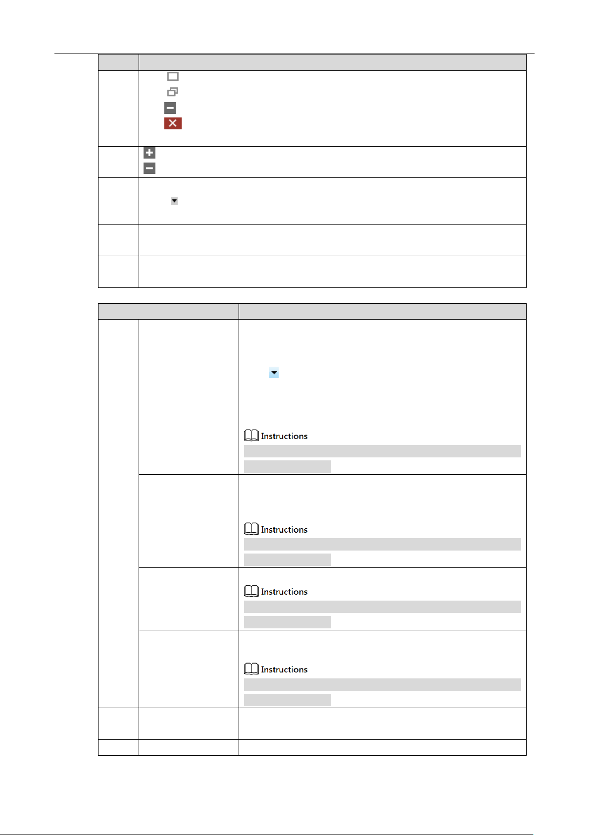
5
It is to play the adjustment toolbar of the image.
:Play Button. You can click according to your needs, and select play mode
of continuous, single-frame and multi-frame in the drop-down list.
Only when the image is paused can you switch the play mode in the drop-down list.
:Stop button.
:Save picture.
:Zoom in button; it is to zoom in the display image.
:Zoom out button; it is to zoom out the display image.
:Display the image in 100%.
:Display the video image according to the window size.
Click the icon to display video image according to the window size when the image
is zoomed in or out.
:Up and down mirror for the image.
:Left and right mirror for the image.
Sheet 4-1 Parameter Description
Network Settings 30
Page 31
No.
Parameter Description
6
:Maximize the window.
:Restore the window size downwards.
:Minimize the window.
:Close the application.
7
:It is to display all the combined parameter info.
:It is to combine all the displayed parameter info.
8
Parameter visibility.
Click according to your needs. Select Beginner, Expert or Guru in the drop-down
menu. The corresponding parameter items of each level are slightly different.
9
The parameter items of different role of the camera, Figure 4-4 shows the parameter items
in the expert role.
10
Parameter explanation area.
Click some parameter item, and it will display the explanation of the parameter.
Menu
Note
File
Open file
Implement the order of ―File > Open File‖, pop out a dialogue box
of ―Open‖ to open it.
It is not convenient to search if there are so many files. You can
click button of ―File Type‖ on the right and select a specific
file format in the drop-down menu(such as mvcfg). The dialogue
box will only display the file of this format, which is to narrow
search range.
It can implement corresponding operations only when the image
is paused or stopped.
Open recent files
―File > Open the Recent Files‖ submenu includes 10 files which
have been recently used in MV Viewer. Click a file name and you
can open it directly.
It can implement corresponding operations only when the image
is paused or stopped.
Save
Save the modification upon the current file.
It can implement corresponding operations only when the image
is paused or stopped.
Save as
Save the current file into another location with another name, you
can use the order of ―File > Save As‖.
It can implement corresponding operations only when the image
is paused or stopped.
Event
Event notice
It includes device parameter update, event message channel and
pull stream cache, etc.
Picture
Save picture
Save the video stream data as picture file.
Sheet 4-2 Menu Column—Parameter Explanation
Network Settings 31
Page 32

Menu
Note
Save current picture
Save the video stream data of last frame as picture file.
Config
Connection control
It is to set the time of connection timeout and detection interval.
Cache option
It is to set the cache parameter of video stream data.
It can implement corresponding operations only when the image
is paused or stopped.
Display frame rate
It is to display the frame rate of current image.
Display block data
It is to display the total frame quantity acquired in the current
trigger mode.
Restore default
parameter
It is to restore the default config of the menu bar.
Save GenICamXML
Save GenICam protocol in XML language.
Language
Select language, Chinese or English.
Help
User manual
Check the user manual of the current software.
About software
Check the version info of current software.
Network Settings 32
Page 33

5 Main Function Description
This chapter mainly introduces function parameters related to industrial camera. Please refer to
"Properties" interface in MV Viewer for details of parameter information.
Industrial camera supports three user levels which are Beginner, Expert and Guru. The parameter
items in corresponding property interface of each level are slightly different. Please refer to No.9 in
Sheet 4-1 for user level selection.
The parameter items displayed in black indicate that the parameter can be changed or set. The
parameter items displayed in gray indicate that the parameter does not support change or setting in
the current operating mode.
Main Function Description 33
Page 34

Format
Exposure
Gain
Blacklevel
WhiteBalance
Mono Y Y
Y
/
Bayer Y Y
Y
Y
Disable
Function
/
Set GainRaw
to 1
Set BlackLevelAuto to
Off; set BlackLevel to 0
Set BalanceWhiteAuto to Off; select
Red, Green or Blue in
BalanceRatioSelector and set
BalanceRatio to 1
Format
Gamma
LUT
Sharpness
Denoising
Mono Y Y
Y
Y
Bayer Y Y
Y
Y
Disable
Function
Set
Gamma to
1
Set
LUTEnable to
False
Set SharpnessEnabled to
Off
Set Denoising to Disable
Format
Contrast
DigitalShift
Brightness
Mono Y Y
Y
Bayer / Y
Y
Disable
Function
Set
Contrast to
50
Set
DigitalShift to
0
Set Brightness to 50
Functions of ISP module for different image formats are shown in Sheet 5-1:
Sheet 5-1 Functions of ISP Module for Different Image Formats
5.1 DeviceControl
You can check the device information and change the device name in Property, as shown in Figure 5-1;
please refer to Sheet 5-2 for parameter setting details.
Main Function Description 34
Page 35

Parameter
Explanation
DeviceScanType
The scan type of the sensor: area scan / line scan.
DeviceVendorName
Device vendor name.
DeviceModelName
Device model name.
DeviceFamilyName
Device series.
DeviceManufacturerInfo
Device manufacturer info.
DeviceVersion
Device version, including updated date and SVN number in the bracket.
DeviceFirmwareVersion
Device firmware version, including updated date and SVN number in the
bracket and the number following the semicolon represents the hardware
version.
DeviceSerialNumber
Device serial number.
DeviceUserID
User-programmable device identifier.
DeviceTLType
The protocol type used by the camera transport layer: confirms to
GigEVision/CameraLink/CameraLinkHD/CoaXPress/USB3Vision.
DeviceSFNCVersionMajor
The major version of SFNV supported by the device.
Figure 5-1 Device Control
Sheet 5-2 Device Control—Parameter Explanation
Main Function Description 35
Page 36

Parameter
Explanation
DeviceSFNCVersionMinor
The minor version of SFNV supported by the device.
DeviceLinkThroughputLimitMode
Enables the bandwidth limit function.
DeviceLinkThroughputLimit
The value of bandwidth limit.
DeviceReset
Device reset button which can restart the camera by calling API.
DeviceTemperatureSelector
Select to view the temperature of sensor board / mainboard.
DeviceTemperature
The actual temperature of sensor board / mainboard (℃) .
DeviceUSBMode
The current connected USB mode, such as USB3.0.
5.2 ImageFormatControl
In this property, you can change image size, image pixel format, region of interest(ROI) and test image
mode etc., as shown in Figure 5-2; please refer to Sheet 5-3 for more details about parameter settings.
Please refer to 1.4 Main Technical Parameters for the image output formats supported by the industrial
camera. Specific supported formats are subject to the formats supported by the camera.
Figure 5-2 Image Format Control
Main Function Description 36
Page 37

Parameter
Explanation
SensorWidth
Sensor raw image width in pixels.
SensorHeight
Sensor raw image height in pixels.
WidthMax
Maximum width of the image (in pixels), which will be affected by
decimation, etc.
HeightMax
Maximum height of the image (in pixels), which will be affected by
decimation, etc.
Width
The actual output image width (pixels).
Height
The actual output image height (pixels).
OffsetX
The horizontal offset of the image from the top left. The max value is
determined by the Width value.
OffsetY
The vertical offset of the image from the top left. The max value is
determined by the Width value.
ReverseX
Flip the image horizontally based on the original size of the sensor but
not the image after ROI.
ReverseY
Flip the image vertically based on the original size of the sensor but
not the image after ROI.
If the output format of the color type is Bayer, the image format needs
to be modified after reversing vertically to interchange BayerRGxxx
and BayerGBxxx.
PixelFormat
Image output format. Different models support different formats.
PixelSize
Total size in bits of a pixel of the image.
PixelColorFilter
Type of color filter that is applied to the image in the current image
output format.
Only the color camera has this property.
PixelDynamicRangeMin
The min image pixel brightness.
PixelDynamicRangeMax
The max image pixel brightness.
TestImageSelector
Selects the test image type: Disable、TestImage1(Static Image)or
TestImage2(Dynamic Image).
The test image is not an actual image and is used for testing purposes
only.
Decimation
Output Image Decimation Type: X for Horizontal, Y for Vertical, and
XY for Horizontal Vertical.
Pay attention to that when Decimation is on, the max output image will
be affected and the frame rate will be improved. The frame rate will
Sheet 5-3 Image Format Control – Parameter Explanation
Main Function Description 37
Page 38

5.3 AcquisitionControl
Parameter
Explanation
AcquisitionMode
Image acquisition mode:
SingleFrame: acquires one frame at a time and stops to
capture frames automatically when finished.
MultiFrame: acquires frames specified by
AcquisitionFrameCount and stops to capture frames
automatically when finished.
Continue: acquires frames continuously until an Acquisition
Stop signal is given to stop to capture frames.
AcquisitionStart
SDK starts / stops to capture frames.
AcquisitionStop
not be improved when Decimation is on in CCD type.
In this property, you can set the image acquisition mode, trigger mode and exposure time etc., as shown
in Figure 5-3; please refer to Sheet 5-4 for detailed parameter settings.
Figure 5-3 Acquisition Control
Sheet 5-4 Acquisition Control - Parameter Explanation
Main Function Description 38
Page 39

Parameter
Explanation
AcquisitionFrameCount
Number of frames to acquire.
It is invalid to change this parameter when image acquisition mode
is SingleFrame or Continue. You can set the acquisition frame
count in MultiFrame mode.
AcquisitionFrameRate
Acquisition frame rate.
The frame rate set in AcquisitionFrameRate is valid only when
AcquisitionFrameRateEnable is True.
If the frame rate is set beyond the max frame rate
(ResultingframeRateAbs) in the current mode, the actual frame rate
of the camera is ResultingframeRateAbs, not the value set by
AcquisitionFrameRate.
AcquisitionFrameRateEnable
AcquisitionStatusSelector
Selects which trigger status to view.
Selects AcquisitionTriggerWait or FrameTriggerWait in
AcquisitionStatusSelector and views in AcquisitionStatus: True is
for waiting for a trigger and False for having triggered.
AcquisitionStatus
TriggerSelector
Selects the trigger type.
Selects FrameStart or AcquisitionStart in TriggerSelector and select
On/Off in TriggerMode to enable/disable the trigger mode. You
need to trigger AcquisitionStart at first when triggering together,
then you can trigger FrameStart to acquire frames.
TriggerMode
TriggerSoftware
Trigger mode.
TriggerSource supports SoftwareTrigger and lineN
(HardwareTrigger).
When you select SoftwareTrigger, click or call API in
TriggerSoftware to generate software trigger.
When you select lineN, set RisingEdge or FallingEdge in
TriggerActivation, then the external cable generates a rising or
falling signal to achieve hardware trigger.
You can separately select trigger source for AcquisitionStart and
FrameStart.
TriggerSource
TriggerActivation
TriggerDelay
Trigger delay.
Indicates the time between when the camera receives the trigger
signal and when the trigger takes effect. It is valid for both soft
trigger and hard trigger.
LightTriggerDelay
It is used to set the delay time between when the camera receives
the trigger signal and when LightTrigger takes effect to control the
opto-coupler conduction. Opto-coupler conduction time is when
LightTrigger starts to the end of the exposure.
During the delay, the camera can’t receive a new trigger, otherwise
Main Function Description 39
Page 40

Parameter
Explanation
it will be abnormal and needs to stop the frame capture and restart
to return to normal.
ExposureMode
Exposure mode: supports Timed mode and TriggerWidth mode.
Timed: exposure time is set in ExposureTime.
TriggerWidth: exposure time is the external trigger pulse
width.
Some models do not support TriggerWidth mode.
ExposureTime
Exposure time.
ExposureAuto
Exposure automatically.
Off means the function is disabled. You can set exposure time
in ExposureTime with a range of 0us~1000000us.
Once means the camera can modify the exposure time once
according to the ambient brightness. The modified value is
displayed in gray in ExposureTime.
Continue means the camera can continuously modify the
exposure time according to the ambient brightness. The
modified value is displayed in gray in ExposureTime.
ResultingframeRateAbs
The max frame rate the camera can achieve.
The max frame rate the camera can achieve depends on the
network transmission bandwidth, pixel size, resolution and
exposure time. The camera default exposure time takes precedence,
which means that when the exposure time is greater than the
reciprocal of the frame rate, the frame rate is preferentially reduced
instead of limiting the max exposure time.
5.4 DigitalIOControl
In this property, you can control different I/O input or output signals, as shown in Figure 5-4; please
refer to Sheet 5-5 for detailed parameter settings.
Main Function Description 40
Page 41

Parameter
Explanation
LineSelector
Selects the external IO line for configuration.
LineMode
Configures the output mode of selected IO Line:Input/Output.
LineInverter
Controls the selected physical input or output line signal inversion,
True is for the signal to invert, False for the signal not to invert.
LineStatus
Indicates the current status of the selected physical input or output
line.
LineStatusAll
Returns the current status of all available lines.
LineSource
When IO line is selected to be the output, you can select the trigger
source. Current supported trigger sources are as follows:
ExposureActive: outputs the signal when exposure starts.
FrameTriggerWait: outputs the waiting signal for frame trigger.
Timer0Active: outputs the signal when the Timer0 counts up.
UserOutput0: outputs the value user set in Userset0.
AcquisitionTriggerWait: outputs the waiting signal for
acquisition trigger.
LightTrigger: outputs the light trigger signal.
Output 1 means the opto-coupler is on, 0 means off.
LineFormat
Shows whether the currently selected IO line supports opto-coupler
isolation.
UserOutputSelector
User-defined output group selection.
UserOutputValue
The output value of the user-defined output group.
UserOutputValueAll
Sets all values of the user-defined output group to 0 or 1.
Figure 5-4 Digital IO Control
Sheet 5-5 Digital IO Control - Parameter Explanation
Main Function Description 41
Page 42
Parameter
Explanation
LineDebouncerTimeAbs
When IO line is selected to be the input, you can set the debouncer
time.
A pulse less than the set value will not be considered as a valid
trigger input.
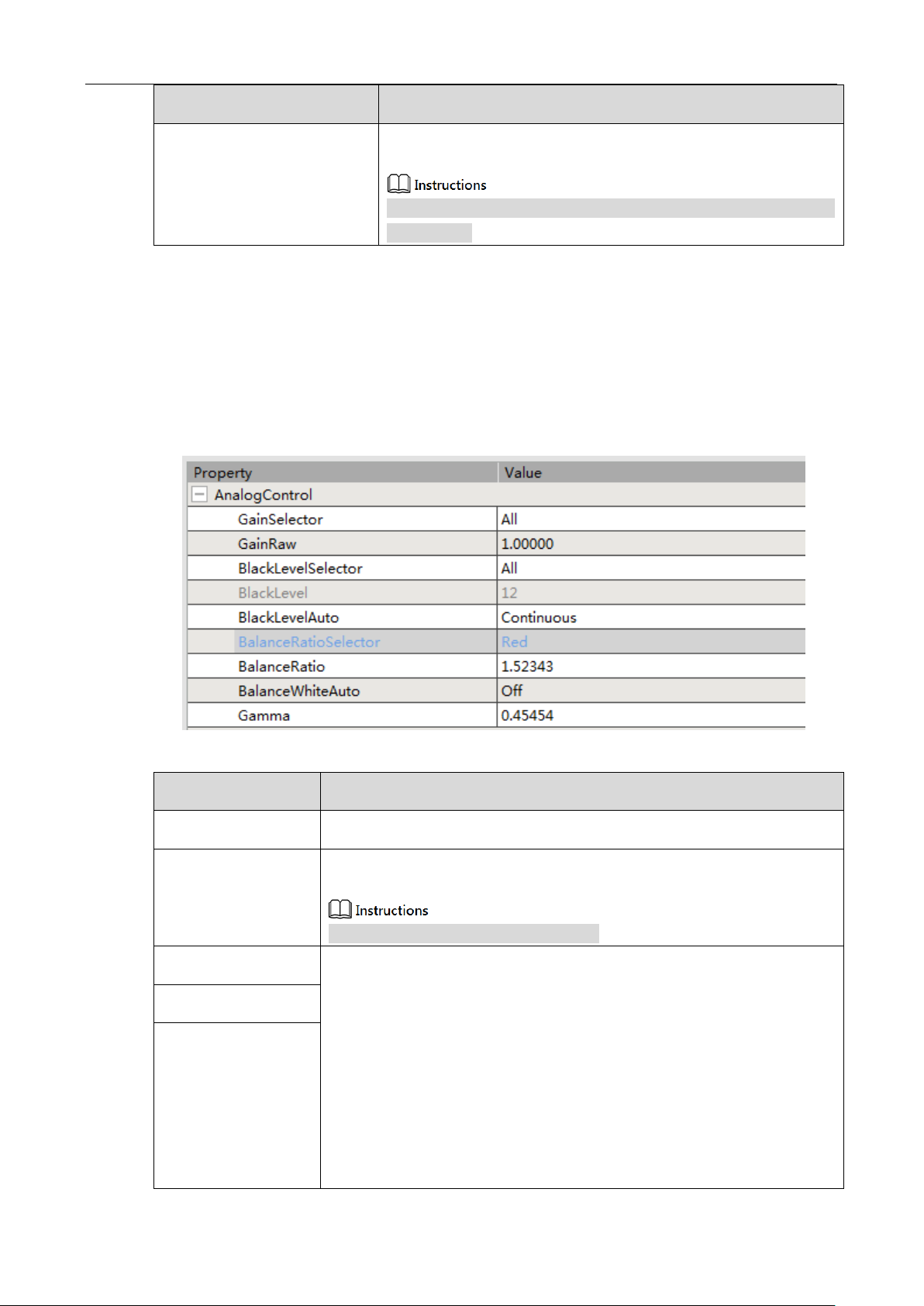
5.5 AnalogControl
Parameter
Explanation
GainSelector
The channel gain is not supported to set, the default is All.
GainRaw
The larger the gain, the brighter the image. The set range is different for
different types and the default value is 1.
The analog gain is preferentially enabled.
BlackLevelSelector
BlackLevelSelector is used to select the black balance channel.
BlackLevel is used to eliminate the impact of Sensor’s dark current. The dark
current is a phenomenon that the image brightness is a value greater than 0
when it is all black. By modifying the black level value, the brightness of the
channel can be more responsive to the actual image brightness. The setting
range is 0 ~ 255.
When BlackLevelAuto is set as Off, the fixed black level that the
algorithm minus is 1/4 of the value set in BlackLevel.
When BlackLevelAuto is set as Once, it will automatically set
BlackLevel for once according to the return value of sensor. Then it will
BlackLevel
BlackLevelAuto
In this property, you can adjust the acquired analog signals, including gain , black balance, white
balance and gamma correction etc., as shown in Figure 5-5; please refer to Sheet 5-6 for detailed
parameter settings.
Figure 5-5 Analog Control
Sheet 5-6 Analog Control - Parameter Explanation
Main Function Description 42
Page 43

Parameter
Explanation
change to be Off.
When BlackLevelAuto is set as Continues, it will continuously set
BlackLevel according to the return value of sensor.
Black level will change when the temperature rises. It is recommended to
capture a more accurate black level when the temperature is constant.
BalanceRatioSelector
Selects Red, Green or Blue channel to set white balance.
Adjusts the image color through adjusting R/G/B, in order to achieve a
highest color reproduction.
When BalanceRatioSelector is set as Off, it represents manual white
balance mode. User can manually set Red, Green, Blue channel values
in BalanceRatio.
When BalanceRatioSelector is set as Once, it represents auto white
balance mode for once. Auto white balance mode will operate for a
period and then stops according to the current scene. An algorithm for
searching gray region is used to find possible gray region in Bayer data.
When BalanceRatioSelector is set as Continues, it represents continuous
white balance mode.
White balance correction is only available for the color camera. White
balance of the mono camera defaults to 1.
BalanceRatio
BalanceWhiteAuto
Gamma
Gamma value setting.
It is a non-linear correction for image data to correct the non-linear response
of the monitor. The larger the Gamma value, the brighter the image.
The Gamma value setting range is 0~3.99998. The default value is 1 with
no Gamma process.
5.6 LUTControl
In this property, you can stretch and highlight the gray-level range of the region of interest. The
operation applies to linear curve as well as customized mapping curve, as shown in Figure 5-6; please
refer to Sheet 5-7 for detailed parameter settings.
LUT: short for Look-Up Table.
LUT and Gamma are mutually exclusive. If Gamma is enabled, LUT will not take effect. If LUT is
enabled, Gamma needs to be set to 1.
Main Function Description 43
Page 44

Parameter
Explanation
LUTSelector
Selects the channel of LUT.
Currently only Luminance(brightness)Look-Up Table is supported.
LUTEnable
LUT setting.
1. Enables LUT for LUT lookup table function.
2. Sets digital points of the lookup table in LUTIndex with range of
0~4095.
3. When LUTIndex is selected, you can set corresponding values in
LUTValue.
LUTIndex
LUTValue
LUTValueAll
Sets all the values of Index to the same value.
Parameter
Explanation
PayloadSize
The number of bytes transferred for each image or
chunk on the stream channel.
GevTimestampTickFrequency
Defines the tick frequency of the timestamp.
U3vCurrentSpeed
Current connection speed of the camera.
Figure 5-6 LUT Control
Sheet 5-7 LUT Control - Parameter Explanation
5.7 TransportLayerControl
In this property, you can set parameters related to camera’s transport layer protocol, as shown in Figure
5-7; please refer to Sheet 5-8 for detailed parameter settings.
Figure 5-7 Transport Layer Control
Sheet 5-8 Transport Layer Control - Parameter Explanation
Main Function Description 44
Page 45

5.8 UserSetControl
Parameter
Explanation
UserSetSelector
UserSetSelector: supports Default, UserSet1 and UserSet2.
Selects which series to use for the subsequent UserSetLoad and UserSetSave
operation.
UserSetLoad: restores the camera configuration to the configuration that user
selected.
UserSetSave: saves the current configuration to the selected series, but the
Default series does not support saving.
UserSetLoad
UserSetSave
UserSetDefault
Default user set when the power is on. UserSet1 and UserSet2 need to
execute UserSetSave before display.
UserSetLoadLastUserSet
The last user configuration the user used.
UserSetLoadStatus
User set load status.
Displays whether the configuration has been successfully loaded.
In this property, you can save or load the parameter scheme set by user and set the default parameter
configuration when opening the client, as shown in Figure 5-8; please refer to Sheet 5-9 for detailed
parameter settings.
Sheet 5-9 User Set Control - Parameter Explanation
Figure 5-8 User Set Control
5.9 CounterAndTimerControl
In this property, the counter can divide the frequency of the external input trigger signal and execute
exposure control according to the user’s logic, as shown in Figure 5-9; please refer to Sheet 5-10 for
detailed parameter settings.
Please set TriggerSource in 5.3 AcquisitionControl before using.
Main Function Description 45
Page 46

Parameter
Explanation
CounterSelector
Selects the counter which needs to configure:Counter0 or Counter1.
If Counter0 is selected,CounterEventSource displays FrameTrigger.
If Counter1 is selected,CounterEventSource displays FrameStart.
CounterResetSource
Selects the signal source to reset the counter:non-reset Off、software signal
reset SoftwareSignal0 and hardware signal reset Line1.
CounterEventSource
Select the events that will be the source to increment the Counter:
FrameTrigger/FrameStart.
CounterReset
The selected counter used for software reset.
TimerSelector
Selects the counter needs to configure. The default is Timer0.
TimerTriggerSource
Selects the trigger source of the start timer. The default is ExposureStart.
TimerTriggerActivation
Selects the trigger mode of the start timer: RisingEdge, FallingEdge or
AnyEdge.
TimerDelay
Sets start timer delay when receiving the trigger.(μs)
TimerDuration
Sets the duration of the timing pulse.(μs)
Figure 5-9 Counter and Timer Control
Sheet 5-10 Counter and Timer Control - Parameter Explanation
5.10 ISPControl
In this property, you can adjust the image sharpness, brightness, saturation, contrast and so on, as shown
in Figure 5-10; please refer to Sheet 5-11 for detailed parameter settings.
Hue and saturation are only available for the color camera.
Main Function Description 46
Page 47

Parameter
Explanation
SharpnessEnabled
Sets sharpness enable.
Sharpness
Sets image sharpness.
DenoisingMode
Sets image denoising mode.
When Disable is selected, no denoising process is performed.
When Bilateral is selected, it uses Bilateral algorithm to denoise.
Denoising
When Bilateral is selected, the level of denoising can be set.
DigitalShift
Adjusts DigitalShift. The brightness can be doubled when the value increases
by one.
Brightness
Brightness.
Adjust the brightness value of the exposure target. The default value is 50.
The greater the value, the brighter the image adjusted by exposure.
Figure 5-10 ISP Control
Sheet 5-11 ISP Control - Parameter Explanation
Main Function Description 47
Page 48

6 FAQ
You can solve problems that you may encounter with following instructions:
1. Application fails to discover the device.
Reason analysis:
The camera fails to boot up normally.
Connection of network cable is abnormal.
Solutions:
Reboot the camera, check if cable connection is abnormal and check if the indicator
light is normal.
2. Application can discover the camera but connection failed.
Reason analysis:
The camera fails to boot up normally.
Another client has been connected to the camera.
Solutions:
Reboot the camera, use USB port on the back of the PC, in order to supply enough
power; or disconnect the other client that has been connected and then connect this
client.
3. The preview interface is all black in the application.
Reason analysis:
Lens aperture is off.
Camera runs abnormally.
Solutions:
Open lens aperture, power off and reboot the camera device.
4. It fails to enable external trigger.
Reason analysis:
FAQ 48
Page 49

External trigger connection is wrong.
It fails to select external trigger in trigger mode.
Solutions:
Select correct trigger mode and make sure external connection is correct.
5. The image is reverse when the client software checks image.
Reason analysis:
The installation direction is wrong during device installation.
Solutions:
You can correct the image via ―Condition > Image Format Control > Reverse X
(horizontal flip)or Reverse Y(vertical flip)‖ in the client software.
FAQ 49
Page 50

7 Cleaning and Maintenance
This chapter mainly introduces cleaning and replacement of color filter.
We have installed a fully transparent protective glass for the mono camera with the main
purpose to prevent dust falling on the surface of image sensor. The color camera is
equipped with a low-pass filter that cuts off to the near-infrared band. If you have
special requirements, such as not using a color filter or using another light-transmitting
filter, you can replace the entire filter mount of the image sensor (no need of removing
the cover) .
If the surface of the filter needs to clean, We recommend using the special cleaning
agent for optical devices that can clean the surface without leaving a mark.
Cleaning and Maintenance 50
Page 51

【社会的安全我们的责任】
SOCIALSECURITYISOURRESPONSIBILITY
Dahua Technology Co., Ltd.
Address:No.1187 BinAn Road, Binjiang District, Hangzhou, P.R.C
Postcode:310053
Service Hotline:400-672-8166
Website:www.dahuatech.com
 Loading...