

Page 1
i
MJHJ4P
Mobile 4-Port PoE Network Switch Quick Start Guide
Page 2

ii
Important Safeguards and Warnings
Please read the following safeguards and warnings carefully before using the product in order to avoid
damages and losses.
Note
Do not expose the device to lampblack, steam or dust. Otherwise it may cause fire or electric
shock.
Do not install the device at position exposed to sunlight or in high temperature. Temperature rise
in device may cause fire.
Do not expose the device to humid environment. Otherwise it may cause fire.
The device must be installed on solid and flat surface in order to guarantee safety under load
and earthquake. Otherwise, it may cause device to fall off or turnover.
Do not place the device on carpet or quilt.
Do not block air vent of the device or ventilation around the device. Otherwise, temperature in
device will rise and may cause fire.
Do not place any object on the device.
Do not disassemble the device without professional instruction.
Warning
Please use battery properly to avoid fire, explosion and other dangers.
Please replace used battery with battery of the same type.
Do not use power line other than the one specified. Please use it properly. Otherwise, it may
cause fire or electric shock.
Special Announcement
This manual is for reference only.
All the designs and software here are subject to change without prior written notice.
All trademarks and registered trademarks are the properties of their respective owners.
If there is any uncertainty or controversy, please refer to the final explanation of us.
Please visit our website for more information.
Page 3

iii
Table of Contents
1 Product Overview ......................................................................................................... - 1 -
1.1 Specifications and parameters .............................................................................................. - 1 -
1.2 Front Panel ............................................................................................................................ - 2 -
1.3 Rear Panel ............................................................................................................................. - 2 -
1.4 Aviation Port .......................................................................................................................... - 3 -
1.5 Installation and Connection ................................................................................................... - 4 -
2 Quick Configuration .................................................................................................... - 5 -
2.1 Software Setting ............................................................................................................... - 5 -
2.1.1 Network Setting ......................................................................................................... - 5 -
2.1.2 IPC Configuration ...................................................................................................... - 5 -
2.2 WEB Setting ..................................................................................................................... - 8 -
2.2.1 Network Setting ......................................................................................................... - 8 -
2.2.2 IPC Configuration ...................................................................................................... - 8 -
Page 4

- 1 -
1 Product Overview
1.1 Specifications and parameters
Product name: 4-port PoE Network Switch
Product dimension: 159*100*30mm (Length*Width*Height)
Application environment: Mobile HD surveillance transmission and power supply
Working environment: Temperature: -30℃~65℃, humidity: 0~95% (no condensation)
Power supply: Aviation port power supply >60W
Port description: Aviation port power supply, five 10/100 Mbps self-adaption RJ 45 ports, 4 channels
with PoE power supply network port while 1 channel main network port supports port auto reverse (Auto
MDI/MDIX)
Network medium: category 5 and above unshielded twisted pair (≦100m)
Forward mode: Store & forward
Support protocol: IEEE 802.3, IEEE 802. 3u, IEEE802. 3x
Network delay: Max delay within 20 microseconds
Flow control mode: Full duplex adopts IEEE 802.3x standard, half duplex adopts Back pressure
standard
PoE total power consumption: 48W
PoE port: 1-4 port support IEEE 802.3af (15.4W) network power supply.
PoE power supply wire: 1/2﹢、3/6- wire pair
Weight: 1.5KG/piece
Heat dissipation: Fanless, natural heat dissipation
Working height: Altitude 3000m (10,000ft)
Page 5

- 2 -
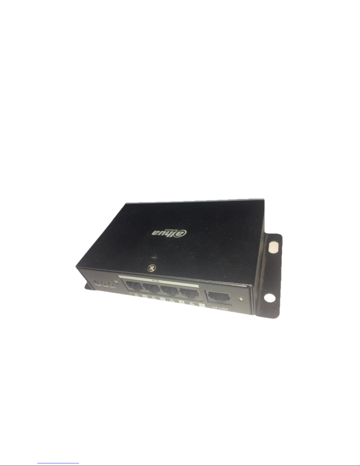
1.2 Front Panel
The front panel is shown in Figure 1-1.
Figure 1-1
SN
Mark
Name
Note
1
PWR
Power indicator light
Normally on when power is enabled
2
LINK
Network indicator light
Normally on when network port connects to LINK
3
ACT
Network indicator light
ACT flashes when data transmitting
4 4 LAN 4
IPC port
5 5 LAN 3
IPC port
6 6 LAN 2
IPC port
7 7 LAN 1
IPC port
8
UPLINK
Main network port
Device mainframe connector
1.3 Rear Panel
The rear panel is shown in Figure 1-2.
Figure 1-2
SN
Name
Note
1
Aviation port
Power supply port
Page 6

- 3 -
1.4 Aviation Port
See Figure 1-3 for more details about the aviation port.
Figure 1-3
DC 12V pin definition
Terminal Number
Definition
1
DC12V+
2
GND
3
NULL
4
NULL
Page 7

- 4 -
1.5 Installation and Connection
See Figure 1-4 for more details about the installation and connection.
Figure1-4
Note:
Network cable, camera and other accessories are not included in the accessories bag, users have to
prepare by themselves.
The network cable cover should be installed when accessing network cable, which is to prevent the
network cable from being loose during vibration.
Page 8

- 5 -
2 Quick Configuration
2.1 Software Setting
IPC needs to configure IP address which should be the same as the IP address of NVR during use.
2.1.1 Network Setting
Step 1 Enter “Main Menu”> “System Setting”> “Network Setting”interface, as shown in Figure
2-1.
Figure 2-1
Step 2
Set corresponding IP address to the '' IP Address'', ''Subnet Mask'' and ''Default gateway'', click ''Save''.
2.1.2 IPC Configuration
The IP address of IPC and the IP address of ''Network Setting'' should be kept in the same network
segment.
Page 9

- 6 -
Step 1
Enter “Main Menu”> “Remote Device”or “Main Menu”> “IPC”configuration interface, as shown
in Figure 2-2:
Figure 2-2
Step 2
Click ''Device Search'' and corresponding IPC can be searched. Attention: It will fail to search
corresponding IPC if the IP address of IPC and the IP address of NVR are not in the same network
segment.
Step 3
Click the icon under ''Edit'', enter ''Modify IP'' configuration interface, as shown in Figure 2-3:
Page 10

- 7 -
Figure 2-3
Step 4
Click ''Confirm'' after configuring corresponding IP address, the IP address of IPC is successfully
saved. Attention: NVR products from some manufacturers may not support modifying device IP
online if the “ ”in front of “Onvif” displays gray. It needs to login the WEB interface of IPC to
modify IP address via PC under this circumstance, refer to IPC operation manual for more details.
Step 5
Click ''Add'' to add corresponding IPC into the NVR device channel, check if it is well connected via
the icon color of ''Connection Status''. It means successful connection for the system when the color
of the circle turns from red to green.
Note:
Differences may exist to the configuration interface for different NVR devices.
It will fail to search corresponding IPC if the IP address of IPC and the IP address of NVR are not in
the same network segment.
Page 11

- 8 -
2.2 WEB Setting
Users can configure the IP address of IPC and the IP address of NVR via WEB.
2.2.1 Network Setting
Select ''System Setting > Network Setting'', the system enter ''Network Setting'' interface, and users can
set IP address of NVR on this interface.
2.2.2 IPC Configuration
Select ''System Setting > Advanced Options > Remote Device'', system enter ''Remote Device Setting''
interface, and users can set IP address of IPC.
Auto Registration
Select ‘’Extended Configuration > Auto Registration’’, the system enters “Auto Registration” interface.
Then it can configure “Server IP”, “Port Number” and other parameters, after the device is registered to
the server, it can visit the device after the successful connection between client and server.
 Loading...