

Page 1
FEBRUARY 2017
ITC237-PU1A-IRHL
Quick Install Guide
Official UK distribution partner
tel: +44 (0)1457 874 999 | fax: +44 (0)1457 829 201 | email: sales@cop-eu.com | web: www.cop-eu.com
Page 2
INSTALLATION OVERVIEW
ANPR Setup
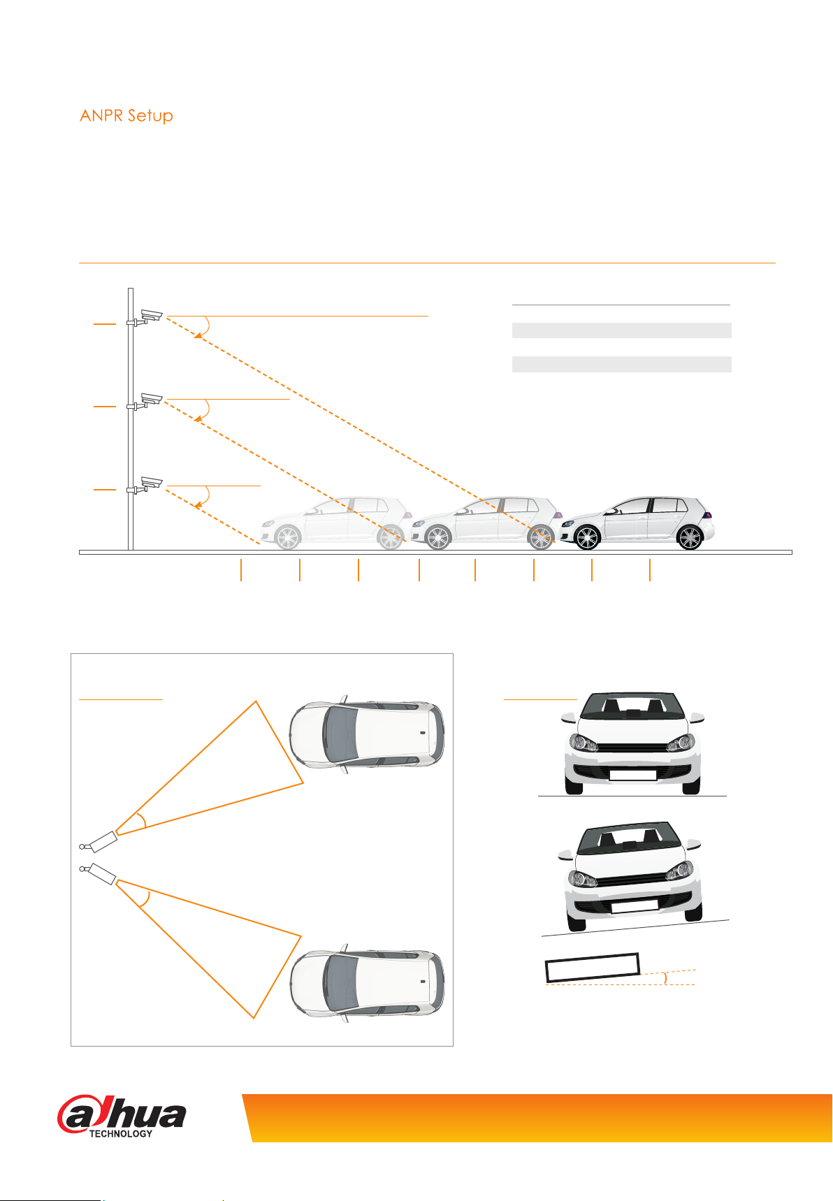
When installing the ITC237-PU1A-IRHL it is important to consider both the mounting height and angle of the camera. If the camera
is mounted too high or the horizontal/vertical angle too great, then the accuracy of the recognition software will be diminished.
Listed below are the recommended mounting height and angles for reference.
Setting Height & Distance
Capture Distance Mounting Height
6
4
Metres
30° Tilt
(Max)
30° Tilt
(Max)
6-10 metres 2 metres
10-14 metres 3 metres
14-18 metres 4 metres
18-24 metres 5 metres
24-40 metres 6 metres
2
Setting Angles
Max Angles
30°
30°
30° Tilt
(Max)
5
The horizontal angle should not exceed
30 degrees.
10 15 20 25 30
35 40
Metres
Plate Angles
AB66 CDE
AB66 CDE
AB66 CDE
The angle of the number plate should not
exceed 5 degrees (clock or anti clockwise).
Product specification is subject to change without notice. E&OE.
5°
Page 3
Installation Scenarios
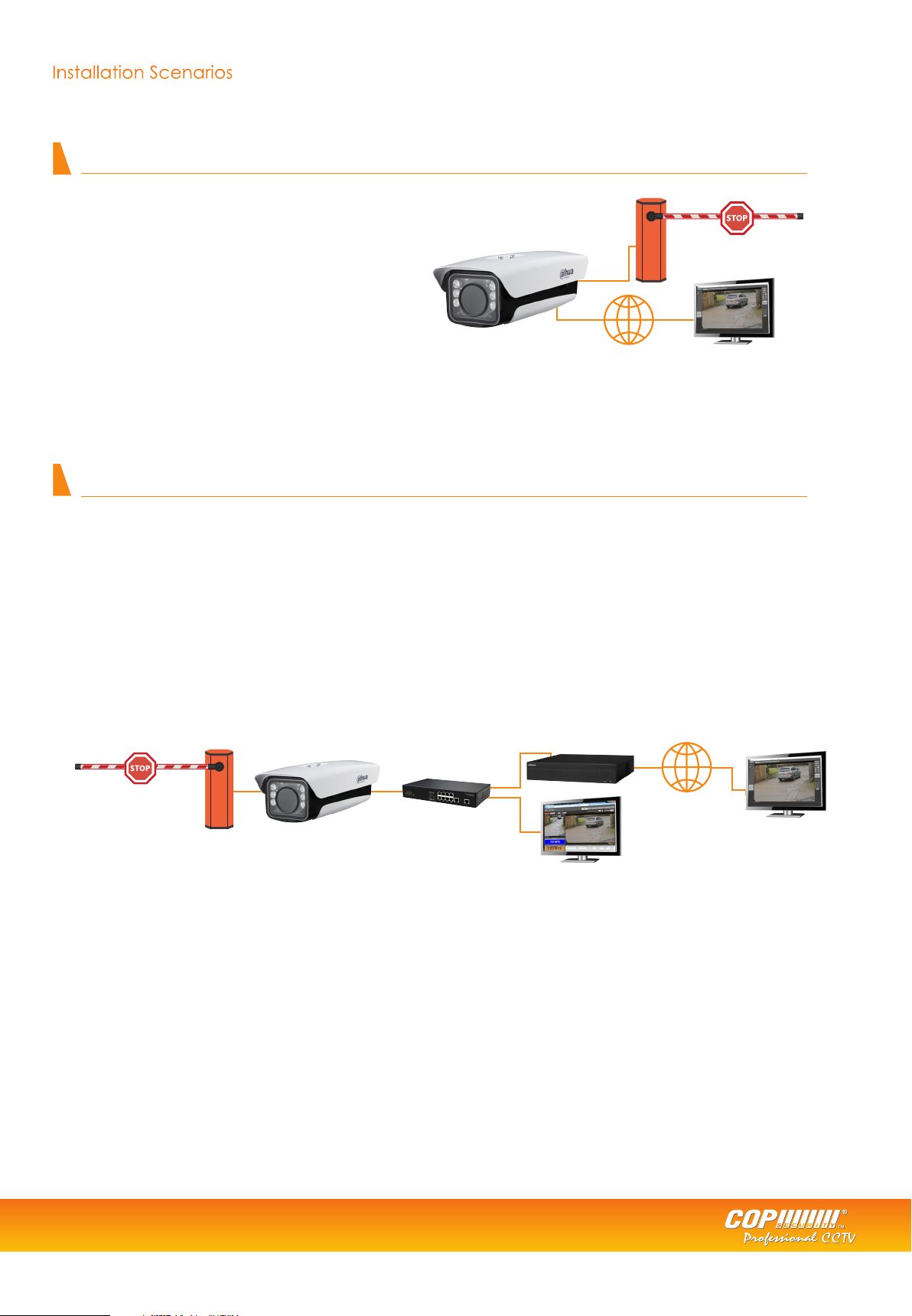
Example 1 - Standalone ANPR camera
Camera connected to network, accessed for viewing on PC using camera IP address.
Features available (with SD card installed)
• Display plate snapshot
• Building of white list
• Live View
• Alarm output
The camera can capture and store number plate snapshot images on an SD card.
No video footage will be recorded using this setup.
Network
Example 2 - Networked ANPR camera
Camera connected to NVR, accessed for viewing on NVR OR PC using camera IP address.
Features available when connected to standard recorders;
• Display plate snapshot (camera web browser)
• Building of white list (camera web browser)
• Alarm output(camera web browser)
• Live View (camera web browser)
• Continuous video recording (NVR feature)
ANPR Camera
NVR features available when connected to NVR608/NVR616 recorders;
Any plate/whitelist/blacklist trigger events which include;
• Recording • NVR relay output
• NVR buzzer • Email
• Full screen display • Snapshot
• PTZ activation
NVR
PC/Web Browser
Network
PC/Web Browser
Barrier controlled by
relay out
Switch
PC for
programming/monitoring
Tel: +44 (0)1457 874 999 | Fax: +44 (0)1457 829 201 | Email: sales@cop-eu.com | Online: www.cop-eu.com
3
Page 4
INSTALLATION
When configuring the ANPR camera for use with an NVR or as a standalone system, all devices should first be connected together.
The ITC237-PU1A-IRHL supports POE (802.3at) or can be powered by 12v DC
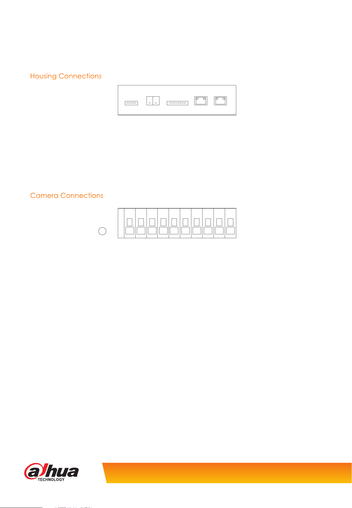
Housing Connections
LED_DRI
12v Used when not utilizing the PoE capability, connect the 12v positive to this terminal
GND This is the terminal used for the negative connection when using 12v power
LAN Connection to Network switch or NVR PoE port
POE PoE connection to body camera
12V GND HEATER LAN POE
Camera Connections
G
RESET
Reset Push button used to restore camera to factory settings
G Ground connection for alarm inputs
L1/L2 Alarm Inputs 1 & 2, used to trigger snapshot independently
NO Normally Open alarm output connection, used to trigger external devices such as barriers
C Common terminal to be used with NO terminal
ARX I1 NOTX NAB I2 C
Product specification is subject to change without notice. E&OE.
Page 5

CONFIGURATION
Once the camera has been mounted and all connections terminated, use a PC or Laptop connected to the same network switch
as the ANPR to login to the web browser interface. By default the IP address of the camera is 192.168.1.108, if required this can be
changed via the Config Tool or within the camera web browser.
Login to the camera via the computers web browser. Username: admin Password: admin123
NOTE: When connecting to an NVR it is vital to use the correct login credentials in the NVR remote device menu. Failure to input the
correct credentials will lock the camera until the correct credentials are used and the camera is rebooted.
Install
Live View
Logged Plate
Number
Plate
Snapshot
Once logged into the camera the live display will be shown.
To configure the camera lens and recognition settings, first select the install button.
The camera has built in electric back focus, this allows for adjustments to the focus to be made via the web browser (manual focus
is still required initially). To use this feature select the AutoFocus button.
Full Screen
Snapshot
Event List
Select the Region button and then Redraw, use the left mouse button to draw the detection area that vehicles will pass through.
Tel: +44 (0)1457 874 999 | Fax: +44 (0)1457 829 201 | Email: sales@cop-eu.com | Online: www.cop-eu.com
5
Page 6

CONFIGURATION
Select the Detect Line button and then Redraw, use the left mouse button to draw the detect line. The detect line is used to set
the trigger point for recognition.
Set Local Plate to the desired group, EU is the recommended setting.
Select Save to store the settings.
Go to Setup > ITC > Intelligent
The Confidence Filter sets the sensitivity for detection. If this is set to high events may be missed, if set too low then false events may
occur. The recommended setting is 70.
Once the Confidence Filter has been set, click Save to store the setting.
Go to Setup > ITC > Snap Cutout
Select the SnapCutoutEnable box and click Save to store the setting.
Product specification is subject to change without notice. E&OE.
Page 7

Go to Setup > Storage > Destination
Select the Format button to format the SD Card, once complete the SD Card is ready for use.
Return to the Live tab and select the Receive Pictures tickbox.
When vehicles pass through the detect zone, the snapshot and number plate information should be displayed. The snapshot can
be quickly downloaded by double clicking the event entry in the event list.
The Receive Pictures tickbox is only used when monitoring events via the web interface. When used with an NVR608/616 or as an
unmonitored standalone system, the tickbox is not required to be selected.
Tel: +44 (0)1457 874 999 | Fax: +44 (0)1457 829 201 | Email: sales@cop-eu.com | Online: www.cop-eu.com
7
Page 8

WHITELIST SETUP
To configure a whitelist to trigger the camera alarm output when a pre-configured number plate is detected follow the steps
below.
Go to Setup > ITC > BW List
Select the Enable tickbox
Select the Start Match tickbox
Select the White List Search tab
Click add to input a number plate into the whitelist database
Plate Number Vehicle number plate information. This must be entered in capital letters
Start Time The date this number plate should first be enabled in the whitelist
End Time The date this number plate should be disabled in the whitelist.
Master of Car Vehicle owners name
Gate mode Select whether the vehicle should be allowed access
Click OK to add the vehicle information to the whitelist.
Product specification is subject to change without notice. E&OE.
Page 9

Select the Link Sign Out tab, this option sets when the alarm output will trigger and also the time the alarm output triggers for.
Select the Enable tickbox to enable the alarm output
There are three operating modes:
Traffic Trust List Trigger the alarm output based on white list
All Snap Car Trigger the alarm output for all vehicles
Order Trigger the alarm output using computer software (This feature is currently unavailable)
When testing the alarm output the Hand On button can be used. Selecting this button will trigger the alarm output so control of external
devices can be tested.
IR LED ADJUSTMENT
The built-in IR LEDs of the camera can be configured to adjust the intensity of the IR Light.
Go to Setup > ITC > Extra Device > Light(485) Config
Work Mode Used to set the IR working mode manually or automatic, the recommended setting is Auto
Light Brightness The intensity of the IR lights
Light Arr Mask Select which array of LEDs are used. There are six LEDs grouped in pairs, each tickbox represents
and array. The default setting is all arrays selected.
Auto Mode Set whether the IRs should turn on/off based on LUX level or by a timed schedule.
Prevalue The level the LEDs should turn on/off at based on LUX. (Only applicable when Auto Mode is set
to Brightness).
Select Save to store the settings.
Tel: +44 (0)1457 874 999 | Fax: +44 (0)1457 829 201 | Email: sales@cop-eu.com | Online: www.cop-eu.com
9
Page 10

Page 11

Page 12

Cop Security | Delph New Road, Dobcross, Oldham OL3 5BG
 Loading...