

Page 1

Dahua HD Mobile Network Camera Quick Start Guide
Dahua HD Mobile Network Camera Quick Start Guide
Version 1.0.0
ZHEJIANG DAHUA VISION TECHNOLOGY CO., LTD.
Page 2

Dahua HD Mobile Network Camera Quick Start Guide
i
Welcome
Thank you for purchasing our network cameras.
This user’s manual is designed to be a reference tool for using your product.
Please read the following safeguards and warnings carefully before you use this series product.
Please keep this user’s manual well for future reference.
Important Safeguards and Warnings
Electrical safety
All installation and operation should conform to your local electrical safety codes.
The power source shall conform to the requirement of the Safety Extra Low Voltage (SELV)
standard, and supply power with voltage rated by DC 12 V or AC 24 V according to the Limited
Power Source requirement of IEC60950-1. Please note that the power supply requirement is
subject to the device label.
Make sure the power supply is correct before operating the device.
A readily accessible disconnect device shall be incorporated in the building installation wiring
Prevent the power cable from being trampled or pressed, especially the plug, power socket and the
junction extruded from the device.
We assume no liability or responsibility for all the fires or electrical shock caused by improper
handling or installation.
Environment
Do not aim the device at strong light to focus, such as lamp light and sun light, otherwise it might
cause over brightness or light marks, which are not the device malfunction, and affect the longevity
of Charge Coupled Device (CCD) or Complementary Metal-Oxide Semiconductor (CMOS).
Do not place the device in a damp or dusty environment, extremely hot or cold temperatures, or the
locations with strong electromagnetic radiation or unstable lighting.
Keep the camera away from water or other liquid to avoid damages to the internal components.
Keep the indoor device away from rain or damp to avoid fire or lightning.
Keep sound ventilation to avoid heat accumulation.
Transport, use and store the device within the range of allowed humidity and temperature.
Heavy stress, violent vibration or water splash are not allowed during transportation, storage and
installation.
Pack the device with standard factory packaging or the equivalent material when transporting the
device.
Operation and Daily Maintenance
Do not directly touch the heat dissipation component of the device to avoid scald.
Page 3

Dahua HD Mobile Network Camera Quick Start Guide
ii
Do not dismantle the device because there is no component that can be fixed by users themselves.
Otherwise, it might cause water leakage or bad image due to unprofessional dismantling.
Please contact after-sale service to replace desiccant when it becomes green.
It is recommended to use the device together with lightning arrester to improve lightning protection
effect.
It is recommended to get the grounding holes to be grounded to enhance the reliability of the
device.
Do not directly touch the optic component CCD or CMOS. You can use the air blower to blow away
the dust or dirt on the lens surface. Please use a dry cloth wetted by alcohol to wipe away the dust
gently if necessary.
Use the dry soft cloth to clean the device. If the dust is difficult to be removed, please wipe it away
with a clean cloth wetted slightly by the mild detergent, and then use the dry cloth to clean the
device. Do not use volatile solvents like alcohol, benzene, thinner, or strong detergent with
abrasiveness, otherwise it will damage the surface coating or reduce the working performance of
the device.
When installing or using the device, do not directly touch or wipe the surface of the dome cover
because it is an optical device. If stained with dirt, use oil-free soft brush or air blower to gently
wipe it away. If stained with grease or fingerprint, use soft cloth to gently wipe the water drop or oil
and wait till it is dry, and then use oil-free cotton cloth or lens cleaning paper soaked with alcohol or
detergent to wipe from the lens center outward till it is clean.
We are not liable for any problems caused by unauthorized modification or attempted repair.
Warnings
Please modify the default password after login to avoid being stolen.
Use the standard components provided by manufacturer and make sure the device is installed and
fixed by professional engineers.
The surface of the image sensor should not be exposed to laser beam radiation in an environment
where a laser beam device is used.
Do not provide two or more power supply sources for the device, otherwise it might damage the
device.
Disclaimer
This manual is for reference only. Please refer to the actual product for more details.
Minor differences might be found in user interface, and there might be deviation between the actual
value of some data and the value provided in the manual due to the reasons such as the real
environment is not stable. Please refer to the final explanation of the company if there is any doubt
or dispute.
All the designs and software are subject to change without prior written notice. The manual will be
regularly updated according to the product upgrade without prior announcement.
Please contact the supplier or customer service if there is any problem occurred when using the
device.
Please contact the customer service for the latest procedure and supplementary documentation.
Please visit our website or contact your local service engineer for more information.
Page 4

Dahua HD Mobile Network Camera Quick Start Guide
iii
The company is not liable for any loss caused by the operation that does not comply with the
manual.
If there is any uncertainty or controversy, please refer to our final explanation.
Regulatory Information
FCC Information
1.1 FCC conditions:
This device complies with part 15 of the FCC Rules. Operation is subject to the following two conditions:
This device may not cause harmful interference
This device must accept any interference received, including interference that may cause
undesired operation.
1.2 FCC compliance:
This equipment has been tested and found to comply with the limits for a digital device, pursuant to part
15 of the FCC Rules. These limits are designed to provide reasonable protection against harmful
interference. This equipment generate, uses and can radiate radio frequency energy and, if not installed
and used in accordance with the instruction manual, may cause harmful interference to radio
communication. However, there is no guarantee that interference will not occur in a particular
installation. If this equipment does cause harmful interference to radio or television reception, which can
be determined by turning the equipment off and on, the user is encouraged to try to correct the
interference by one or more of the following measures:
Reorient or relocate the receiving antenna.
Increase the separation between the equipment and receiver.
Connect the equipment into an outlet on a circuit different from that to which the receiver is
connected.
Consult the dealer or an experienced radio/TV technician for help.
Note
Please refer to the disk for more details, check and download the corresponding user’s manual and
tool.
Before installation, please open the package and check all the components are included.
Contact your local retailer as soon as possible if something is broken in your package.
Component list
Quantity
Network Camera Unit
1
Quick Start Guide
1
Installation Accessories Bag
1
CD
1
Page 5

Dahua HD Mobile Network Camera Quick Start Guide
iv
Table of Contents
1 Device Framework ................................................................................................................................. 1
1.1 Structure and dimension ............................................................................................................... 1
1.2 Dimension ..................................................................................................................................... 2
1.3 Alarm Setup ................................................................................................................................... 3
2 Device Installation ................................................................................................................................. 6
3 Network Configuration........................................................................................................................ 10
3.1 Modify IP Address ....................................................................................................................... 10
3.2 Login WEB Interface .................................................................................................................... 11
Page 6
Dahua HD Mobile Network Camera Quick Start Guide
1
1 Device Framework
1.1 Structure and dimension
Note
The following structure figures are for reference only. They are only used to know
the functions of structure components and cable ports.
There might be some minor differences between different devices, so please refer
to the actual products you purchased.
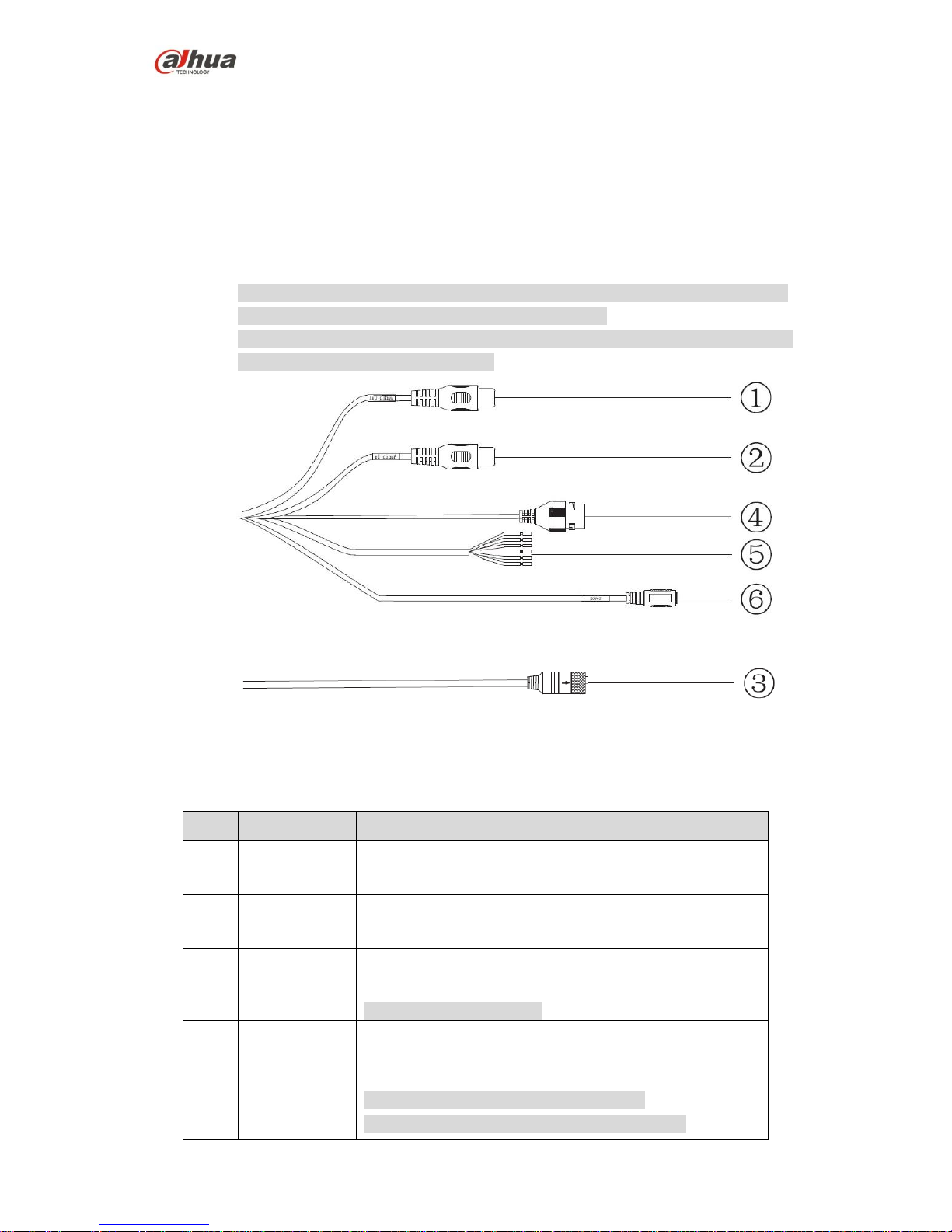
Figure 1-1
Figure 1-2
The following tables show more information about port function.
No.
Port name
Function description
1
AUDIO OUT
Output audio signal to the speakers and other
devices.
2
AUDIO IN
Input audio signal, receive analog audio signal
from pickup and other devices.
3
M12
Network port for mobile device, support PoE power
supply.
Note
Interface type is D-Coded.
4
Network port
Connect to standard Ethernet cable, provide PoE power
supply function.
Note
Some devices support two network ports.
Some devices don’t support PoE power supply.
Page 7

Dahua HD Mobile Network Camera Quick Start Guide
2
No.
Port name
Function description
5
I/O port
It includes alarm input and output. Different devices have
different I/O ports. Actual use shall be in accordance with
device label, refer to Table 1-2 for more details.
6
Power input
port
Input power, connect to DC 12V power.
Note
Power supply requirement shall be subject to device label.
Table 1-1
Port name
Cable color
Cable port name
Function description
I/O port
Blue
ALARM_IN1
Alarm input port 1, receive on-off
signal from external alarm source.
Brown
ALARM_OUT1
Alarm output port 1, output alarm
signal to alarm device.
Green
ALARM_OUT_GND1
GND 1
White
ALARM_IN2
Alarm input port 2, receive on-off
signal from external alarm source.
Red
ALARM_OUT2
Alarm output port 2, output alarm
signal to alarm device.
Black
ALARM_OUT_GND2
GND 2
Table 1-2
1.2 Dimension
Refer to Figure 1-3 and Figure 1-4 for the device dimension. The unit is mm.
Figure 1-3
Page 8

Dahua HD Mobile Network Camera Quick Start Guide
3
Figure 1-4
1.3 Alarm Setup
Note
This function is only supported by some models.
The following figure shows the Alarm setup screen.
Figure 1-5
To set up the Alarm input and output, do the following:
Step 1 Connect alarm input device to the alarm input port of I/O cable.
Step 2 Connect alarm output device to the alarm output port of I/O cable. Alarm output
is open-collector output, which needs the alarm device to pull up 10K resistance
to +3V~+5V.
Step 3 Open the WEB, and make corresponding settings for alarm input and output in
Alarm Setup. Alarm input on WEB corresponds to the Alarm input of I/O cable.
Because the alarm input device will generate high or low level signal when there
is alarm, the configurations are corresponding NO and NC inputs.
Page 9

Dahua HD Mobile Network Camera Quick Start Guide
4
Step 4 Set alarm output on the WEB, alarm output corresponds to the alarm output
port of the device, which is the alarm output port of I/O port cable.
Refer to Figure 1-6 for alarm input and output.
Figure 1-6
Alarm input: When the input signal is idle or grounded, the device can collect different
statuses of the alarm input port. When the input signal is connected to +3.3V~5V or it is
idle, the device collects the logic “1”. When the input signal is grounded, the device
collects the logic “0”.
Refer to Figure 1-7 and Figure 1-8 for alarm output.
Figure 1-7
Figure 1-8
Mode A:
Level application. The alarm outputs high and low level, and alarm output is OC. It
needs to increase pull-up resistance externally to work normally. The Max external pullup level is 5V, Max port current is 5mA. After external pull-up resistance is increased,
the output signal is high level by default (external pull-up voltage). When there is alarm
output, it switches to low level (when the working current is 5mA, output voltage is less
than 0.8V).
Page 10

Dahua HD Mobile Network Camera Quick Start Guide
5
Mode B:
Switch application. Alarm output is used to drive external circuit. The Max current is
30mA and Max voltage is 5V, and it is advised to add a relay when it is beyond the value.
Page 11

Dahua HD Mobile Network Camera Quick Start Guide
6
2 Device Installation
Note
The following figures are for reference only, please refer to the product for more
details.
Make sure the bracket installation surface can sustain at least 3X weight of the total
weight of bracket and camera.
Please cut off the power before installing Micro SD card.
Figure 2-1
Step 1 Take out the camera from the packing box, open the upper cover component.
Step 2 (Optional) Install Micro SD card, which is shown in Figure 2-2.
Note
It needs to implement this step when the device is equipped with Micro SD card
slot and it needs to use it.
Find SD sign inside the device, adjust the Micro SD card direction according to
the prompt direction shown on the device, insert it into the slot and install the
Micro SD card properly.
Page 12

Dahua HD Mobile Network Camera Quick Start Guide
7
Figure 2-2
Note
Long press the reset button for 10s with power on if it needs to restore the device
factory settings.
Step 3 Fix the device on the installation surface.
1. Take out the installation position map from the accessory bag, paste it
on the installation surface according to the monitoring area.
2. Dig 3 plastic expansion bolt bottom holes on the three hole sites with
cross sign on the installation position map, and then insert 3
expansion bolts into the mounting holes and lock them firmly.
3. Adjust the location of device installation pedestal, lead the cable into
the outlet hole on the installation surface, take out the silica gel from
the accessory bag and place it on the corresponding location of
mounting pedestal, then align the pedestal fixing holes with the three
expansion bolt fixing holes on the installation surface, tighten three
self-tapping screws into the three plastic expansion bolts and lock
them firmly, fix the pedestal on the installation surface.
Note
It needs to remove the side cable outlet slot on the upper cover
component by hand or sharp-nose pliers if the device adopts side
cable outlet.
Step 4 Adjust device monitoring direction
Loosen one screw which is located on the right of the compression cover (don’t
demount it completely), adjust the direction of lens monitoring image to proper
monitoring angle, it is recommended to use inner hex wrench to adjust, and
then tighten the screw back in place, which is shown in Figure 2-3.
Page 13

Dahua HD Mobile Network Camera Quick Start Guide
8
Figure 2-3
Note
The angle adjustment range of the lens is (-20°~0°) vertically and
(-15°~+15°) horizontally, the image rotation direction is (0°~
+360°).
Step 5 Take up the upper cover and align it with the screw hole sites on the pedestal,
put the cover back in place. Then use wrench to tighten 4 inner hex fixing
screws firmly to complete installation.
Note
Make sure the upper cover is firmly fixed to make the device waterproof.
Step 6 (Optional) Install waterproof connector for network port, which is shown in
Figure 2-4.
Note
It needs to implement this step if the device is equipped with network port
waterproof connector and it is used outdoors.
Figure 2-4
1. Keep the convex groove outward and install the rubber ring into the
network port, and keep the smaller hole of the rubber ring outward
and install the fixing rubber ring into the main body of the waterproof
connector.
2. After pulling the network cable without crystal head through main
body of waterproof connector, fixing rubber ring and waterproof
Page 14

Dahua HD Mobile Network Camera Quick Start Guide
9
fastening cover, make the crystal connector of network cable and then
insert it into the network cable.
3. Put the main body of waterproof connector on the network port and
rotate it clockwise to lock the network port and waterproof connector
firmly.
4. Put the waterproof fastening cover on the main body of waterproof
connector and rotate it clockwise to lock the waterproof connector and
waterproof fastening cover firmly.
Page 15

Dahua HD Mobile Network Camera Quick Start Guide
10
3 Network Configuration
The IP address of all the cameras is the same when leaving factory (default IP
192.168.1.108). To make the camera access to the network smoothly, please plan the
available IP segment reasonably according to the actual network environment.
3.1 Modify IP Address
The cameras which are accessed via wired network can acquire and modify the IP
address through “Quick Configuration Tool”. This section introduces the approach of
modifying IP address via “Quick Configuration Tool”. You can also modify the IP address
in the network parameters of the WEB interface. Please refer to the document WEB
Operation Manual in the disk for more details.
Note
You can search out all the cameras within the LAN via “Quick Configuration Tool”. The
camera can be configured only when the IP addresses of the camera and the computer
are in the same network segment.
To modify IP address, do the following:
Step 1 Double-click “ConfigTool.exe” to open the “Quick Configuration Tool”.
Step 2 Click to enter the interface where you can modify IP address, and then
click Search setting.
The system pops up the Setting dialog box, see Figure 3-1.
Figure 3-1
Step 3 Set the device network segment, login user name and password, and then click
OK. The system will display the searched devices after searching completes.
Step 4 Select the devices which IP addresses need to be modified, and then
click .
The system will pop up the Modify IP Address dialog box, see Figure 3-2.
Page 16

Dahua HD Mobile Network Camera Quick Start Guide
11
Figure 3-2
Step 5 Set the mode as Static, and input the planned Start IP, Subnet Mask and
Gateway.
Note
Set the mode as DHCP when there is DHCP server in the network, the device
will automatically acquire IP address from the DHCP server.
Step 6 Click OK to finish modification.
3.2 Login WEB Interface
Note
Different devices might have different WEB interfaces, the figures in this document are
just for reference, please refer to the document WEB Operation Manual in the disk and
the actual interface for more details.
To login WEB interface, do the following:
Step 1 Open IE browser and input the modified camera IP address in the address bar,
and then press Enter key.
The login interface shows, see Figure 3-3.
Figure 3-3
Step 2 Input username and password, click Login. The system will pop out WEB main
interface.
Page 17

Dahua HD Mobile Network Camera Quick Start Guide
12
Note
The default username and password is admin and admin respectively, please
modify the administrator password as soon as possible after you successfully
logged in.
Step 3 Click Here to Download Plug-in, and then install controls according to the
system prompt. See Figure 3-4 for the WEB main interface.
Figure 3-4
ZHEJIANG DAHUA VISION TECHNOLOGY CO., LTD.
Address: No.1199, Bin'an Road, Binjiang District, Hangzhou, P.R. China
Postcode: 310053
Tel: +86-571-87688883
Fax: +86-571-87688815
Email: overseas@dahuatech.com
Website: www.dahuasecurity.com
 Loading...