

Dahua IPCHDBW3300N Quick Start Manual

HD IR Vandal Proof IP Dome Camera Quick Start Guide
Version 1.0

Welcome
Thank you for purchasing our IP camera!
This quick start guide is designed to be a reference tool for your system.
Please keep this start guide well for future reference.
Please open the accessory bag to check the items one by one in accordance with the list below.
Contact your local retailer ASAP if something is missing or damaged in the bag.
Before your operation please read the following instructions carefully.
1.Electrical safety
All installation and operation here should conform to your local electrical safety codes.
The power shall conform to the requirement in the SELV (Safety Extra Low Voltage) and the Limited
power source is rated 12V DC or 24V AC in the IEC60950-1.
We assume no liability or responsibility for all the fires or electrical shock caused by improper handling
or installation.
We are not liable for any problems caused by unauthorized modification or attempted repair.
2.Transportation security
Heavy stress, violent vibration or water splash are not allowed during transportation, storage and
installation.
3.Installation
Do not apply power to the camera before completing installation.
Please install the proper power cut-off device during the installation connection.
Always follow the instruction guide the manufacturer recommended.
4.Qualified engineers needed
All the examination and repair work should be done by the qualified service engineers.
We are not liable for any problems caused by unauthorized modifications or attempted repair.
5.Environment
This series IP camera should be installed in a cool, dry place away from direct sunlight, inflammable,
explosive substances and etc.
Please keep it away from the electromagnetic radiation object and environment.
Please make sure the CCD (CMOS) component is out of the radiation of the laser beam device.
Otherwise it may result in CCD (CMOS) optical component damage.
Please keep the sound ventilation.
Do not allow the water and other liquid falling into the camera.
6. Daily Maintenance

Please shut down the device and then unplug the power cable before you begin daily maintenance
work.
Do not touch the CCD (CMOS) optic component. You can use the blower to clean the dust on the lens
surface.
Always use the dry soft cloth to clean the device. If there is too much dust, please use the water to
dilute the mild detergent first and then use it to clean the device. Finally use the dry cloth to clean the
device.
Please put the dustproof cap to protect the CCD (CMOS) component when you do not use the camera.
7. Accessories
Be sure to use all the accessories recommended by manufacturer.
Before installation, please open the package and check all the components are included.
Contact your local retailer ASAP if something is broken in your package.
Accessory Name Amount
IPC Unit
1
MD9M data converter cable
1
Accessories bag
1
Quick Start Guide
1
Warranty Card
1
Certificate Card
1
CD
1

Table of Contents
1 Framework...................................................................................................................................5
1.1 MD9M Data Converter Cable .....................................................................................5
1.2 Framework and Dimension.........................................................................................6
2 Installation ...................................................................................................................................8
2.1 Device Installation ........................................................................................................8
2.2 SD Card Installation ...................................................................................................11
2.3 Lens Adjustment.........................................................................................................12
3 Quick Configuration Tool.........................................................................................................13
3.1 Overview......................................................................................................................13
3.2 Operation .....................................................................................................................13
4 Web Operation..........................................................................................................................16
4.1 Network Connection...................................................................................................16
4.2 Login and Logout........................................................................................................16
Appendix Toxic or Hazardous Materials or Elements ...............................................................19
5
1 Framework
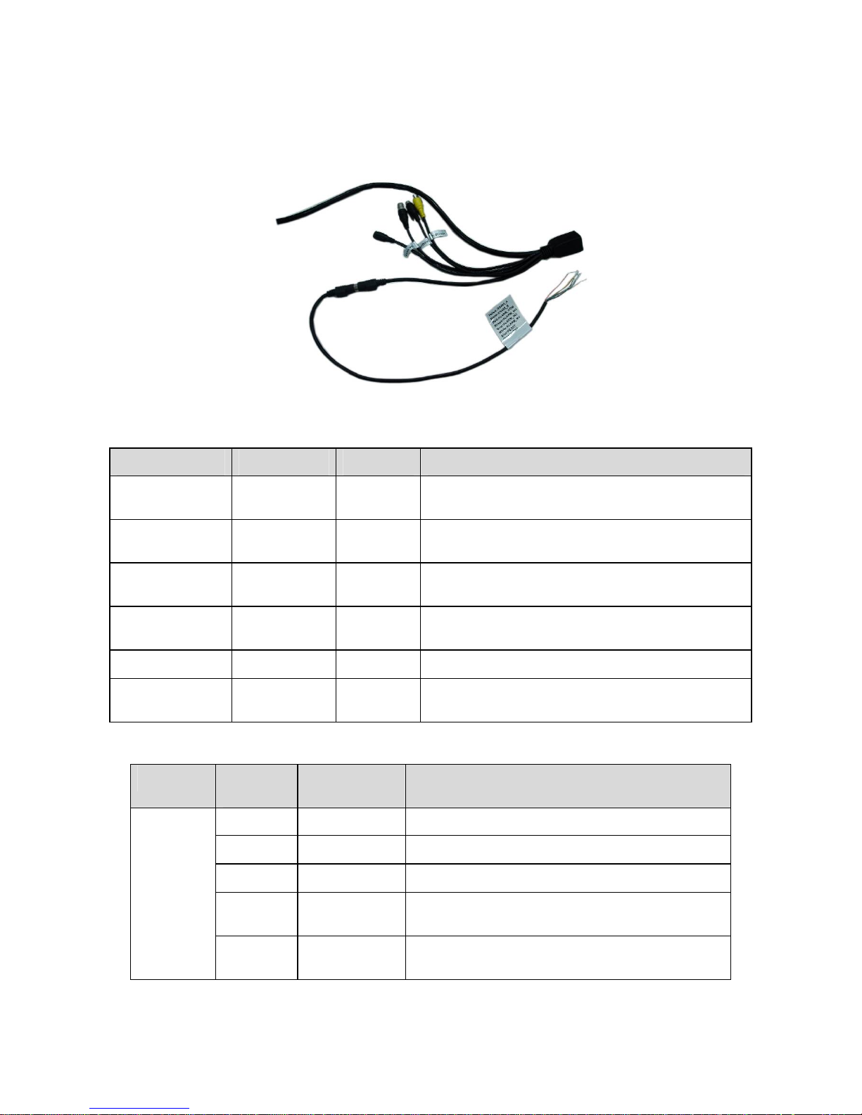
1.1 MD9M Data Converter Cable
You can refer to the following figure for MD9M data converter cable information. See Figure 1-1.
Figure 1-1
Please refer to the following sheet for detailed information.
Port Name Function Connection Note
VIDEO OUT
Video output
port
BNC
Output analog video signal. It can connect to the
TV monitor to view the video.
AUDIO IN
Audio input
port
RCA
Input audio signal. It can receive the analog audio
signal from the pickup.
AUDIO OUT
Audio output
port
RCA
Output audio signal to the devices such as the
sound box.
12V DC/AC24V
Power input
port
/ Power port. Input DC 12V/AC 24V
I/O I/O cable port / Connect to MD9M data converter cable.
LAN Network port
Ethernet
port
Connect to standard Ethernet cable.
Please refer to the follow sheet for detailed information of MD9M data converter cable.
Port Name Cable
Color
Name Note
Yellow RS485_A RS485_A port. It is to control the PTZ.
Black RS485_B RS485_B port. It is to control the PTZ.
Red ALARM_COM Alarm output public port.
Brown ALARM_IN1
Alarm input port 1. It is to receive the on-off signal
from the external alarm source.
I/O Port
Pin
Grey ALARM_IN2
Alarm input port 2. It is to receive the on-off signal
from the external alarm source.
6
Port Name Cable
Color
Name Note
White ALARM_NO
Alarm output port. It is to output the alarm signal
to the alarm device.
NO: normal open alarm output port.
It works with the ALARM_COM port.
Blue RESET
It is to restore factory default setup.
When the device is working properly, please
connect the blue cable (restore default setup port)
to the orange cable (GND signal) for 5 seconds,
the device can resume factory default setup.
Orange GND Ground port
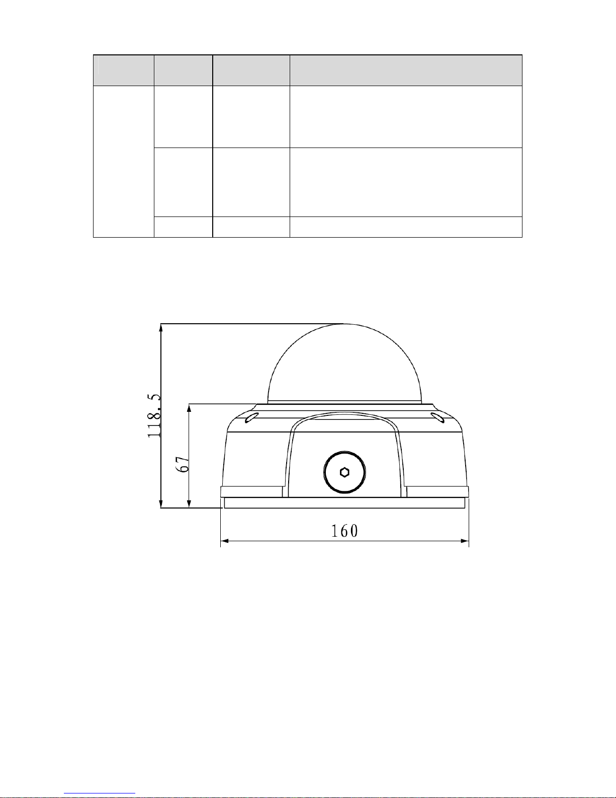
1.2 Framework and Dimension
Please refer to the following figure for dimension information. The unit is mm. See Figure 1-2 and
Figure 1-3.
Figure 1-2
 Loading...