

Dahua IPC-HDBW3300 Operation Manual

1
HD Vandal Proof IP Dome Camera
Web Operation Manual
Version 1.1

2
Table of Contents
1 Network Connection ...................................................................................................................4
2 Main Interface Introduction........................................................................................................5
2.1 Log in ..............................................................................................................................5
2.2 Monitor Channel Menu Tree .......................................................................................8
2.3 System Menu...............................................................................................................10
2.4 Monitor Window Switch..............................................................................................11
2.5 Preview Window Switch.............................................................................................11
2.6 PTZ Control..................................................................................................................11
2.7 Color and More Setup ................................................................................................14
3 Configure....................................................................................................................................16
3.1 System Information.....................................................................................................16
3.1.1 Version Information..............................................................................................16
3.1.2 HDD information...................................................................................................16
3.1.3 Log..........................................................................................................................17
3.2 System Configuration .................................................................................................18
3.2.1 General Setup ......................................................................................................18
3.2.2 Encode...................................................................................................................20
3.2.3 Schedule................................................................................................................23
3.2.4 RS232....................................................................................................................25
3.2.5 Network..................................................................................................................27
3.2.6 Alarm......................................................................................................................34
3.2.7 Detect.....................................................................................................................36
3.2.8 PTZ.........................................................................................................................39
3.2.9 Default & Backup.................................................................................................40

3
3.3 Advanced .....................................................................................................................41
3.3.1 HDD Management...............................................................................................41
3.3.2 Alarm I/O...............................................................................................................42
3.3.3 Record ...................................................................................................................42
3.3.4 Account..................................................................................................................43
3.3.5 Auto Maintenance................................................................................................44
3.3.6 Snapshot ...............................................................................................................45
3.3.7 Abnormity..............................................................................................................45
3.4 Additional Function .....................................................................................................47
3.4.1 Configure...............................................................................................................47
3.4.2 Auto Register........................................................................................................49
3.4.3 Talk Encode..........................................................................................................49
4 Search.........................................................................................................................................51
5 Alarm...........................................................................................................................................54
6 About...........................................................................................................................................56
7 Log out........................................................................................................................................57
8 Appendix No-IP DDNS.............................................................................................................58

4
1 Network Connection
This series IPC product support the Web access and management via PC.
Web includes several modules: monitor channel list, record search, alarm setup, system configuration,
PTZ control, monitor window and etc.
IP camera factory default setup:
z IP address: 192.168.1.108.
z User name: admin
z Password: admin
Please follow the steps listed below for network connection.
z Make sure the IPC has connected to the network properly.
z IPC IP address and PC IP address shall be in the same network segment. IPC default IP address is
192.168.1.108. If there is router, please set the corresponding gateway and subnet mask.
z Use order ping ***.***.***.***(* IP camera address) to check connection is OK or not.

5
2 Main Interface Introduction
2.1 Log in
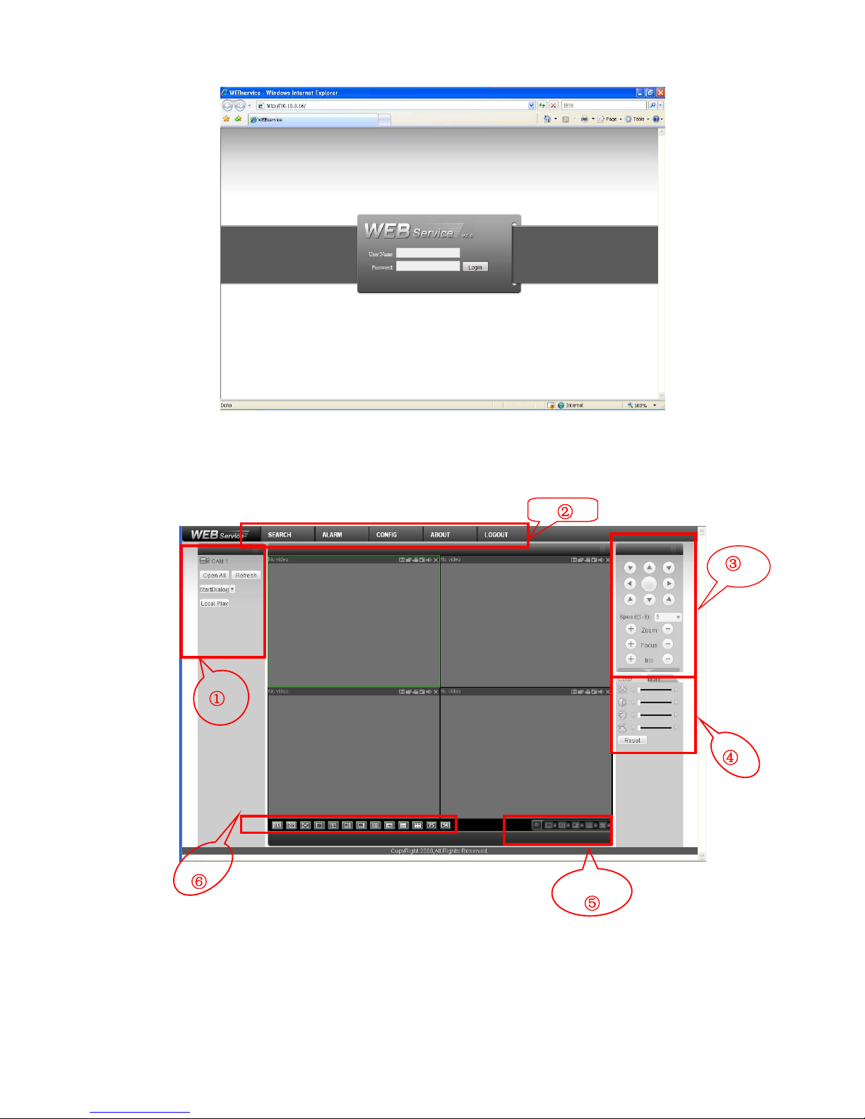
Open IE and input IPC IP address in the address column. For example, if your IP camera is
192.168.1.108, then please input http:// 192.168.1.108 in IE address column. See Figure 2-1
Figure 2-1
System pops up warning information to ask you whether install webrec.cab control or not. Please click
yes button.
If you can’t download the ActiveX file, please modify your settings as follows. See Figure 2-2.
Input your IP
address here.
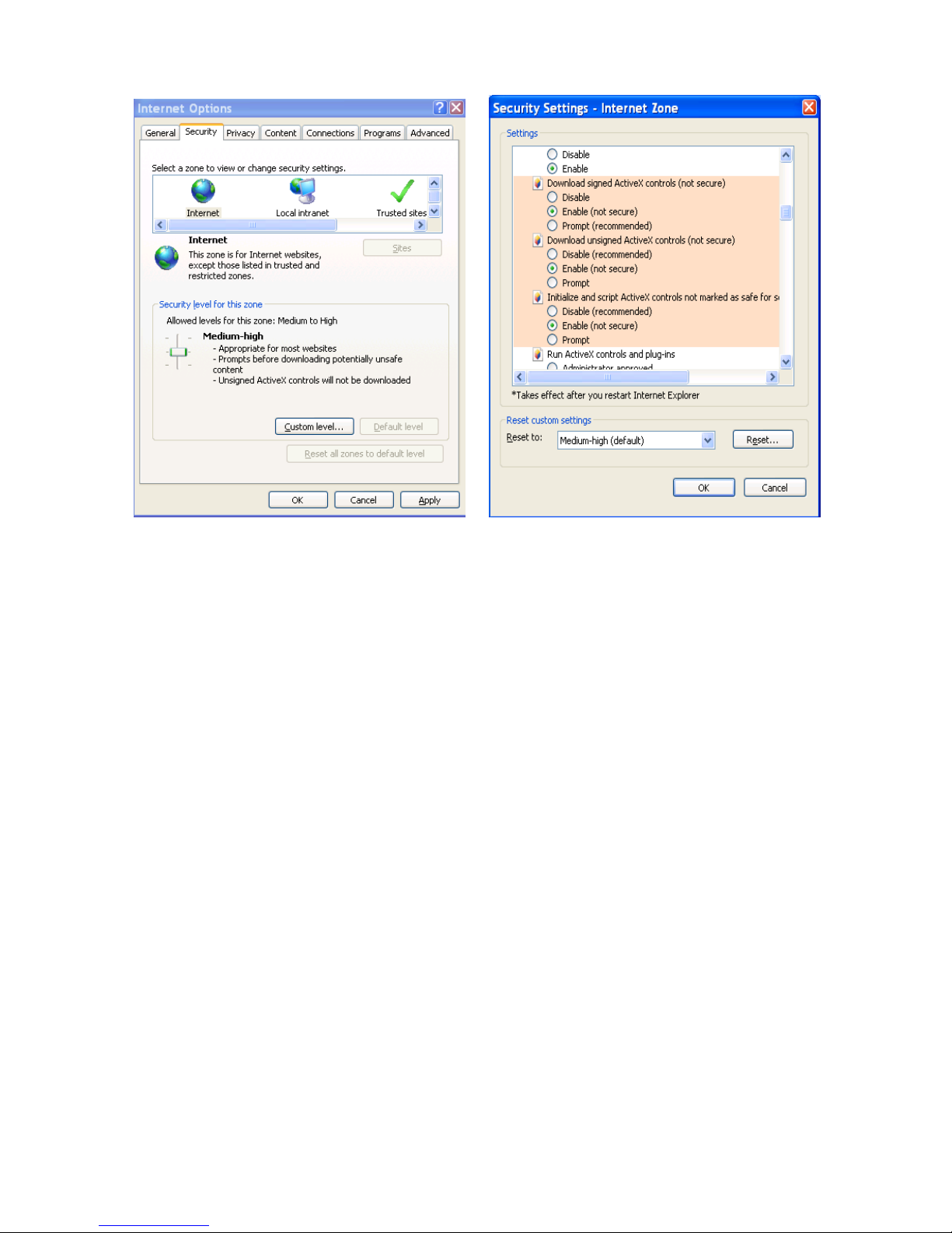
6
Figure 2-2
After installation, the interface is shown as below. See Figure 2-3.
Please input your user name and password.
Default factory name is admin and password is admin.
Note: For security reasons, please modify your password after you first login.
7
Figure 2-3
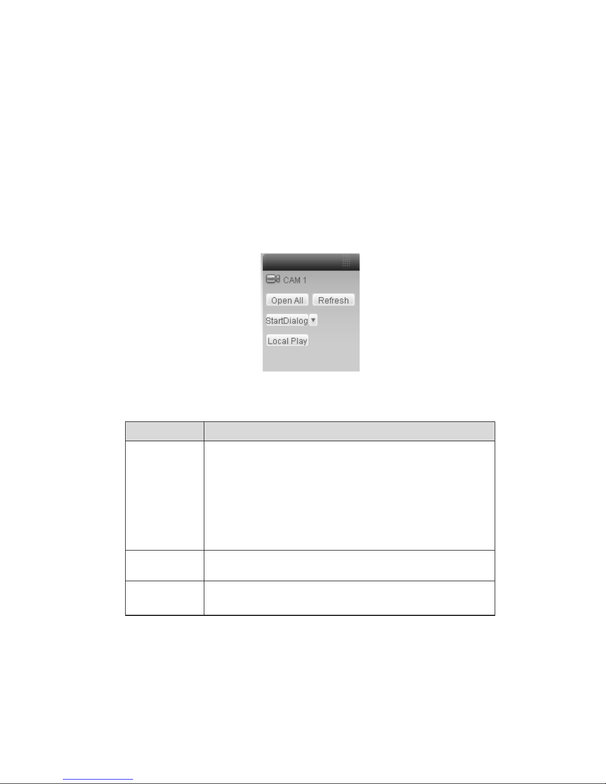
After you logged in, IPC web main interface is shown as in
Figure
2-4.
①
②
③
④
⑥
⑤
8
Figure 2-4 Web Main Interface
There are six sections:
z Section 1: Monitor channel menu tree
z Section 2: System menu
z Section 3: PTZ control
z Section 4: Video setup and other setup
z Section 5: Preview window
z Section 6: Monitor window switch
2.2 Monitor Channel Menu Tree
The monitor channel menu tree is shown as in Figure 2-5.
Figure 2-5 Monitor Channel Menu Tree
Please refer to the following sheet for detailed information.
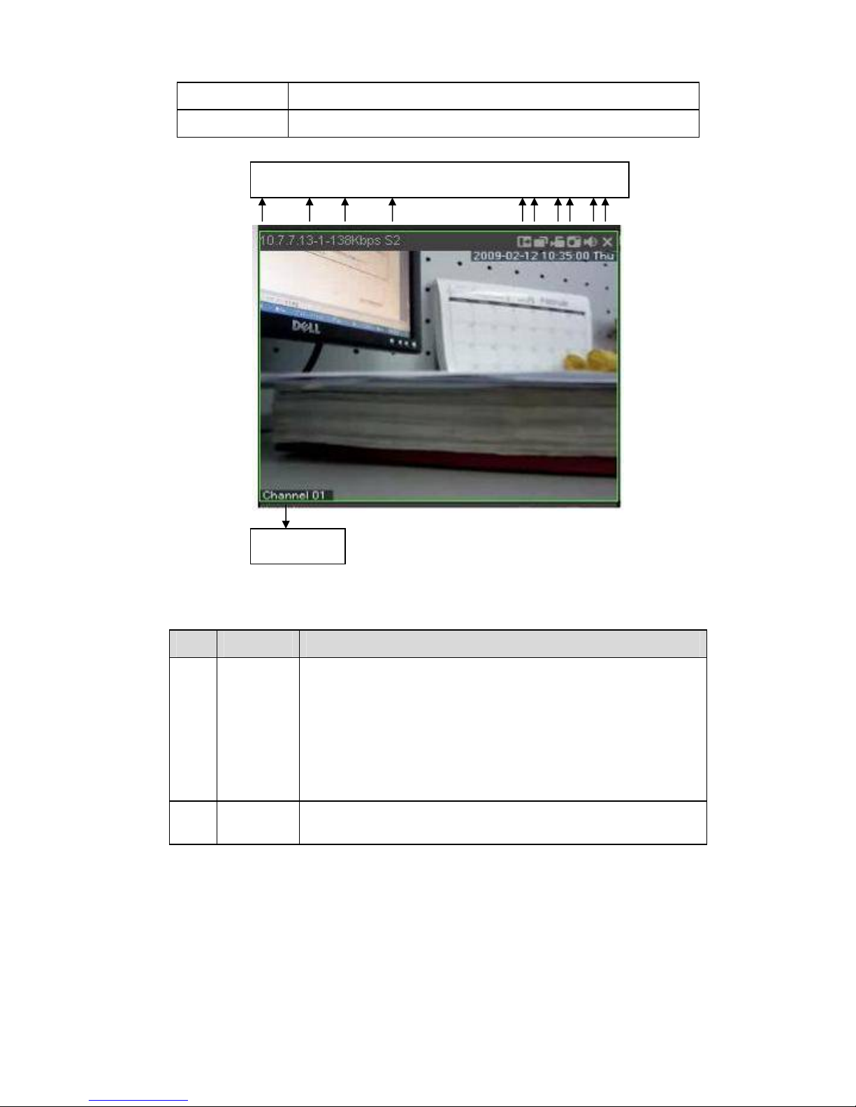
Parameter Function
Channel 1 Monitor channel 1
IPC supports main stream and extra stream.
z Main stream: In normal network width environment, main
stream can record video and audio and realize network
monitor.
z Extra stream: If network width is not sufficient, you can use
extra stream to realize network monitor.
Please note the extra stream resolution shall be less than main
stream resolution.
Open all /close
all
Click this button to open all video channels.
Once all video channels are open, it becomes close all button.
Start dialogue
You can click this button to enable audio talk.
Audio compression type: G.711a (default), PCM and etc.
The bidirectional talk allows the delay within 200ms.
9
Local play Click local play button to select file to play in PC.
Refresh Click this button to refresh monitor channel name.
Please left click one monitor to view real-time video, the monitor window is shown as in Figure 2-6.
Figure 2-6 Real-time Monitor
Please refer to the following sheet for monitor window parameter information.
SN Parameter Function
1-4 Display
device
information
z 1: IPC IP address.
z 2: Channel number.
z 3: Bit stream.
z 4: Stream decode type.
¾ S1: Overlay.
¾ S2: Off stream.
¾ S3:GD1
¾ H1: Overlay
¾ H2: off stream decoding from the display card.
5 Digital
zoom
Click this button and then left drag the mouse in the zone to
zoom in. Right click mouse system restores original status.
1 2 3 4 5 6 7 8 910
11
10
6 Change
show
mode
Resize or switch to full screen mode.
7 Local
record
When you click local record button, the system begins
recording. The recorded file is saved to system folder: \
RecordDownload(default).
You can go to chapter 2.7 to modify the local record save path.
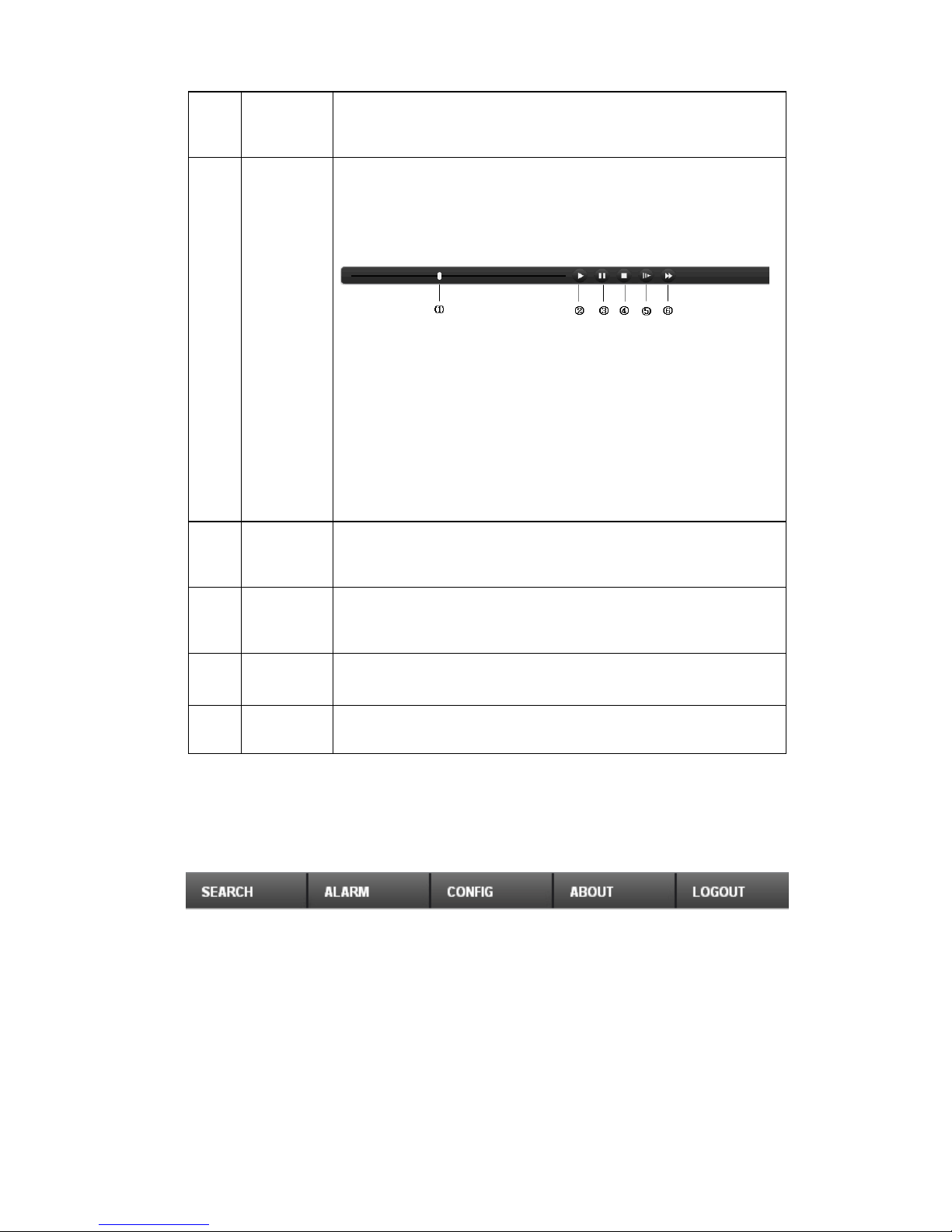
The playback bar is shown as below.
1- Playback process control
2- Play
3- Pause
4- Stop
5- Slow play
6- Fast play
Please note, once you selected window is in real-time monitor
mode, system automatically switches to playback the video by
default.
8 Capture
picture
You can snapshoot important video. All images are memorized
in system folder: \ picture download (default).
9 Audio
Turn on or off audio.(It has no relationship with system audio
setup )
10 Close
video
Close video in current window.
11 Channel
number
Current view channel number.
2.3 System Menu
System menu is shown as in Figure 2-7.
Please refer to chapter 3 Configuration, chapter 4 Search, chapter 5 Alarm, chapter 6 About, chapter 7
Log out for detailed information.
Figure 2-7 System Menu

11
2.4 Monitor Window Switch
The monitor window switch interface is shown as in Figure 2-8.
Figure 2-8 Monitor Window Switch
Here you can select 1/4/6/8/9/13/16/20/25/36-window real-time preview.
Current series IPC support 1-window and full-screen display mode.
----It is video quality adjustment button. It has relationship with decode via software.
----The original image size in the webpage.
2.5 Preview Window Switch
The preview window switch interface is shown as in Figure 2-9.
IPC series products do not support this function.
Figure 2-9 Preview Window Switch
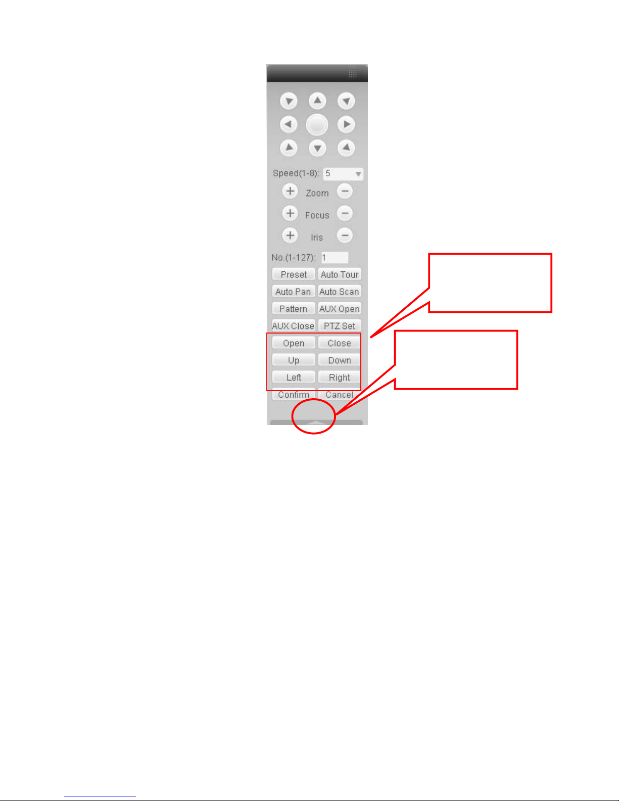
2.6 PTZ Control
Important
IPC series products do not support PTZ control function.
Before PTZ operation, please make sure you have properly set PTZ protocol. (Please refer to chapter
3.2.8 PTZ).
Here you can view direction keys, speed, zoom, focus, iris, preset, tour, pan, scan, pattern, aux close,
and PTZ setup button.
Please note: open menu/close menu/up/down/left/right/confirm/cancel buttons are for speed dome only.
z PTZ direction: PTZ supports eight directions: left/right/up/down/upper left/upper right/bottom
left/bottom right.
z Speed: The step 8 speed is faster than step 1.
12
Figure 2-10 PTZ Interface
Click PTZ set button, the interface is shown as in Figure 2-11.
You can click this icon to
display or hide the PTZ
control platform.
These six buttons are for
speed dome only.
13
Figure 2-11 PTZ Setup
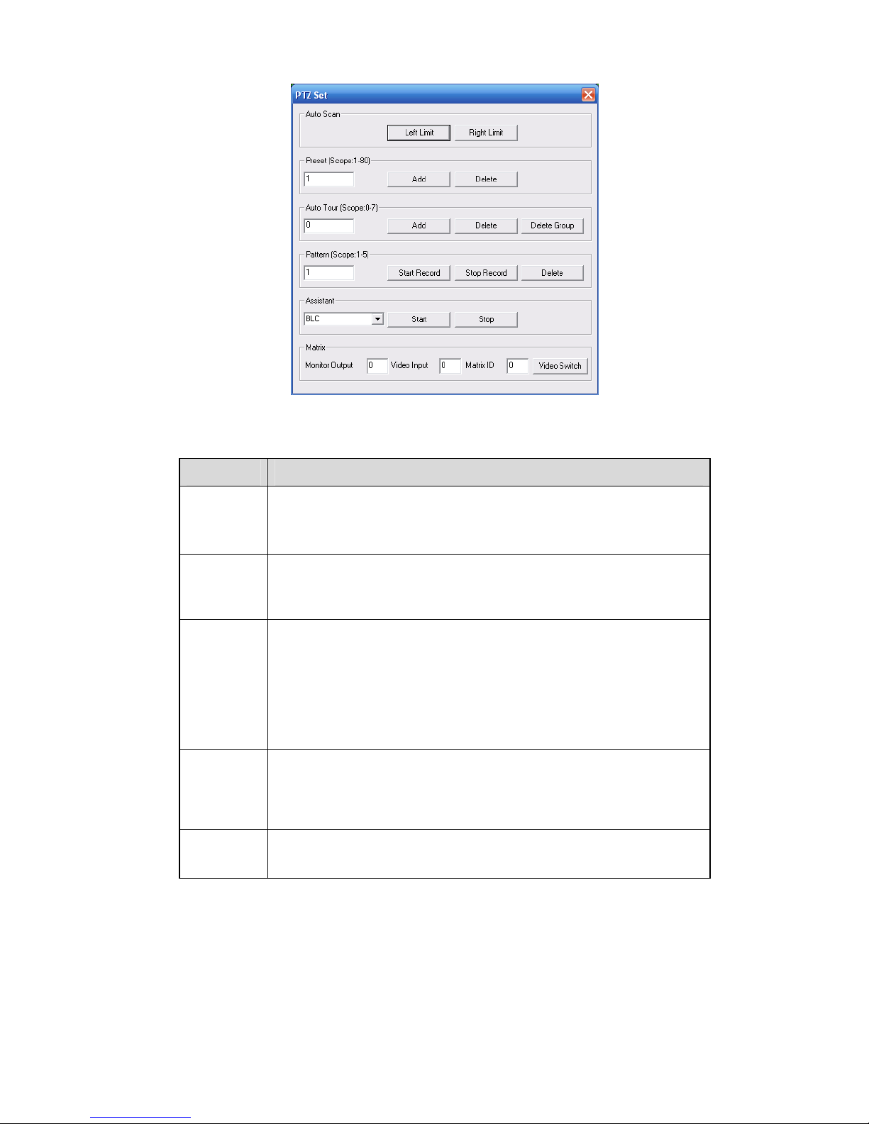
Please refer to the following sheet for PTZ setup information.
Parameter Function
Scan
z Move the camera to you desired location and then click left limit
button.
z Then move the camera again and then click right limit button to
set a right limit.
Preset
Use direction keys to move the camera to your desired location and
then input preset value. Click add button, you have set one preset.
The preset value ranges from 1 to 80. (It may vary due to different
protocols.)
Tour
z Input auto tour value and preset value. Click add button, you
have added one preset in the tour.
z Repeat the above procedures you can add more presets in one
tour.
z Or you can click delete button to remove one preset from the
tour.
The tour value ranges from 0 to 7. (It may vary due to different
protocols.)
Pattern
You can input pattern value and then click start record button to
begin PTZ movement. Please go back to Figure 2-10 to implement
camera operation. Then you can click stop record button in Figure
2-11. Now you have set one pattern.
Assistant
The assistant items include: BLC, Digital zoom, day/night mode,
camera brightness, flip.
You can select one option and then click start or stop button.
14
Parameter Function
Matrix
Please select the matrix X, and then input the corresponding monitor
output number, video input channel number, then you can click video
switch button to complete the operation.
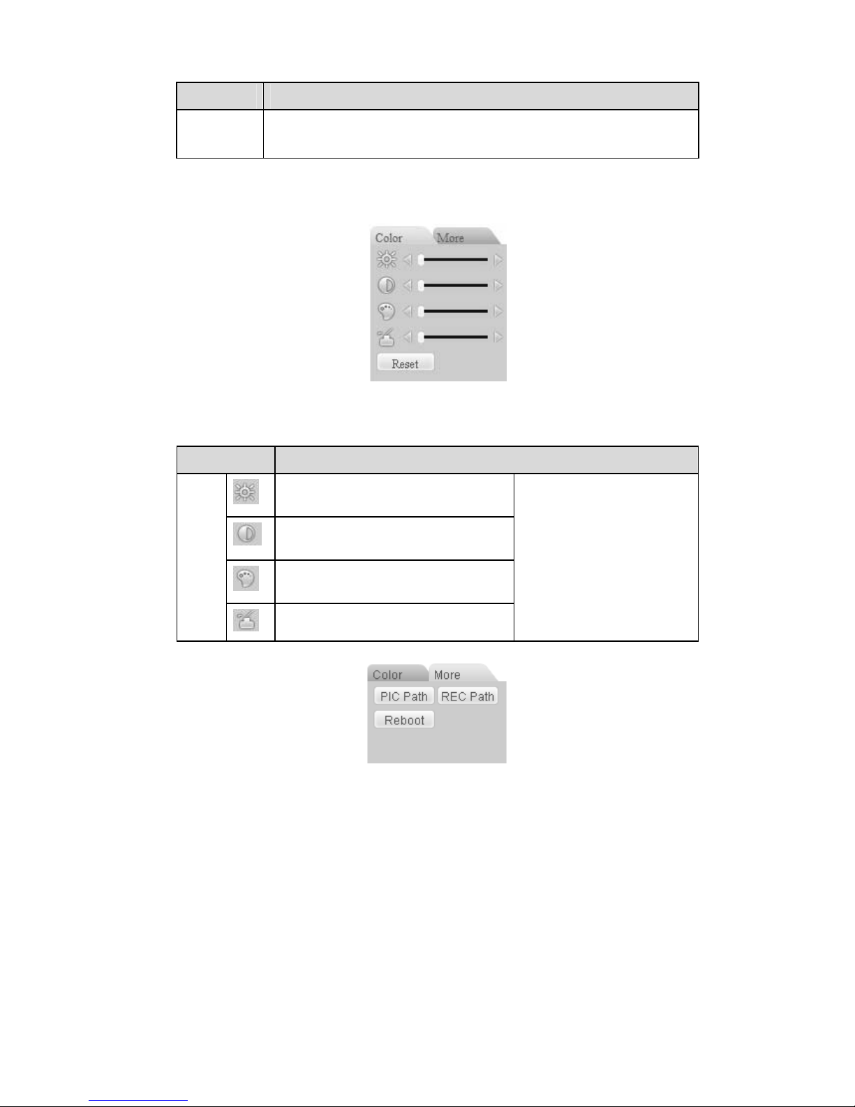
2.7 Color and More Setup
Color and other setup interface are shown as in Figure 2-12.
Figure 2-12 Color
Please refer to the following sheet for detailed information.
Parameter Function
It is to adjust monitor video
brightness.
It is to adjust monitor video contrast
ness.
It is to adjust monitor video
saturation.
Video
setup
It is to adjust monitor video hue.
Note:
z All the operations here
apply to WEB end
only.
z Please go to chapter
3.2.2 System
configuration->Encode
setup->color setting to
adjust corresponding
system items.
Click more button, the interface is shown as in Figure 2-13.
Figure 2-13 Color and More
Please refer to the following sheet for detailed information.

15
Parameter Function
Picture
Path
Click picture path button, system pops up an interface for you
to modify path.
Record
Path
Click record path button, system pops up an interface for you
to modify path.
More
Reboot Click this button, system pops up a dialogue box, please click
OK button to reboot device.
16
3 Configure
3.1 System Information
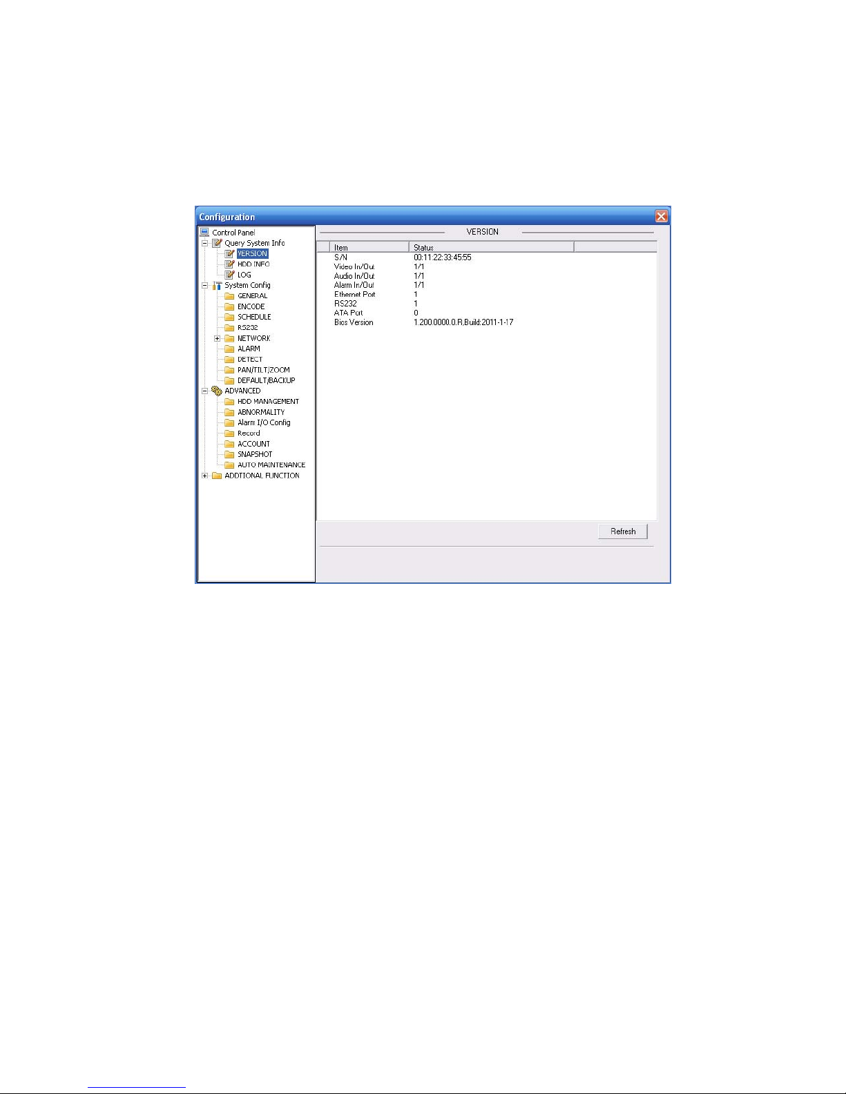
3.1.1 Version Information
Here you can view device hardware feature and software version information. See Figure 3-1.
Figure 3-1 Version Information
3.1.2 HDD information
Here you can view local storage status and network status including, free capacity and total capacity.
See Figure 3-2.
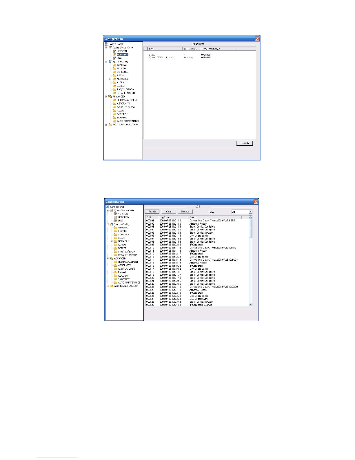
17
Figure 3-2 HDD Information
3.1.3 Log
Here you can view system log. See Figure 3-3.
Figure 3-3 Log
Click backup button, the interface is shown as in Figure 3-4.
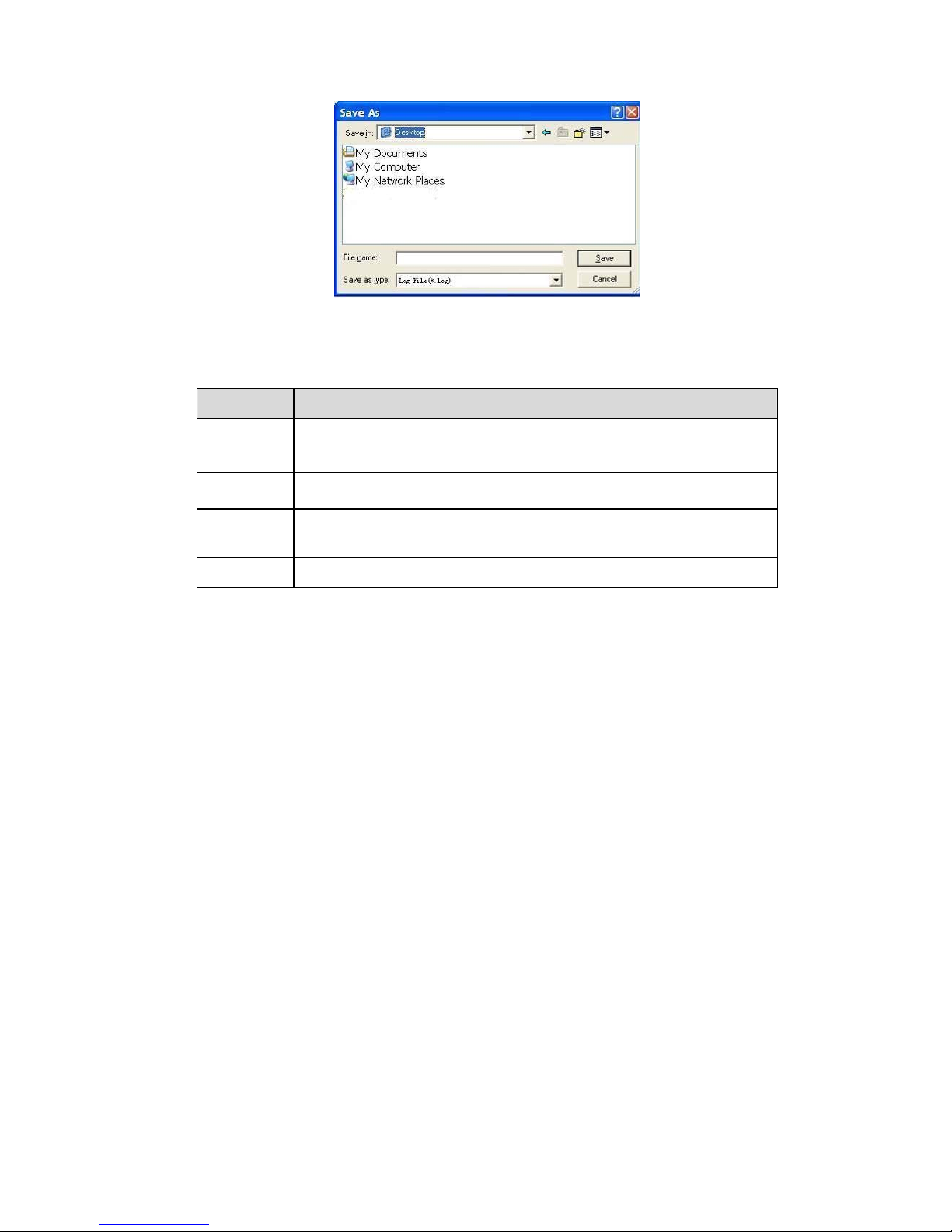
18
Figure 3-4 Save Log
Please refer to the following sheet for log parameter information.
Parameter Function
Type
Log types include: system operation, configuration operation, data
management, alarm event, record operation, user management, log
clear and file operation.
Search
You can select log type from the drop down list and then click search
button to view the list.
Clear You can click this button to delete all displayed log files. Please note
system does not support clear by type.
Backup
You can click this button to backup log files to current PC.
3.2 System Configuration
Please click save button to save your current setup.
3.2.1 General Setup
Here you can set system time, record length, video format and etc. See Figure 3-5.
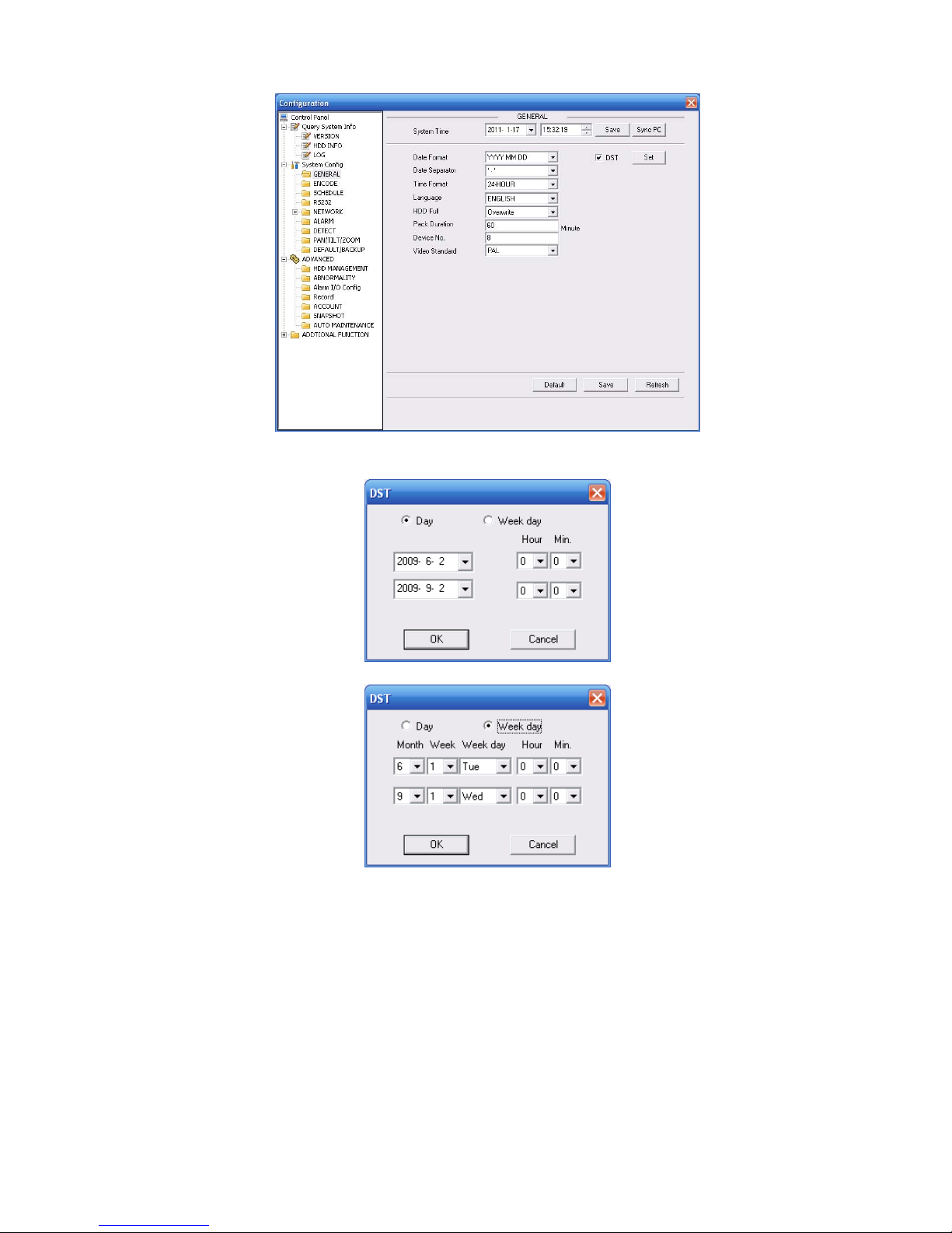
19
Figure 3-5 General Setup
Figure 3-6 DST
Figure 3-7 DST
Please refer to the following sheet for detailed information.

20
Parameter Function
System
Time
Here is for you to modify system time. Please click Save button after
your completed modification
Sync PC You can click this button to save the system time as your PC current
time.
Data
Format
Here you can select data format from the dropdown list.
Data
Separator
Please select separator such as – or /.
Time
Format
There are two options: 24-H and 12-H.
DST Here you can set day night save time begin time and end time. See
Figure 3-6 and Figure 3-7.
Language You can select the language from the dropdown list. Device needs to
reboot to get the modification activated.
HDD Full
There are two options: stop recording or overwrite the previous files
when HDD is full.
Pack
Duration
Here you can select file size. Default setup is 60 minutes.
Device No
When you are using one remote control to manage multiple devices,
you can give a serial numbers to the device.
Please note current series IPC does not support this function.
Video
Standard
This is to display video standard such as PAL.
3.2.2 Encode
Encode interface is shown as in Figure 3-8.
 Loading...