

Page 1

Mobile Network Video Recorder
User’s Manual
V 1.0.0
Page 2

i
Table of Contents
1 Features and Specifications ............................................................................................................... 1
1.1 Overview ........................................................................................................................................ 1
1.2 Function ......................................................................................................................................... 1
1.3 Features ......................................................................................................................................... 2
1.4 Specifications ................................................................................................................................ 3
2 Front Panel and Rear Panel ............................................................................................................... 7
2.1 Front Panel .................................................................................................................................... 7
2.2 Rear Panel .................................................................................................................................... 8
2.2.1 Rear Panel .............................................................................................................................. 8
2.2.2 Extension Port ........................................................................................................................ 9
2.2.3 Bidirectional talk port ............................................................................................................. 9
2.3 Remote Control .......................................................................................................................... 10
2.4 Mouse Operation ........................................................................................................................ 12
3 Installation and Connections ............................................................................................................ 14
3.1 Check Unpacked NVR ............................................................................................................... 14
3.2 About Front Panel and Rear Panel.......................................................................................... 14
3.3 HDD/SIM Card Installation ........................................................................................................ 14
3.3.1 HDD Installation ................................................................................................................... 14
3.3.2 SIM Card Installation ........................................................................................................... 16
3.4 Connecting Power Supply ......................................................................................................... 16
3.5 Connecting Audio/Video Input and Output Devices .............................................................. 16
3.5.1 Audio/Video Input Introduction .......................................................................................... 16
3.5.2 Audio/Video Output ............................................................................................................. 18
3.6 Alarm Input and Output Connection ........................................................................................ 19
3.6.1 Alarm Input and Output Details ......................................................................................... 19
3.6.2 Alarm Input Port ................................................................................................................... 20
3.6.3 Alarm Output Port ................................................................................................................ 20
4 Operation ............................................................................................................................................. 22
4.1 Boot up& Shutdown ................................................................................................................... 22
4.1.1 Preparation ........................................................................................................................... 22
4.1.2 Boot up .................................................................................................................................. 22
4.1.3 Change Password ............................................................................................................... 22
4.1.4 Reset Password ................................................................................................................... 23
4.1.5 Startup Wizard ..................................................................................................................... 24
4.1.6 General ................................................................................................................................. 26
4.1.6.1 General ........................................................................................................................ 26
4.1.6.2 Date and Time ............................................................................................................. 26
4.1.7 Network ................................................................................................................................. 27
4.1.8 Remote .................................................................................................................................. 28
4.1.9 Schedule ............................................................................................................................... 29
4.2 Preview ........................................................................................................................................ 30
4.2.1 Preview Interface ................................................................................................................. 30
4.3 Right-Click Menu ........................................................................................................................ 32
Page 3

ii
4.4 Main Menu ................................................................................................................................... 33
4.5 Remote Device ........................................................................................................................... 34
4.5.1 Remote Device .................................................................................................................... 34
4.5.2 Short-Cut Menu ................................................................................................................... 37
4.5.3 Channel Name ..................................................................................................................... 37
4.5.4 Upgrade ................................................................................................................................ 38
4.5.5 Device Status ....................................................................................................................... 39
4.5.6 Firmware ............................................................................................................................... 40
4.6 PTZ Control ................................................................................................................................. 41
4.6.1 PTZ Settings......................................................................................................................... 41
4.6.2 PTZ Control .......................................................................................................................... 42
4.6.2.1 PTZ Function Setup ................................................................................................... 44
4.6.2.2 Call PTZ Function ....................................................................................................... 46
4.7 Fisheye ........................................................................................................................................ 47
4.7.1 Fisheye de-warp during preview interface ....................................................................... 47
4.7.2 Fisheye de-warp during playback ..................................................................................... 49
4.8 Record.......................................................................................................................................... 49
4.8.1 Encode .................................................................................................................................. 49
4.8.1.1 Encode ......................................................................................................................... 50
4.8.1.2 Overlay ......................................................................................................................... 51
4.8.2 Schedule ............................................................................................................................... 51
4.8.2.1 Schedule Record ........................................................................................................ 51
4.8.2.2 Record Control ............................................................................................................ 54
4.9 Snapshot ...................................................................................................................................... 55
4.9.1 Snapshot Setup ................................................................................................................... 55
4.9.2 Schedule Snapshot ............................................................................................................. 56
4.9.3 Event Snapshot ................................................................................................................... 57
4.9.4 Enable/Disable Snapshot ................................................................................................... 59
4.10 Search & Playback ..................................................................................................................... 60
4.10.1 Search Interface .................................................................................................................. 60
4.10.2 Clip ......................................................................................................................................... 62
4.10.3 Picture Playback .................................................................................................................. 62
4.11 Event ............................................................................................................................................ 63
4.11.1 Video Detect ......................................................................................................................... 63
4.11.1.1 Video Loss ................................................................................................................... 63
4.11.1.2 Tampering .................................................................................................................... 64
4.11.2 Alarm Setup .......................................................................................................................... 65
4.11.3 Abnormality........................................................................................................................... 67
4.11.4 Alarm Output ........................................................................................................................ 68
4.12 Storage ........................................................................................................................................ 69
4.12.1 HDD Manager ...................................................................................................................... 69
4.12.2 PTZ Fn .................................................................................................................................. 70
4.12.3 PTZ Shutter .......................................................................................................................... 71
4.12.4 HDD Detection ..................................................................................................................... 72
4.12.4.1 Manual Detect ............................................................................................................. 72
4.12.4.2 Detect Report .............................................................................................................. 73
Page 4

iii
4.13 Network ........................................................................................................................................ 75
4.13.1 TCP/IP ................................................................................................................................... 75
4.13.2 Port ........................................................................................................................................ 76
4.13.3 3G/4G .................................................................................................................................... 77
4.13.4 WIFI ....................................................................................................................................... 78
4.13.5 FTP ........................................................................................................................................ 82
4.13.6 Register ................................................................................................................................. 84
4.13.7 Switch .................................................................................................................................... 85
4.14 Account Manager ....................................................................................................................... 86
4.14.1 Add User ............................................................................................................................... 86
4.14.2 Modify user ........................................................................................................................... 88
4.14.3 Change Password ............................................................................................................... 89
4.14.4 Add/Modify Group ............................................................................................................... 89
4.14.5 Security Question ................................................................................................................ 91
4.14.6 ONVIF User .......................................................................................................................... 92
4.15 System Setup .............................................................................................................................. 94
4.15.1 General ................................................................................................................................. 94
4.15.2 Date and Time ..................................................................................................................... 95
4.15.3 Display .................................................................................................................................. 96
4.15.4 RS232 ................................................................................................................................... 97
4.15.5 Auto Maintenance ............................................................................................................... 98
4.15.6 Import/Export ........................................................................................................................ 99
4.15.7 Default ................................................................................................................................. 100
4.15.8 System Update .................................................................................................................. 101
4.15.9 Backup ................................................................................................................................ 102
4.16 System Information .................................................................................................................. 103
4.16.1 HDD Information ................................................................................................................ 103
4.16.2 Record ................................................................................................................................. 105
4.16.3 BPS ...................................................................................................................................... 106
4.16.4 Satellite ............................................................................................................................... 106
4.16.5 Device Status ..................................................................................................................... 107
4.16.6 Version ................................................................................................................................ 108
4.17 Event Alarm ............................................................................................................................... 109
4.17.1 Alarm ................................................................................................................................... 109
4.17.2 MAC ..................................................................................................................................... 110
4.17.3 Gyo ...................................................................................................................................... 111
4.18 Network Info .............................................................................................................................. 112
4.18.1 Online User......................................................................................................................... 112
4.18.2 Network Test ....................................................................................................................... 113
4.18.3 Network Load ..................................................................................................................... 114
4.19 Log Info ...................................................................................................................................... 115
4.19.1 Logout /Shutdown/Restart ................................................................................................ 116
5 WEB OPERATION ........................................................................................................................... 118
5.1 Network Connection................................................................................................................. 118
5.2 Login ........................................................................................................................................... 118
Page 5

iv
5.3 Preview ...................................................................................................................................... 120
5.3.1 Preview Interface ............................................................................................................... 120
5.3.2 Monitor Window ................................................................................................................. 121
5.3.3 Window Mode .................................................................................................................... 123
5.3.4 PTZ ...................................................................................................................................... 123
5.3.5 Local Playback ................................................................................................................... 124
5.4 Playback .................................................................................................................................... 125
5.4.1 Playback Record ............................................................................................................... 127
5.4.2 Clip and Save Record ....................................................................................................... 127
5.4.3 File List ................................................................................................................................ 127
5.5 Alarm .......................................................................................................................................... 130
5.6 Setup .......................................................................................................................................... 130
5.6.1 Image .................................................................................................................................. 130
5.6.1.1 Remote Device ......................................................................................................... 130
5.6.1.1.1 Remote Device .......................................................................................................... 130
5.6.1.1.2 Upgrade ..................................................................................................................... 133
5.6.1.2 Encode ....................................................................................................................... 133
5.6.1.2.1 Encode....................................................................................................................... 133
5.6.1.2.2 Snapshot .................................................................................................................... 134
5.6.1.2.3 Overlay ...................................................................................................................... 135
5.6.1.2.4 Path ........................................................................................................................... 136
5.6.1.3 Channel Name .......................................................................................................... 136
5.6.2 Network ............................................................................................................................... 137
5.6.2.1 TCP/IP ........................................................................................................................ 137
5.6.2.2 Port ............................................................................................................................. 138
5.6.2.3 WIFI ............................................................................................................................ 139
5.6.2.3.1 WIFI .......................................................................................................................... 139
5.6.2.3.2 MAC ......................................................................................................................... 140
5.6.2.3.3 No .............................................................................................................................. 141
5.6.2.4 3G/4G ......................................................................................................................... 141
5.6.2.5 FTP ............................................................................................................................. 142
5.6.2.6 Register ...................................................................................................................... 143
5.6.2.7 Switch ......................................................................................................................... 144
5.6.3 Event ................................................................................................................................... 144
5.6.3.1 Video detect .............................................................................................................. 145
5.6.3.1.1 Video loss .................................................................................................................. 145
5.6.3.1.2 Tampering ................................................................................................................. 146
5.6.3.2 Alarm .......................................................................................................................... 146
5.6.3.2.1 Local Alarm .............................................................................................................. 146
5.6.3.2.2 IPC offline Alarm ...................................................................................................... 147
5.6.3.3 Abnormality ............................................................................................................... 148
5.6.3.3.1 Alarm Out ................................................................................................................. 149
5.6.4 Storage ................................................................................................................................ 150
5.6.4.1 Schedule .................................................................................................................... 150
5.6.4.2 HDD manager ........................................................................................................... 152
5.6.4.3 Record control ........................................................................................................... 152
Page 6

v
5.6.5 System ................................................................................................................................ 153
5.6.5.1 General ...................................................................................................................... 153
5.6.5.1.1 General ...................................................................................................................... 153
5.6.5.1.2 Date and time ............................................................................................................ 154
5.6.5.2 Display ....................................................................................................................... 155
5.6.5.3 RS232 ........................................................................................................................ 156
5.6.5.4 PTZ ............................................................................................................................. 157
5.6.5.5 Account ...................................................................................................................... 158
5.6.5.5.1 User name ................................................................................................................. 158
5.6.5.5.2 Group ........................................................................................................................ 160
5.6.5.6 Auto maintain ............................................................................................................ 162
5.6.5.7 Import/Export ............................................................................................................. 162
5.6.5.8 Default ........................................................................................................................ 162
5.6.5.9 Upgrade ..................................................................................................................... 163
5.6.6 Information .......................................................................................................................... 163
5.6.6.1 Version ....................................................................................................................... 163
5.6.6.2 Log .............................................................................................................................. 164
5.6.6.3 Online User ............................................................................................................... 165
5.6.7 HDD ..................................................................................................................................... 165
5.7 Log out ....................................................................................................................................... 165
5.8 Un-install Web Control ............................................................................................................. 166
6 Digital Surveillance System ............................................................................................................ 167
7 FAQ .................................................................................................................................................... 168
8 Appendix A HDD Capacity Calculation ......................................................................................... 173
Page 7

vi
Welcome
Thank you for purchasing our mobile network video recorder!
This user’s manual is designed to be a reference tool for your system.
Please open the accessory bag to check the items one by one in accordance with the list below.
Contact your local retailer ASAP if something is missing or damaged in the bag.
Page 8

vii
Important Safeguards and Warnings
1.Electrical safety
All installation and operation here should conform to your local electrical safety codes.
The product must be grounded to reduce the risk of electric shock.
We assume no liability or responsibility for all the fires or electrical shock caused by improper
handling or installation.
2.Transportation security
Heavy stress, violent vibration or water splash are not allowed during transportation, storage and
installation.
3.Installation
Keep upwards. Handle with care.
Do not apply power to the NVR before completing installation.
Do not place objects on the NVR
4.Qualified engineers needed
All the examination and repair work should be done by the qualified service engineers.
We are not liable for any problems caused by unauthorized modifications or attempted repair.
5.Environment
The NVR should be installed in a cool, dry place away from direct sunlight, inflammable, explosive
substances and etc.
This series product shall be transported, storage and used in the specified environments.
6. Accessories
Be sure to use all the accessories recommended by manufacturer.
Before installation, please open the package and check all the components are included.
Contact your local retailer ASAP if something is broken in your package.
Before your operation please read the following instructions carefully.
Installation environment
Keep away from extreme hot places and sources;
Avoid direct sunlight;
Keep away from extreme humid places;
Avoid violent vibration;
Do not put other devices on the top of the NVR;
Be installed in well ventilated place; do not block the vent.
Accessories
Always use accessories recommend by the manufacturer.
Caution
Page 9

viii
FOR YOUR DEVICE SAFETY, PLEASE CHANGE SYSTEM DEFAULT PASSWORD AFTER
YOU FIRST LOGIN IN!
Page 10

1
1 Features and Specifications
1.1 Overview
This series mobile NVR is a high-end HD digital video surveillance management product.
It Integrates image process technology, wireless network technology, GPS technology,
structure technology and vehicle information sampling and process technology together.
Uses strong aluminum alloy case and adopts one 2.5-inch HDDs and one SD card as the
storage media. It supports built-in 3G, WIFI wireless transmission mode and GPS module
(optional).
Installed on the vehicle, it can realize local audio/video storage and vehicle information
sampling, at the same time it can transmit real-time video and vehicle information to the
remote management centre and establish real-time remote wireless surveillance
management system.
This series NVR can be widely used in many vehicle areas or mobile surveillance areas such as
long-distance passenger transport, city public transportation, public security system, road
administration, logistics vehicle.
Important
Please note, GPS, WIFI, 3G function are optional. Please make sure you purchased product
support these functions.
1.2 Function
Slight difference may be found due to different series products.
It has analog output port, VGA port. You can use monitor or displayer, video wall to realize
surveillance function.
System supports TV/VGAI output at the same time.
Storage function
Special data format to guarantee data security and can avoid vicious data modification.
Compression format
Support multiple-channel audio and video signal. An independent hardware decodes the audio
and video signal from each channel to maintain video and audio synchronization.
Backup function
Support backup operation via USB port (such as flash disk, portable HDD)
Client-end user can download the NVR file to local HDD to backup via network.
Record playback function
Support each channel real-time record independently, and at the same time it can support search,
forward play, network monitor, record search, download and etc.
Support various playback modes: slow play, fast play, backward play and frame by frame play.
Support time title overlay so that you can view event accurate occurred time
Support specified zone enlargement.
Page 11

2
Network operation
Support network remote real-time monitor, remote record search and remote PTZ control.
Alarm activation function
Several relay alarm outputs to realize alarm activation and on-site light control.
The alarm input port and output port has the protection circuit to guarantee device safety.
Communication port
RS485 port can realize peripheral device control.
RS232 port can connect to keyboard to realize central control, and can also connect to PC COM
to upgrade system and realize maintenance.
Standard Ethernet port can realize network access function.
PTZ control
Support PTZ control via netwrok .
Support various decode protocols to allow the PTZ to control the speed dome.
GPS positioning
The GSP information can activate the record function while the search function can activate the
vehicle movement track.
Please note only the unit of GPS module supports this function.
3G/WIFI network
Latest wireless network communication technology allows you to easily control the device.
Please note only the unit of 3G/WIFI module supports this function.
Removable HDD design
The professional removable anti-vibration design. It supports fix and removable operation and can
connect to PC to realize fast and convenience data backup.
Dual–stream
Considering the wireless network band is small and the network is not stable, system adopts the
dual stream to implement real-time record and network transmission independently, which greatly
optimizes the network transmission encode code and enhance the wireless network control
compatibility.
Vehicle status record
There are six external alarm ports. You can connect to the door signal, direction indicator lamp
signal, reversing light signal, brake lamp signal and etc to prompt the driver and record vehicle
status.
1.3 Features
Aluminum alloy case, small and sound ventilation, high stability.
Built-in power module, convenient installation.
Support PoE, can supply power to the network camera directly.
Abundant functions, support various alarm mode, record mode and support multiple
Page 12

3
information, vehicle status sampling and record function.
Parameter
4-channel series
System
Main
Processor
High-performance industrial embedded micro controller
OS
Embedded LINUX
System
Resources
Multiplex operations: Multiple-channel record, multiple-channel playback
and network operation simultaneously
Interface
User-friendly graphical user interface
Input
Devices
Mouse, remote control, keyboard, touch panel
Input
Method
Arabic number, English character, donation and extension Chinese
(optional)
Shortcut
Function
Copy/paste operation, USB mouse right-key shortcut menu, double click
USB mouse to switch screen.
Compression
Standard
Video
Compressio
n
H.264,H.265,dual-stream
Audio
Compressio
n
G711U、G711A、PCM
Video monitor
Video Input
4-ch network compression video input
Video
Output
1-ch VGA output.
Video
Standard
Support PAL/NTSC.
Record
Speed
Real-time Mode: PAL 1f/s to 25f/s per channel and NTSC 1f/s to 30f/s per
channel
Video
Partition
1/4 window(s)
Monitor
Touring
Support monitor tour functions such as alarm and schedule auto control.
Resolution
(PAL/NTSC)
Realtime monitor: Max 4K (depends on the network camera.)
Playback: Max 4K (depends on the network camera.)
Support dual-stream function.
Built-in 3G/4G, WIFI wireless transmission module, and GPS module.
MAC address collection and fisheye function.
Support VGA output at the same time.
Slight function differences may be found due to different series.
1.4 Specifications
Page 13

4
Image
Quality
6-level image quality (Adjustable)
Image
Information
Channel information, time information, GPS information, plate information
Fisheye
Support fisheye connection and fisheye de-warp function.
Audio
Audio Input
1-ch bidirectional talk audio input.
Audio
Output
1-ch bidirectional talk audio output.
Bidirectional
Audio
Support bidirectional talk function.
Support 1-channel active MIC input and 1-channel line out.
Hard disk
Hard Disk
One built-in 2.5-inch SATA port (Max 2TB. Support expansibility function
to 6T).
Record and
playback
Recording
Mode
Manual recording, schedule recording and alarm recording
Priority: Manual recording>alarm recording>schedule recording.
Recording
Length
1 to 120 minutes single record duration (Default setup is 60 minutes)
Playback
Repeat Way
When hard disk is full, system can overwrite previous video file.
Record
Search
Various search engines such as time, type and channel.
Playback
Mode
Various fast play, slow play speeds, manual frame by frame playback and
reverse play mode.
Various File
Switch
Ways
Can switch to previous or next file or any file in current play list.
Can switch to file on other channel of the same time. (If there is a file)
Support file continuous play, when a file is end system auto plays the next
file in the current channel
Multi-chann
el Playback
1/4-channel playback.
Window
Zoom
Switch between self-adaptive screen/full screen when playback
Partial
Enlargemen
t
When in one-window full-screen playback mode, you can select any zone
to activate partial enlargement function.
Backup
function
Backup
Mode
HDD backup
Support peripheral USB backup device. (Flash drive, portable HDD)
Support network download and save
Network
Function
Network
control
View monitor channel remotely.
NVR configuration through client-end and web browser
Upgrade via client or browser to realize remote maintenance.
View alarm information such as external alarm, motion detection and
video loss via client.
File download backup and playback
Page 14

5
Multiple devices share information via corresponding software such as
professional surveillance software (PSS)
Duplex transparent COM
Network alarm input and output
Bidirectional audio.
Auto select network
Customized network type and parameters
Display network signal intensity
Motion
Detection and
Alarm
Video Loss
Alarm can activate external alarm or screen message prompt.
Alarm responding time≤5s
External
Alarm
Support record activation function or activate external alarm or screen
message in specified period.
Manual
Alarm
Control
Enable or disable alarm input channel
Can simulate alarm signal to specific alarm output channel.
Alarm Input
6-ch alarm input(NO/NC), alarm input voltage 8-25V. 1-channel pulse
speed measurement.
Alarm
Output
2-channel relay output: One on-off signal output, one is controllable 12V
power output.
Alarm Relay
DC 30V 1A,AC 125V 0.3A (Activation output)
Interface
USB
Interface
Two USB 2.0 port (One at the front panel and one at the rear panel
extension cable)
Network
connection
RJ45 10M/100M/1000M self-adaptable Ethernet port
VGA
Support VGA output
SD Card
Slot
Insert SD card as R/W device or redundant HDD.
RS485
One RS485 port.
It is the PTZ control port
Support various PTZ control protocols.
CAN
Can provide large power to PTZ and etc.
RS232
Two port : Extension RS232 port and aviation port RS232.
Ordinary COM (Debug),keyboard connection and transparent serial
port(COM input and output via network )
Extension
Function
GPS
Built-in GPS module. Display/encode GPS information.
3G/4G
Built-in 3G/4G module (EVDO、WCDMA、TD-LTE、FDD-LT). Support dial
time setup. SMS or phone to trigger online/offline.
Intelligent
Function
MAC Info
Collect MAC address of the cell phone, PAD, device and so on in the
surrounding environments.
Gyro
Support sharp turn, turn over or collision detection.
Blacklist
Working with the platform. The platform can send out the blacklist to the
device. Device can auto upload and notify the platform once there is any
matched result.
Page 15

6
System
Information
Hard Disk
Information
Display HDD current status
Data
Stream
Statistics
Data stream statistics for each channel (in wave mode)
Log
statistics
Backup to 1024 log files.
Support various search engines such as time and type.
Version
Display version information: channel amount, alarm input and output
amount, system version and release date.
On-line user
Display current on-line user
User
Management
User
Manageme
nt
Multi-lever user management; various management modes
Integrated management for local user, serial port user and network user.
Configurable user power.
Support user /group and its corresponding rights modification.
No limit to the user or group amount.
Password
Authenticati
on
Password modification
Administrator can modify other user’s password.
Account lock strategy
Five times login failure in thirty minutes may result in account lock.
Upgrade
TFTP COM tool or network update tool.
Login, Logout and Shutdown
Password login protection to guarantee safety
User-friendly interface when login. Provide the following options: Logout
/shutdown/ restart.
Right authentication when shut down to make sure only those proper
people can turn off NVR
General
Parameter
Power
DC +6V~+36V self-adaptive, connect negative end to the ground
Power
Consumptio
n
13W (No HDD or other peripheral device.)
Standby power consumption:
Small vehicle: 12V, 0.12W
Large vehicle: 24V, 0.27W
Working
Temperatur
e
-35℃-+60℃
Working
Humidity
10%-90%
Anti-vibratio
n
Patent anti-vibration technology
Air Pressure
86kpa-106kpa
Dimension
1DIN case,front panel 190*60mm(W*H), rear panel 180*50mm(W*H),
Depth:210mm
Weight
3.0Kg (With HDD)
Installation
Mode
Desktop installation
Page 16
7
2 Front Panel and Rear Panel
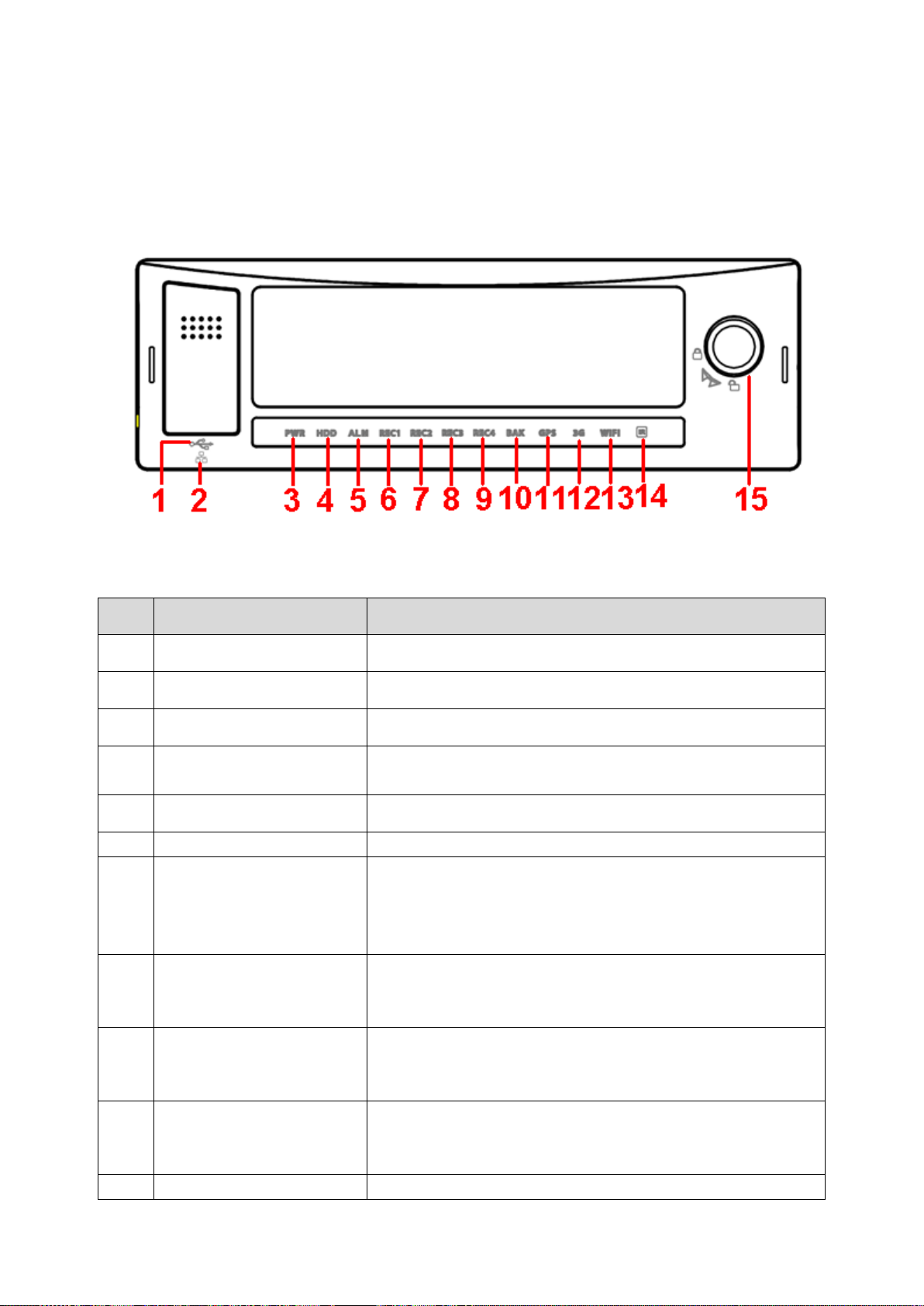
SN
Name
Port name and indicator light
1
USB port
USB port. To connect to mouse, or flash disk to backup data.
2
RJ45 network port
Network port.
3
Power indicator light
The red light is on when the device is running.
4
HDD indicator light
The blue light is on when there is HDD. The light is off when
there is no HDD.
5
Alarm indicator light
There is an alarm when the blue light is on.
6~9
Record indicator light 1~4
The blue light is on when system is recording.
10
Backup indicator light
The blue light is flashing when system is backup.
The blue light is on when the backup is finish.
The light is off when the backup error occurs or the flash
disk is removed.
11
GPS indicator light
The blue light is on when GPS function is normal.
Please note only the unit of GPS module supports this
function.
12
3G indicator light
The blue light is on when 3G function is normal.
Please note only the unit of 3G module supports this
function.
13
WIFI indicator light
The blue light is on when WIFI function is normal.
Please note only the unit of WIFI function supports this
function.
14
Remote control receiver
It is to receive the signal from the remote control.
2.1 Front Panel
The front panel is shown as in Figure 2-1.
Figure 2-1
Please refer to the following sheet for detailed information.
Page 17
8
SN
Name
Port name and indicator light
15
Door lock/unlock (Device
on/off button)
Please unlock the device before you remove the HDD
box. Otherwise system is going to shut down
automatically.
System can not boot up once the button is unlock.
Please lock the device first and the boot up the device. It
is to save the HDD.
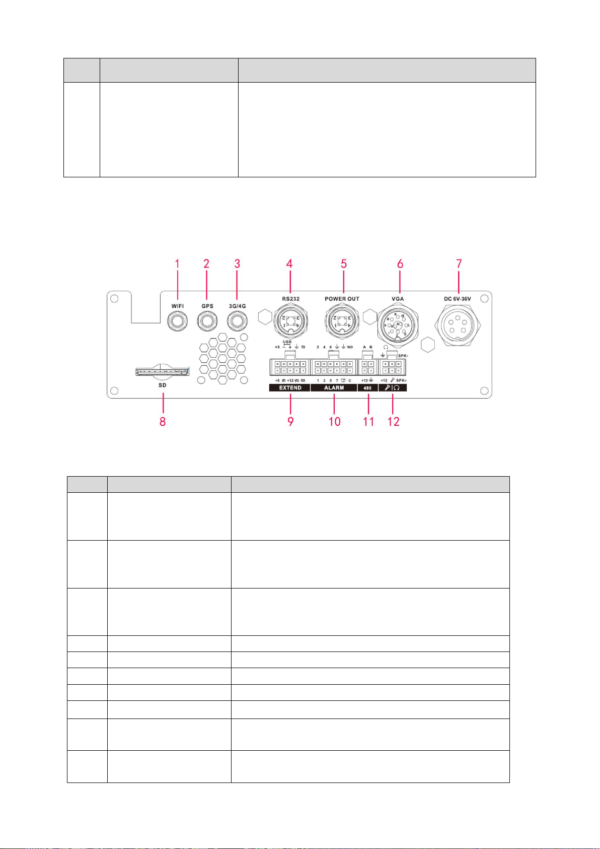
SN
Name
Function
1
WIFI antenna port
WIFI antenna port
Please note only the unit of WIFI module supports
this function.
2
GPS port
GPS port
Please note only the unit of GPS module supports
this function.
3
3G antenna port
3G antenna port
Please note only the unit of 3G module supports this
function.
4
RS232
RS232 port
5
Power out
Provide power to the outside.
6
VGA port
VGA port, including VGA all kinds of signal ports.
7
Device power input
Power input port
8
SD
SD card port
9
Extension port
Extension port. Please refer to Figure 2-3 for detailed
information.
10
Alarm input/output port
Alarm input/output port, GND port, and 12V output.
Please refer to chapter 3.6 for detailed information.
2.2 Rear Panel
2.2.1 Rear Panel
The rear panel is shown as in Figure 2-2.
Figure 2-2
Please refer to the following sheet for front panel button information.
Page 18
9
SN
Name
Function
11
RS485 and CAN BUS
port.
RS485 communication port. It can control PTZ.
Reserved port. For data exchange between vehicles
CAN network and other devices of CAN port.
12
Audio input and output
port.
Bidirectional input and output port. Please refer to Figure
2-4 for detailed information.
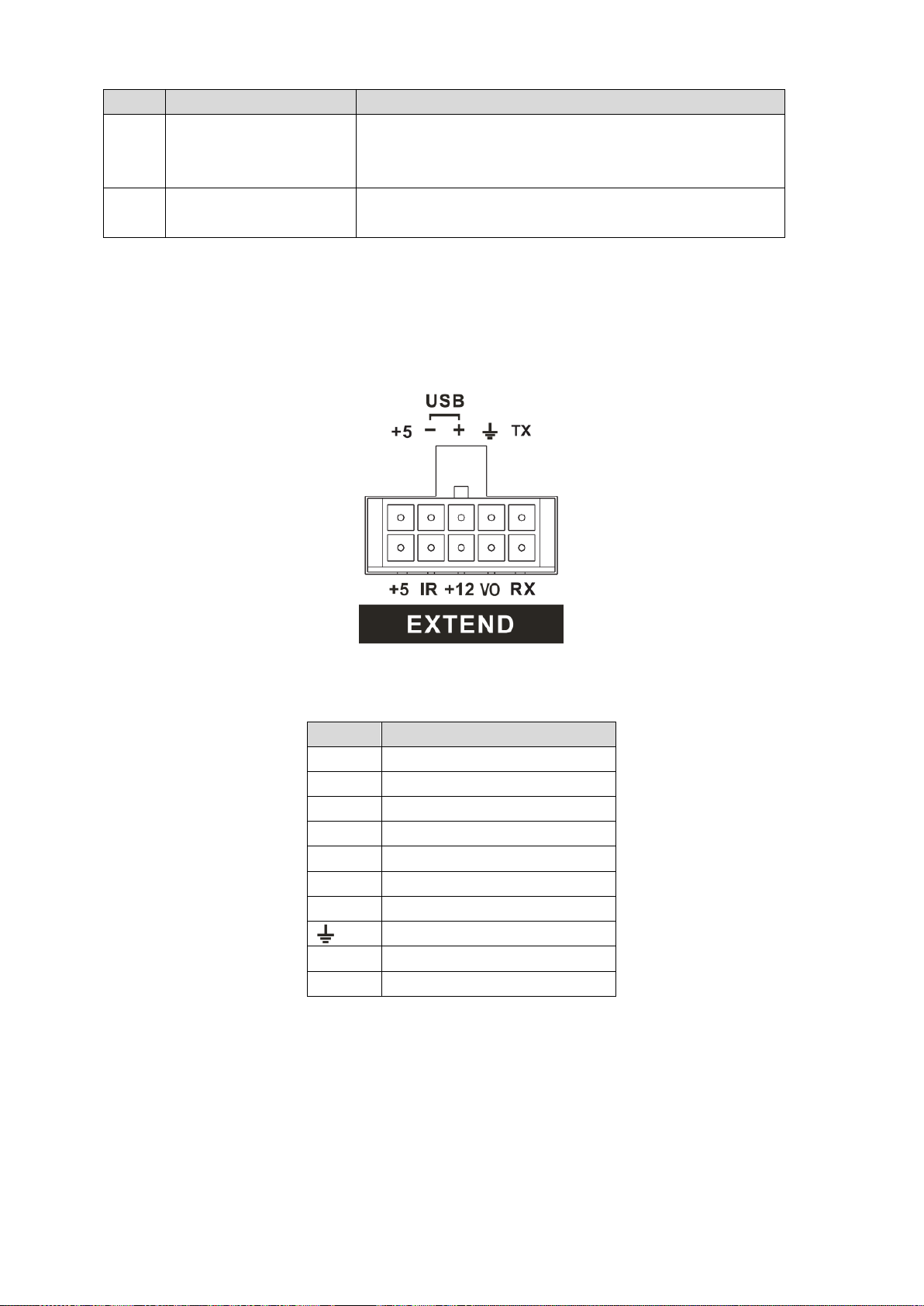
SN
Function
+5
+5V Output (Bottom line)
+5
USB 5V (Top line)
IR
IR receiver port
-
USB data
+12
+12V output
+
USB data+
VO
AV video output
GND
RX
RS232 RX
TX
RS232 TX
2.2.2 Extension Port
The following contents are to introduce function of each port. You can make connection
cable by yourself or you can contact your local retailer to purchase.
The extension port1 is shown as in Figure 2-3.
Figure 2-3
Please refer to the following sheet for detailed information.
2.2.3 Bidirectional talk port
The following contents are to introduce function of each port. You can make connection
cable by yourself or you can contact your local retailer to purchase.
The bidirectional talk port is shown as in Figure 2-4.
Page 19
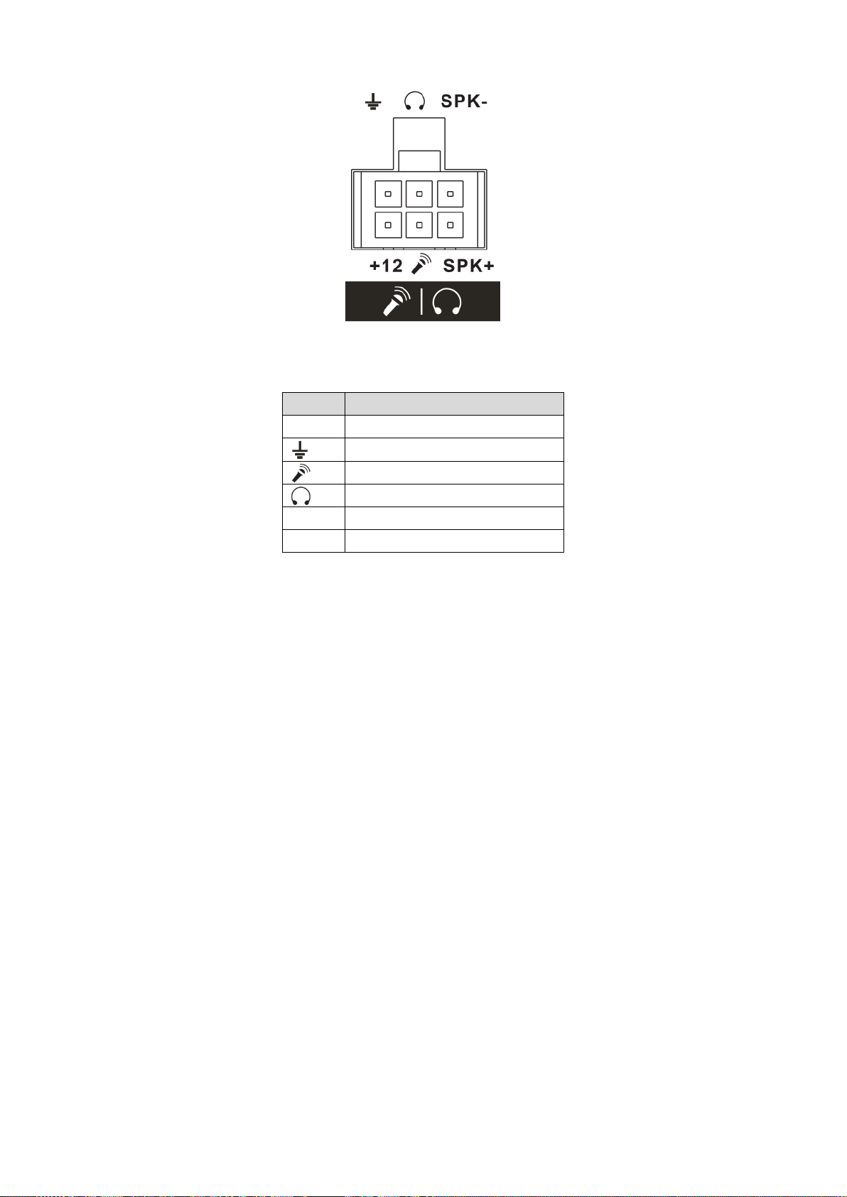
10
SN
Function
+12
+12V output
GND
Mic In. Connect to speaker.
Mic Out. Connect to earphone.
SPK+
Speak positive.
SPK-
Speak negative.
Figure 2-4
Please refer to the following sheet for detailed information.
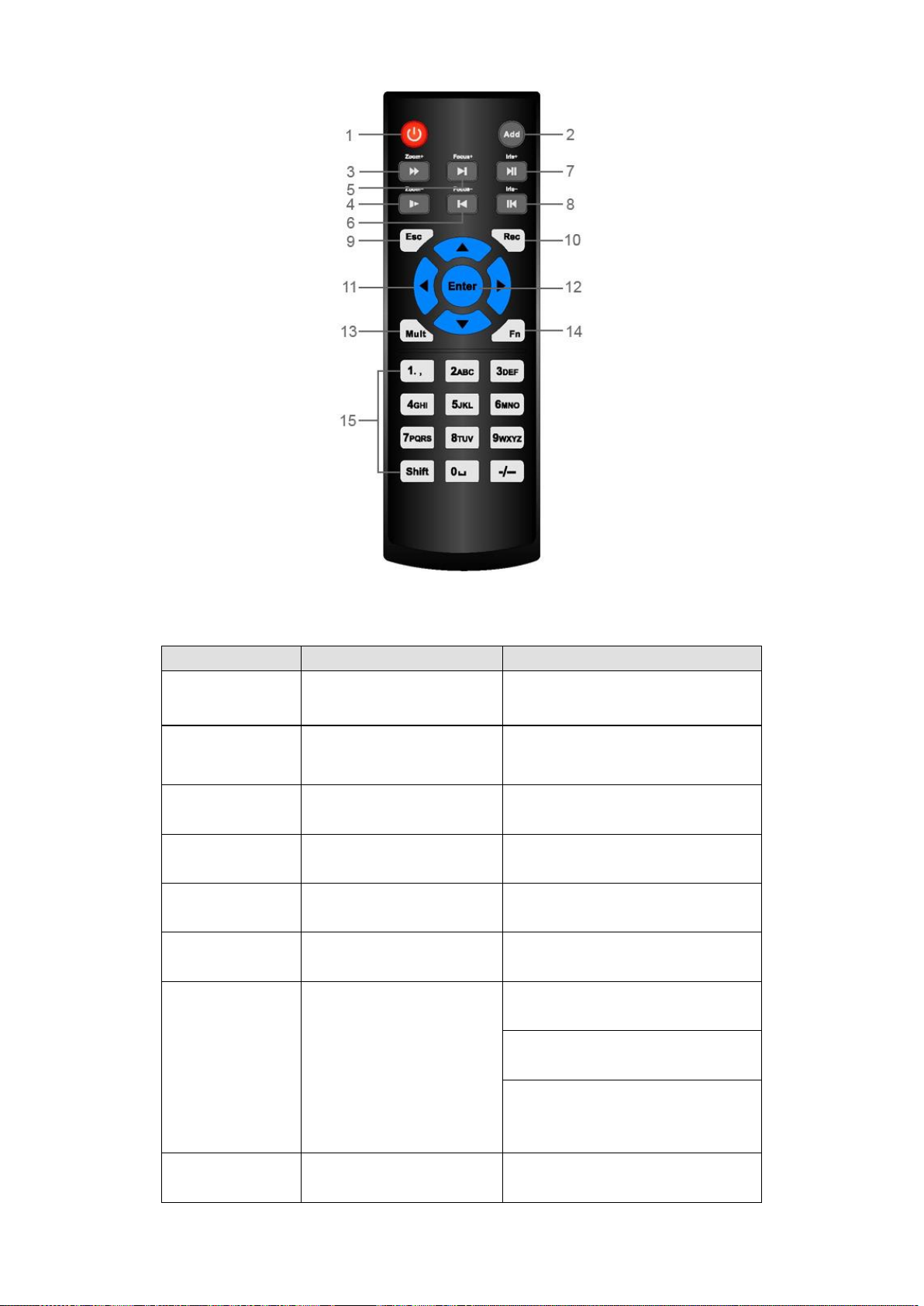
2.3 Remote Control
The remote control interface is shown as in Figure 2-5.
Please note remote control is not our standard accessory and it is not included in the accessory
bag.
Page 20
11
Figure 2-5
Serial Number
Name
Function
1
Power button
Click it to boot up or shut down
the device.
2
Address
Click it to input device number, so
that you can control it.
3
Forward
Various forward speeds and
normal speed playback.
4
Slow play
Multiple slow play speeds or
normal playback.
5 Next record
In playback mode, playback the
next video.
6 Previous record
In playback mode, playback the
previous video.
7
Play/Pause
In pause mode, click this button
to realize normal playback.
In normal playback click this
button to pause playback.
In real-time monitor mode, click
this button to enter video search
menu.
8 Reverse/pause
Reverse playback pause mode,
click this button to realize normal
Please refer to the following sheet for detailed information.
Page 21

12
playback.
In reverse playback click this
button to pause playback.
9 Cancel
Go back to previous menu or
cancel current operation (close
upper interface or control)
10
Record
Start or stop record manually
In record interface, working with
the direction buttons to select the
record channel.
Click this button for at least 1.5
seconds, system can go to the
Manual Record interface.
11
Direction keys
Switch current activated control,
go to left or right.
In playback mode, click up/down
button to switch playback
channel. In 1-window playback
mode, click left/right button to
control playback speed. .
Aux function(such as switch the
PTZ menu, enable/disable reuse
button)
12
Confirm /menu key
go to default button
go to the menu
13
Multiple-window switch
Switch between multiple-window
and one-window.
14
Auxiliary key
In 1-ch monitor mode: pop up
assistant function: PTZ control
and Video color.
Switch the PTZ control menu in
PTZ control interface.
In text mode, click it to delete
character.
15
0-9 number key
Input password, channel or
switch channel.
Shift is the button to switch the
input method.
Left click
mouse
When you have selected one menu item, left click mouse to view menu
content.
Modify checkbox
Click combo box to pop up dropdown list
2.4 Mouse Operation
Please refer to the following sheet for mouse operation instruction.
Page 22
13
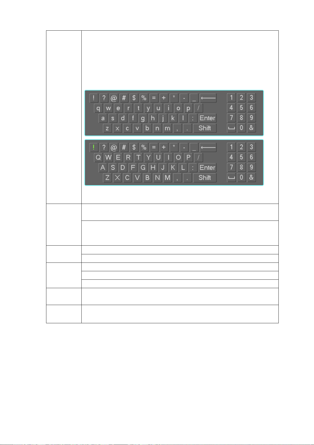
In input box, you can select input methods. Left click the corresponding button
on the panel you can input numeral/English character (small/capitalized). Here
← stands for backspace button. _ stands for space button.
In English input mode: _stands for input a backspace icon and ← stands for
deleting the previous character.
In numeral input mode: _ stands for clear and ← stands for deleting the
previous numeral.
Double left
click mouse
Implement special control operation such as double click one item in the file list
to playback the video.
In multiple-window mode, double left click one channel to view in full-window.
Double left click current video again to go back to previous multiple-window
mode.
Right click
mouse
In real-time monitor mode, pops up shortcut menu.
Exit current menu without saving the modification.
Press
middle
button
In numeral input box: Increase or decrease numeral value.
Switch the items in the check box.
Page up or page down
Move
mouse
Select current control or move control
Drag
mouse
Select privacy mask zone.
Page 23

14
3 Installation and Connections
Note: All the installation and operations here should conform to your local electric safety
rules.
3.1 Check Unpacked NVR
When you receive the NVR from the forwarding agent, please check whether there is any visible
damage. The protective materials used for the package of the NVR can protect most accidental
clashes during transportation. Then you can open the box to check the accessories.
Please check the items in accordance with the list (Remote control is optional). Finally you can
remove the protective film of the NVR.
Note
Remote control is not a standard accessory and it is not included in the accessory bag.
3.2 About Front Panel and Rear Panel
For detailed information of the function keys in the front panel and the ports in the rear panel,
please refer to the appendix for detailed information.
The model in the front panel is very important; please check according to your purchase order.
The label in the rear panel is very important too. Usually we need you to represent the serial
number when we provide the service after sales.
3.3 HDD/SIM Card Installation
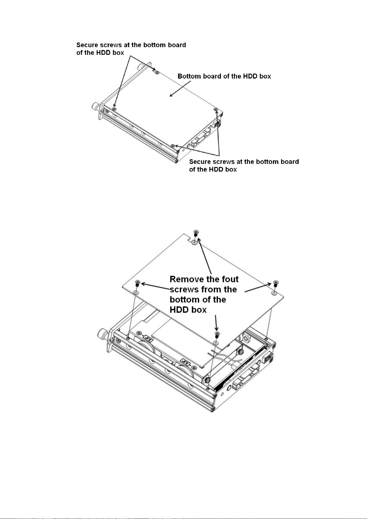
3.3.1 HDD Installation
Important
Shut down the device and unplug the power cable before install/remove the HDD.
The e-lock on the right side of the front panel shall be unlocked when you install/remove the
HDD. Please lock the button before you boot up the device.
The unit you received has no HDD. Please remove the HDD box from the device and then follow
the steps listed below to install.
1) The HDD box and the parts are shown as below. See Figure 3-1. It includes bottom board of
the HDD box and screws.
Page 24
15
Figure 3-1
2) Please loosen the screws of the bottom board of the HDD box and then remove the bottom
board. Now you can see an interface shown as in Figure 3-2.
Figure 3-2
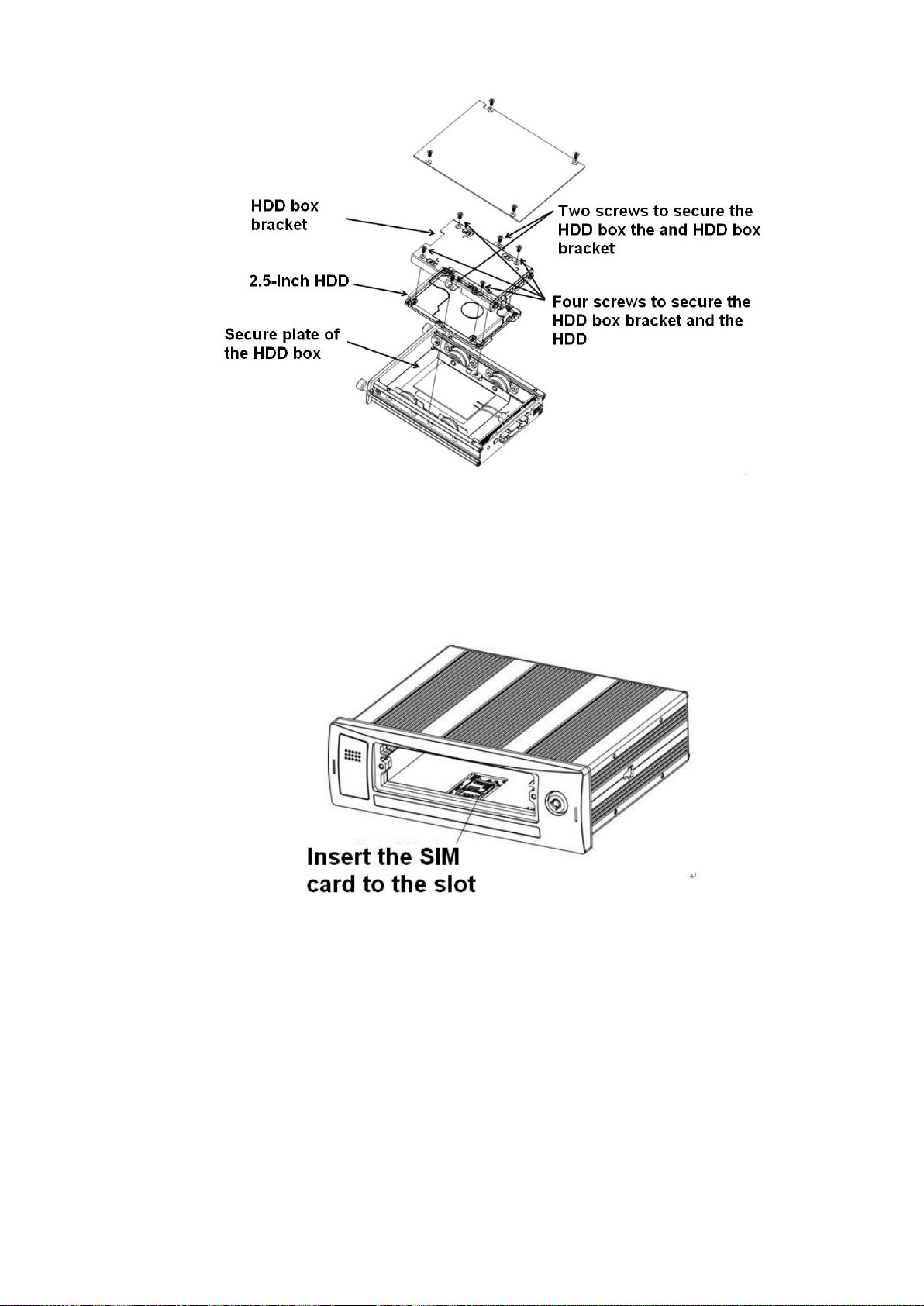
3) Now you can see an interface shown as in Figure 3-3. Use four screws to secure the HDD on
the bracket and then use two screws to fasten the bracket on the bottom board.
Page 25
16
Figure 3-3
3.3.2 SIM Card Installation
This series product supports built-in SIM card. See Figure 3-4.
Remove the HDD box and then open the SIM card slot. Insert the SIM card and then close the
cover.
Figure 3-4
3.4 Connecting Power Supply
Please check input voltage and device power button match or not.
We recommend you use UPS to guarantee steady operation, NVR life span, and other peripheral
equipment operation such as cameras.
3.5 Connecting Audio/Video Input and Output Devices
3.5.1 Audio/Video Input Introduction
System adopts RJ45 network port to input audio/video data.
Page 26
17
Please follow the steps listed below to prepare the network cable and connection.
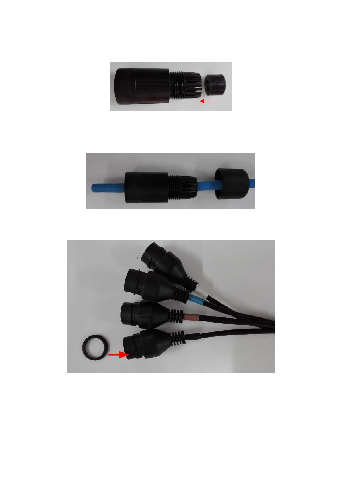
1) Take the following items from the accessories bag and then follow the arrows marked in
Figure 3-5 to insert the plastic gasket.
Figure 3-5
2) Refer to Figure 3-6 to pull the items through the network cable and prepare the crystal
head of the network cable.
Figure 3-6
3) Put the plastic gasket to the head of the network cable. See Figure 3-7.
Figure 3-7
4) Insert the network cable to the network port and then follow the sequence marked in
Figure 3-8 to fasten the jacket.
Page 27
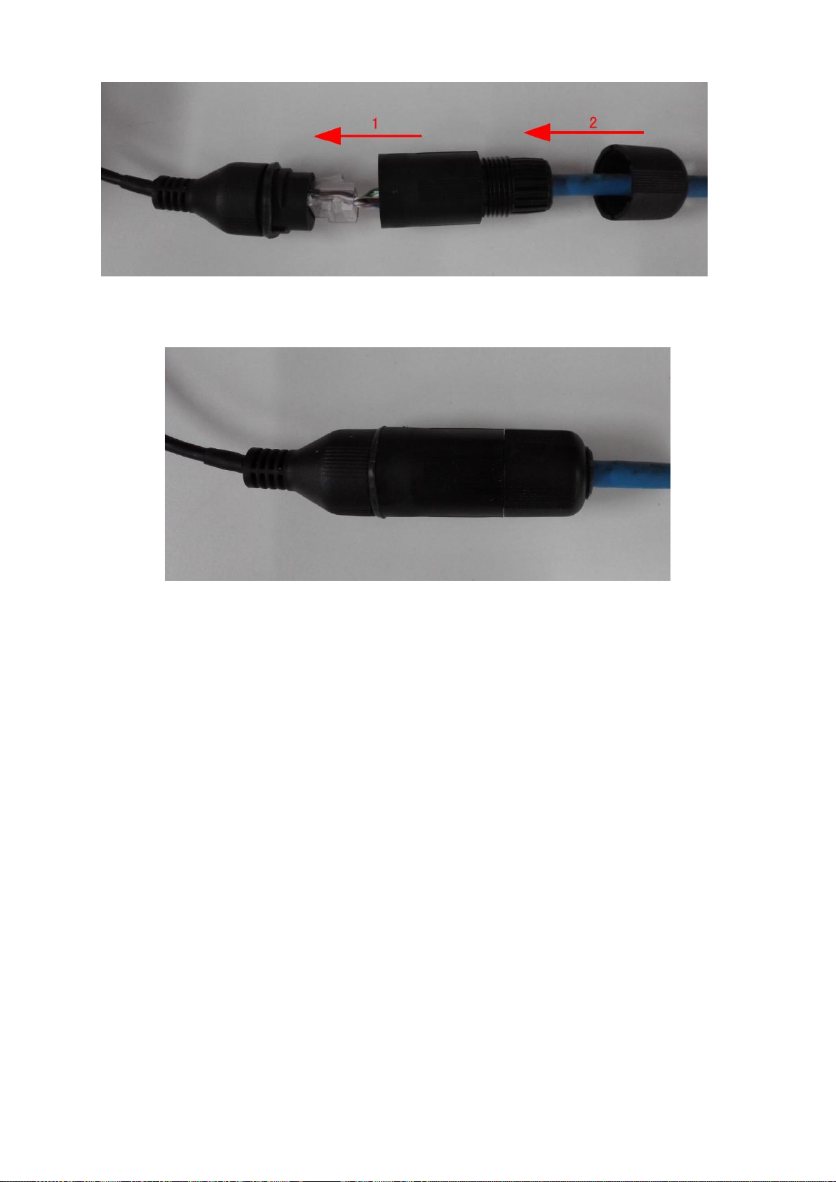
18
Figure 3-8
5) After the connection, you can see the following interface. See Figure 3-9.
Figure 3-9
3.5.2 Audio/Video Output
Video output
Video output includes CVBS(PAL/NTSC 1.0V
When you are using pc-type monitor to replace the monitor, please pay attention to the following
points:
To defer aging, do not allow the pc monitor to run for a long time.
,75Ω)output and a VGA output.
P-P
Regular demagnetization will keep device maintain proper status.
Keep it away from strong electromagnetic interference devices.
Using TV as video output device is not a reliable substitution method. You also need to reduce the
working hour and control the interference from power supply and other devices. The low quality
TV may result in device damage .
Audio Output
The audio output signal parameter is usually over 200mv 1KΩ. It can directly connect to low
impedance earphone, active sound box or amplifier-drive audio output device.
Please refer to Figure 3-10. It is for audio and video output.
Page 28

19
SN
Function
1
12V external power supplying.
Less than 1.5A.
2
GND
3
Audio port
4
Video port
Figure 3-10
3.6 Alarm Input and Output Connection
There are two alarm input types for you to select: normal open (NO) and normal close (NC).
1. Alarm input
a. Alarm input supports grounding alarm input.
b. Alarm input supports 12V voltage signal alarm input.
c. When the alarm device is connecting one NVR and one other device, please use a relay to
separate them,
2. Alarm output
The alarm output max load shall be less than 0.5A. It should not be connected to high power load
directly to avoid high current which may result in relay damage. Please use the co contactor to
realize the connection between the alarm output port and the load.
3. Please make sure the front-end device has soundly earthed.
Improper grounding may result in chip damage.
4. Alarm input type
NO/NC.
3.6.1 Alarm Input and Output Details
Alarm input and output interface is shown as in Figure 3-11.
Page 29
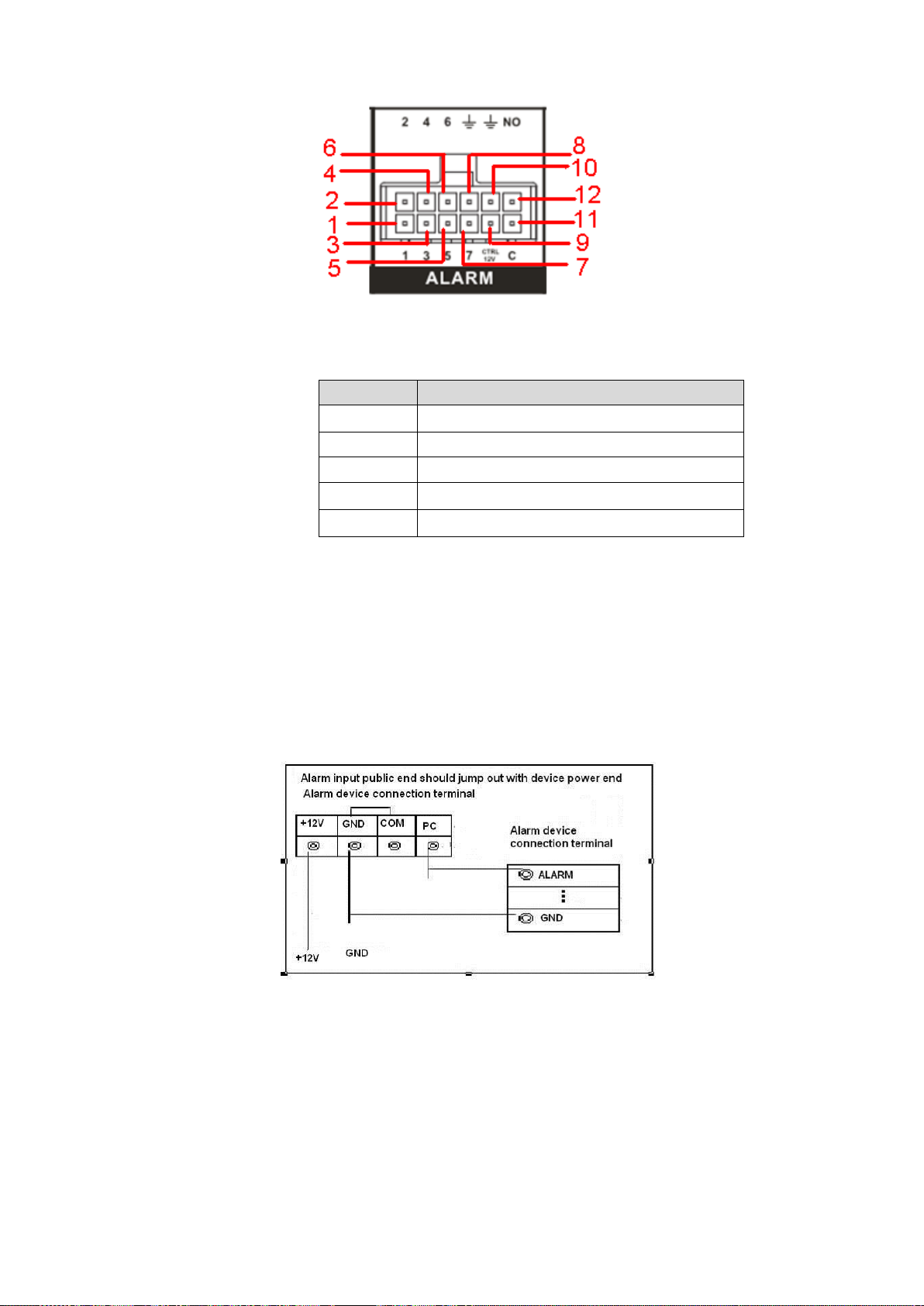
20
Name
Pin Introduction
1~6
Alarm input 1~Alarm input 6
7
Pulse input
8/10
Alarm GND
9
Controllable 12V
11/12
NO/C of alarm output on-off signal
Figure 3-11
Please refer to the following sheet for detailed information.
3.6.2 Alarm Input Port
Please refer to the following sheet for more information. See Figure 3-12.
Normal open or Normal close type.
Please parallel connect COM end and COM end of the alarm detector (Provide external
power to the alarm detector).
Please parallel connect the Ground of the NVR and the ground of the alarm detector.
Please connect the NC port of the alarm sensor to the NVR alarm input(ALARM)
Use the same ground with that of NVR if you use external power to the alarm device.
3.6.3 Alarm Output Port
Alarm output is on-off signal alarm output (NO). Please use additional power supplying for the
peripheral device.
To avoid overloading, please read the following relay parameters sheet carefully.
Figure 3-12
Relay Specification
Page 30

21
Model: HFD23
Contact
Parameter
Contact mode
1Z
Contact resistance
100mΩ(0.1A 6VDC)
Contact material
AgNi+gold-plating
Contact
0.5A 125VAC/1A 30VDC
Max switch voltage
125VAC / 60VDC
Max switch current
2A
Max switch power
62.5VA/30W
Min allowed load
1mA 5V
Mechanical durability
1x10⁷(300/min)
Electric durability
1x10⁵(30/min)
Performance
Parameter
Insulation resistance
1000MΩ(500VDC)
Media
pressure
Between
loop and
1000VAC 1min
Between
separated
contact
400VAC 1min
Operation time (Rated
voltage))
≤5ms
Release time (Rated
voltage)
≤5ms
Bound time (Rated
voltage)
About 5ms
Loop temperature
rise(Rated voltage)
≤65K
Strike
98m/s2
Vibration
10Hz~55 Hz 3.3mm Double amplitude
Humidity
98% RH, 40℃
Temperature
-30℃~70℃
Weight
About 2.2g
leading-out end mode
DIP
Seal mode
Sealed
Loop
Rated Loop Power
Standard mode:200mW; Sensitivity mode:
150mW
Note: All the values listed in the above sheet are initial values.
Page 31

22
4 Operation
Button
Function
Click to restore default setup.
Click to save current setup.
Click to apply current setup.
Click to cancel current setup.
Click to copy current channel setup to other channel.
Click to refresh to get latest information.
4.1 Boot up& Shutdown
Refer to the following sheet for commonly used button definition.
4.1.1 Preparation
Make sure a monitor has properly connected to the video output port of the device. Otherwise
there is no video output.
Check there is a work-write HDD or not, otherwise device cannot record.
4.1.2 Boot up
Boot up
Turn the key from “ ” to “ ”, the power indicator light becomes on. It may take a while for the
device to boot up. It goes to multiple-window preview mode by default after booted up. You can
see the corresponding record status indictor light if system is recording after booted up.
After booted up, system is in multiple-window mode and schedule record status by default. The
record indicator light becomes on too if the device is in the record period.
In the default setup, the device will automatically shut down after the ACC power is
disconnected.
The ACC delay value ranges from 0 to 65535 (Unit: minute). System can delay shutting down
for the specified time and then turn off(Main menu->Setting->System->Auto maintenance).
Auto record
System enables schedule record function if the boot up is within the specified period. You can
see the corresponding record indicator light becomes on and system runs normally.
4.1.3 Change Password
For your own safety, please change your administrator default password after your first
login.
Page 32

23
After system booted up, you can see the following interface if it is your first login or you have
restored default setup. See Figure 4-1. Please input old password and then input new password
twice to confirm the change.
The default administrator user name is admin and the password is admin.
You can set security questions here to reset the password in case you forgot. System
supports customized setup. Please note you need to set two security questions at the same
time. When you reset the password, you need to answer these two security questions too.
For reset information, please refer to chapter 4.1.4.
Figure 4-1
Click Cancel button, system pops up the following interface for you to confirm. See Figure 4-2.
Check the box here, system will not pop up the change password interface the next time.
Figure 4-2
4.1.4 Reset Password
Once you forgot password, you can answer the security questions you set in chapter 4.1.3 to
reset the password.
Page 33

24
In login interface, click . See Figure 4-3.
Figure 4-3
System pops up the following dialogue box, please answer the security questions and then input
the new password twice. See Figure 4-4.
Figure 4-4
4.1.5 Startup Wizard
Important
From main menu->Setting->System->General, you can enable/disable Startup wizard function.
After you successfully set the password, it goes to startup wizard.
Click Cancel/Next button, you can see system goes to login interface.
Tips
Check the box Startup button here, system goes to startup wizard again when it boots up the next
Page 34

25
time.
Cancel the Startup button, system goes to the login interface directly when it boots up the next
time.
Figure 4-5
Click Cancel button or Next Step button, system goes to login interface. See Figure 4-6.
System consists of three accounts:
Username: admin. Password: You set in chapter 4.1.3.
Username: 888888. Password: 888888. (administrator, local only)
Username: default. Password: default (hidden user). Hidden user “default” is for system
interior use only and cannot be deleted. When there is no login user, hidden user “default”
automatically login. You can set some rights such as monitor for this user so that you can
view some channel view without login.
Figure 4-6
Caution
For security reason, please modify password after you first login.
Page 35

26
Continuous three times login failure will result in system alarm and five times login failure will
result in account lock!
Please reboot the device or wait for 30 minutes to try again if your account has been locked.
After input corresponding user name and password, you can click OK button. System goes to the
startup wizard.
4.1.6 General
Tips:
From main menu->Setting->System->General, you can also go to the following interface.
4.1.6.1 General
Click OK button, you can go to General interface. See Figure 4-7. Please refer to chapter 4.15.1
for detailed information.
Figure 4-7
4.1.6.2 Date and Time
The interface is shown as in Figure 4-8. Please refer to chapter 4.15.1 for detailed information.
Page 36

27
Figure 4-8
4.1.7 Network
Tips:
From main menu->Setting->Network->TCP/IP, you can also go to the following interface.
Click Next button, you can go to network interface. See Figure 4-9. Please refer to chapter 4.13.1
for detailed information.
Page 37

28
Figure 4-9
4.1.8 Remote
Tips
From the main menu->Setting->Camera->Remote, or on the preview window and then right click
mouse and then select Remote, you can go to the following interface.
Click Next button, you can go to the Remote interface to add the camera to the corresponding
channel. See Figure 4-10. Please refer to chapter 4.5.1 for detailed information.
Page 38

29
Figure 4-10
4.1.9 Schedule
Tips:
From main menu->Setting->Storage->Schedule, you can also go to the following interface.
Click Next button, you can go to Schedule interface. See Figure 4-11. Please refer to chapter
4.8.2.1 for detailed information.
Page 39

30
Figure 4-11
Click Finish button, system pops up a dialogue box. Click the OK button, the startup wizard is
complete. See Figure 4-12.
Figure 4-12
4.2 Preview
4.2.1 Preview Interface
After you successfully logged in, you can go to preview interface directly. See Figure 4-13. You
can overlay the corresponding date, time and channel name on each screen.
Page 40

31
Icon
Note
Display network connection status. It includes 3G/4G,
GPS, WIFI, and DSS.
The grey and a cross means there is no connection.
The highlighted icon means the connection is OK.
ACC ON和 ACC OFF。Display ACC status. It includes
ACC O/ACC OFF.
Display system date and time.
Display device working voltage
Display current working temperature
Display current longitude and latitude.
Display current speed.
Display plate information.
You can refer to the following sheet for detailed information.
The preview interface is shown as in Figure 4-11
Figure 4-13
Page 41

32
Figure 4-14
Icon
Note
Search
Click to go to Search interface. Please refer to chapter 4.10 for
detailed information.
IVS
Click to go to IVS interface. This function supports customized
development and setup.
Backup
Click to go to Backup interface. Please refer to chapter 4.15.9 for
detailed information.
Settings
Click to go to Setup interface. Please refer to chapter 4.15 for
detailed information.
Info
Click to go to information interface. Please refer to chapter 4.16,
chapter 4.17, chapter 4.18 and chapter 4.19 for detailed information.
Shutdown
Click to go to shut down interface. Please refer to chapter 4.19.1 for
detailed information.
You can refer to the following sheet for detailed information.
4.3 Right-Click Menu
On the preview interface, right click mouse, you can view menu interface shown as in Figure
4-15.
Figure 4-15
Please refer to the following sheet for detailed information.
Page 42

33
Name
Function
1/4-window
System supports 1/4-window.
PTZ control
Click to go to PTZ control interface. please refer to chapter
4.6.2 to set PTZ parameter
Fisheye
It is to set fisheye installation mode and display mode. Please
refer to chapter 4.7 to set.
Search
Click to go to the search interface. Please refer to chapter
4.5 to set.
Manual
It includes the following items:
Record control. Please refer to chapter to set.
Alarm control. Please refer to chapter 4.8.2.2 to set.
PTZ Fn. Please refer to chapter 4.12.2 to set.
PTZ shutter. Please refer to chapter 4.12.3 to set.
Remote device
Search and add remote device. Please refer to chapter 4.5.1
to set.
Main menu
Click to go to the main menu. Please refer to chapter 4.4 to
set.
4.4 Main Menu
On the preview window, right click mouse, and the select main menu, system pops up login
dialogue box. See Figure 4-16.
Figure 4-16
After you logged in, the system main menu is shown as below. See Figure 4-17.
Page 43

34
Figure 4-17
4.5 Remote Device
4.5.1 Remote Device
From Main menu->Setting->Camera->Remote->Remote or right click mouse on the preview
interface and then select Remote item, you can see the following interface. See Figure 4-18.
Figure 4-18
Page 44

35
Search remote device
Click Device search button, you can view the searched IP addresses at the top pane of the
interface.
Note
You can use IP address or MAC address to search device. System supports fuzzy search.
For the device in the added device list, you can not see it at the top pane of the interface.
Click , you can view the video of current camera.
Double click an IP address or check one or more IP address (es) at the same time and then click
Add button, you can add current device to the added devices at the bottom pane of the interface.
System supports batch add function.
Add remote device
Click Manual Add button, you can add a device directly. Here you can set TCP/UPD/auto
connection mode. The default setup is TCP. See Figure 4-19.
Manufacturer: Select the manufacture from the dropdown list.
IP address: Input remote IP address.
TCP port: Input TCP port value.
RTSP port: Input RTSP port value. Please note this value is for ONVIF protocol only.
HTTP port: Input HTTP port value. Please note this value is for ONVIF protocol only.
User name: Input the user name you login the remote device.
Password: Input the password you login the remote device.
Channel amount: It is to display channel total amount. Click Set button to set remote device
channel so that you can control remotely.
Remote channel amount: The channel mount of the remote device.
Channel: The channel mount of current device. It is the channel amount you want to view the
remote device.
Decode buffer: Please select from the dropdown list: default/realtime/fluency.
Important
Please note the manual add function is for Dahua, Panasonic, Sony, Dynacolor, Samsung, AXIS,
Arecont, ONVIF and Custom. When the type is the custom, you can just input URL address, user
name and password connect to the network camera without considering network camera
manufacture. Please contact your network camera manufacturer for the URL address.
Page 45

36
Figure 4-19
Change IP address
On the searched devices list, check one or more device(s) at the same time. Click Modify IP
button , you can see the following interface. See Figure 4-20.
DHCP: Check the box here, system can auto allocate the IP address. The IP address, subnet
mask, default gateway are reference only.
Static: Check the box here, you can set IP address, subnet mask, default gateway manually.
IP address/subnet mask/default gateway: You can input corresponding information here.
User name/password: The account you login the remote device. Please input here to
password verification to change the remote device password.
Incremental value: When you want to change several IP addresses, once you input the IP
address of the first device, the IP address of the next device will increase accordingly. For
example, when the incremental value is 1, if the IP address of the first device is 172.10.3.128,
the IP address of the second device will auto be set as 172.10.3.129.
Note
For the static IP address, system will alert you if there is any IP conflict. If you are changing
several IP addresses at the same time, system auto skip the conflicted IP and auto allocate
again according to the incremental value you set.
Page 46

37
Figure 4-20
4.5.2 Short-Cut Menu
In the preview interface, you can click the icon “+” in the centre of the interface to quickly go to the
Remote Device interface. See Figure 4-21.
Figure 4-21
4.5.3 Channel Name
From main menu->Setting->Camera->Channel name, you can see an interface shown as in
Figure 4-22.
It is to modify channel name. It max supports 31-character.
Please note you can only modify the channel name of the connected network camera.
Page 47

38
Figure 4-22
4.5.4 Upgrade
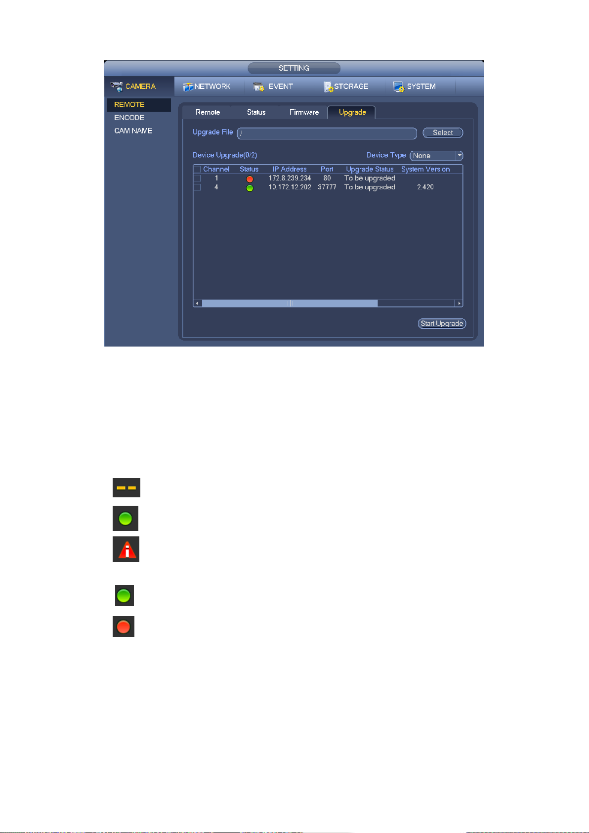
Important
System max supports to upgrade 4 online network cameras at the same time.
It is to update the network camera.
From main menu->Setting->Camera->Remote->Upgrade, the interface is shown as below. See
Figure 4-23.
Click Browse button and then select the upgrade file. Then select a channel (or you can select
device type filter to select several devices at the same time.)
Click Start upgrade button to upgrade. You can see the corresponding dialogue once the upgrade
is finish.
Page 48
39
Figure 4-23
4.5.5 Device Status
From main menu->Setting->Remote->Status, here you can view the IPC status of the
corresponding channel such as motion detect, video loss, tampering, alarm and etc. See Figure
4-24.
IPC status:
: Front-end does not support.
: Front-end supports.
: There is alarm event from current front-end.
Connection status
: : Connection succeeded.
: Connection failed.
Refresh: Click it to get latest front-end channel status.
Page 49

40
Figure 4-24
4.5.6 Firmware
From main menu->Setting->Remote->Firmware, it is to view channel, IP address, manufacturer,
type, system version, SN, video input, audio input, external alarm and etc. See Figure 4-25.
Figure 4-25
Page 50

41
4.6 PTZ Control
Please make sure the camera supports PTZ function.
4.6.1 PTZ Settings
Cable Connection
Please follow the procedures below to go on cable connection
Connect the dome RS485 port to NVR RS485 port.
Connect dome video output cable to NVR video input port.
Connect power adapter to the dome.
In the main menu, from Setting->System->PTZ, you can see an interface is shown as in
Figure 4-26. Here you can set the following items:
Channel: Select the current camera channel.
PTZ type: There are two types: local/remote. Please select local mode if you are connect
RS485 cable to connect to the Speed dome (PTZ). Please select remote mode if you are
connecting to the network PTZ camera.
Protocol: Select corresponding PTZ protocol(such as PELCOD)
Address: Default address is 1.
Baud rate: Select corresponding baud rate. Default value is 9600.
Data bit: Select corresponding data bits. Default value is 8.
Stop bit: Select corresponding stop bits. Default value is 1.
Parity: There are three options: odd/even/none. Default setup is none.
Figure 4-26
If you are connecting to network PTZ, the PTZ type shall be remote. See Figure 4-27.
Page 51

42
Figure 4-27
4.6.2 PTZ Control
After completing all the setting please click save button. Right click mouse (click “Fn” Button in
the front panel or click “Fn” key in the remote control). The interface is shown as in Figure
4-28. Please note you can only go to the PTZ control interface when you are in 1-window
display mode.
Figure 4-28
The PTZ setup is shown as in See Figure 4-29.
Please note the commend name is grey once device does not support this function.
The PTZ operation is only valid in one-window mode.
Here you can control PTZ direction, speed, zoom, focus, iris, preset, tour, scan, pattern aux
function, light and wiper, rotation and etc.
Speed is to control PTZ movement speed. The value ranges from 1 to 8.The speed 8 is faster
Page 52

43
than speed 1. You can use the remote control to click the small keyboard to set.
Name
Function
key
function
Shortcut
key
Function
key
function
Shortcut
key
Zoom
Near
Far
Focus
Near
│
Far
►│
Iris close
Open
You can click and of the zoom, focus and iris to zoom in/out, definition and brightness.
The PTZ rotation supports 8 directions. If you are using direction buttons on the front panel, there
are only four directions: up/down/left/right.
Figure 4-29
In the middle of the eight direction arrows, there is a 3D intelligent positioning key. See Figure
4-30. Please make sure your protocol supports this function and you need to use mouse to
control.
Click this key, system goes back to the single screen mode. Drag the mouse in the screen to
adjust section size. The dragged zone supports 4X to 16X speeds. It can realize PTZ
automatically. The smaller zone you dragged, the higher the speed.
Figure 4-30
in Figure 4-29 is the high speed PTZ. Click , you can use mouse to drag the
interface to the left or to the right; it is easy to pinpoint the position.
In Figure 4-29, click to open the menu, you can set preset, tour, pattern, scan and etc.
See Figure 4-31 .
Page 53

44
Icon
Function
Icon
Function
Preset
Flip
Tour
Reset
Pattern
Aux
Scan
Aux on-off
button
Rotate
Go to menu
Figure 4-31
Please refer to the following sheet for detailed information.
Please note the above interface may vary due to different protocols. The button is grey and
can not be selected once the current function is null.
Right click mouse or click the ESC button at the front panel to go back to the Figure 4-29.
4.6.2.1 PTZ Function Setup
Click , you can go to the following interface to set preset, tour, pattern, and scan. See Figure
4-32.
Figure 4-32
Page 54

45
Preset Setup
In Figure 4-32, click preset button and use eight direction arrows to adjust camera to the proper
position. The interface is shown as in Figure 4-33.
Click Set button and then input preset number.
Click Set button to save current preset.
Figure 4-33
Tour Setup
In Figure 4-32, click tour button.
Input tour value and preset No. Click Add preset button to add current preset to the tour. See
Figure 4-34.
Tips
Repeat the above steps to add more presets to the tour. Click Del preset button to remove it from
the tour. Please note some protocols do not support delete preset function.
Figure 4-34
Pattern Setup
In Figure 4-32, click Pattern button and input pattern number.
Click Begin button to start direction operation. Or you can go back to Figure 4-29 to operate
zoom/focus/iris/direction operation.
Page 55

46
In Figure 4-32, click End button.
Figure 4-35
Scan Setup
In Figure 4-32, click Scan button.
Use direction buttons to set camera left limit and then click Left button.
Use direction buttons to set camera right limit and then click Right button. Now the scan setup
process is complete.
Figure 4-36
4.6.2.2 Call PTZ Function
Call Preset
In Figure 4-31 , input preset value and then click to call a preset. Click again to
stop call.
Call Pattern
In Figure 4-31, input pattern value and then click to call a pattern. Click again to
stop call.
Page 56

47
Call Tour
In Figure 4-31 , input tour value and then click to call a tour. Click again to stop
call.
Call Scan
In Figure 4-31 , input Scan value and then click to call a tour. Click again to stop
call.
Rotate
In Figure 4-31, click to enable the camera to rotate.
System supports preset, tour, pattern, scan, rotate, light and etc function.
Note:
Preset, tour and pattern all need the value to be the control parameters. You can define it as
you require.
You need to refer to your camera user’s manual for Aux definition. In some cases, it can be
used for special process.
Aux
Click , system goes to the following interface. The options here are defined by the protocol.
The aux number is corresponding to the aux on-off button of the decoder. See Figure 4-37.
Figure 4-37
4.7 Fisheye
4.7.1 Fisheye de-warp during preview interface
On the preview interface, select fisheye channel and then right click mouse, you can select
Page 57

48
fisheye. Now you can see an interface shown as in Figure 4-38. You can set fisheye installation
Installation modes
Icon
Note
(Ceiling mount)
(Ground mount)
360°panorama original view
1 de-warp window+1 panorama stretching
2 panorama stretching view
1 360° panorama view+3 de-warp windows
1 360°panorama view+4 de-warp windows
4 de-warp windows+1 panorama stretching
mode and display mode.
Note:
For the non-fisheye channel, system pops up dialogue box to remind you it is not a fisheye
channel and does not support de-warp function.
If system resources are insufficient, system pops up the corresponding dialogue box too.
There are three installation modes: ceiling mount/wall mount/ground mount. The different
installations modes have different de-warp modes.
Please refer to the following sheet for detailed information.
Figure 4-38
Page 58

49
1 360° panorama view+8 de-warp windows
(Wall mount)
360°panorama original view
Panorama stretching
1 panorama unfolding view+3 de-warp
windows
1 panorama unfolding view +4 de warp
windows
1 panorama unfolding view +8 de warp
windows
Figure 4-39
In Figure 4-39, you can adjust the color pane on the left pane or use your mouse to change
the position of the small images on the right pane to realize fisheye de -warp.
Please use the mouse to zoom in/zoom out, move/rotate the image. (Please note this function
is not for wall mount mode)
4.7.2 Fisheye de-warp during playback
On the main menu, click search button.
Select 1-window playback mode and corresponding fisheye channel, click to play.
Right click the , you can go to the de-warp playback interface. For detailed information,
please refer to chapter 4.7.1.
4.8 Record
4.8.1 Encode
The record/snapshot priority is: Alarm->Motion detect->Schedule.
Page 59

50
4.8.1.1 Encode
Encode setting is to set network camera encode mode, resolution, bit stream type and etc.
From Main menu->Setting->Camera->Encode->Encode, you can see the following interface. See
Figure 4-40.
Channel: Select the channel you want.
Type: Please select from the dropdown list. There are three options: regular/alarm. You can
set the various encode parameters for different record types.
Compression: System supports H.264, H.264H, H.265 and etc.
Resolution: The mainstream resolution type is IPC’s encoding config uration. System max
supports 4K.
Frame rate: It ranges from 1f/s to 25f/s in NTSC mode and 1f/s to 30f/s in PAL mode.
Bit rate type: System supports two types: CBR and VBR. In VBR mode, you can set video
quality.
Video/audio: You can enable or disable the video/audio. Please note, once you enable audio
function for one channel, system may enable audio function of the rest channels by default.
Audio encode: Please select audio encode mode from the dropdown list. It includes:
PCM/G711A/G711Mu/AAC.
Copy:After you complete the setup, you can click Copy button to copy current setup to other
channel(s). You can see an interface is shown as in Figure 4-47. You can see current
channel number is grey. Please check the number to select the channel or you can check the
box ALL. Please click the OK button in Figure 4-47 and Figure 4-41 respectively to complete
the setup. Please note, once you check the All box, you set same encode setup for all
channels. Audio/video enable box, overlay button and the copy button is shield.
Please highlight icon to select the corresponding function.
Figure 4-40
Page 60

51
4.8.1.2 Overlay
From Main menu->Setting->Camera->Encode->Overlay, you can see an interface is shown in
Figure 4-41.
Cover area: Here is for you to cover area section. You can drag you mouse to set proper
section size. In one channel video, system max supports 4 zones in one channel. You can set
with Fn button or direction buttons.
Preview/monitor: The cover area has two types. Preview and Monitor. Preview means the
privacy mask zone can not be viewed by user when system is in preview status. Monitor
means the privacy mask zone can not be view by the user when system is in monitor status.
Time display: You can select system displays time or not when you playback. Please click set
button and then drag the title to the corresponding position in the screen.
Channel display: You can select system displays channel number or not when you playback.
Please click set button and then drag the title to the corresponding position in the screen.
Plate Title. : You can select system displays car number or not when you playback.
GPS display: You can select system displays latitude and longitude or not when you
playback.
Figure 4-41
4.8.2 Schedule
The record type priority is: Alarm>Regular.
4.8.2.1 Schedule Record
It is to set record time, record plan and etc. Please note system is in 24-hour record by default
after its first boot up.
Page 61

52
In the main menu, from Main menu->Setting->Storage->Schedule, you can go to schedule
menu. See Figure 4-45. There are total six periods.
Channel: Please select the channel number first. You can select “all” if you want to set for the
whole channels.
: Sync connection icon. Select icon of several dates, all checked items can be
edited or together. Now the icon is shown as .
: Click it to delete a record type from one period.
Record Type: Please check the box to select corresponding record type. There are two types:
Regular/Alarm.
Week day: There are eight options: ranges from Saturday to Sunday and all.
Pre-record: System can pre-record the video before the event occurs into the file. The value
ranges from 0 to 30 seconds depending on the bit stream.
Period setup: Click button after one date or a holiday, you can see an interface shown
as in Figure 4-46.There are five record types: regular, motion detection (MD), Alarm, MD &
alarm, and intelligence.
Please following the steps listed below to draw the period manually.
a) Select a channel you want to set. See Figure 4-42.
Figure 4-42
b) Set record type. See Figure 4-43.
Figure 4-43
c) Please draw manually to set record period. There are six periods in one day. See Figure
4-44.
Figure 4-44
Page 62

53
Please check the box to select the corresponding function. After completing all the setups
please click save button, system goes back to the previous menu.
Figure 4-45
Figure 4-46
Page 63

54
Quick Setup
Copy function allows you to copy one channel setup to another. After setting in channel 1, click
Copy button, you can go to interface Figure 4-47. You can see current channel name is grey such
as channel 1. Now you can select the channel you want to paste such as channel 5/6/7. If you
want to save current setup of channel 1 to all channels, you can click the first box “ALL”. Click the
OK button to save current copy setup. Click the OK button in the Encode interface, the copy
function succeeded.
Please note, if you select ALL in Figure 4-47, the record setup of all channels are the same and
the Copy button becomes hidden.
Figure 4-47
Click OK button to save current setup.
4.8.2.2 Record Control
From Main menu->Setting->Storage->Record or on the preview interface, right click mouse and
then select record item, you can see Figure 4-48.
Manual: The highest priority. After manual setup, all selected channels will begin ordinary
recording.
Auto: Channel records as you have set in recording setup (Main
Menu->Setting->Storage->Schedule)
Off : All channels stop recording.
Select a channel and enable record function, click Save button.
Page 64

55
Figure 4-48
4.9 Snapshot
Note
Please note the manual snapshot has the higher priority than schedule snapshot. If you have
enabled these two types at the same time, system can activate the trigger snapshot when an
alarm occurs, and otherwise system just operates the regular snapshot.
Only the trigger snapshot supports this function. The regular snapshot function cannot send
out picture via the email. But you can upload the picture to a FTP.
4.9.1 Snapshot Setup
In the main menu, from Main menu->Setting->Storage->Schedule->Snapshot, you can go to
schedule menu. See Figure 4-49. Please refer to chapter 4.8.2.1 for detailed setup
information.
Page 65

56
Figure 4-49
4.9.2 Schedule Snapshot
From Main menu->Setting->Camera->Encode->Snapshot, you can go to snapshot interface. See
Figure 4-50.
Select the snapshot channel from the dropdown list and then select snapshot mode as Timing
(Schedule) from the dropdown list and then set picture size, quality and snapshot frequency.
Snapshot mode: There are two modes: Timing (Schedule) and activation. If you set timing
mode, you need to set snapshot frequency. If you set activation snapshot, you need to go to
Detect interface (Main menu->Setting-Detect) to set snapshot activation operation.
Image size: Here you can set snapshot picture size.
Image quality: Here you can set snapshot quality. The value ranges from 1 to 6.
Interval: It is for you to set timing (schedule) snapshot interval. The value ranges from 1-7
picture(s) per second.
Page 66
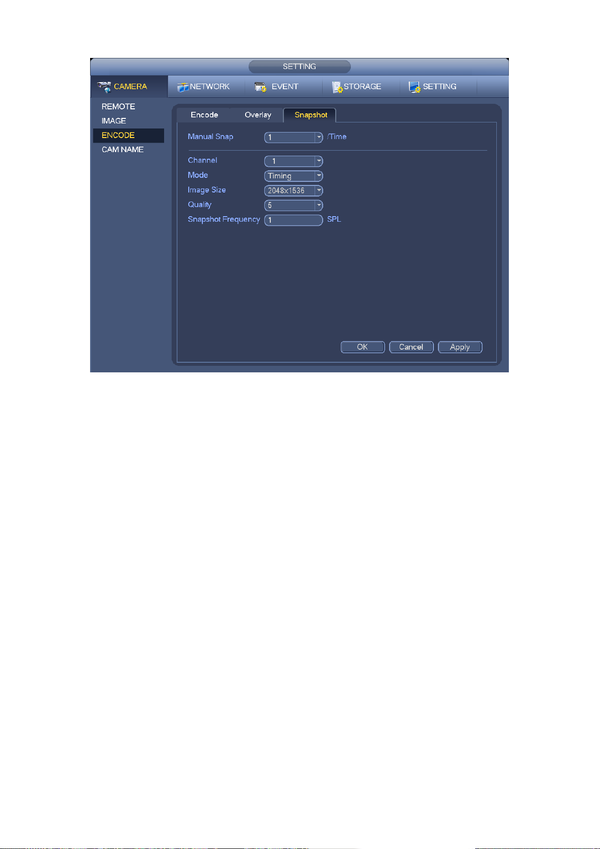
57
Figure 4-50
4.9.3 Event Snapshot
From Main menu->Setting->Camera->Encode->Snapshot, you can go to the following interface.
See Figure 4-51.
Select the snapshot channel from the dropdown list and then select snapshot mode as Trigger
from the dropdown list and then set picture size, quality and snapshot frequency. Please refer to
chapter 4.9.2 for detailed information.
Page 67

58
Figure 4-51
In the main menu, from Setting->Event-> Alarm, you can see alarm setup interface. Check the
box to enable snapshot function when an alarm occurs. See Figure 4-52.
Figure 4-52
Page 68

59
From Main menu->Setting->Storage->Schedule, you can go to Figure 4-53 to enable snapshot
function when an event occurs.
Figure 4-53
4.9.4 Enable/Disable Snapshot
On the preview window, right click mouse and select manual record, or in the main menu, from
Setting->Storage->Record, you can go to record interface. See Figure 4-54. Here you can
enable or disable snapshot function.
Page 69

60
Figure 4-54
4.10 Search & Playback
4.10.1 Search Interface
From Main menu->Operation->Search, or on the preview interface right click mouse and then
select search item; you can go to the following interface. See Figure 4-55.
Page 70

61
Figure 4-55
SN
Name
Function
1
Display window
Here is to display the searched picture or file.
Support 1/4-window playback.
2
Playback control
bar
From left to right: play/pause, stop, backward, previous frame, last
frame, slow play, fast play, volume.
Note:
All the operations here (such as playback speed, channel, time and
progress) have relationship with hardware version. Some series
NVRs do not support some functions or playback speeds.
3
Time bar
It is to display the record type and its period in current search criteria.
4
Playback status
and record type
Playback status: Display current play status. It includes start play,
pause play, stop play, backward, fast play and slow play.
Record type: General/alarm. Check the box to select a record type,
the time bar displays corresponding file information.
5
Time bar unit
The option includes: 24H, 12H, 1H and 30M. The smaller the unit, the
larger the zoom rate. You can accurately set the time in the time bar to
playback the record.
6
Clip
It is to edit the file and save the footages you want.
Please refer to the following sheet for more information.
Page 71

62
SN
Name
Function
7
Record type
In any play mode, the time bar will change once you modify the search
type.
8
Fisheye dewarp
In 1-channel playback mode, click it; you can see fisheye setup
interface on the right pane. You can set fisheye installation mode and
display mode to de-warp the record. Please refer to chapter 4.7.2 for
detailed information.
9
Playback mode
and channel
Playback mode:1/4-channel.
The time bar will change once you modify the playback mode or
the channel option.
10
Calendar
The blue highlighted date means there is picture or file. Otherwise,
there is no picture or file.
In any play mode, click the date you want to see, you can see the
corresponding record file trace in the time bar.
11
Search type
Here you can select to search the picture or the recorded file.
You can select to play from the read-write HDD, from peripheral
device or from redundancy HDD.
Before you select to play from the peripheral device, please
connect the corresponding peripheral device. You can view all record
files of the root directory of the peripheral device. Click the Browse
button; you can select the file you want to play.
4.10.2 Clip
This function allows you to clip some footages to a new file and then save to the USB device. See
Figure 4-56. Please follow the steps listed below.
a) Select a record first and then click to playback.
b) Select a time at the time bar and then click to start clip,
c) Select a time at the time bar and then click to stop clip,
d) Click , system pops up dialogue box to save the clip file.
Figure 4-56
4.10.3 Picture Playback
a) From Main menu->Search, or on the preview interface right click mouse, you can go to Figure
4-55.
b) At the top right pane, you can check the box to select picture and then select playback
interval. See Figure 4-57. It is to view the schedule snapshot and event snapshot images.
Page 72

63
c) Please refer to chapter 4.10.1 to select a picture you want to view.
Figure 4-57
4.11 Event
4.11.1 Video Detect
In the main menu, from Setting to Video Detect, you can see an interface shown as in Figure
4-58. There are two detection types: video loss/tampering.
You can see video loss icon if current channel has enabled video loss alarm.
4.11.1.1 Video Loss
You can follow the steps listed below to set video loss alarm.
a) From Main menu->Setting->Event->Video Loss to set video loss item and enable this
function.
b) Select video loss channel.
Video loss is shown as below. See Figure 4-58.
Event type: From the dropdown list you can select video loss type.
Channel: Select a channel from the dropdown list to set video loss function.
Enable: Check the box here to enable video loss function.
Alarm output: when an alarm occurs, system enables peripheral alarm devices.
Latch: when video loss is complete, system auto delays detecting for a specified time. The
value ranges from 1-300(Unit: second)
Show message: System can pop up a message to alarm you in the local host screen if you
enabled this function.
Alarm upload: System can upload the alarm signal to the network (including alarm centre)
if you enabled current function.
Send email: System can send out email to alert you when an alarm occurs.
Record channel: Select the channel to activate recording function once an alarm occurred.
Please make sure you have set schedule record in encode interface(Main
Menu->Setting->Storage->Schedule) and auto record in manual record interface(Main
Menu->Setting->Storage->Record)
Record Delay: System can delay the record for specified time after alarm ended. The value
ranges from 10s to 300s.
Snapshot: You can enable this function to snapshot image when video loss alarm occurs.
Buzzer: Highlight the icon to enable this function. The buzzer beeps when an alarm occurs.
Please highlight icon to select the corresponding function. After all the setups please click
Page 73

64
save button, system goes back to the previous menu.
Tips:
You can enable preset/tour/pattern activation operation when video loss occurs.
Figure 4-58
4.11.1.2 Tampering
When someone viciously masks the lens, or the output video is in one-color due to the
environments light change, the system can alert you to guarantee video continuity.
From Main menu->Setting->Event->Tampering, you can set tampering item and enable this
function. See Figure 4-59. You can enable alarm output channel and then enable show
message function. You can refer to chapter4.11.1.1 Video Loss for detailed information.
Note:
In Video Detect interface, copy/paste function is only valid for the same type, which means
you can not copy a channel setup in video loss mode to tampering mode.
Page 74

65
Figure 4-59
4.11.2 Alarm Setup
From Main menu->Setting->Event->Alarm, You can follow the steps listed below to set.
a) You can connect the external alarm port from the rear panel of the device. Usually the
vehicle left-turn, right-turn, brake and door signal information and etc can be input to the
device via the alarm input device.
b) In the main menu, from Setting to Alarm, you can see alarm setup interface. See Figure
5-34.
c) You can set its actual alarm name such as left-turn, right-turn on the Alarm Name item.
Check the Overlay button, you can overlay corresponding alarm information on the record
file.
d) If the alarm signal is 12V/24V voltage, the trigger type shall be high valid. If the alarm
signal is ground signal, the trigger type shall be low valid.
e) The normal open means the alarm signal is usually disconnect, system can generate an
alarm when the alarm signal closed. The normal close means the alarm signal is usually
connect, system can generate an alarm when the alarm signal disconnected.
f) You need to set for each alarm channel on the Alarm in item if the device has connected
several alarm channels.
Alarm in: Here is for you to select channel number.
Event type: There are two types. Local input/IPC offline alarm.
Local input alarm: The alarm signal system detects from the alarm input port.
IPC offline alarm: Once you select this item, system can generate an alarm when the
front-end IPC disconnects with the NVR. The alarm can activate record, PTZ, snap and
etc. The alarm can last until the IPC and the NVR connection resumes.
Enable: Please you need to highlight this button to enable current function.
Page 75

66
Type: Normal open or normal close.
Trigger: Here is for you to set activation mode. There are two options: High/low.
Alarm name: You can input customized name here.
Overlay: Please highlight the box here to enable this function. It can overlay alarm
information on the video screen when an alarm occurred.
Anti-dither: Here you can set anti-dither time. The value ranges from 5 to 600s. The
anti-dither time refers to the alarm signal lasts time. It can be seem as the alarm signal
activation stays such as the buzzer, tour, PTZ activation, snapshot, channel record. The stay
time here does not include the latch time. During the alarm process, the alarm signal can
begin an anti-dither time if system detects the local alarm again. The screen prompt, alarm
upload, email and etc will not be activated. For example, if you set the anti-dither time as 10
second, you can see the each activation may last 10s if the local alarm is activated. During
the process, if system detects another local alarm signal at the fifth second, the buzzer, tour,
PTZ activation, snapshot, record channel will begin another 10s while the screen prompt,
alarm upload, email will not be activated again. After 10s, if system detects another alarm
signal, it can generate an alarm since the anti-dither time is out.
Alarm output: The number here is the device alarm output port. You can select the
corresponding ports(s) so that system can activate the corresponding alarm device(s) when
an alarm occurred.
Latch: When the anti-dither time ended, the channel alarm you select in the alarm output may
last the specified period. The value ranges from 1 to 300 seconds. This function is not for
other alarm activation operations. The latch is still valid even you disable the alarm event
function directly.
Show message: System can pop up a message to alarm you in the local host screen if you
enabled this function.
Alarm upload: System can upload the alarm signal to the network (including alarm centre
and the WEB) if you enabled current function. System only uploads the alarm channel
status. You can go to the WEB and then go to the Alarm interface to set alarm event and
alarm operation. Please go to the Network interface to set alarm centre information.
Send email: System can send out the alarm signal via the email to alert you when alarm
occurs. Once you enable the snap function, system can also send out an image as the
attachment. Please go to the Main Menu->Setting ->Network->Email interface to set.
Record channel: you can select proper channel to record alarm video (Multiple choices).
Snapshot: You can enable this function to snapshot image when an alarm occurs.
Buzzer: Highlight the icon to enable this function. The buzzer beeps when an alarm occurs.
Please highlight icon to select the corresponding function. After setting all the setups
please click save button, system goes back to the previous menu.
Page 76

67
Figure 4-60
4.11.3 Abnormality
Main menu->Setting->Event->Abnormality, the interface is shown as in Figure 4-61.
Event type: There are several options for you such as disk error, no disk, no space, high
temperature, low battery, over speed, low speed, turnover, collision and etc. (multiple
choices).
Enable: Check the box here to enable this function.
Alarm output: Please select alarm activation output port (multiple choices).
Less than: You can set HDD threshold here so that system can alert you once the HDD
space is lower than the threshold here.
Latch: Here you can set corresponding delaying time. The value ranges from 1s-300s.
System automatically delays specified seconds in turning off alarm and activated output after
external alarm cancelled.
Show message: system can pop up the message in the local screen to alert you when an
alarm occurs.
Alarm upload: System can upload the alarm signal to the network (including alarm centre)
if you enabled current function.
Send email: System can send out email to alert you when an alarm occurs.
Restart system: If you highlight the button here, system will restart automatically if there is
no HDD.
Buzzer: Highlight the icon to enable this function. The buzzer beeps when an alarm occurs.
Page 77

68
Figure 4-61
4.11.4 Alarm Output
Main menu->Setting->Event->Alarm output, here is for you to set proper alarm output.
Please highlight icon to select the corresponding alarm output.
After all the setups please click OK button, system goes back to the previous menu. See Figure
4-62.
Page 78

69
Figure 4-62
4.12 Storage
4.12.1 HDD Manager
From Main menu->Setting->Storage->HDD Manager, you can go to HDD management interface.
See Figure 4-63.
Format: Select a HDD and then click it to this button to format.
Partition: Select a HDD and then click it to partite. The default setup is: record has 70% and
picture has 30%.
Page 79

70
Figure 4-63
Select a HDD and then select format from the dropdown list. Click Execute button.
Click OK button to complete the setup. You can see system needs to restart to activate current
setup.
4.12.2 PTZ Fn
It is to enable/disable image de-jitter, defog and noise reduction (NR). It can work with the
keyboard. Please refer to the corresponding keyboard user’s manual for detailed information.
From main menu->Setting->Storage->PTZ Fn, you can go to the following interface. See Figure
4-64.
Image de-jitter: Click to select disable/enable.
Defog Click to select disable/enable.
Image NR: The value ranges from 1 to 16.
Page 80

71
Figure 4-64
4.12.3 PTZ Shutter
It is to enable/disable PTZ shutter function. It can work with the keyboard. Please refer to the
corresponding keyboard user’s manual for detailed information.
From main menu->Setting->Storage->PTZ Fn, you can go to the following interface. See Figure
4-65.
Click the box to enable this function, and then select low/middle/high.
Page 81

72
Figure 4-65
4.12.4 HDD Detection
The HDD detect function is to detect HDD current status so that you can clearly understand the
HDD performance and replace the malfunction HDD.
There are two detect types:
Quick detect: It is to detect the storaged files on the HDD. You can use format function to
repair the bad track. System can not detect the bad track if there is no record on the HDD.
Global detect: It detects the whole HDD. The process may take a long time and may affect
the HDD that is saving the record. If it detects the bad track, it may result from the damaged
HDD.
4.12.4.1 Manual Detect
From main menu->Setting->Storage->HDD detect, the interface is shown as below. See Figure
4-66.
Please select detect type and HDD. Click start detect to begin. You can view the corresponding
detect information. See Figure 4-67.
Page 82

73
Figure 4-66
Figure 4-67
4.12.4.2 Detect Report
After the detection operation, you can go to the detect report to view corresponding information.
The detect report interface is shown as below. See Figure 4-68.
Page 83

74
Figure 4-68
Click View, you can see the detailed information such as detect result, backup and S.M.A.R.T.
See Figure 4-69.
Page 84

75
Figure 4-69
4.13 Network
4.13.1 TCP/IP
From main menu->Setting->Network->TCP/IP, the interface is shown as in Figure 4-70.
IP Version: There are two options: IPv4 and IPv6. Right now, system supports these two
IP address format and you can access via them.
Preferred DNS server: DNS server IP address.
Alternate DNS server: DNS server alternate address.
Important
For the IP address of IPv6 version, default gateway, preferred DNS and alternate DNS, the
input value shall be 128-digit. It shall not be left in blank.
IP Version: There are two options: IPv4 and IPv6. Right now, system supports these two
IP address format and you can access via them.
MAC address: The host in the LAN can get a unique MAC address. It is for you to access
in the LAN. It is read-only.
IP address: Here you can use up/down button () or input the corresponding number to
input IP address. Then you can set the corresponding subnet mask the default gateway.
Default gateway: Here you can input the default gateway. Please note system needs to
check the validity of all IPv6 addresses. The IP address and the default gateway shall be
Page 85

76
in the same IP section. That is to say, the specified length of the subnet prefix shall have
the same string.
MTU: It is to set MTU value of the network adapter. The default value is 1500 (read-only).
Figure 4-70
4.13.2 Port
From main menu->Setting->Network->Port, the port setup interface is shown as in Figure 4-71.
Max connection: system support maximal 128 users. 0 means there is no connection limit.
TCP port: Default value is 37777.
UDP port: Default value is 37778.
HTTP port: Default value is 80.
HTTPS port: Default value is 443.
RTSP port: Default value is 554.
The default value is 554. Please leave it in blank if you are using default value. When you are
using QuickTime or VLC, you can use the following format. BlackBerry cellphone support this
function too.
Real-time monitoring URL format: please require real-time RTSP media server, require
channel number, and bit stream type in URL. You may need username and password.
When you are using BlackBerry, please set encode mode as H.264B, resolution to CIF and
turn off audio.
URL format is:
rtsp://username:password@ip:port/cam/realmonitor?channel=1&subtype=0
username/password/IP and port.
Username: such as admin.
Password: such as admin.
IP: Device IP such as 10.7.8.122.
Page 86

77
Port: Port value. The default setup is 554. You can leave in blank if you are using default
value.
Channel: channel number. It starts with 1. If it is channel 2, then channel=2.
Subtype: bit stream type. The main stream is 0(subtype-0),subtype is 1(subtype=1).
For example, if you want to get the substream of the channel 2, the URL is:
rtsp://admin:admin@10.12.4.84:554/cam/realmonitor?channel=2&subtype=1.
If there is no authentication, there is no need to specify user name and password, you can use the
following format:
rtsp://ip:port/cam/realmonitor?channel=1&subtype=0
Figure 4-71
4.13.3 3G/4G
From main menu->Setting->Network->3G/4G, the setup interface is shown as below. See Figure
4-72.
Please follow the steps listed below to set.
a) Boot up 3G module and then check the 3G Enable box to enable this function.
b) Please set AUTH, dial number, user name, and password. Please contact the VPN
administrator or your 3G service provider for detailed setup information.
c) 3G network is to connect to a platform so that you can view vehicle real-time information
such as real-time video, driver status, vehicle position and etc.
d) The WIFI has the higher priority than the 3G network when these two signals are available
at the same. In this situation, the device uses WIFI network by default and disconnect 3G
network.
e) If you find the 3G module cannot connect to the platform after dial. Please refer to the FAQ
or contact your local retailer for help.
Please refer to the following contents for the parameter information.
Pane 1: Display 3G signal intensity after you enabled 3G function.
Pane 2: Display 3G module configuration information after you enabled 3G function.
Pane 3: Display 3G module status information after you enabled 3G function.
Page 87

78
It is to display current wireless network signal intensity such as EVDO, CDMA1x, WCDMA,
1
2
3
WCDMA, EDGE and etc.
3G network: It is to display current wireless network adapter name.
3G Enable/Disable: Check the box here to enable 3G module.
Network type: There are various network types for different 3G network modules. You can
select according to your requirements.
APN: It is the wireless connection server. It is to set you access the wireless network via
which method.
AUTH: It is the authentication mode. It supports PAP/CHAP/ NO AUTH.
Dial number: Please input 3G network dialup number you got from your ISP.
User name: It is the user name for you to login the 3G network.
Password: It is the password for you to login the 3G network.
3G wireless network: Here is to display wireless network status, SIM card status, dial status.
If the 3G connection is OK, then you can see the device IP address the wireless network
automatically allocates.
Figure 4-72
4.13.4 WIFI
WIFI
From main menu->Setting->Network->WIFI, the WIFI interface is shown as below. See Figure
4-73.
Auto connect WIFI: Check the box here, system automatically connects to the previous WIFI
hotspot.
Refresh: You can click it to search the hotspot list again. It can automatically add the
information such as the password if you have set it before.
Page 88

79
Disconnect: Here you can click it to turn off the connection.
Connect: Here you can click it to connect to the hotspot. System needs to turn off current
connection and then connect to a new hotspot if there is connection of you selected one.
Figure 4-73
WIFI working status: Here you can view current connection status.
Please note:
After successful connection, you can see WIFI connection icon at the top right corner of the
preview interface.
When the hotspot verification type is WEP, system displays as AUTO since the device can
not detect its encryption type.
System does not support verification type WPA and WPA2. The display may become
abnormal for the verification type and encryption type.
After device successfully connected to the WIFI, you can view the hotspot name, IP address,
subnet mask, default gateway and etc.
AP
It is to open one or several hotspot. See Figure 4-74.
Page 89

80
Figure 4-74
Click WIFI Hotspare Setup button, the interface is shown as below. See Figure 4-75.
SSID:Input SSID.
Verification type: It includes OPEN, WPA-PSK, WPA2-PSK. When the type is WPA-PSK,
WPA2-PSK, you need to input connection password.
Figure 4-75
Page 90

81
MAC
It is to collect the cell phone MAC address in the surrounding environment. See Figure 4-76.
Figure 4-76
No
It means there is no WIFI connection. See Figure 4-77.
Figure 4-77
Page 91

82
4.13.5 FTP
You need to download or buy FTP service tool (such as Ser-U FTP SERVER) to establish FTP
service.
Please install Ser-U FTP SERVER first. From “start” -> “program” -> Serv-U FTP Server -> Serv-U
Administrator. Now you can set user password and FTP folder. Please note you need to grant
write right to FTP upload user. See Figure 4-78.
Figure 4-78
You can use a PC or FTP login tool to test setup is right or not.
For example, you can login user ZHY to FTP://10.10.7.7UTH and then test it can modify or delete
folder or not. See Figure 4-79.
Figure 4-79
System also supports upload multiple NVRs to one FTP server. You can create multiple folders
under this FTP.
From main menu->Setting->Network->FTP, You can see the following interface. See Figure 4-80.
Please highlight the icon in front of Enable to activate FTP function.
Here you can input FTP server address, port and remote directory. When remote directory is null,
system automatically create folders according to the IP, time and channel.
User name and password is the account information for you to login the FTP.
File length is upload file length. When setup is larger than the actual file length, system will upload
the whole file. When setup here is smaller than the actual file length, system only uploads the set
Page 92

83
length and auto ignore the left section. When interval value is 0, system uploads all corresponding
files.
After completed channel and weekday setup, you can set two periods for one each channel.
. Host IP: The host IP you have installed the FTP server.
Host port: The default setup is 21.
User name/Password: The account for you to access the FTP server.
Remote directory: The folder you created under the root path of the FTP according to the
corresponding rule.
If there is no remote directory, system can auto create different directories according to
the IP, time and channel.
If there is remote directory, system can create corresponding folder under the FTP root
path and then create different folders according to IP address, time and channel.
File length: File length is upload file length. When setup is larger than the actual file length,
system will upload the whole file. When setup here is smaller than the actual file length,
system only uploads the set length and auto ignore the left section. When interval value is 0,
system uploads all corresponding files.
Image upload interval: It is the image upload interval. If the image upload interval is larger
than the image snapshot frequency, system just uploads the lasted image.
If the image interval is 5 seconds and the snapshot frequency is 2 seconds, system will
send out the latest image at the buffer at 5 seconds.
If the image upload interval is smaller than the snapshot frequency, system will upload at
the snapshot frequency. For example, if the image interval is 5 seconds and the
snapshot frequency is 10 seconds, system will send out the image at 10 seconds.
From main menu->Setting->Camera->Encode->Snapshot to set snapshot frequency.
Channel: Select a channel from the dropdown list and then set week, period and record type.
Week day/Period: Please select from the dropdown list and for each day, you can set two
periods.
Type: Please select uploaded record type (Alarm/regular). Please check the box to select
upload type.
Page 93

84
Figure 4-80
4.13.6 Register
This function allows the device to auto register to the proxy you specified. In this way, you can use
the client-end to access the NVR and etc via the proxy. Here the proxy has a switch function. In
the network service, device supports the server address of IPv4 or domain.
Please follow the steps listed below to use this function.
Please set proxy server address, port, and sub-device name at the device-end. Please enable the
auto register function, the device can auto register to the proxy server.
1) From main menu->Setting->Network->Register, the setup interface is shown as in Figure 4-81.
Important
Do not input network default port such as TCP port number.
Page 94

85
Figure 4-81
2) The proxy server software developed from the SDK. Please open the software and input the
global setup. Please make sure the auto connection port here is the same as the port you set in
the previous step.
3) Now you can add device. Please do not input default port number such as the TCP port in the
mapping port number. The device ID here shall be the same with the ID you input in Figure 4-81.
Click Add button to complete the setup.
4) Now you can boot up the proxy server. When you see the network status is Y, it means your
registration is OK. You can view the proxy server when the device is online.
Important
The server IP address can also be domain. But you need to register a domain name before you
run proxy device server.
4.13.7 Switch
Caution
Do not connect the switch to the PoE port. Otherwise the connection fails!
From main menu->Setting->Network->SWITCH, the interface is shown as in Figure 4-82.
Check the box and then set IP address, subnet mask, use default gateway.
Use the network cable to connect the PoE port of the NVR and the network camera, the NVR can
auto connect to the network camera.
Page 95

86
Figure 4-82
4.14 Account Manager
Here is to manage users, user group and ONVIF user, set admin security questions.
For account management please note:
For the user name, the string max length is 31-byte, and for the user group, the string max
length is 15-byte. The backspace in front of or at the back of the string is invalid. There can be
backspace in the middle. The string includes the valid character, letter, number, underline,
subtraction sign, and dot.
The default user amount is 64 and the default group amount is 20. System account adopts
two-level management: group and user. No limit to group or user amount.
For group or user management, there are two levels: admin and user. The user name shall
be unique and one user shall only belong to one group.
4.14.1 Add User
From main menu->Setting->System->Account->User, you can go to the following interface. See
Figure 4-83.
Page 96

87
Figure 4-83
Click modify user button in Figure 4-83 , the interface is shown as in Figure 4-84.
Please input the user name, password, select the group it belongs to from the dropdown list.
Then you can check the corresponding rights for current user.
For convenient user management, usually we recommend the general user right is lower than the
admin account.
Username: admin. Password: admin. (administrator, local and network)
Username: 888888. Password: 888888. (administrator, local only)
Username: default. Password: default (hidden user). Hidden user “default” is for system
interior use only and can not be deleted. When there is no login user, hidden user “default”
automatically login. You can set some rights such as monitor for this user so that you can
view some channels without login.
Page 97

88
Figure 4-84
When you create a new user, you can input the corresponding MAC address of current user. If
you leave this item in blank, any MAC address user can share this user account to login. Please
note system needs to check the validity of MAC. Only the 12-digit 0-f format address can pass the
validity verification. System only saves small character even you input capitalized one. You can
see the corresponding prompt if there is any illegal input.
4.14.2 Modify user
From main menu->Setting->System->Account->User, click , you can go to the following
interface to change user information. See Figure 4-85.
For admin, 888888, and default (hidden user), you cannot change period setup.
Page 98

89
Figure 4-85
4.14.3 Change Password
In Figure 4-85, check the Modify password box, you can change password. Please input old
password, and then input new password twice to confirm.
The password can contain 32-byte and the space at the beginning or at the end of the password
are null. It can contain in the middle of the password. For the user of account right, it can change
the password of other users.
4.14.4 Add/Modify Group
From main menu->Setting->System->Account->Group, you can see the following interface. See
Figure 4-86.
Page 99

90
Figure 4-86
Click add group button in Figure 4-86, the interface is shown as below. See Figure 4-87.
Here you can input group name and then input some memo information if necessary.
There are total 98 rights such as control panel, shut down, real-time monitor, playback, record,
record file backup, PTZ, user account, system information view, alarm input/output setup, system
setup, log view, clear log, upgrade system, control device and etc.
Page 100

91
Figure 4-87
4.14.5 Security Question
From main menu->Setting->System->Account->Security question, the interface is shown as
below. See Figure 4-88. Here you can change security questions. After you successfully
answered security questions, you can reset admin account password (Chapter 4.1.4).
Input correct security answers and then click Delete button at the bottom of the interface, you can
reset security questions and answers.
 Loading...