

Page 1

Dahua HD Pinhole Network Camera Quick Start Guide
Dahua HD Pinhole Network Camera Quick Start Guide
Version 1.0.0
Dahua Vision Technology Co., Ltd.
Page 2

Dahua HD Pinhole Network Camera Quick Start Guide
i
Welcome
Thank you for purchasing our network cameras.
This user’s manual is designed to be a reference tool for your system.
Please read the following safeguards and warnings carefully before you use this series product.
Please keep this user’s manual well for future reference.
Important Safeguards and Warnings
1.Electrical safety
All installation and operation should conform to your local electrical safety codes.
Please check if the power supply is correct before operating the device.
The power shall conform to the requirement in the SELV (Safety Extra Low Voltage) and the
Limited power source is rated DC 12V or AC 24V in the IEC60950-1. (Power supply requirement is
subject to the device label).
Please install easy-to-use device for power off before installing wiring, which is for emergent power
off when necessary.
Please prevent the line cord from being trampled or pressed, especially the plug, power socket and
the junction from the device.
Do not connect two power supplying sources to the device at the same time. Otherwise, it might
result in device damage.
We assume no liability or responsibility for all the fires or electrical shock caused by improper
handling or installation.
We are not liable for any problems caused by unauthorized modification or attempted repair.
2.Environment
Do not aim the device at strong light (such as lighting, sunlight, and so on) to focus, otherwise it
might cause overexposure (not the device malfunction), and affect the longevity of CCD or CMOS.
Transport, use and store the device within the range of allowed humidity and temperature.
Do not place the device in a damp or dusty environment, extremely hot or cold temperatures, or the
locations with strong electromagnetic radiation or unstable lighting.
Prevent water and other liquid from falling into the camera in case of damages to the internal
components.
Do not expose the indoor device to the damp environment or raining in case of fire or lightning.
Keep sound ventilation in case of heat accumulation.
Pack the device with standard factory packaging or material with same quality when transporting
the device.
Heavy stress, violent vibration or water splash are not allowed during transportation, storage and
installation.
3.Operation and Daily Maintenance
Do not touch the heat dissipation component of the device directly to avoid scald.
Do not dismantle the device as there is no component that can be fixed by users themselves in the
device. Otherwise, it might cause water leakage or bad image for the device due to unprofessional
Page 3

Dahua HD Pinhole Network Camera Quick Start Guide
ii
dismantling. Please contact after-sale service to replace desiccant if it becomes green.
It is recommended to use the device with lightning arrester to improve thunder-struck protection
effect.
The grounding holes of the device are recommended to be grounded to further enhance the
reliability of the device.
Do not touch the CCD (CMOS) optic component directly. You can use the blower to clean the dust
or dirt on the lens surface. Please use a dry cloth wetted by alcohol to wipe away the dust gently if
it is necessary to clean.
Always use the dry soft cloth to clean the device. If there is too much dust, please wipe away the
dust with a clean cloth wetted slightly by the mild detergent, and then use the dry cloth to clean the
device. Do not use volatile solvents like alcohol, benzene, thinner and etc., or strong detergent with
abrasiveness, otherwise it will damage the surface coating or reduce the working performance of
the device.
When installing or using the device, do not directly touch or wipe the surface of the dome cover as
it is an optical device. If stained with dirt, use oil-free soft brush or air blower to gently wipe it away.
If stained with grease or fingerprint, firstly use soft cloth to gently wipe the water drop or oil and wait
till it is dry, and then use oil-free cotton cloth or leans cleaning paper soaked with alcohol or
detergent to wipe from the lens center outward till it is clean.
Warning
Please modify the default password after login to avoid being stolen.
Use the standard accessories provided by manufacturer and make sure the device is installed and
fixed by professional engineers.
Prevent the device surface from the radiation of laser beam when using laser beam device.
Do not provide two or more power supply modes for the device, otherwise it might cause damage
to the device.
Statement
Please refer to the actual product for more details; the manual is just for reference.
The manual will be regularly updated according to the product upgrade; the updated content will be
added in the manual without prior announcement.
Please contact the supplier or customer service if there is any problem occurred when using the
device.
Please contact the customer service for the latest procedure and supplementary documentation.
There might be deviation between the actual value of some data and the value provided in the
manual due to the reasons such as the real environment is not stable and so on. Please refer to
the final explanation of the company if there is any doubt or dispute.
The company is not liable for any loss caused by the operation that does not comply with the
manual.
FCC Information
1. FCC conditions:
This device complies with part 15 of the FCC Rules. Operation is subject to the following two conditions:
This device may not cause harmful interference
Page 4

Dahua HD Pinhole Network Camera Quick Start Guide
iii
Accessory Name
Amount
Network Camera Unit
1
Quick Start Guide
1
Installation Accessories Bag
1
CD
1
This device must accept any interference received, including interference that may cause
undesired operation.
2. FCC compliance:
This equipment has been tested and found to comply with the limits for a digital device, pursuant to part
15 of the FCC Rules. These limits are designed to provide reasonable protection against harmful
interference. This equipment generate, uses and can radiate radio frequency energy and, if not installed
and used in accordance with the instruction manual, may cause harmful interference to radio
communication. However, there is no guarantee that interference will not occur in a particular
installation. If this equipment does cause harmful interference to radio or television reception, which can
be determined by turning the equipment off and on, the user is encouraged to try to correct the
interference by one or more of the following measures:
Reorient or relocate the receiving antenna.
Increase the separation between the equipment and receiver.
Connect the equipment into an outlet on a circuit different from that to which the receiver is
connected.
Consult the dealer or an experienced radio/TV technician for help.
Note
Please refer to the disk for more details, check and download corresponding user’s manual and tool.
Before installation, please open the package and check all the components are included.
Contact your local retailer ASAP if something is broken in your package.
Page 5

Dahua HD Pinhole Network Camera Quick Start Guide
iv
Table of Contents
1 Device Framework .............................................................................................................................. 1
1.1 Structure and dimension ...................................................................................................... 1
1.1.1 Structure and Dimension of Modular Pinhole Network Camera ................................... 1
1.1.2 Structure and dimension of All-in-one Pinhole Network Camera ................................. 4
1.2 Bidirectional Talk .................................................................................................................. 5
1.3 Alarm Setup .......................................................................................................................... 6
2 Device Installation ............................................................................................................................... 7
2.1 Installation of HD Modular Pinhole Network Camera .......................................................... 7
2.2 Installation of HD All-in-one Pinhole Network Camera ........................................................ 9
3 Network Configuration ...................................................................................................................... 11
3.1 Modify IP Address .............................................................................................................. 11
3.2 Login WEB Interface........................................................................................................... 12
Page 6
Dahua HD Pinhole Network Camera Quick Start Guide
1
1 Device Framework
1.1 Structure and dimension
Note
The framework figures in this manual are just for reference. There might be some minor
differences between the actual products and the corresponding figures, so please refer to the
actual products you purchased.
1.1.1 Structure and Dimension of Modular Pinhole Network Camera
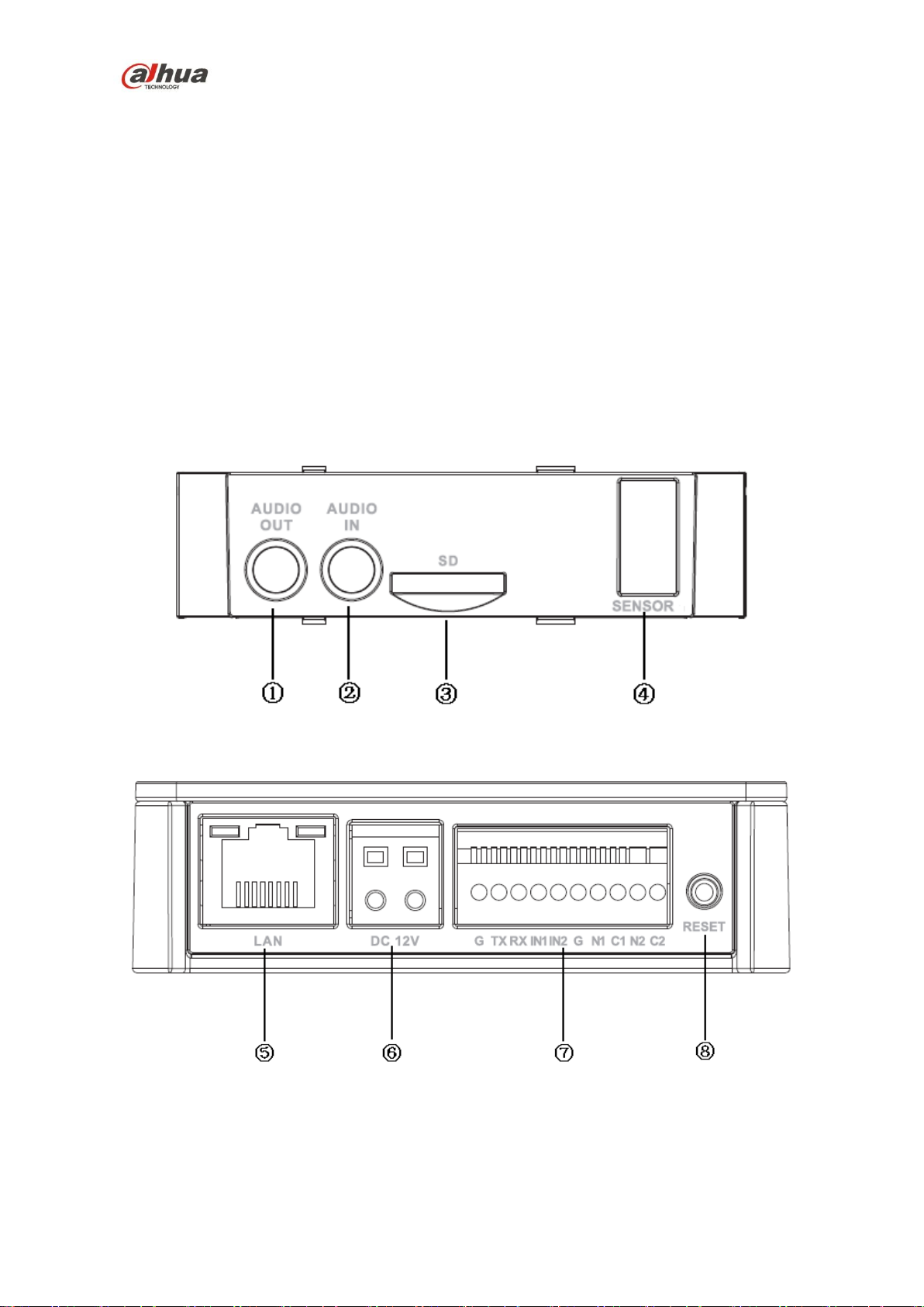
1.1.1.1 Structure
The following figures show the ports of device.
Figure 1-1 Ports of the device (1)
Figure 1-2 Ports of the device (2)
The following table shows the detailed information of ports function.
Page 7

Dahua HD Pinhole Network Camera Quick Start Guide
2
No.
Port
Port name
connector
Function description
1
AUDIO
OUT
Audio output
port
RCA
Output audio signal to the speakers and other
devices.
2
AUDIO IN
Audio input
port
RCA
Input audio signal, receive analog audio signal
from pickup and other devices.
3
Micro SD
Card
Micro SD
Micro SD
Card slot
Micro SD card storage
4
SENSOR
Sensor port
Sensor
board
Connect front end Sensor board, get image
data.
5
LAN
Network port
Ethernet
port
Connect standard Ethernet cable
6
DC12V
Power input
port
-
Power port, input DC12 V or POE power
supply.
7
I/O
I/O port
-
Connect I/O port.
8
Reset
Button
Reset
-
It is used to restore factory default settings for
the device.
Note
Continuously press the button for over 5
seconds in the situation where the device is
working normally, then the system
configuration info can be restored to factory
default settings.
Port name
Cable port name
Function description
I/O port
G
GND
TX
232 sending port.
RX
232 receiving port.
IN1
Alarm input port1,receive on-off signal from
external alarm source.
IN2
Alarm input port 2,receive on-off signal from
external alarm source.
G
GND
N1
Alarm output port1
C1
N2
Alarm output port2
C2
Table 1-1 Description of port function
The following table shows more details about I/O port.
Table 1-2 Description of I/O Port
Page 8

Dahua HD Pinhole Network Camera Quick Start Guide
3
Dimension
Refer to the following figures for dimension information of different models for modular pinhole
camera. The unit is mm.
Figure 1-3 Dimension of model A
Figure 1-4 Dimension of model B
Figure 1-5 Dimension of model C
Page 9

Dahua HD Pinhole Network Camera Quick Start Guide
4
Refer to the following figure for the dimension of rear end for the three models described above.
Figure 1-6 Dimension of rear end
1.1.2 Structure and dimension of All-in-one Pinhole Network Camera
The following figure shows the dimension of device.
Figure 1-7 Dimension of device
Page 10

Dahua HD Pinhole Network Camera Quick Start Guide
5
No.
Name
Function
1
Lens
Receive the optical signal from the environment.
2
Back cover
- 3 Binding wire
It is used to fix the cable.
4
Bracket
It is used to fix the camera.
5
Bracket adjusting screw
It is used to adjust the camera angle.
6
Front cover
-
7
Network port
Connect to standard Ethernet cable.
8
Power input port
Power port, input DC 12V。
The following figure shows the structure of device.
Figure 1-8 Structure of device
The following table shows more details about each component.
Table 1-3 Description of components
1.2 Bidirectional Talk
Note
This function is only supported by HD modular pinhole network camera.
The on-site listening operation is null during the bidirectional talk process.
To set up the bidirectional talk function, do the following:
1. Connect the MIC to the audio input port of the device and PC respectively. Then connect the
earphone to the audio output port of the device and PC respectively.
2. Login the Web and then click the Talk button to enable the bidirectional talk function, the
button becomes orange. Click Talk button again to close the bidirectional talk function.
3. Speak via the MIC at the device end or PC end, and you can receive the audio via the
earphone at the device end or PC end.
Page 11

Dahua HD Pinhole Network Camera Quick Start Guide
6
Note
The on-site listening operation is null during the bidirectional talk process.
1.3 Alarm Setup
Note
This function is only supported by some models of HD modular pinhole network camera.
The following figure shows the Alarm setup screen.
Figure 1-9 Alarm setup screen
To set up the Alarm input and output, do the following:
1. Connect alarm input device to the alarm input port of I/O cable.
2. Connect alarm output device to the alarm output port of I/O cable, alarm output port can only
be connected to NO alarm device.
3. Open the WEB, and then configure the alarm input and output in Alarm. Alarm input on WEB
corresponds to the Alarm input of I/O cable. Because the alarm input device will generate
high or low level signal when there is alarm, the configurations are corresponding NO and
NC inputs.
4. Set the WEB alarm output. The alarm output corresponds to the alarm output of I/O cable.
Page 12

Dahua HD Pinhole Network Camera Quick Start Guide
7
2 Device Installation
Note
All the installation figures below are for reference only due to the different models and
appearances. Please refer to the actual devices for exact details.
2.1 Installation of HD Modular Pinhole Network Camera
This product is a kind of separate device, and both the front end and the rear end of the device
have to be installed respectively. For front end, there are two types that are square and round,
and the square front end type has two installation ways.
Note
Please make sure the installation surface can support at least the 3X weight of the total weight of
the camera and the bracket.
The following figure shows the installation of round and square rear end:
Figure 2-1 Installation of round and square rear end
To install the round and square rear end, do the following:
1. Stick installation position map to designated surface where you will install the device.
2. Dig a hole according to position of hole on installation position map.
3. Open accessories bag, take out expansion bolt and insert it into the hole you just dug.
4. Open accessories bag, take out screws. Tighten the 3 screws to fix the device on the
installation surface where the bolts are located.
5. Put the camera body into the installation bracket directly.
6. Connect front-end lens to camera body by cable.
Page 13

Dahua HD Pinhole Network Camera Quick Start Guide
8
The followings figure shows the installation of round front end.
Figure 2-2 Installation of round front end
To install the round front end, do the following:
1. Take out the installation bracket from the accessories bag (with installation foam)
2. Tear off the film of the foam, and stick it on the surface to be installed.
3. Set the fixing ring on the installation bracket.
4. Put the round front end into the installation bracket and adjust the location.
5. Tighten the fixing ring.
There are two installation modes for square front end as follows:
Installation mode 1:
Figure 2-3 Installation mode 1 for square front end
Refer to the following installation steps:
1. Open the accessories bag and take out the fixing enclosure (with fixing foam).
2. Stick the fixing enclosure on the installation surface.
3. Embed the square front end into the fixing enclosure.
Page 14

Dahua HD Pinhole Network Camera Quick Start Guide
9
Installation Mode 2:
Figure 2-4 Installation mode 2 for square front end
Refer to the following installation steps:
1. Dig the holes for installation expansion bolts on the installation surface.
2. Take out the expansion bolts from the accessories bag and nail them into the holes you just
dug.
3. Open the accessories bag and take out the screws; tighten the three screws and fix the
device on the installation surface where the bolts are located.
4. Take out the decoration enclosure from the accessories bag, aim the device and press it hard
to install.
2.2 Installation of HD All-in-one Pinhole Network Camera
Note
The pinhole camera mainly adopts ceiling installation. The installation surface has to be thick
enough to sustain at least 3X weight of the camera.
Figure 2-5 Installation of device
Install the camera:
Use screws to fix the camera on the installation wall, as it is shown in Figure 2-1.
Page 15

Dahua HD Pinhole Network Camera Quick Start Guide
10
Location /angle adjustment:
1. Install the camera on the fixed wall together with the bracket.
The screw is installed in the middle hole, and then the camera can rotate.
The screw is installed in the left and right waist-shaped holes, and then the camera can
be adjusted rightward and leftward.
2. Loosen the bracket adjusting screw to adjust the camera angle.
Page 16

Dahua HD Pinhole Network Camera Quick Start Guide
11
3 Network Configuration
The IP address of all the cameras is the same when leaving factory (default IP 192.168.1.108).
To make the camera access to the network smoothly, please plan the available IP segment
reasonably according to the actual network environment.
3.1 Modify IP Address
The cameras which are accessed via wired network can acquire and modify the IP address
through “Quick Configuration Tool”. For the wireless network cameras, you need to connect to
the wired network to configure wireless parameters before use.
This section introduces the approach of modifying IP address via “Quick Configuration Tool”. You
can also modify the IP address in the network parameters of the WEB interface. Please refer to
the document WEB Operation Manual in the disk for more details.
Note
The camera can be configured only when the IP addresses of the camera and the computer are
in the same network segment.
To modify IP address, do the following:
1. Double-click the “ConfigTools.exe” and open the “Quick Configuration Tool”.
2. Double-click the device that needs to be configured.
The system will pop out the Login dialog box. See Figure 3-1 for more details.
3. Enter the IP address, username, password and port number of the camera, and then click
OK.
Note
The default username and password is admin and admin respectively, and the default port
is 37777.
Figure 3-1 Login
Page 17

Dahua HD Pinhole Network Camera Quick Start Guide
12
4. Modify the camera IP address on the Net interface, and then click Save to finish modification.
See Figure 3-2 for more details.
Figure 3-2 Network parameters
3.2 Login WEB Interface
Note
Different devices might have different WEB interfaces, the figures in this document are just for
reference, please refer to the document WEB Operation Manual in the disk and the actual
interface for more details.
To login WEB interface, do the following:
1. Open IE and input the modified camera IP address in the address bar, and then press Enter
key. The login interface shows. See Figure 3-3 for more details.
Figure 3-3 WEB Login
2. Input your username and password (Default username is admin and password is admin
respectively), click Login.
Page 18

Dahua HD Pinhole Network Camera Quick Start Guide
13
Note
The default username and password is admin and admin respectively, please modify the
administrator password as soon as possible after you successfully logged in.
3. Install controls according to the system prompt. See Figure 3-4 for the WEB main interface.
Figure 3-4 WEB main interface
Note
This quick start guide is for reference only. Minor differences might be found in user interface.
All the designs and software are subject to change without prior written notice.
If there is any uncertainty or controversy, please refer to our final explanation.
Please visit our website or contact your local service engineer for more information.
Dahua Vision Technology Co., Ltd.
Address: No.1199 Bin’an Road, Binjiang District, Hangzhou, PRC.
Postcode: 310053
Tel: +86-571-87688883
Fax: +86-571-87688815
Email: overseas@dahuatech.com
Website: www.dahuasecurity.com
 Loading...