

Dahua HDCVI Standalone DVR Quick Start Manual

Standalone DVR Quick Start Guide
Version 1.0.0

i
Table of Contents
1 Hardware Installation and Connection..........................................................................1
1.1 Check Unpacked DVR ..........................................................................................1
1.2 About Front Panel and Rear Panel.....................................................................1
1.3 After Remove the Chassis....................................................................................1
1.4 HDD Installation .....................................................................................................1
1.5 Rack Installation..................................................................................................... 2
1.6 Front Panel ............................................................................................................. 2
1.7 Rear Panel ..............................................................................................................3
1.8 Connection Sample ...............................................................................................3
1.9 Alarm Input and Output Connection ...................................................................4
1.9.1 Alarm Input and Output Details ......................................................... 4
1.9.2 Alarm Input Port ................................................................................ 5
1.9.3 Alarm Output Port.............................................................................. 5
2 Overview of Navigation and Controls............................................................................7
2.1 Boot up & Shut Down............................................................................................7
2.1.1 Boot up.............................................................................................. 7
2.1.2 Shut Down......................................................................................... 7
2.1.3 Auto Resume after Power Failure ..................................................... 7
2.1.4 Replace Button Battery .....................................................................7
2.2 Login ........................................................................................................................8
2.3 Preview....................................................................................................................9
2.4 Manual Record.....................................................................................................11
2.4.1 Record Operation............................................................................ 11
2.4.2 Snapshot Operation ........................................................................ 11
2.5 Search & Playback ..............................................................................................12
2.5.1 Smart Search .................................................................................. 16
2.5.2 Accurate playback by time .............................................................. 17
2.5.3 Mark Playback................................................................................. 18

ii
2.6 Schedule ............................................................................................................... 19
2.6.1 Quick Setup..................................................................................... 22
2.6.2 Redundancy .................................................................................... 23
2.7 Snapshot ...............................................................................................................23
2.7.1 Schedule Snapshot ......................................................................... 23
2.7.2 Trigger Snapshot............................................................................. 25
2.7.3 Priority ............................................................................................. 26
2.7.4 Image FTP ...................................................................................... 26
2.8 Network ................................................................................................................. 27
2.9 Pan/Tilt/Zoom .......................................................................................................29
2.9.1 PTZ Setup ....................................................................................... 29
2.9.2 PTZ Operation................................................................................. 30
3 Web Operation................................................................................................................32
3.1 Network Connection ............................................................................................32
3.2 Login ......................................................................................................................32
3.3 Main Window ........................................................................................................33
3.3.1 LAN Login ....................................................................................... 33
3.3.2 WAN Login ...................................................................................... 33
Appendix Toxic or Hazardous Materials or Elements .....................................................35

iii
Welcome
Thank you for purchasing our DVR!
This quick start guide will help you become familiar with our DVR in a very short time.
Before installation and operation, please read the following safeguard and warning carefully!
Important Safeguard and Warning
1.Electrical safety
All installation and operation here should conform to your local electrical safety codes.
We assume no liability or responsibility for all the fires or electrical shock caused by improper
handling or installation.
2.Transportation security
Heavy stress, violent vibration or water splash are not allowed during transportation, storage and
installation.
3.Installation
Keep upwards. Handle with care.
Do not apply power to the DVR before completing installation.
Do not place objects on the DVR.
4.Qualified engineers needed
All the examination and repair work should be done by the qualified service engineers.
We are not liable for any problems caused by unauthorized modifications or attempted repair.
5.Environment
The DVR should be installed in a cool, dry place away from direct sunlight, inflammable,
explosive substances and etc.
6. Accessories
Be sure to use all the accessories recommended by manufacturer.
Before installation, please open the package and check all the components are included:
Contact your local retailer ASAP if something is missing in your package.
7. Lithium battery
Improper battery use may result in fire, explosion, or personal injury!
When replace the battery, please make sure you are using the same model!

1
1 Hardware Installation and Connection
Note: All the installation and operations here should conform to your local
electric safety rules.
1.1 Check Unpacked DVR
When you receive the DVR from the forwarding agent, please check whether there is any visible
damage. The protective materials used for the package of the DVR can protect most accidental
clashes during transportation. Then you can open the box to check the accessories.
Please check the items in accordance with the list. (Remote control is optional). Finally you can
remove the protective film of the DVR.
Note
Remote control is not a standard accessory and it is not included in the accessory bag.
1.2 About Front Panel and Rear Panel
For detailed information of the function keys in the front panel and the ports in the rear panel,
please refer to the User’s Manual included in the resource CD.
The model label in the front panel is very important; please check according to your purchase
order.
The label in the rear panel is very important too. Usually we need you to represent the serial
number when we provide the service after sales.
1.3 After Remove the Chassis
Please check the data cable, power cable, COM cable and main boar cable connection is secure
or not.
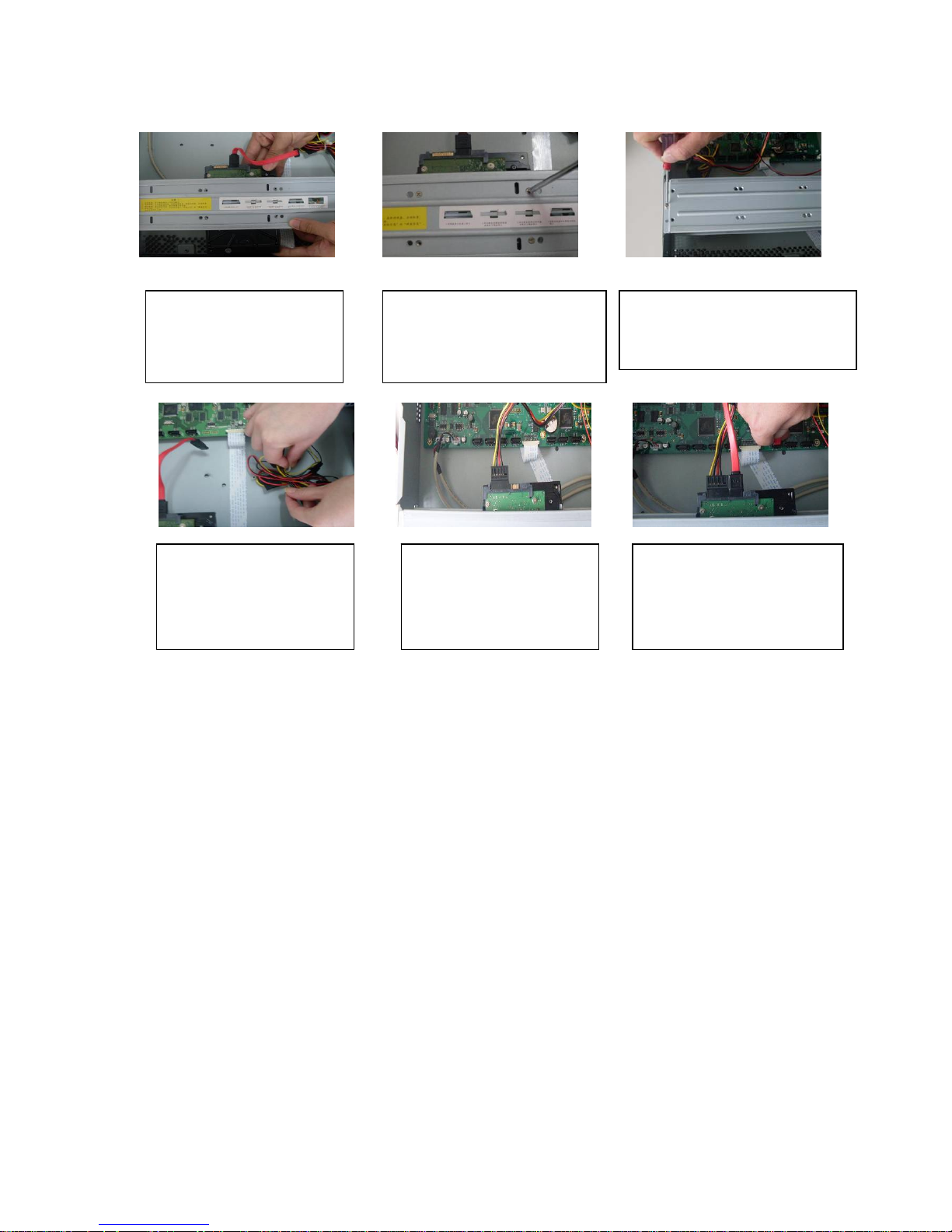
1.4 HDD Installation
Please note the following contents are based on our 2U series product. For detailed
operation instruction of other series products, please refer to the User’s Manual included
in the resources CD.
You can refer to the User’s Manual for recommended HDD brand. Please follow the instructions
below to install hard disk. This series DVR max supports 8 SATA HDDs. Please use HDD of
7200rpm or higher.
All the figurers listed below are for reference only. Slight difference may be found on the front or
rear panel.
2. Remove the HDD upper
bracket
3. Now you can see the bottom
bracket
1. Loosen the screws of the
u
pp
er cover.
2
Important
z You can connect the HDD data cable and the power cable first and then fix the HDD in the
device.
z Please pay attention to the front cover. It adopts the vertical sliding design. You need to
push the clip first and then put down.
1.5 Rack Installation
Please note this installation mode is for 1.5U/2U series product.
Please follow the steps listed below.
z Use twelve screws to fix the unit
z Please make sure the indoor temperature is below 35℃ (95°f).
z Please make sure there is 15cm (6 inches) space around the device to guarantee sound
ventilation.
z Please install from the bottom to the top.
z If there are more accessories connected in the rack, please take precaution measures in
case the rack power is overload.
1.6 Front Panel
For detailed operation instruction, please refer to the User’s Manual included in the
resources CD.
4. Line up the HDD to the
four holes of the HDD
bracket.
5. Use screws to fix HDD.
6. Install the upper bracket and then
Use screws to fix HDD in the
bracket.
7. Unfasten the HDD power
cable.
9. Use the special data cable to
connect the HDD and the SATA
port. Close the chassis and fix
the screws to secure firmly.
8. Insert the HDD power
cable.
3
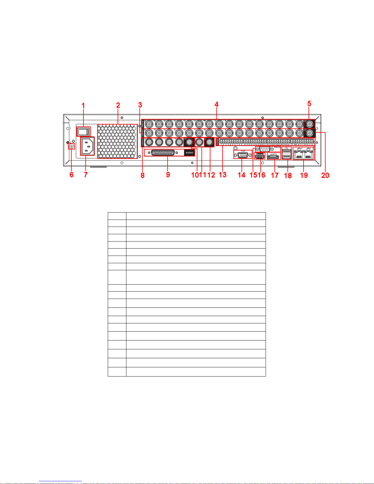
1.7 Rear Panel
Please note the following contents are based on our 2U 960H series product. For detailed
operation instruction of other series products, please refer to the User’s Manual included
in the resources CD.
This series DVR rear panel is shown as below. See Figure 1-1.
Figure 1-1
Please refer to the following sheet for detailed information.
1 Power button
2 Fan
3 Loop video output
4 Video input
5 Video output
6 Grounding hole
7 Power input port
8 Audio input port
9 DB25 port (the 5th to the 16th-channel audio
input port)
10 Audio output
11 Bidirectional talk input port
12 Bidirectional talk output port
13 Alarm input/alarm output/RS485 port
14 Video VGA output
15 RS-232 port
16 HDMI port
17 eSATA port
18 USB port
19 Network port
20 Video SPOT output
When connect the Ethernet port, please use crossover cable to connect the PC and use the
straight cable to connect to the switcher or router.
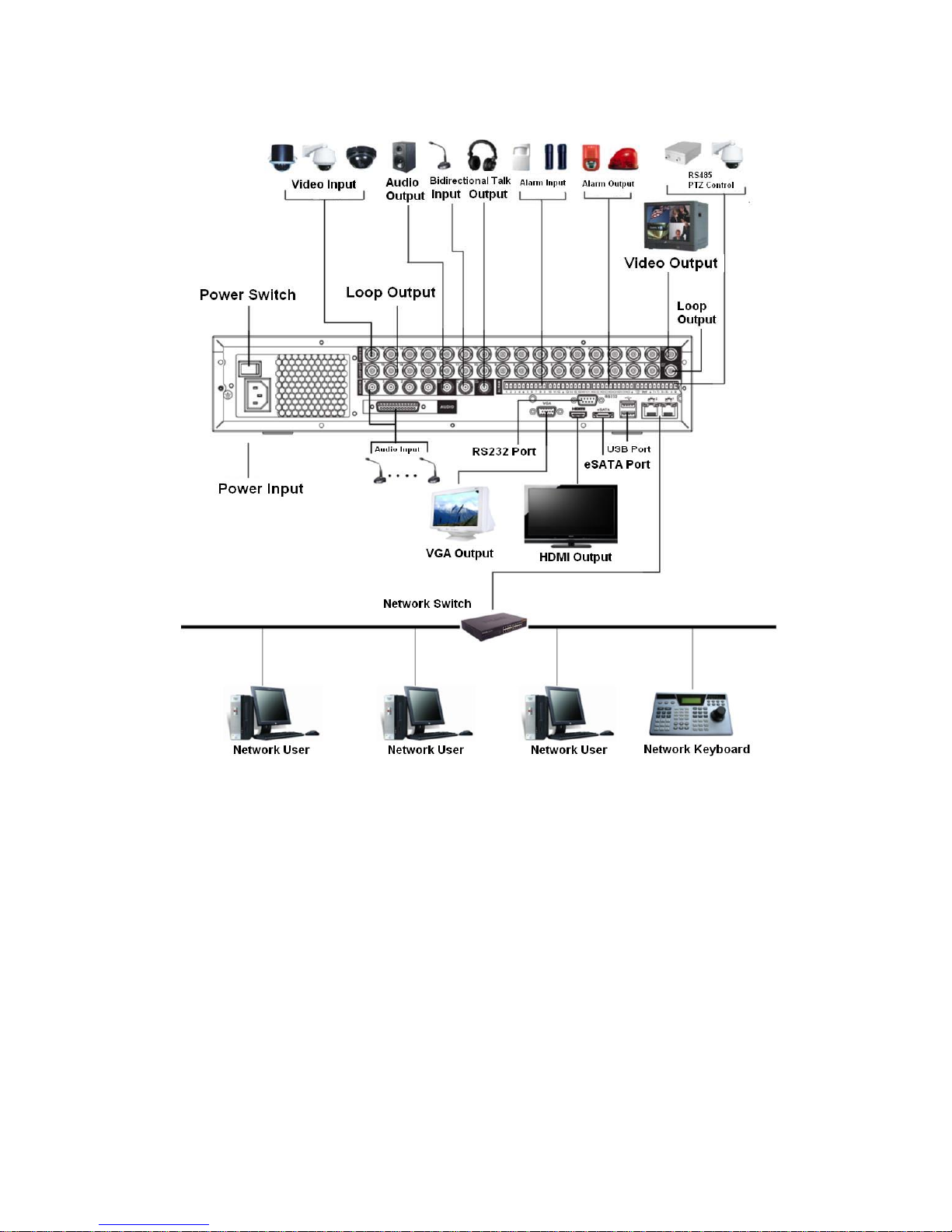
1.8 Connection Sample
Please note the following contents are based on our 2U 960H series product. For detailed
operation instruction of other series products, please refer to the User’s Manual included
in the resources CD.
4
Please refer to Figure 1-2 for connection sample.
The following figure is based on the 16-channel series product.
Figure 1-2
1.9 Alarm Input and Output Connection
Important
Please refer to the specifications for the alarm input and output channel amount. Do not
merely count the alarm input and out channel amount according to the ports on the rear
panel.
Please note the following contents are based on our 2U series product. For detailed
operation instruction of other series products, please refer to the User’s Manual included
in the resources CD.
There are two alarm input types for you to select: normal open (NO) and normal close (NC).
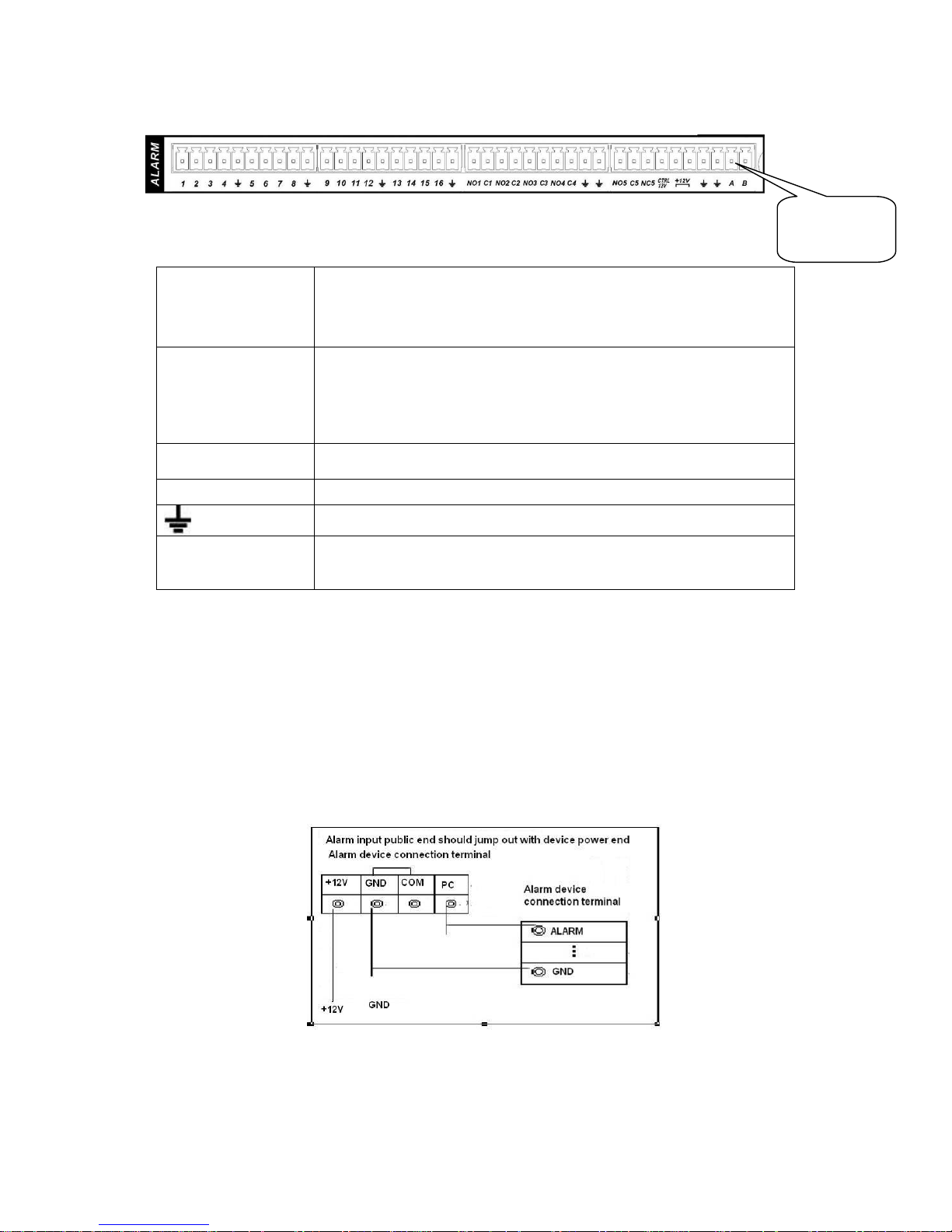
1.9.1 Alarm Input and Output Details
You can refer to the following sheet X for alarm input and output information.
Important
The general 2U series product interface is shown as in
5
Figure 1-3.
Figure 1-3
You can refer to the following sheet for alarm input and output information.
1,2,3,4,5,
6,7,8,9,10,
11,12,13,14,
15,16
ALARM 1 to ALARM 16. The alarm becomes active in low voltage.
NO1 C1,
NO2 C2,
NO3 C3,
NO4 C4,
NO5 C5 NC5
The first four are four groups of normal open activation output
(on/off button)
NO5 C5 NC5 is a group of NO/NC activation output (on/off button)
CTRL 12V Control power output. The power output is off when the alarm is
canceled.
+12V It is rated power output.
Earth cable.
485 A/B 485 communication port. They are used to control devices such as
PTZ. Please parallel connect 120TΩ between A/B cables if there are
too many PTZ decoders.
1.9.2 Alarm Input Port
Please refer to the following sheet for more information.
z Normal open or Normal close type.
z Please parallel connect COM end and GND end of the alarm detector (Provide external
power to the alarm detector).
z Use the controllable +12V power to reset the smoke sensor remotely.
z Please parallel connect the Ground of the DVR and the ground of the alarm detector.
z Please connect the NC port of the alarm sensor to the DVR alarm input(ALARM)
z Use the same ground with that of DVR if you use external power to the alarm device.
Figure 1-4
1.9.3 Alarm Output Port
z Provide external power to external alarm device.
AB cable
connection

6
z For controllable +12V, it can be used to provide power to devices such as reset smoke
sensor.
z To avoid overloading, please read relay parameters sheet in the User’s Manual carefully.
z RS485 A/B cable is for the A/B cable of the PTZ decoder.

7
2 Overview of Navigation and Controls
Please note the following contents are based on our 16-channel 2U series product. For
detailed operation instruction of other series products, please refer to the User’s Manual
included in the resources CD.
Before operation, please make sure:
z You have properly installed HDD and all the cable connections.
z The provided input power and the device power are matched.
z Always use the stable current, if necessary UPS is a best alternative measure.
2.1 Boot up & Shut Down
2.1.1 Boot up
Please follow the steps listed below to boot up the device.
z Connect the device to the monitor and then connect a mouse.
z Connect power cable.
z Click the power button at the front or rear panel and then boot up the device. After device
booted up, the system is in multiple-channel display mode by default.
2.1.2 Shut Down
Note
z When you see corresponding dialogue box “System is shutting down…” Do not click power
on-off button directly.
z Do not unplug the power cable or click power on-off button to shutdown device directly when
device is running (especially when it is recording.)
There are three ways for you to log out.
z Main menu (RECOMMENDED): From Main Menu->Operation->Shutdown, click shutdown
button, you can see device shuts down.
z From power on-off button on the front panel or remote control. Press the power on-off button
on the DVR front panel or remote control for more than 3 seconds to shutdown the device.
z From power on-off button on the rear panel.
2.1.3 Auto Resume after Power Failure
The system can automatically backup video and resume previous working status after power
failure.
2.1.4 Replace Button Battery
Please make sure to use the same battery model if possible.
We recommend replace battery regularly (such as one-year) to guarantee system time
accuracy.
Note:
Before replacement, please save the system setup, otherwise, you may lose the data
completely!
8
2.2 Login
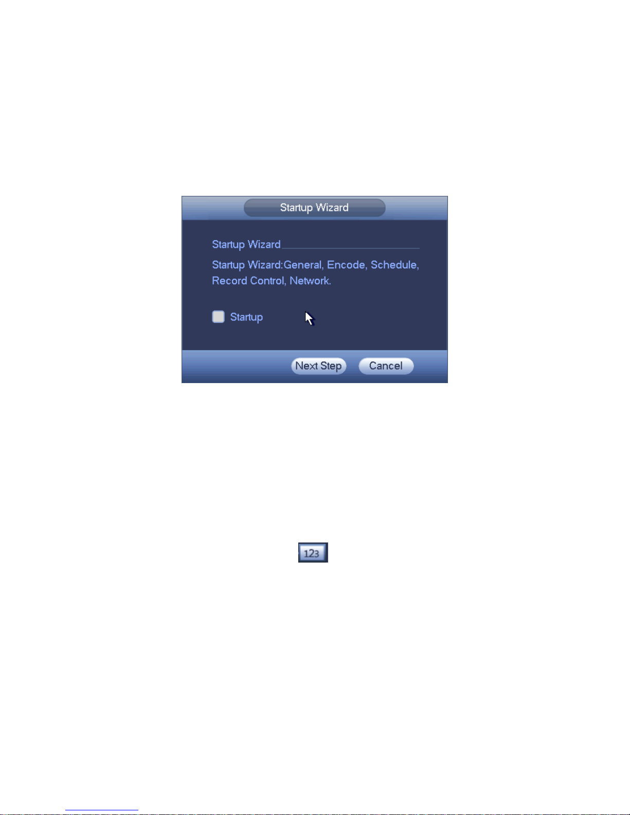
After system booted up, system pops up the startup wizard interface. See Figure 2-1.
Please refer to the user’s manual for detailed startup wizard operation information.
Tips
Check the box Startup button here, system goes to startup wizard again when it boots up the
next time.
Cancel the Startup button, system goes to the login interface directly when it boots up the next
time.
Figure 2-1
The system login interface is shown as in Figure 2-2.
System consists of four accounts:
z Username: admin. Password: admin. (administrator, local and network)
z Username: 888888. Password: 888888. (administrator, local only)
z Username: 666666. Password: 666666(Lower authority user who can only monitor, playback,
backup and etc.)
z Username: default. Password: default(hidden user)
You can use USB mouse, front panel, remote control (not included in the accessory bag) or
keyboard to input. About input method: Click
to switch between numeral, English
character (small/capitalized) and denotation.
Note:
For security reason, please modify password after you first login.
Continuous three times login failure will result in system alarm and six times login failure will
result in account lock!
 Loading...