

Page 1

HDCVR
i
HDCVI Series DVR User’s Manual
Version 1.0.0
Page 2

HDCVR
ii
Welcome
Thank you for purchasing our HDCVI DVR!
This user’s manual is designed to be a reference tool for the installation and operation of your
system.
Here you can find information about this series DVR features and functions, as well as a detailed
menu tree.
Before installation and operation please read the following safeguards and warnings carefully!
Page 3

HDCVR
iii
Important Safeguards and Warnings
1.Electrical safety
All installation and operation here should conform to your local electrical safety codes.
The product must be grounded to reduce the risk of electric shock.
We assume no liability or responsibility for all the fires or electrical shock caused by improper
handling or installation.
2.Transportation security
Heavy stress, violent vibration or water splash are not allowed during transportation, storage and
installation.
3.Installation
Keep upwards. Handle with care.
Do not apply power to the DVR before completing installation.
Do not place objects on the DVR.
4.Qualified engineers needed
All the examination and repair work should be done by the qualified service engineers.
We are not liable for any problems caused by unauthorized modifications or attempted repair.
5.Environment
The DVR should be installed in a cool, dry place away from direct sunlight, inflammable,
explosive substances and etc.
This series product shall be transported, storage and used in the specified environments.
6. Accessories
Be sure to use all the accessories recommended by manufacturer.
Before installation, please open the package and check all the components are included.
Contact your local retailer ASAP if something is broken in your package.
7. Lithium battery
Improper battery use may result in fire, explosion, or personal injury!
When replace the battery, please make sure you are using the same model!
Page 4

HDCVR
iv
MENU
1. FEATURES AND SPECIFICATIONS
..............................................................................................................................
- 6 -
1.1
OVERVIEW
...............................................................................................................................................................
- 6 -
1.2
FEATURES
...............................................................................................................................................................
- 6 -
2. OVERVIEW AND CONTROLS
.....................................................................................................................................
- 8 -
2
....................................................................................................................................................................................
- 8 -
2.1 HDD INSTALLATION
.....................................................................................................................................................
- 8 -
2.2 FRONT PANEL
.............................................................................................................................................................
- 9 -
2.2.1 CVR
.................................................................................................................................................................
- 9 -
2.3 REAR PANEL
.............................................................................................................................................................
- 10 -
2.3.1 CVR
.................................................................................................................................................................
- 10 -
2.4 CONNECTION SAMPLE
................................................................................................................................................
- 11 -
2.4.1 CVR
.................................................................................................................................................................
- 11 -
2.5
CONNECTING AUDIO INPUT & OUTPUT, BIDIRECTIONAL AUDIO
.........................................................................
- 12 -
2.5.1
Audio Input
....................................................................................................................................................
- 12 -
2.5.2
Audio Output
.................................................................................................................................................
- 12 -
2.6
RS485
..................................................................................................................................................................
- 13 -
3. OVERVIEW OF NAVIGATION AND CONTROLS
.......................................................................................................
- 14 -
3
..................................................................................................................................................................................
- 14 -
3.1 BOOT UP AND SHUTDOWN
..........................................................................................................................................
- 14 -
3.1.1
Boot up and Shutdown
..................................................................................................................................
- 14 -
3.1.2
Startup Wizard
...............................................................................................................................................
- 15 -
3.2
RIGHT-CLICK MENU
.............................................................................................................................................
- 16 -
3.2.1
Preview
..........................................................................................................................................................
- 16 -
3.2.2
PTZ Control
.....................................................................................................................................................
- 18 -
3.2.3
FigureColor
.....................................................................................................................................................
- 21 -
3.2.4
Playback
.........................................................................................................................................................
- 22 -
3.3
MAIN MENU
..........................................................................................................................................................
- 27 -
3.3.1 Main Menu
....................................................................................................................................................
- 27 -
3.3.2
Record
............................................................................................................................................................
- 28 -
3.3.3
System
............................................................................................................................................................
- 35 -
3.3.4
Information
....................................................................................................................................................
- 59 -
3.3.5
Advanced
.......................................................................................................................................................
- 64 -
3.3.6
Shut Down
......................................................................................................................................................
- 75 -
4. WEB OPERATION
....................................................................................................................................................
- 76 -
4
..................................................................................................................................................................................
- 76 -
4.1 NETWORK CONNECTION
..............................................................................................................................................
- 76 -
4.2
LOGIN
....................................................................................................................................................................
- 76 -
4.3 SYSTEM MENU
...........................................................................................................................................................
- 77 -
4.3.1
Live
.................................................................................................................................................................
- 77 -
4.3.2
Start dialogue button
.....................................................................................................................................
- 78 -
Page 5

HDCVR
v
4.3.3
Instant record button
.....................................................................................................................................
- 78 -
4.3.4
Local play button
...........................................................................................................................................
- 78 -
4.3.5
Window change
.............................................................................................................................................
- 79 -
4.3.6
PTZ control
.....................................................................................................................................................
- 79 -
4.3.7
Image
.............................................................................................................................................................
- 80 -
4.4
SETUP
...................................................................................................................................................................
- 81 -
4.4.1
Camera
..........................................................................................................................................................
- 81 -
4.4.2
Encode
............................................................................................................................................................
- 82 -
4.4.3
Network
.........................................................................................................................................................
- 86 -
4.4.4
Event
............................................................................................................................................................
- 100 -
4.4.5
Storage
.........................................................................................................................................................
- 104 -
4.4.6
Local Storage
...............................................................................................................................................
- 106 -
4.4.7
Record
..........................................................................................................................................................
- 106 -
4.4.8
Setting
..........................................................................................................................................................
- 107 -
4.5
INFORMATION
4.6 ALARM
..................................................................................................................................................................
- 119 -
4.7 LOG OUT
................................................................................................................................................................
- 120 -
4.8 UN-INSTALL WEB CONTROL
.......................................................................................................................................
- 121 -
5. PROFESSIONAL SURVEILLANCE SYSTEM
..............................................................................................................
- 122 -
6. FAQ
.......................................................................................................................................................................
- 123 -
5
................................................................................................................................................................................
- 123 -
6
................................................................................................................................................................................
- 123 -
6.1 FAQ
......................................................................................................................................................................
- 123 -
6.2
DAILY MAINTENANCE
..........................................................................................................................................
- 128 -
APPENDIX A HDD CAPACITY CALCULATION
................................................................................................................
- 129 -
APPENDIX B COMPATIBLE BACKUP DEVICE LIST
.........................................................................................................
- 130 -
COMPATIBLE USB DRIVE LIST
...........................................................................................................................................
- 130 -
COMPATIBLE SD CARD LIS
.....................................................................................................................................
- 131 -
APPENDIX C COMPATIBLE CD/DVD DEVICE LIST
.........................................................................................................
- 136 -
APPENDIX D COMPATIBLE DISPLAYER LIST
.................................................................................................................
- 137 -
APPENDIX E COMPATIBLE SWITCHER LIS
.....................................................................................................................
- 138 -
APPENDIX F COMPATIBLE WIRELESS MOUSE LIST
......................................................................................................
- 139 -
SPECIFICATIONS
............................................................................................................................................................
- 140 -
CVR
SERIES
.......................................................................................................................................................
- 140 -
APPENDIX H TOXIC OR HAZARDOUS MATERIALS OR ELEMENTS
...............................................................................
- 144 -
Page 6

HDCVR
- 6 -
1. FEATURES AND SPECIFICATIONS
1.1
Overview
This series product is an excellent digital monitor product designed for security field. It adopts embedded
Linux OS to maintain reliable operation. It is easy to use and can realize surveillance function after some
simple setups. It has various functions such as record, playback, monitor at the same time and can
guarantee audio video synchronization. This series product has advanced technology and strong
network data transmission function.
This series device adopts embedded design to achieve high security and reliability. It can work in the
local end, and at the same time, when connecting it to the professional surveillance software (PSS), it
can connect to security network to realize strong network and remote monitor function. It can realize HD
montiror without changing current cable layout
This series product can be widely used in various areas such as banking, telecommunication, electric
power, interrogation, transportation, intelligent resident zone, factory, warehouse, resources, and water
conservancy.
1.2 Features
This series product has the following features:
Real-time monitor
It has analog output port, VGA port and HDMI port. You can use monitor or displayer to realize
surveillance function.
System supports VGA/HDMI output at the same time.
Storage function
Special data format to guarantee data security and can avoid vicious data modification.
Compression format
Support multiple-channel audio and video. An independent hardware decodes the audio and video
signal from each channel to maintain video and audio synchronization.
Backup function
Support backup operation via USB port (such as flash disk, portable HDD, burner).
Client-end user can download the file to local HDD to backup via network.
Record playback function
Support each channel real-time record independently, and at the same time it can support search,
forward play, network monitor, record search, download and etc.
Page 7

HDCVR
- 7 -
Support various playback modes: slow play, fast play, backward play and frame by frame play.
Support time title overlay so that you can view event accurate occurred time
Support specified zone enlargement.
Network operation
Support network remote real-time monitor, remote record search and remote PTZ control.
Alarm activation function
Several relay alarm outputs to realize alarm activation and on-site light control.
The alarm input port and output has the protection circuit to guarantee device safety.
Communication port
RS485 port can realize alarm input and PTZ control.
RS232 port can connect to keyboard to realize central control, and can also connect to PC COM to
upgrade system and realize maintenance, and matrix control.
Standard Ethernet port can realize network access function.
PTZ control
Support PTZ decoder via RS485.
Support various decode protocols to allow the PTZ to control the speed dome.
Intelligent operation
Mouse operation function
In the menu, support copy and paste setup function
UPnP
It is to establish the mapping relationship between the LAN and the WAN via the UPnP protocol.
Slight function differences may be found due to different series.
Page 8
HDCVR
- 8 -
2. Overview and Controls
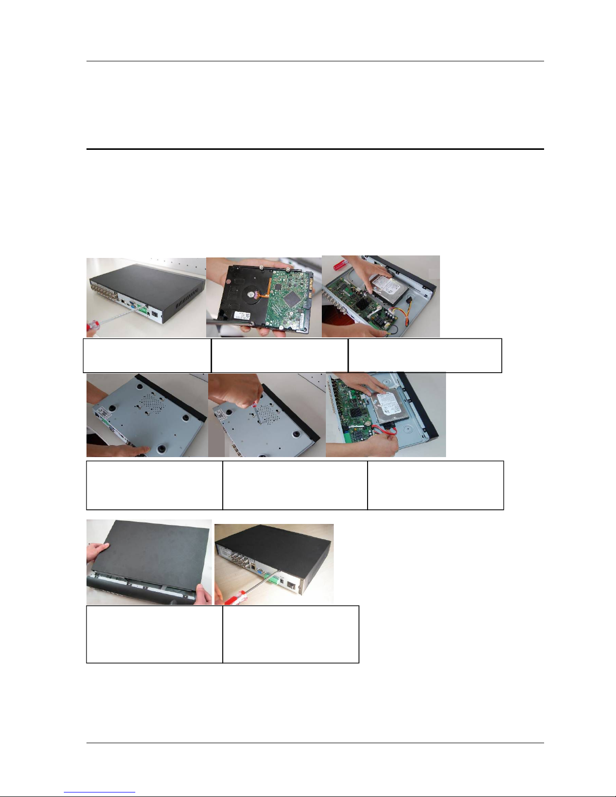
2.1 HDD Installation
This series DVR has only one SATA HDD. Please use HDD of 7200rpm or higher.
You can refer to the User’s Manual for recommended HDD brand.
Please follow the instructions below to install hard disk.
Note:
You can connect the HDD data cable and the power cable first and then fix the HDD in the device.
Please pay attention to the front cover. It adopts the vertical sliding design. You need to push the clip first
and then put down.
1. Loosen the screws of the
upper cover and side panel.
2. Fix four screws in the HDD
(Turn just three rounds).
3. Place the HDD in accordance with
the four holes in the bottom.
4. Turn the device upside down
and then turn the screws in
firmly.
5.Fix the HDD firmly.
6. Connect the HDD cable and
power cable.
7. Put the cover in accordance
with the clip and then place the
upper cover back.
8. Secure the screws in the
rear panel and the side panel.
Page 9

HDCVR
- 9 -
2.2 Front Panel
2.2.1CVR
Figure2- 1
Please refer to the following sheet for front panel button information.
Name
Icon
Function
Power button
Power button, press this button for three seconds to boot up or
shut down DVR.
Up
Down
、
Activate current control, modify setup, and then move up and
down.
Increase/decrease numeral.
Assistant function such as PTZ menu.
Left
Right
Shift current activated control,
When playback, click these buttons to control playback bar..
ESC
ESC
Go to previous menu, or cancel current operation.
When playback, click it to restore real-time monitor mode.
Enter
ENT
ER
Confirm current operation
Go to default button
Go to menu
Assistant
Fn
One-window monitor mode, click this button to display assistant
Backspace function: in numeral control or text control, press it
for 1.5seconds to delete the previous character before the
In motion detection setup, working with Fn and direction keys to
realize setup.
In text mode, click it to switch between numeral, English
character(small/capitalized) and etc.
Realize other special functions.
USB port
To connect USB storage device, USB mouse.
Page 10

HDCVR
- 10 -
Network
abnormal
indication
light
Net
Network error occurs or there is no network connection, the
light becomes red to alert you.
HDD
abnormal
indication
light
HD
D
HDD error occurs or HDD capacity is below specified threshold
value, the light becomes red to alert you.
IR Receiver
IR
It is to receive the signal from the remote control.
2.3 Rear Panel
2.3.1CVR
Here we take the 4-channel series product rear panel as an
example
Figure2- 2 CVR
The 8-channel series rear panel is shown as below
Figure2- 3 CVR
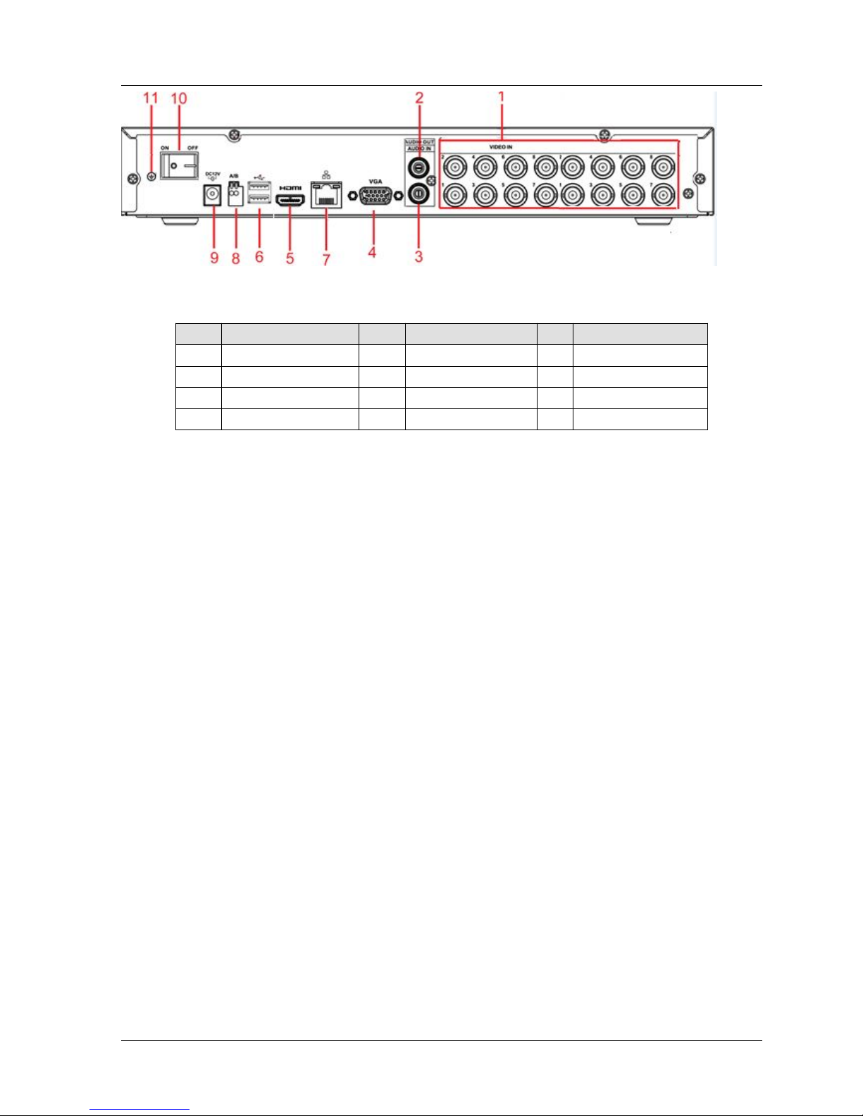
The 16-channel series rear panel is shown as below
Page 11
HDCVR
- 11 -
Figure2- 4 CVR
Please refer to the following sheet for detailed information.
SN
Name
SN
Name
SN
Name
1
Video input
2
Audio output
3
Audio input
4
Video VGA output
5
HDMI port
6
USB port
7
Network port
8
RS-485 input port
9
Power socket
10
On/Off button
11
GND port
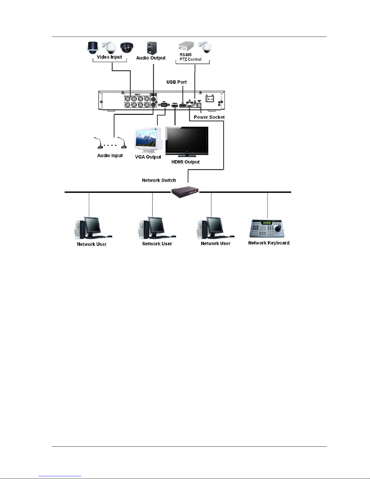
2.4 Connection Sample
2.4.1CVR
Please note the following contents are based on our 1U 720P series product. For detailed operation
instruction of other series products, please refer to the User’s Manual included in the resources CD.
The following figure is based on the 4-channel series product.
Page 12
HDCVR
- 12 -
Figure 2- 4
2.5 Connecting Audio Input & Output, Bidirectional Audio
2.5.1
Audio Input
These series products audio input port adopt BNC port.
Due to high impedance of audio input, please use active sound pick-up.
Audio transmission is similar to video transmission. Try to avoid interference, dry joint, loose contact
andit shall be away from high tension current.
2.5.2 Audio Output
The audio output signal parameter is usually over 200mv 1KΩ (BNC or RCA). It can directly connect to
low impedance earphone, active sound box or amplifier-drive audio output device.
If the sound box and the pick-up cannot be separated spatially, it is easy to arouse squeaking. In this
case you can adopt the following measures:
Use better sound pick-up with better directing property
Reduce the volume of the sound box.
Page 13

HDCVR
- 13 -
Using more sound-absorbing materials in decoration can reduce voice echo and improve
acousticsEnvironment.
Adjust the layout to reduce happening of the squeaking.
2.6 RS485
When the DVR receives a camera control command, it transmits that command up the coaxial cable
to the
PTZ device. RS485 is a single-direction protocol; the PTZ device can’t return any data to the unit. To
enable
X28 9H 2 89 H2 8 9H X
Since RS485 is disabled by default for each camera, you must enable the PTZ settings first. This
series
DVRs support multiple protocols such as Pelco-D, Pelco-P.
To connect PTZ devices to the DVR:
1. Connect RS485 A,B on the DVR rear panel.
2. Connect the other end of the cable to the proper pins in the connector on the camera.
3. Please follow the instructions to configure a camera to enable each PTZ device on the DVR.
Page 14

HDCVR
- 14 -
3. Overview of Navigation and Controls
3.1 Boot up and Shutdown
3.1.1
Boot up and Shutdown
Boot up
Before the boot up, please make sure:
The rated input voltage matches the device power on-off button. Please make sure the power
wireconnection is OK. Then click the power on-off button.
Always use the stable current, if necessary UPS is a best alternative measure.Please follow the
steps listed below to boot up the device
Connect the device to the monitor and then connect a mouse.
Connect power cable
Click the power button at the front or rear panel and then boot up the device. After device booted
up,the system is in multiple-channel display mode by default.
Shutdown
Note
When you see corresponding dialogue box “System is shutting down…” Do not click power on-offbutton
directly.
Do not unplug the power cable or click power on-off button to shutdown device directly when
deviceis running (especially when it is recording.)
There are three ways for you to log out.
a)Main menu (RECOMMENDED)
From Main Menu->Shutdown, select shutdown from dropdown list.
Click OK button, you can see device shuts down.
b)From power on-off button on the front panel or remote control
Press the power on-off button on the DVR front panel or remote control for more than 3 seconds
toshutdown the device.
c)From power on-off button on the rear panel
Replace Button Battery
Please make sure to use the same battery model if possible.
We recommend replace battery regularly (such as one-year) to guarantee system time accuracy.
Page 15
HDCVR
- 15 -
Note:
Before replacement, please save the system setup, otherwise, you may lose the data
completely!
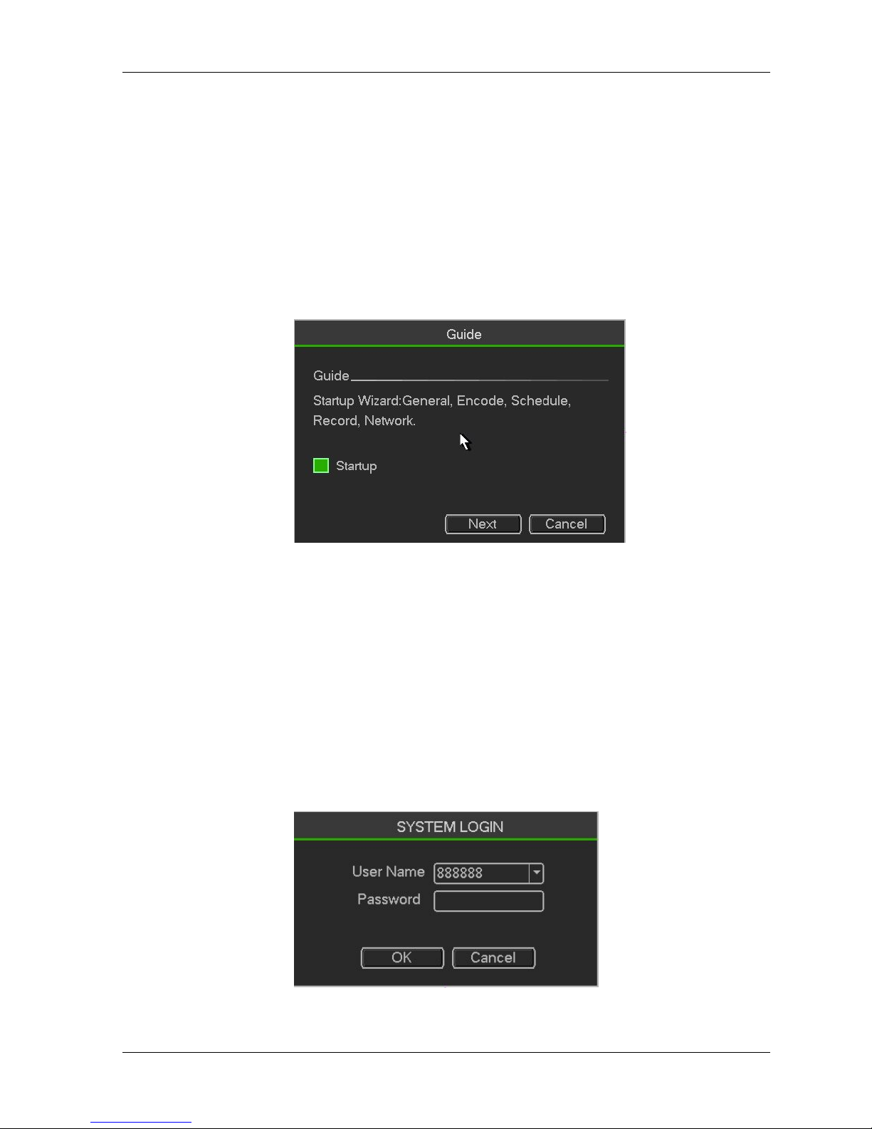
3.1.2 Startup Wizard
After device successfully booted up, it goes to startup wizard.
Click Cancel/Next button, you can see system goes to login interface.
Tips
Check the box Startup button here, system goes to startup wizard again when it boots up the next time.
Cancel the Startup button, system goes to the login interface directly when it boots up the next time.
Figure 3- 1
Click Cancel button or Next Step button, system goes to login interface. See Figure 3-2.
System consists of four accounts:
Username: admin. Password: NULL/admin. (administrator, local is NULL and network is admin)
Username: 888888. Password: NULL. (administrator, local only)
Username: 666666. Password: NULL(Lower authority user who can only monitor, playback,
backup and etc.)
Username: default. Password: default (hidden user). Hidden user “default” is for system interior
use only and can not be deleted. When there is no login user, hidden user “default” automatically
login. You can set some rights such as monitor for this user so that you can view some channel
view without login.
Figure 3- 2
Note:
Page 16
HDCVR
- 16 -
For security reason, please modify password after you first login.
Within 30 minutes, three times login failure will result in system alarm and five times login failure
willresult in account lock!
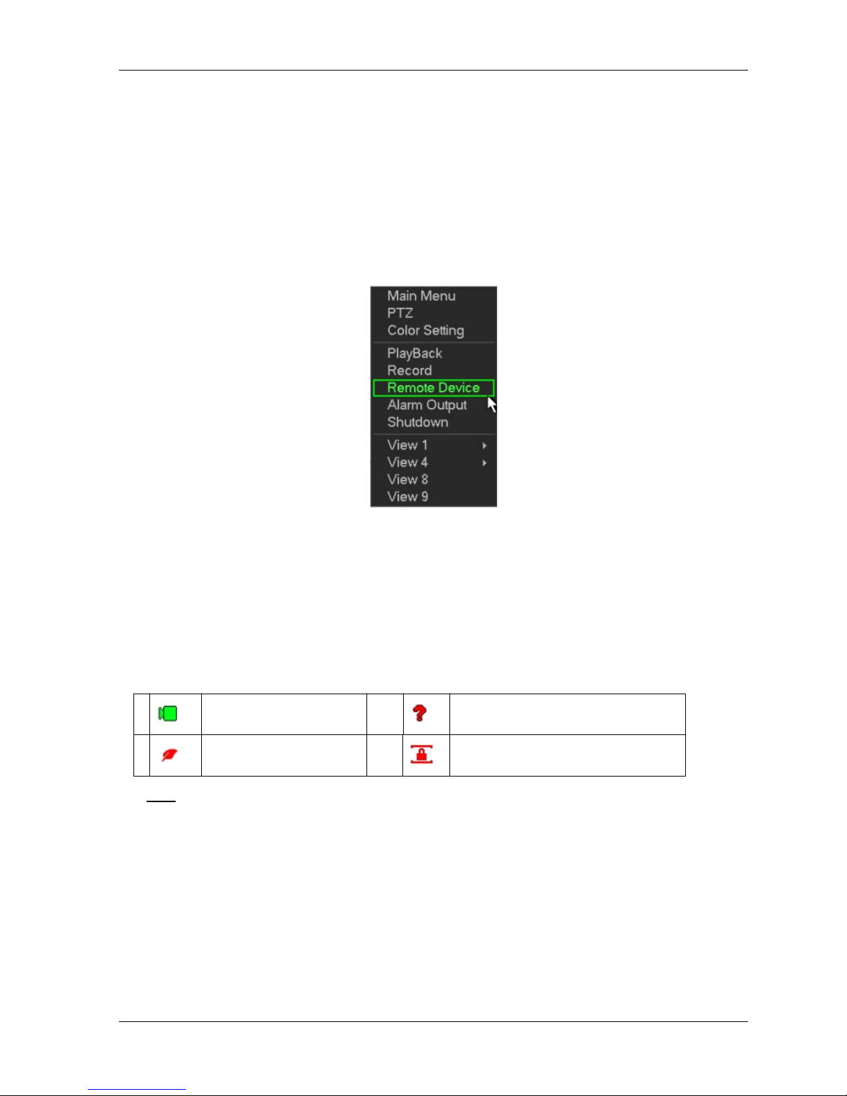
3.2 Right-Click Menu
On the preview interface, right click mouse, you can view menu interface shown as in Figure 3-3.
Tips
After you go to the corresponding interface, right click mouse to go back to the upper-level。
Figure 3- 3
Preview
After you logged in, the system is in live viewing mode by default. You can see system date, time and
channel name. If you want to change system date and time, you can refer to general settings (Main
Menu->Setting->System->General). If you want to modify the channel name, please refer to the display
settings (Main Menu->Setting->Camera->CAM Name)。
Tips
Preview drag: If you want to change position of channel 1 and channel 4 when you are previewing,
you can left click mouse in the channel 1 and then drag to channel 4, release mouse you can switch
channel 1 and channel 4 positions.
Use mouse middle button to control window split: You can use mouse middle button to switch
window split amount.
Preview Control
he preview control function has the following features.
Support preview playback.
1
Recording status
3
Video loss
2
Motion detection
4
Camera lock
Page 17
HDCVR
- 17 -
In the preview desktop, system can playback previous 5-60 minutes record of current channel.
Please go to the Main Menu->Setting->->System->General to set real-time playback time.
Support drag and play function. You can use your mouse to select any playback start time.
Support playback, pause and exit function.
Right now, system does not support slow playback and backward playback function.
Support digital zoom function.
Support real-time backup function.
You can follow the contents listed below for the operation instruction.
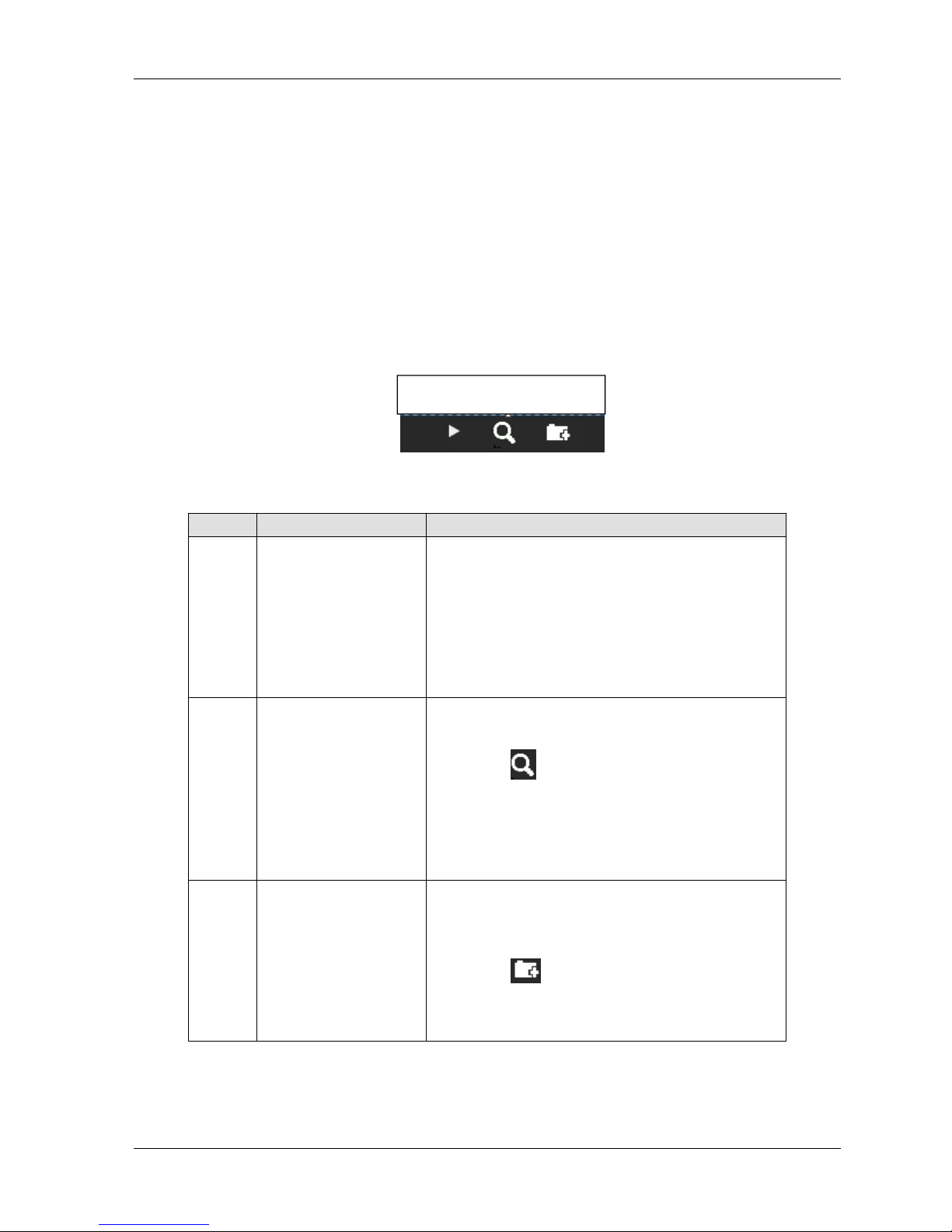
Preview control interface
Move you mouse to the top centre of the video of current channel, you can see system pops up the
preview control interface. If your mouse stays in this area for more than 6 seconds and has no operation,
the control bar automatically hides.
Figure 3- 4
You can refer to the following sheet for detailed information.
SN
Name
Function
1
Realtime playback
It is to playback the previous 5-60 minutes record of
current channel.
Pleasego to the Main
Menu->Setting->->System->General to set real-time
playback time.
System may pop up a dialogue box if there is no such
record in current channel.
2
Digital zoom
It is to zoom in specified zone of current channel. It
supports zoom in function of multiple-channel.
Clickbutton , the button is shown asDrag the
mouse or use the middle button to select a zone, you
can view.
Right click mouse to cancel zoom and go back to the
original interface.
3
Real-time backup
function
It is to backup the video of current channel to the
USB device. System can not backup the video of
multiple-channel at the same time.
Clickbutton
,
system begins recording. Click it
again, system stops recoridng. You can find the
record file on the flash disk.
playback control
The playback control has the following features.
1 2 3
Page 18
HDCVR
- 18 -
Support play, pause, and exit and drag function.
During the preview playback process, you can not see the channel title and record status of current
channel. It will display the channel title and the record status once you exit the preview playback.
During the preview playback, you can not switch the displayed channel or change current
window-display mode.
System closes preview control interface when you are switching split mode.
Please note the tour function has the higher priority than the preview playback. You can not control
the preview playback until the tour function ended.
PTZ Control
Please note the commend name is grey once device does not support this function.
The PTZ operation is only valid in one-window mode.
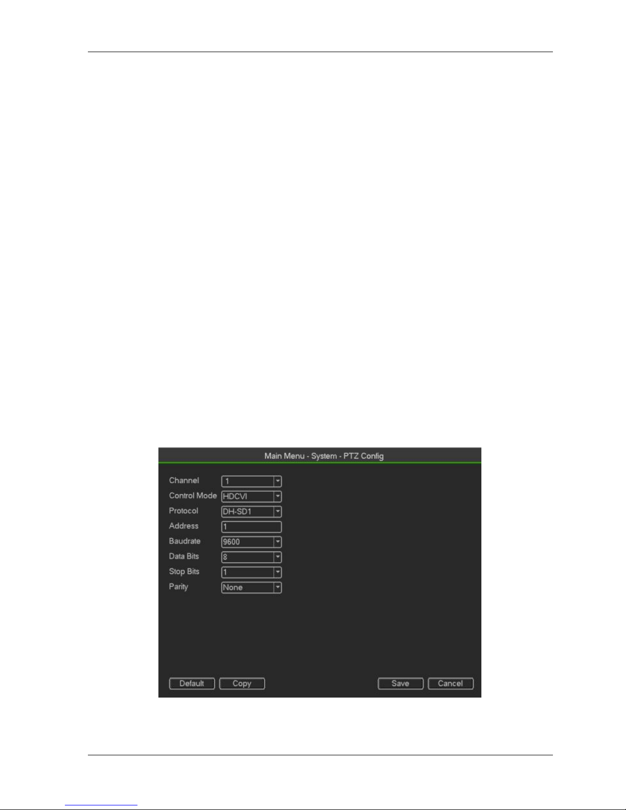
PTZ Setup
In the main menu, from Setting->System->PTZ, you can see the following interface. The pan/tilt/zoom setup
includes the following items. Please select channel first.
Protocol: Select corresponding PTZ protocol such as PELCOD.
Address: Input corresponding PTZ address.
Baud rate: Select baud rate.
Data bit: Select data bit. Default value is 8.
Stop bit: Select stop bit.Default value is 1.
Parity: There are three choices: none/odd/even. Default value is none.
Figure 3- 5
In one window display mode, right click mouse (click “Fn” Button in the front panel or click “Fn” key in the
Page 19

HDCVR
- 19 -
remote control).
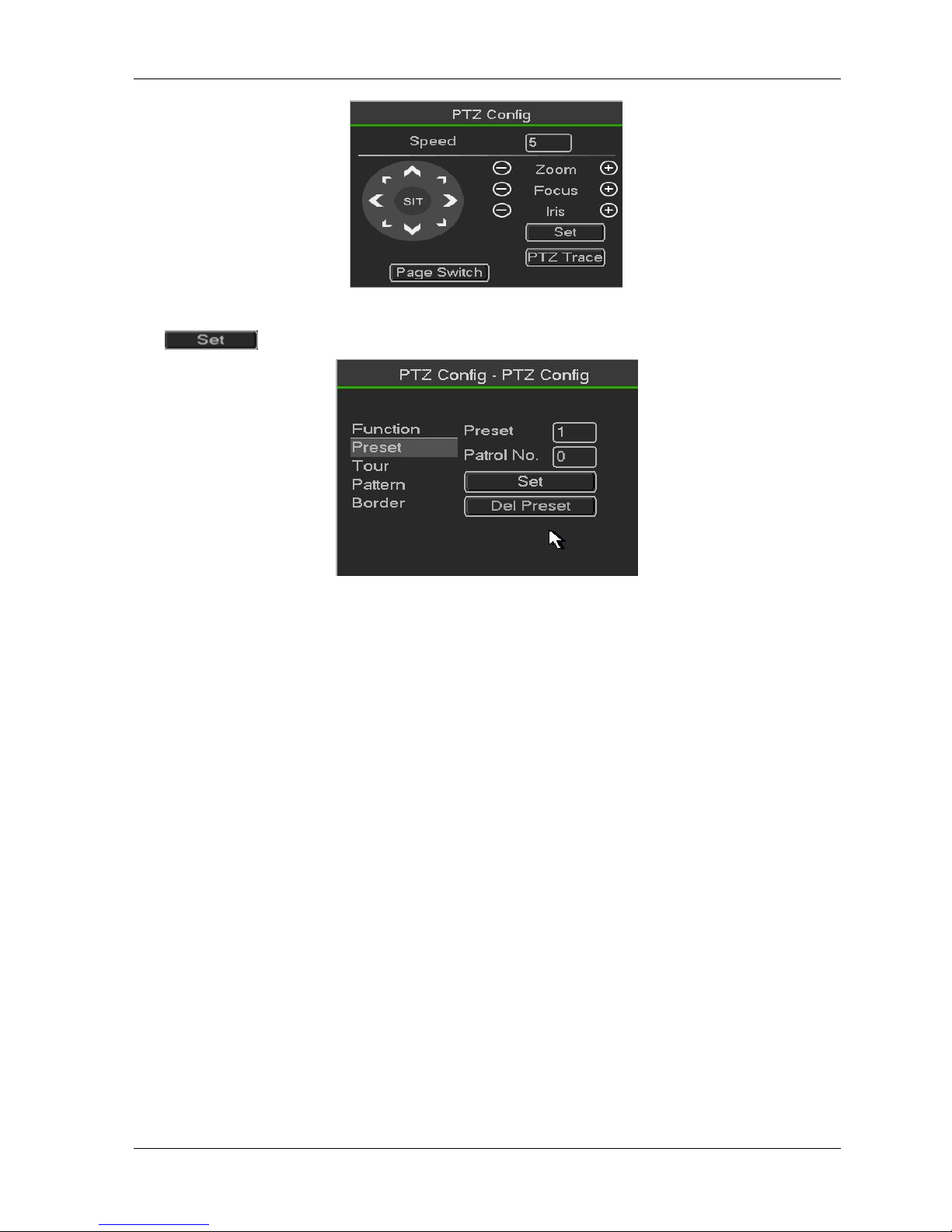
Click Pan/Tilt/Zoom, the interface is shown as below.
Here you can set the following items:
Step: value ranges from 1 to 8.Zoom.Focus .Iris
Figure 3- 6
PTZ set
Here you can control PTZ direction, speed, zoom, focus, iris, preset, tour, scan, pattern aux function,
light and wiper, rotation and etc
Speed is to control PTZ movement speed. The value ranges from 1 to 8.The speed 8 is faster than
speed 1. You can use the remote control to click the small keyboard to set.
You can click and of the zoom, focus and iris to zoom in/out, definition and brightness.
The PTZ rotation supports 8 directions. If you are using direction buttons on the front panel, there are
only four directions: up/down/left/right.
Here is a sheet for you reference.
Name
Function
key
function
Shortcut
key
Function
key
function
Shortcut
Key
Zoom
Near
►
Far
Focus
Near
Far
►
Iris
close
Open
In the middle of the eight direction arrows, there is a 3D intelligent positioning key. .
Please make sure your protocol supports this function and you need to use mouse to control.
Click this key, system goes back to the single screen mode. Drag the mouse in the screen to adjust
section size. The dragged zone supports 4X to 16X speeds. It can realize PTZ automatically. The
smaller zone you dragged, the higher the speed.
PTZ Function Setup
Page 20
HDCVR
- 20 -
Figure 3- 7
Click
,
you can go to the following interface to set preset, tour, pattern, and scan
Figure 3- 8
Preset Setup
click preset button and use eight direction arrows to adjust camera to the proper position..
Click Set button and then input preset number.
Click Set button to save current preset.
Tour Setup
click tour button.
Input tour value and preset No. Click Add preset button to add current preset to the tour.
Tips
Repeat the above steps to add more presets to the tour. Click Del preset button to remove it from the
tour. Please note some protocols do not support delete preset function.
Pattern Setup
click Pattern button and input pattern number.
Click Begin button to start direction operation. Or you can go to operate
zoom/focus/iris/direction operation.
click End button
Scan Setup
click Scan button.
Use direction buttons to set camera left limit and then click Left button.
Use direction buttons to set camera right limit and then click Right button. Now the scan setup process is
complete.
Page 21
HDCVR
- 21 -
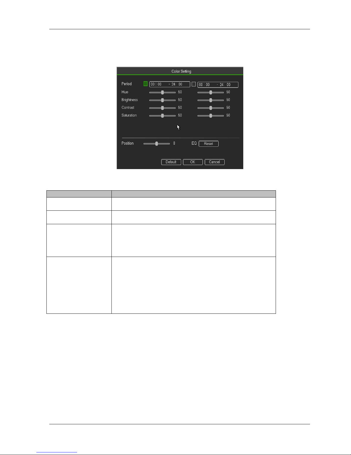
FigureColor
Here you can set hue, brightness, contrast, saturation, gain, white level, color mode and etc
。
Figure4- 1
Please refer to the following sheet for detailed information.
Item
Note
Period
There are two periods in one day. You can set different
sharpness, brightness, and contrast setup for different periods.
Effective Time
Check the box here to enable this function and then set period
time.
Contrast
The value here is to adjust the edge of the video. The value
ranges from 0 to 100. The larger the value is, the clear the
edge is and vice versa. Please note there is noise if the value
here is too high. The default value is 50 and the recommended
value ranges from 40 to 60.
Brightness
It is to adjust monitor window bright. The value ranges from 0
to 100. The default value is 50.
The larger the number, the bright the video is. When you input
the value here, the bright section and the dark section of the
video will be adjusted accordingly. You can use this function
when the whole video is too dark or too bright. Please note the
video may become hazy if the value is too high. The
recommended value ranges from 40 to 60.
Page 22
HDCVR
- 22 -
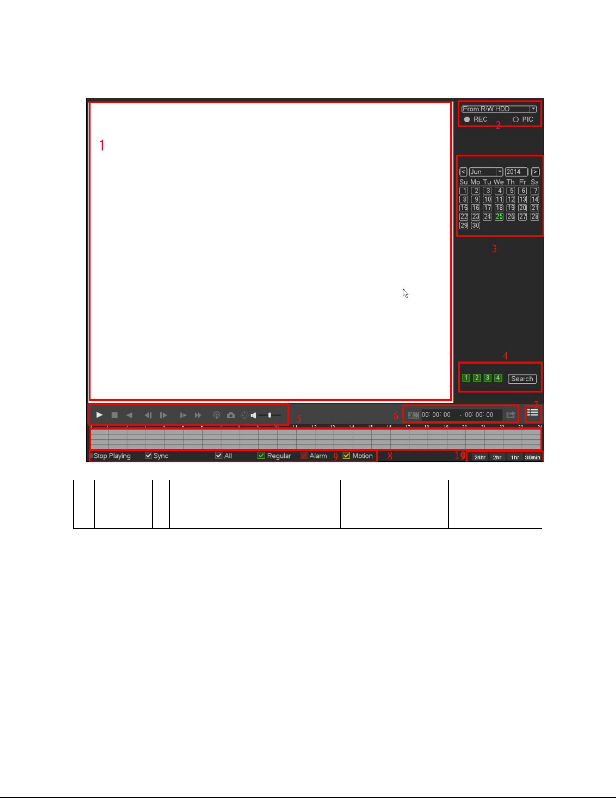
Playback
Figure 3- 9
Displaywindow
Here is to display the searched picture or file.
Support 1/4/8-window playback.
Searchtype
Here you can select to search the picture or the recorded file
”。
1
Displaywi
ndow
2
Searchtype
3
Calendar
4
Channelselection
5
Playback
control
6
Clip
7
Smartsearc
h
8
Time bar
9
Recordtype
10
Time bar
unit
Page 23

HDCVR
- 23 -
Record search
You can select to play from the read-write HDD, from peripheral device or from
redundancy HDD
Important
Redundancy HDD does not support picture backup function, but it
supports picture playback function. You can select to play from redundancy
HDD if there are pictures on the redundancy HDD.
Figure search
Before you select to play from the peripheral device, please connect the
corresponding peripheral device. You can view all record files of the root directory
of the peripheral device. Click the Browse button; you can select the file you want
Calendar
The blue highlighted date means there is picture or file. Otherwise, there is nopicture or file.
In any play mode, click the date you want to see, you can see the correspondingrecord file trace in the time
bar.
Channelselection
Playback mode:1/4/9. (It may vary due to different series.)
In 1-window playback mode: you can select 1-16 channels.
In 4-window playback mode: you can select 4 channels according to your
requirement.
In 9-window playback mode, you can switch between 1-8 and 9-16 channels.
The time bar will change once you modify the playback mode or the channel
Playback control
Figure 3- 10
►/
Play/Pause
There are three ways for you to begin playback.
The play button
Double click the valid period of the time bar.
Double click the item in the file list.
In slow play mode, click it to switch between play/pause.
■
Stop
Backward play
In normal play mode, left click the button, the file begins backward play.
Click it again to pause current play.
In backward play mode, click ►/ to restore normal play.
│/
│
In playback mode, click it to play the next or the previous section. You can
click continuously when you are watching the files from the same channel.
In normal play mode, when you pause current play, you can click│ and
│ to begin frame by frame playback.
In frame by frame playback mode, click ►/ to restore normal playback.
Page 24

HDCVR
- 24 -
►
Slow play
In playback mode, click it to realize various slow play modes such as slow
play 1, slow play 2, and etc.
Fast forward
In playback mode, click to realize various fast play modes such as fast
play 1,fast play 2 and etc.
Note: The actual play speed has relationship with the software version.
Smart search
The volume of the playback
Click the snapshot button in the full-screen mode, the system can snapshot
1 picture.
System supports custom snap picture saved path. Please connect the
peripheral device first, click snap button on the full-screen mode, you can
select or create path. Click Start button, the snapshot picture can be saved
to the specified path.
Mark button.
Please note this function is for some series product only. Please make sure
there is a mark button in the playback control pane.
You can refer to chapter 4.8.1.3 for detailed information.
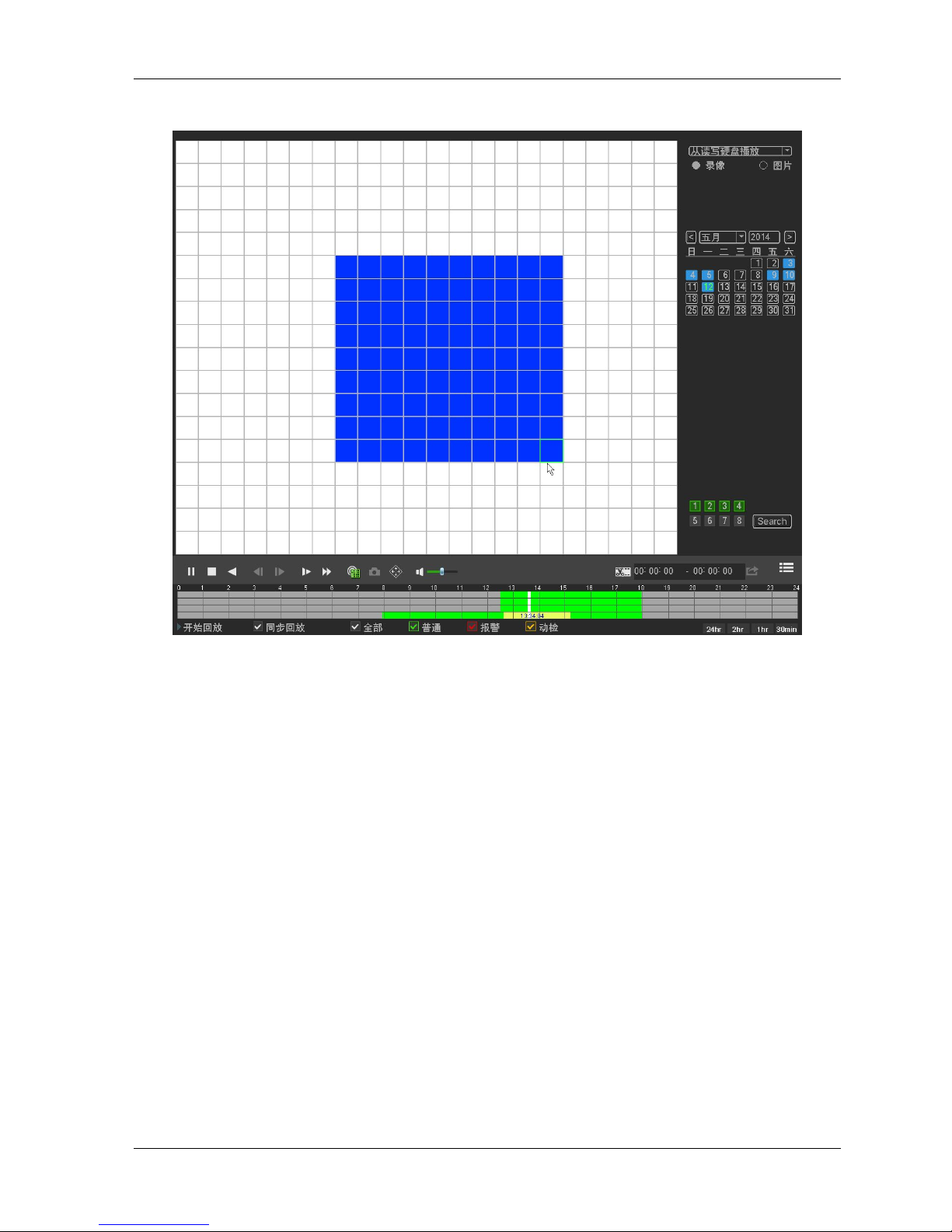
Smart Search
When system is playing, you can select a zone in the window to begin smartsearch. Click the motion
detect button to begin play.
Once the motion detect play has begun, click button again will terminatecurrent motion detect file play.
There is no motion detect zone by default.
If you select to play other file in the file list, system switches to motion detectplay of other file.
During the motion detect play process, you can not implement operations suchas change time bar, begin
backward playback or frame by frame playback.
Smart search step
During the multiple-channel playback mode, double click one channel and then click th
,
system
begins smart search.
System supports 396(22*18 PAL) and 330(22*15 NTSC) zones. Please left
click mouse to select smart search zones
Click the ,
you can go to the smart search playback. Click it again, system stops smart search
playback。
Important
System does not support motion detect zone setup during the full-screen mode.
During the multiple-channel playback, system stops playback of rest channels if you
implement one-channel smart search.
Page 25
HDCVR
- 25 -
Figure 3- 11
Clip
1,
Please play the file you want to edit and then click this button when you want to
edit. You can see the corresponding slide bars in the time bar of the corresponding
channel. You can adjust the slide bar or input the accurate time to set the file end
time.
2,After you set, you can click Clip button again to edit the second period. You can
see the slide bar restore its previous position.
3,Click Backup button after clip, you can save current contents in a new file.
4, You can clip for one channel or multiple-channel. The multiple-channel click
operation is similar with the one-channel operation.
Please note:
System max supports 1024 files backup at the same time.
You can not operate clip operation if there is any file has been checkedin the file list.
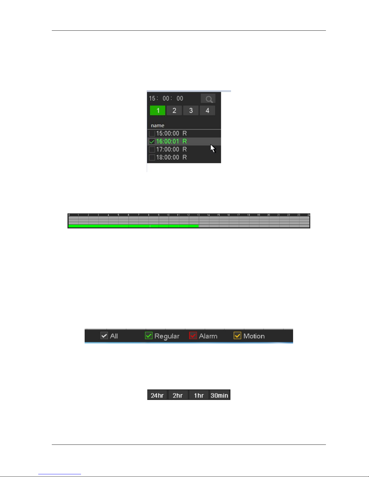
Smart search
Select records from one day, click the list, you can go to the file list interface. You can input time at
thetop right corner to search records by time.
input time 11:00.00 and then click Search buttonyou can view all the record files after 11:00.00(The
records includes current time.)
Page 26
HDCVR
- 26 -
Double click a filename to playback
Note
After you searched files, system implement accurate playback once you click Play for the firsttime.
System does not support accurate playback for picture
System supports synchronization playback and non-synchronous playback. The synchronization
playback supports all channels and non-synchronous playback only supports accurately
playback of current select channel.
Figure 3- 12
Time bar
Figure 3- 13
It is to display the record type and its period in current search criteria.In 4-window playback mode, there
are corresponding four time bars. In otherplayback mode, there is only one time bar.
Use the mouse to click one point of the color zone in the time bar, system beginsplayback.
The time bar is beginning with 0 o'clock when you are setting the configuration.
The time bar zooms in the period of the current playback time when you areplaying the file.
The green color stands for the regular record file. The red color stands for theexternal alarm record file.
The yellow stands for the motion detect record file
File type
File type: R—regular record; A—external alarm record; M—Motion detect record.
Figure 3- 14
Time bar unit
Figure 3- 15
The option includes: 24H, 12H, 1H and 30M. The smaller the unit, the larger the zoom rate. You can
accurately set the time in the time bar to playback the record.
The time bar is beginning with 0 o'clock when you are setting the configuration.
Page 27
HDCVR
- 27 -
The time bar zooms in the period of the current playback time when you areplaying the file.
3.3
Main Menu
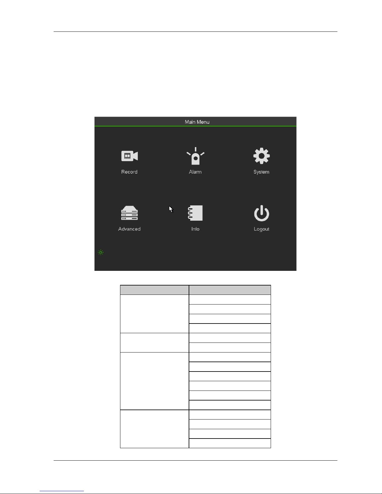
3.3.1Main Menu
The main menu interface is shown as below
。
Figure 3- 16
Main
Second menu
Record
Schedule
Play back
Record
Backup
Alarm
Motion
Abnormaliti
System
General
Encode
Network
Network server
Display
PTZ
Advanced
HDD
Config Backup
Account
Online User
Page 28
HDCVR
- 28 -
Main
Second menu
Auto Maintain
ATM/POS
Default
Digital
Info
HDD Info
BPS
LOG
Version
NETWORK
Logout
-
3.3.2 Record
Record
Note:
You need to have proper rights to implement the following operations. Please make sure the HDDshave
been properly installed.
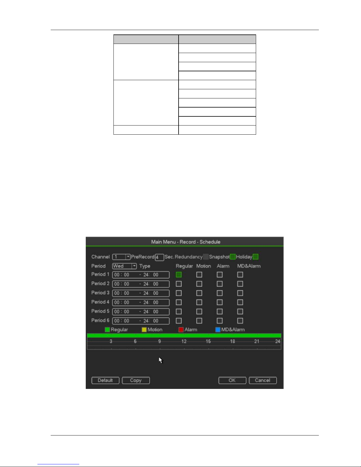
After the system booted up, it is in default 24-hour regular mode. You can set record type and time
inschedule interface.
Figure 3- 17
Channel: Please select the channel number first. You can select “all” if you want to set for the whole
channels.
Record Type: Please check the box to select corresponding record type. There are four types:
Page 29
HDCVR
- 29 -
Regular/MD (motion detect)/Alarm/MD&Alarm.
Week day: There are eight options: ranges from Saturday to Sunday and all.
Holiday: It is to set holiday setup. Please note you need to go to the General interface (Main Menu
->System->General) to add holiday first. Otherwise you can not see this item.
Pre-record: System can pre-record the video before the event occurs into the file. The value rangesfrom 1
to 30 seconds depending on the bit stream .
Redundancy: System supports redundancy backup function. You can highlight Redundancy buttonto
activate this function. Please note, before enable this function, please set at least one HDD asredundant.
(Main menu->Setting->Storage->HDD Manager).
Please note this function is null ifthere is only one HDD.
Backup
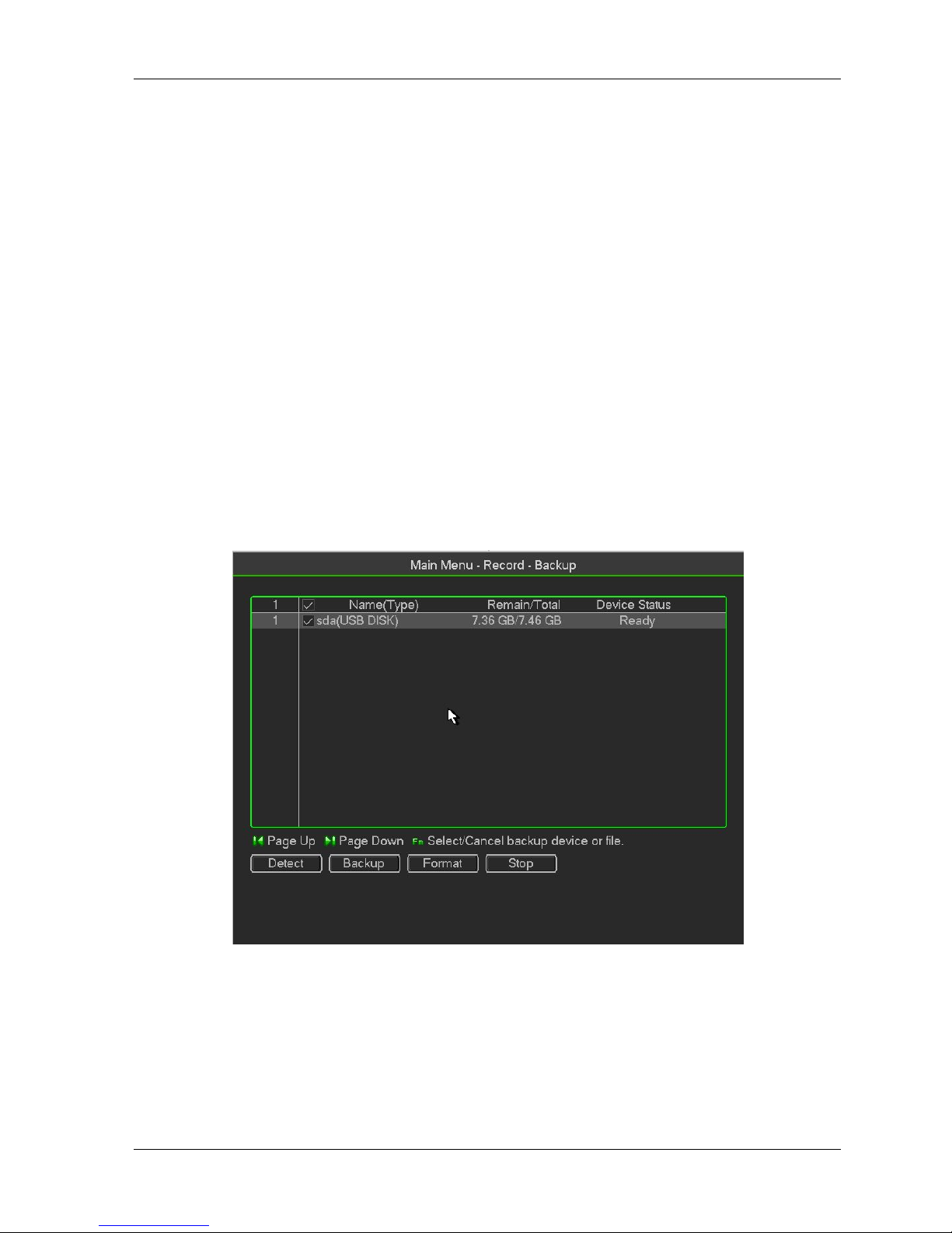
DVR support CD-RW, DVD burner, USB device backup, network download and eSATA. Here
weintroduce USB, eSATA backup. You can refer to Chapter 5 Web Operation for network
downloadbackup operation.
Click backup button, you can see an interface is shown as in Figure 3-21. Here is for you to viewdevices
information.
You can view backup device name and its total space and free space. The device includes CD -RW,DVD
burner, USB device, flash disk, eSATA backup.
Figure 3- 18
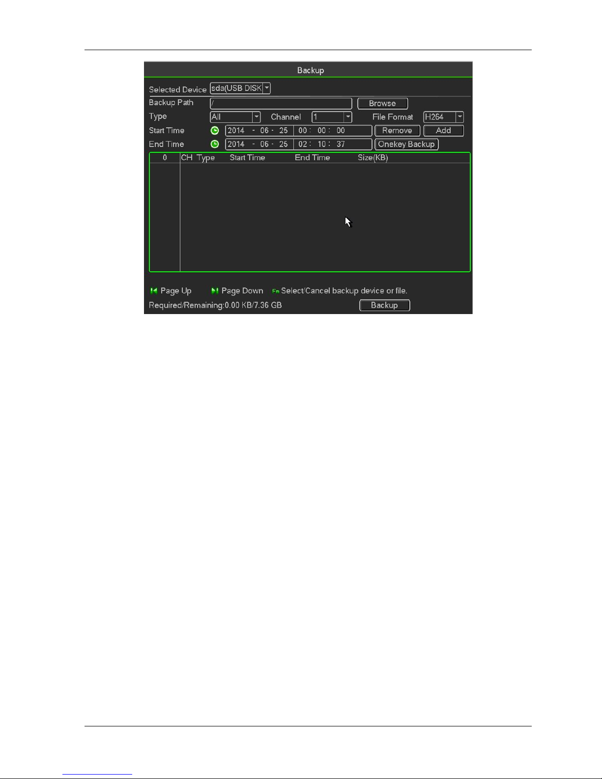
Select backup device and then set channel, file start time and end time.
Click add button, system begins search. All matched files are listed below. System
automaticallycalculates the capacity needed and remained
System only backup files with a √ before channel name. You can use Fn or cancel button to delete√ after
file serial number.
Click Start button, system begins copy. At the same time, the backup button becomes stop button.You
can view the remaining time and process bar at the left bottom
Page 30
HDCVR
- 30 -
Figure 3- 19
When the system completes backup, you can see a dialogue box prompting successful backup
File format: Click the file format; you can see there are two options: DAV/ASF.
The file name format usually is: Channel number+Record type+Time. In the file name, the YDM
format is Y+M+D+H+M+S. File extension name is .dav.
Tips:
During backup process, you can click ESC to exit current interface for other operation. The systemwill not
terminate backup process
Note:
When you click stop button during the burning process, the stop function becomes activatedimmediately.
For example, if there are ten files, when you click stop system just backup five files,system only save the
previous 5 files in the device (But you can view ten file names).
Alarm
Detect
In the main menu, from Manu->Alarm->Detect, you can see motion detect interface. There is three detection
types: motion detection, video loss, tampering
The video loss has no detection region and sensitivity setup and tampering has no detectionregion setup.
You can see motion detect icon if current channel has enabled motion detect alarm.
You can drag you mouse to set motion detect region. Please click OK button to save current.region setup.
Right click mouse to exit current interface.
3.3.2.4.1
Motion Detect
After analysis video, system can generate a video loss alarm when the detected moving signal reachedthe
sensitivity you set here.
Page 31

HDCVR
- 31 -
Event type: From the dropdown list you can select motion detection type.
Channel: Select a channel from the dropdown list to set motion detect function.
Enable: Check the box here to enable motion detect function.
Region: Click select button, the interface is shown as in Figure 3-25. Here you can set
motiondetection zone. There are four zones for you to set. Please select a zone first and then left
drag themouse to select a zone. The corresponding color zone displays different detection zone.
You canclick Fn button to switch between the arm mode and disarm mode. In arm mode, you can
click thedirection buttons to move the green rectangle to set the motion detection zone. After you
completedthe setup, please click ENTER button to exit current setup. Do remember click save
button to savecurrent setup. If you click ESC button to exit the region setup interface system will not
save yourzone setup.
Sensitivity: System supports 6 levels. The sixth level has the highest sensitivity.
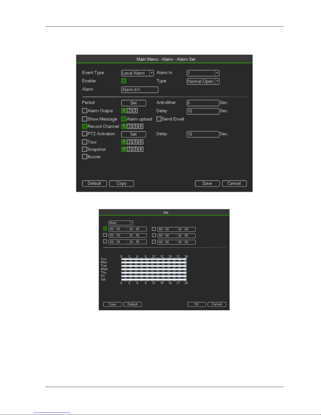
Figure 3- 20
Anti-dither: Here you can set anti-dither time. The value ranges from 5 to 600s. The anti-dither
timerefers to the alarm signal lasts time. It can be seem as the alarm signal activation stays such as
thebuzzer, tour, PTZ activation, snapshot, channel record. The stay time her e does not include
thelatch time. During the alarm process, the alarm signal can begin an anti-dither time if system
detectsthe local alarm again. The screen prompt, alarm upload, email and etc will not be activated.
Forexample, if you set the anti-dither time as 10 second, you can see the each activation may last
10sif the local alarm is activated. During the process, if system detects another local alarm signal at
thefifth second, the buzzer, tour, PTZactivation, snapshot, record channel will begin another
10swhile the screen prompt, alarm upload, email will not be activated again. After 10s, if system
detectsanother alarm signal, it can generate an alarm since the anti -dither time is out.
Period: Click set button, you can see an interface. Here you can setmotion detect period. System
only enables motion detect operation in the specified periods. It is notfor video loss or the
Page 32

HDCVR
- 32 -
tampering. There are two ways for you to set periods. Please note system onlysupports 6 periods
in one day
Figure 3- 21
There are four record types: regular, motion detection (MD), Alarm, MD & alarm.
Alarm output: when an alarm occurs, system enables peripheral alarm devices.
Latch: when motion detection complete, system auto delays detecting for a specified time. Thevalue
ranges from 1-300(Unit: second)Show message: System can pop up a message to alarm you in the local
host screen if you enabledthis function.
Alarm upload: System can upload the alarm signal to the network (including alarm centre) if you
enabled current function.
Send email: System can send out email to alert you when an alarm occurs.
Record channel: System auto activates motion detection channel(s) to record once an alarm occurs.
Please make sure you have set MD record in Schedule interface(Main Menu->Setting->Schedule)and
schedule record in manual record interface(Main Menu->Advanced->Manual Record)PTZ activation:
Here you can set PTZ movement when an alarm occurs. Such as go to preset, tour&pattern when there is
an alarm. Click “select” button, you can see an interface is shown as in
X
Record Delay: System can delay the record for specified time after alarm ended. The value rangesfrom
10s to 300s.
Tour: Here you can enable tour function when alarm occurs. System one-window tour.
Snapshot: You can enable this function to snapshoot image when a motion detect alarm occurs.
Video matrix Check the box here to enable this function. When an alarm occurs, SPOT OUT portdisplays
device video output. It displays video (1-window tour) from alarm activation channel youselect at the
Record channel item.
Buzzer: Highlight the icon to enable this function. The buzzer beeps when alarm occurs.
Test: Click it to test current motion detect setup (do not need to save). Click Select button afterRegion,
you can set motion detect area.
Please highlight iconto select the corresponding function. After all the setups please click savebutton, system
goes back to the previous menu.
Note:
In motion detection mode, you can not use copy/paste to set channel setup since the video in eachchannel
Page 33
HDCVR
- 33 -
may not be the same, you can left click mouse and then drag it to set a region for motion detection. Click Fn
toswitch between arm/withdraw motion detection. After setting, click enter button to exitMotion detect here
only has relationship with the sensitivity and region setup. It has no relationshipwith other setups.
Figure 3- 22
Figure 3- 23
Video Loss
Page 34

HDCVR
- 34 -
Figure 3- 24
Select video loss from the type list. You can see the interface is shown This function allows you to be informed
when video loss phenomenon occurred. You canenable alarm output channel and then enable show essage
function.
Tips:
You can enable preset/tour/pattern activation operation when video loss occurs.
Please refer to chapter 4.10.3.1.1 motion detection for detailed information.
Tampering
When someone viciously masks the lens, or the output video is in one-color due to the environmentslight
change, the system can alert you to guarantee video continuity. Tampering interface is shownYou can enable
“Alarm output “or “Show message” function when tamperingalarm occurs
Sensitivity: The value ranges from 1 to 6. It mainly concerns the brightness. The level 6 has thehigher
sensitivity than level 1. The default setup is 3
Tips:
You can enable preset/tour/pattern activation operation when video loss occurs.
Please refer to chapter 4.10.3.1.1 motion detection for detailed information.
Note:
In Detect interface, copy/paste function is only valid for the same type, which means you cannot copy a
channel setup in video loss mode to tampering mode.
About Default function. Since detection channel and detection type may not be the same,system can only
restore default setup of current detect type. For example, if you click Defaultbutton at the tampering interface,
you can only restore default tampering setup. It is null for otherdetect types.
System only enables tampering function during the period you set here. It is null for motion
detect or video loss type.
Page 35

HDCVR
- 35 -
3.3.3 System
Figure 3- 25
Page 36

HDCVR
- 36 -
General
Figure 3- 26
Device ID: Please input a corresponding device name here.
Device No: Here you can set device number.
Language: System supports various languages: Chinese (simplified), Chinese (Traditional), English,Italian,
Japanese, French, Spanish (All languages listed here are optional. Slight difference may befound in various
series.)
Video standard: There are two formats: NTSC and PAL.
HDD full: Here is for you to select working mode when hard disk is full. There are two options:
stoprecording or rewrite. If current working HDD is overwritten or the current HDD is full while the nextHDD is
no empty, then system stops recording, If the current HDD is full and then next HDD is notempty, then system
overwrites the previous files.
Pack duration: Here is for you to specify record duration. The value ranges from 1 to 120 minutes.
Default value is 60 minutes.
Real-time playback: It is to set playback time you can view in the preview interface. The valueranges from
5 to 60 minutes.
Auto logout: Here is for you to set auto logout interval once login user remains inactive for aspecified time.
Value ranges from 0 to 60 minutes.
Navigation bar: Check the box here, system displays the navigation bar on the interface.
Startup wizard: Once you check the box here, system will go to the startup wizard directly when thesystem
restarts the next time. Otherwise, it will go to the login interface.
Mouse property: You can set double click speed via dragging the slide bard. You can
Click Defaultbutton to restore default setup.
Date and Time:
Date format: There are three types: YYYYY-MM-DD: MM-DD-YYYYY or DD-MM-YYYY.
Page 37

HDCVR
- 37 -
Date separator: There are three denotations to separate date: dot, beeline and solidus.
DST: Here you can set DST time and date. Here you can set start time and end time by
settingcorresponding week setup or by setting corresponding date setup.
NTP: It is to set NTP server information
Figure 3- 27
Holiday:
Holiday setup interface is shown as in Figure 4-100. Click Add new holiday button, you can input
newholiday information. See Figure 4-101. Here you can set holiday name, repeat mode and start/end
time
Note
When you enable Holiday settings and schedule setup at the same time, holiday setting has thepriority. If
the selected day is a holiday, then system records as you set in holiday s etting. If it is nota holiday,
system records as you set in Schedule interface.
Please notePlease note, there is no year setup on the holiday setup. For example, if you set 30th Oct,
2012 asa holiday, then the date of 30th Oct in each year will be set as a holiday.
Figure 3- 28
Encode
It is to set video bit stream, picture bit stream, video overlay parameter and etc
Page 38

HDCVR
- 38 -
Figure 3- 29
Channel: Select the channel you want.
Type: Please select from the dropdown list. There are three options: regular/motion detect/alarm.
You can set the various encode parameters for different record typesCompression: System
supports H.264 and MJPEG.
Resolution: System supports various resolutions, you can select from the dropdown list. Please
notethe option may vary due to different series.
Frame rate: It ranges from 1f/s to 25f/s in NTSC mode and 1f/s to 30f/s in PAL mode.
Bit rate type: System supports two types: CBR and VBR. In VBR mode, you can set video quality.
Quality: There are six levels ranging from 1 to 6. The sixth level has the highest image quality.
Video/audio: You can enable or disable the video/audio.
Audio: Please select from the dropdown list.
3.3.3.4.1
Overlay
Figure 3- 30
Cover area: Here is for you to set cover area. You can drag you mouse to set proper section size. Inone
Page 39

HDCVR
- 39 -
channel video, system max supports 4 zones in one channel.
Preview/monitor: privacy mask has two types. Preview and Monitor. Preview means the privacymask
zone can not be viewed by user when system is in preview status. Monitor means the privacymask zone
can not be view by the user when system is in monitor status.
Time display: You can select system displays time or not when you playback. Please click setbutton and
then drag the title to the corresponding position in the screen.
Channel display: You can select system displays channel number or not when you playback. Pleaseclick
set button and then drag the title to the corresponding position in the screen.
Copy:After you complete the setup, you can click Copy button to copy current setup to otherchannel(s).
You can see an interface is shown as in Figure 3-43. You can see current channelnumber is grey. Please
check the number to select the channel or you can check the box ALL.
Please click the OK button in Figure 3-43 and Figure 3-41 respectively to complete the setup.
Figure 3- 31
Snapshot
Here you can set snapshot mode, picture size, quality and frequency.
Snapshot mode: There are two modes: regular and trigger. If you set timing mode, you need to
setsnapshot frequency. If you set trigger snapshot, you need to set snapshot activation operation.
Image size: Here you can set snapshot picture size.
Image quality: Here you can set snapshot quality. The value ranges from 1 to 6.
Interval: It is for you to set timing (schedule) snapshot interval.
“Menu > Record > Record Set”,Open “Snapshot”。
Page 40

HDCVR
- 40 -
Figure 3- 32
Trigger Snapshot
Please follow the steps listed below to enable the activation snapshot function. After you enabledthis function,
system can snapshot when the corresponding alarm occurred
In main menu, from Menu->Record->Record set, here you can input snapshotmode as regular, size, quality
and frequency
Figure 3- 33
In main menu, from Menu->Alarm->Detect, please enable snapshot function for specified channels
Page 41

HDCVR
- 41 -
Figure 3- 34
Image FTP
In the main menu, from Setting->Network->FTP, you can set FTP server information. Please enableFTP
function and then click save button
Figure 3- 35
Page 42
HDCVR
- 42 -
Network
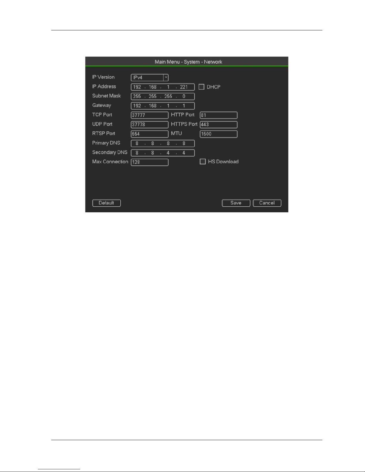
Figure 3- 36
IP Version: There are two options: IPv4 and IPv6. Right now, system supports these two IP
addressformat and you can access via them.
MAC address: The host in the LAN can get a unique MAC address. It is for you to access in the LAN. Itis
read-only.
IP address: Here you can use up/down button () or input the corresponding number to input
IPaddress. Then you can set the corresponding subnet mask the default gateway.
Default gateway: Here you can input the default gateway. Please note system needs to check thevalidity
of all IPv6 addresses. The IP address and the default gateway shall be in the same IP
section. That is to say, the specified length of the subnet prefix shall have the same string.
DHCP: It is to auto search IP. When enable DHCP function, you can not modify IP/Subnet mask/Gateway.
These values are from DHCP function. If you have not enabled DHC P function,
IP/Subnet mask/Gateway display as zero. You need to disable DHCP function to view current
IPinformation. Besides, when PPPoE is operating, you can not modify IP/Subnet mask /Gateway.
MTU: It is to set MTU value of the network adapter. The value ranges from 1280-7200 bytes.
Thedefault setup is 1500 bytes. Please note MTU modification may result in network adapter reboot
andnetwork becomes off. That is to say, MTU modification can affect current network service. Systemmay pop
up dialog box for you to confirm setup when you want to change MTU setup. Click OKbutton to confirm current
reboot, or you can click Cancel button to terminate current modification.Before the modification, you can check
the MTU of the gateway; the MTU of the DVR shall be thesame as or is lower than the MTU of the gateway. In
this way, you can reduce packets and enhancenetwork transmission efficiency.
The following MTU value is for reference only.
1500: Ethernet information packet max value and it is also the default value. It is the typicalsetup when
Page 43

HDCVR
- 43 -
there is no PPPoE or VPN. It is the default setup of some router, switch or thenetwork adapter.
1492: Recommend value for PPPoE.
1468: Recommend value for DHCP.
Preferred DNS server: DNS server IP address.
Alternate DNS server: DNS server alternate address.
Transfer mode: Here you can select the priority between fluency/video qualities.
LAN download: System can process the downloaded data first if you enable this function. Thedownload
speed is 1.5X or 2.0X of the normal speed.
LAN download: System can process the downloaded data first if you enable this function. Thedownload
speed is 1.5X or 2.0X of the normal speed.
After completing all the setups please click save button, system goes back to the previous menu.
Network service
Figure 3- 37
IP Filter
IP filter interface is shown as in Figure 4-61. You can add IP in the following list. The list supports max64 IP
addresses. System supports valid address of IPv4 and IPv6. Please note system needs tocheck the
validity of all IPv6 addresses and implement optimization.
After you enabled trusted sites function, only the IP listed below can access current DVR.
If you enable blocked sites function, the following listed IP addresses can not access current DVR
Enable: Highlight the box here, you can check the trusted site function and blocked sites function.
Page 44

HDCVR
- 44 -
You can not see these two modes if the Enable button is grey.
Type: You can select trusted site and blacklist from the dropdown list. You can view the IP addresson the
following column.
Start address/end address: Select one type from the dropdown list, you can input IP address in the
start address and end address. Now you can click Add IP address or Add IP section to add
For the newly added IP address, it is in enable status by default. Remove the √ before the item,and then
current item is not in the list.
System max supports 64 items.
Address column supports IPv4 or IPv6 format. If it is IPv6 address, system can optimize it. Forexample,
system can optimize aa:0000: 00: 00aa: 00aa: 00aa: 00aa: 00aa as aa:: aa: aa: aa:aa: aa: aa.
System automatically removes space if there is any space before or after the newly added IPaddress.
System only checks start address if you add IP address. System check start address and endaddress if
you add IP section and the end address shall be larger than the start address.
System may check newly added IP address exists or not. System does not add if input IPaddress does
not exist.
Delete: Click it to remove specified item.
Edit: Click it to edit start address and end address. See Figure 4-62. System can check the IPaddress
validity after the edit operation and implement IPv6 optimization.
Default: Click it to restore default setup. In this case, the trusted sites and blocked sites are both
null.
Note:
If you enabled trusted sites, only the IP in the trusted sites list can access the device.
If you enabled blocked sites, the IP in the blocked sites can not access the device.
System supports add MAC address.
Figure 3- 38
Page 45

HDCVR
- 45 -
Multicast
Figure 3- 39
Here you can set a multiple cast group. Please refer to the following sheet for detailed information.
IP multiple cast group address
-224.0.0.0-239.255.255.255
- “ D” address space
The higher four-bit of the first byte= ” 1110”
Reserved local multiple cast group address
-224.0.0.0-224.0.0.255
-TTL=1 When sending out telegraph
-For example
224.0.0.1All systems in the sub-net
224.0.0.2All routers in the sub-ne
224.0.0.4DVMRP router
224.0.0.5OSPF router
224.0.0.13 PIMv2 router
Administrative scoped addressees
-239.0.0.0-239.255.255.255
-Private address space
Like the single broadcast address of RFC1918
Can not be used in Internet transmission
Used for multiple cast broadcast in limited space.
Except the above mentioned addresses of special meaning, you can use other addresses. For example:
Multiple cast IP: 235.8.8.36
Multiple cast PORT: 3666.
After you logged in the Web, the Web can automatically get multiple cast address and add it to themultiple
cast groups. You can enable real-time monitor function to view the view.
Please note multiple cast function applies to special series only.
PPPoE
Input “PPPoE name” and “PPPoE password” you get from your ISP (Internet service provider).
Click save button, you need to restart to activate your configuration.
After rebooting, DVR will connect to internet automatically. The IP in the PPPoE is the DVR dynamicvalue.
You can access this IP to visit the unit.
Page 46
HDCVR
- 46 -
Figure 3- 40
DDNS
You need a PC of fixed IP in the internet and there is the DDNS software running in this PC. In otherwords,
this PC is a DNS (domain name server).
In network DDNS, please select DDNS type and highlight enable item. Them please input your PPPoEname
you get from you IPS and server IP (PC with DDNS). Click save button and then reboot system.
Click save button, system prompts for rebooting to get all setup activated.
After rebooting, open IE and input as below:
http://(DDNS server IP)/(virtual directory name)/webtest.htm
e.g.: http://10.6.2.85/DVR _DDNS/webtest.htm.)
Now you can open DDNSServer web search page.
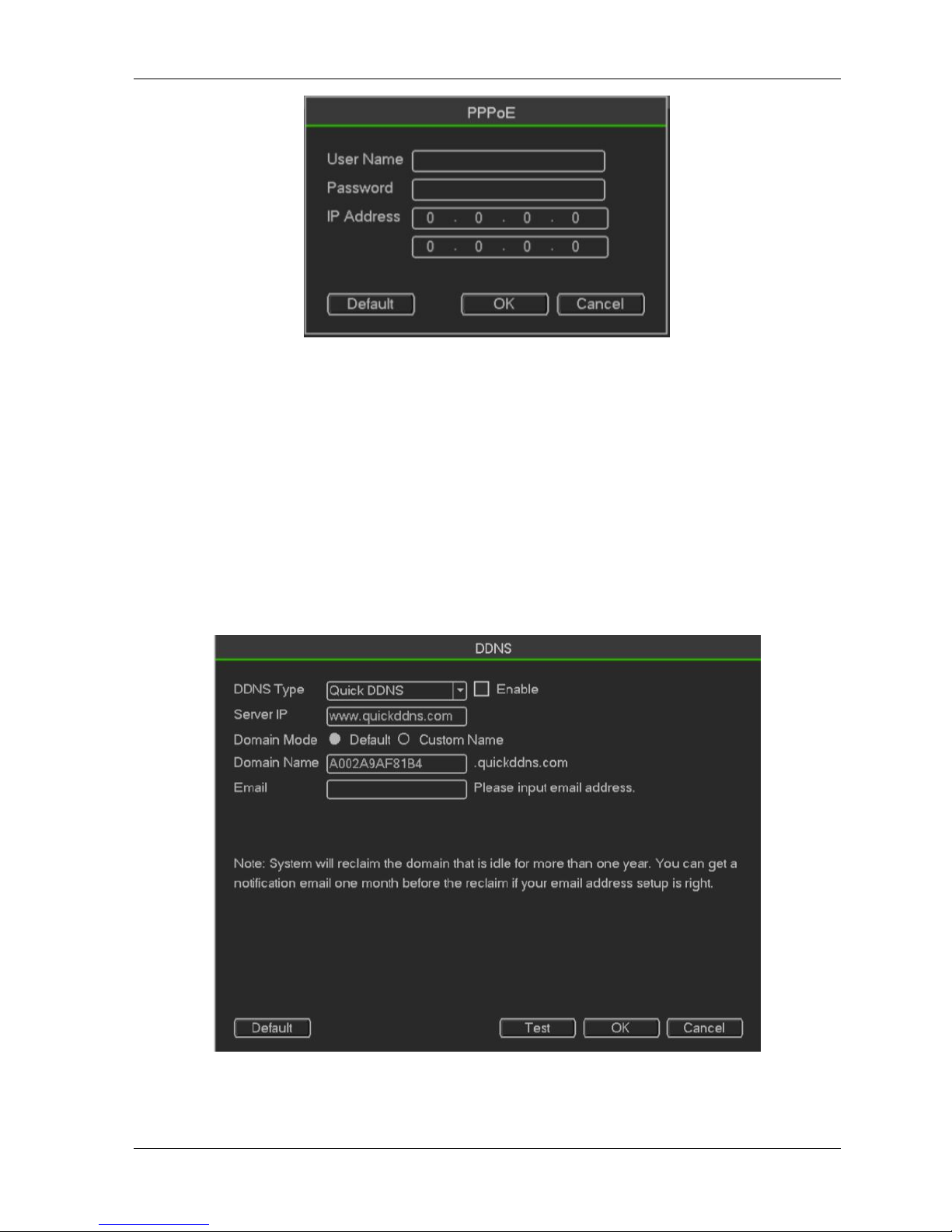
Figure 3- 41
Please note NNDS type includes: CN99 DDNS, NO-IP DDNS, Quick DDNS, Dyndns DDNS and
sysdnsDDNS. All the DDNS can be valid at the same time, you can select as you requirement.
Page 47

HDCVR
- 47 -
Private DDNS function shall work with special DDNS server and special Professional Surveillance
Software (PSS).
Quick DDNS and Client-end Introduction
1) Background Introduction
Device IP is not fixed if you use ADSL to login the network. The DDNS function allows you to access
theDVR via the registered domain name. Besides the general DDNS ,the Quick DDNS works with thedevice
from the manufacturer so that it can add the extension function.
2) Function Introduction
The quick DDNS client has the same function as other DDNS client end. It realizes the bonding of
thedomain name and the IP address. Right now, current DDNS server is for our own devices only. Youneed
to refresh the bonding relationship of the domain and the IP regularly. There is no user name,password or
the ID registration on the server. At the same time, each device has a default domain name(Generated by
MAC address) for your option. You can also use customized valid domain name (has notregistered.).
3) Operation
Before you use Quick DDNS, you need to enable this service and set proper server address, port valueand
domain name.
Server address:www.quickddns.com
Port number:80
Domain name:There are two modes: Default domain name and customized domain name.
Except default domain name registration, you can also use customized domain name (You can inputyour
self-defined domain name.) After successful registration, you can use domain name to logininstalled of the
device IP.
Do not register frequently. The interval between two registrations shall be more than 60 seconds.
Too many registration requests may result in server attack.
System may take back the domain name that is idle for one year. You can get a notification emailbefore the
cancel operation if your email address setup is OK.
UPnP
The UPNP protocol is to establish a mapping relationship between the LAN and the WAN. Please
inputthe router IP address in the LAN
Page 48

HDCVR
- 48 -
Figure 3- 42
UPNP on/off:Turn on or off the UPNP function of the device.
Status: When the UPNP is offline, it shows as “Unknown”. When the UPNP works it shows“Success”.
Router LAN IP: It is the router IP in the LAN.
WAN IP: It is the router IP in the WAN.
Port Mapping list: The port mapping list here is the one to one relationship with the router’s portmapping
setting.
List:
Service name:Defined by user.
Protocol: Protocol type
Internal port:Port that has been mapped in the router.
External port:Port that has been mapped locally.
Default: UPNP default port setting is the HTTP, TCP and UDP of the DVR.
Add to the list: Click it to add the mapping relationship.
Delete: Click it to remove one mapping item.
Double click one item; you can change the corresponding mapping information.
Important:
When you are setting the router external port, please use 1024~5000 port. Do not use
well-known
port 1~255 and the system port 256~1023 to avoid conflict.
For the TCP and UDP, please make sure the internal port and external port are the same
toguarantee the proper data transmission.
Page 49

HDCVR
- 49 -
Figure 3- 43
3G
Please refer to the following contents for the parameter information
Figure 3- 44
Pane 1: Display 3G signal intensity after you enabled 3G function.
Pane 2: Display 3G module configuration information after you enabled 3G function.
Pane 3: Display 3G module status information after you enabled 3G function.
It is to display current wireless network signal intensity such as EVDO, CDMA1x, WCDMA, CDMA,EDGE
and etc.
3G module: It is to display current wireless network adapter name.
3G Enable/Disable: Check the box here to enable 3G module.
Network type: There are various network types for different 3G network modules. You can
selectaccording to your requirements.
APN: It is the wireless connection server. It is to set you access the wireless network via
whichmethod.
Page 50

HDCVR
- 50 -
AUTH: It is the authentication mode. It supports PAP/CHAP.
Dial number: Please input 3G network dialup number you got from your ISP.
User name: It is the user name for you to login the 3G network.
Password: It is the password for you to login the 3G network.
Pulse interval: You can set dialup duration. Once you disable the extra stream, the connection
timebegins. For example, if you input 5 seconds here, then 3G network connection period is 5
seconds.
The device automatically disconnect when time is up. If there is no extra stream, 3G
networkconnection is valid all the time. If the alive time is 0, then the 3G network connection is
valid allthe time.
Dial: Here you can enable or disable 3G network connection/disconnection manually.
3G wireless network: Here is to display wireless network status, SIM card status, dial status. If the3G
connection is OK, then you can see the device IP address the wireless network
automaticallyallocates.
WIFI
Figure 3- 45
The WIFI interface is shown as below.
Auto connect WIFI: Check the box here, system automatically connects to the previous WIFIhotspot.
Refresh: You can click it to search the hotspot list again. It can automatically add the information
such as the
password if you have set it before.
Disconnect: Here you can click it to turn off the connection.
Connect: Here you can click it to connect to the hotspot. System needs to turn off currentconnection and
then connect to a new hotspot if there is connection of you selected one.
WIFI working status: Here you can view current connection status.
Please note:
After successful connection, you can see WIFI connection icon at the top right corner of the
Page 51

HDCVR
- 51 -
previewinterface.
When the hotspot verification type is WEP, system displays as AUTO since the device can notdetect its
encryption type.
System does not support verification type WPA and WPA2. The display may become abnormal forthe
verification type and encryption type.
After device successfully connected to the WIFI, you can view the hotspot name, IP address, subnetmask,
default gateway and etc
Email
SMTP server: Please input your email SMTP server IP here.
Port: Please input corresponding port value here.
User name: Please input the user name to login the sender email box.
Password: Please input the corresponding password here.
Sender: Please input sender email box here.
Title: Please input email subject here. System support English character and Arabic number. Max
32-digit.
Receiver: Please input receiver email address here. System max supports 3 email boxes.
System
automatically filters same addresses if you input one receiver repeatedly.
SSL enable: System supports SSL encryption box.
Interval: The send interval ranges from 0 to 3600 seconds. 0 means there is no interval.
Health email enable: Please check the box here to enable this function. This function allows thesystem to
send out the test email to check the connection is OK or not.
Interval: Please check the above box to enable this function and then set the corresponding interval.
System can send out the email regularly as you set here. Click the Test button, you can see
thecorresponding dialogue box to see the email connection is OK or not.
Please note system will not send out the email immediately when the alarm occurs. When the alarm,motion
detection or the abnormity event activates the email, system sends out the email according to theinterval you
specified here. This function is very useful when there are too many emails activated by theabnormity events,
which may result in heavy load for the email server.
Page 52

HDCVR
- 52 -
Figure 3- 46
FTP
You need to download or buy FTP service tool (such as Ser-U FTP SERVER) to establish FTP
service.Please install Ser-U FTP SERVER first. From “start” -> “program” -> Serv-U FTP Server ->
Serv-UAdministator. Now you can set user password and FTP folder. Please note you need to grant write
rightto FTP upload user
Figure 3- 47
Page 53

HDCVR
- 53 -
Figure 3- 48
Figure 3- 49
You can use a PC or FTP login tool to test setup is right or not.For example, you can login user ZHY to
H140H140H140HTUFTP://10.10.7.7UTH and then test it can modify or delete folder or not.
System also supports upload multiple DVRs to one FTP server. You can create multiple folders underthis
FTP.
Please highlight the iconn front of Enable to activate FTP function.
Here you can input FTP server address, port and remote directory. When remote directory is null,
system automatically create folders according to the IP, time and channel.
User name and password is the account information for you to login the FTP.
File length is upload file length. When setup is larger than the actual file length, system will upload thewhole
file. When setup here is smaller than the actual file length, system only uploads the set length andauto ignore
the left section. When interval value is 0, system uploads all corresponding files.After completed channel and
weekday setup, you can set two periods for one each channel.Click the Test button, you can see the
corresponding dialogue box to see the FTP connection is OK ornot.
Page 54

HDCVR
- 54 -
Figure3- 1
Figure3- 2
Alarm Centre
This interface is reserved for you to develop
.
Figure 3- 50
Page 55

HDCVR
- 55 -
SNMP
SNMP is an abbreviation of Simple Network Management Protocol. It provides the basic
networkmanagement frame of the network management system. The SNMP widely used in many
environments.It is used in many network device, software and system.
You can set in the following interface
。
Figure 3- 51
Please enable the SNMP function. Use the corresponding software tool (MIB Builder and MG-SOFT
MIBBrowser. You still need two MIB file: BASE-SNMP-MIB, DVR-SNMP-MIB) to connect to the device.
Youcan get the device corresponding configuration information after successfully connection.
Please follow the steps listed below to configure.
Check the box to enable the SNMP function. Input the IP address of the PC than isrunning the
software in the Trap address. You can use default setup for the rest items.
Compile the above mentioned two MIB file via the software MIB Builder.
Run MG-SOFT MIB Browser to load the file from the previous step to the software.
Input the device IP you want to manage in the MG-SOFT MIB Browser. Please set thecorresponding
version for your future reference.
Open the tree list on the MG-SOFT MIB Browser; you can get the device configuration. Here youcan
see the device has how many video channels, audio channels, application version and etc.
Note
Port conflict occurs when SNMP port and Trap port are the same.
Register
This function allows the device to auto register to the proxy you specified. In this way, you can use
theclient-end to access the DVR and etc via the proxy. Here the proxy has a switch function. In the
networkservice, device supports the server address of IPv4 or domain.
Please follow the steps listed below to use this function.
Page 56

HDCVR
- 56 -
Please set proxy server address, port, and sub-device name at the device-end. Please enable the auto
register function, the device can auto register to the proxy server.
Important
Do not input network default port such as TCP port number
Figure 3- 52
The proxy server software developed from the SDK. Please open the software and input the global setup.
Please make sure the auto connection port here is the same as the port you set in the previous step.
Now you can add device. Please do not input default port number such as the TCP port in the mapping port
number. The device ID here shall be the same with the ID you input in Figure 4-71. Click Add button to
complete the setup.
Now you can boot up the proxy server. When you see the network status is Y, it means your registration is OK.
You can view the proxy server when the device is online.
Important
The server IP address can also be domain. But you need to register a domain name before you run
proxy device server.
P2P setting
Enable the function of P2P, and double click the mouse to check the status,also get the series No and APP for
andriod,apple from QR.
Page 57
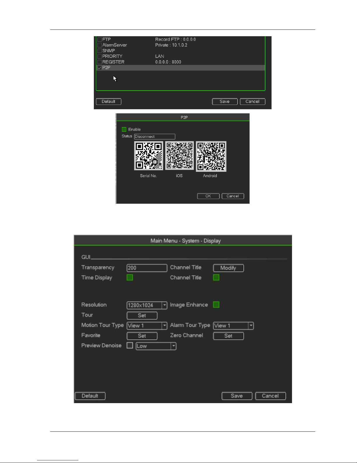
HDCVR
- 57 -
Display
Figure 3- 53
Display
Page 58
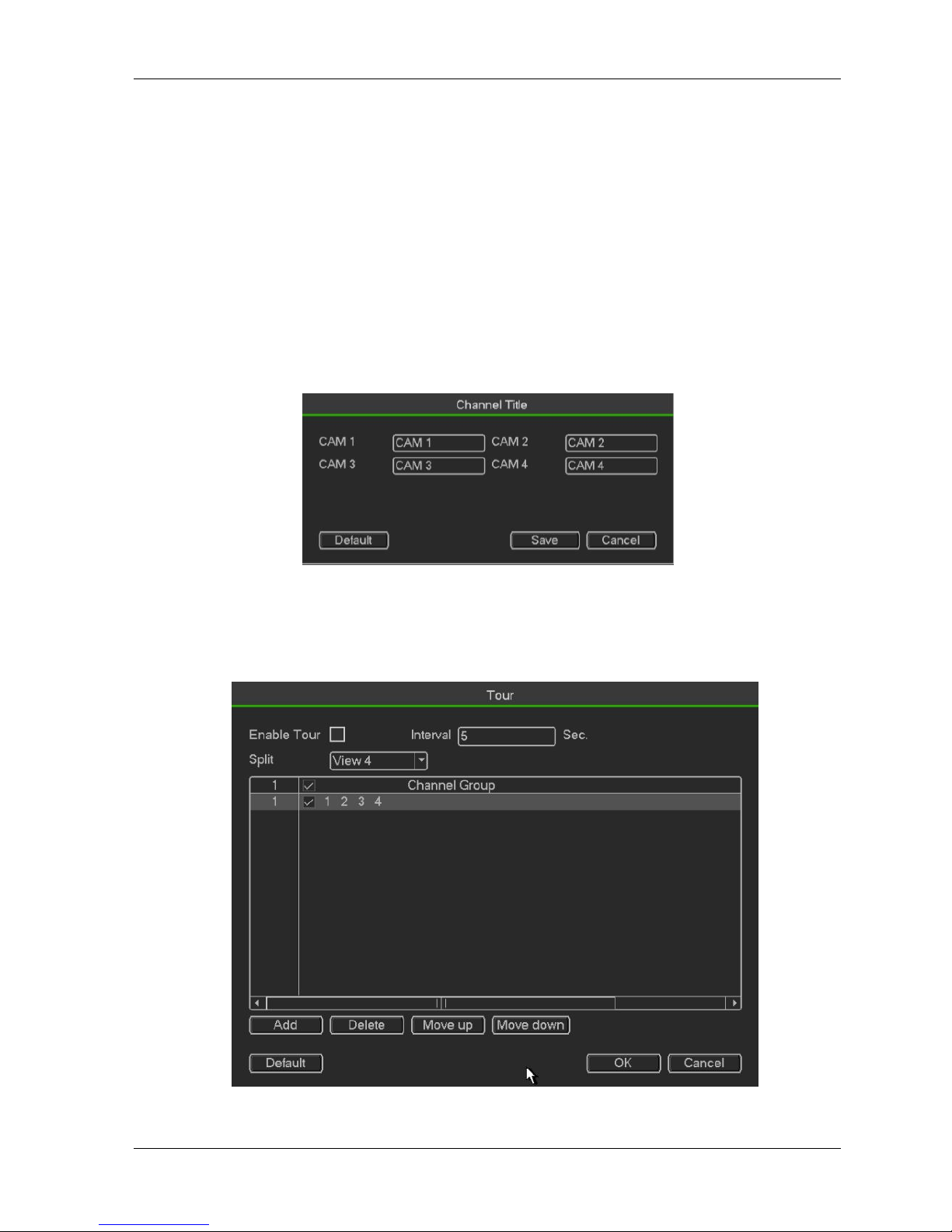
HDCVR
- 58 -
Transparency: Here is for you to adjust transparency. The value ranges from 128 to 255.
Channel name: Here is for you to modify channel name. System max support 25-digit (The
valuemay vary due to different series). Please note all your modification here only applies to
DVR localend. You need to open web or client end to refresh channel name.
Time display: You can select to display time or not when system is playback.
Channel display: You can select to channel name or not when system is playback.
Resolution: There are four options: 1920×1080, 1280×1024(default),1280×720,1024×768.
Pleasenote the system needs to reboot to activate current setup.
Image enhance: Check the box; you can optimize the margin of the preview video.
Preview denoise: It is to reduce the video noise and make it clearer. You can set denoise level.
Thehigher the level is, the clearer the video is.
Please highlight iconto select the corresponding function. After completing all the setups please
click save button, system g oes back to the previous menu.
Figure 3- 54
It is to modify channel name.
Channel Type
It is to set channel type. It supports coaxiable/UTP.
Figure 3- 55
Page 59

HDCVR
- 59 -
3.3.4 Information
Figure 3- 56
HDD Information
Here is to list hard disk type, total space, free space, video start time and status.
SATA: 1 here means system max supports 1 HDD. ○ means current HDD is normal. X means thereis error. -
means there is no HDD. If disk is damaged, system shows as “?”. Please remove thebroken hard disk before
you add a new one.
SN: You can view the HDD amount the device connected to. ﹡ means the second HDD is currentworking
HDD
Type: The corresponding HDD properties
Total space: The HDD total capacity
Free space: The HDD free capacity.
Status: HDD can work properly or not.
SMART: Display HDD information
Page 60
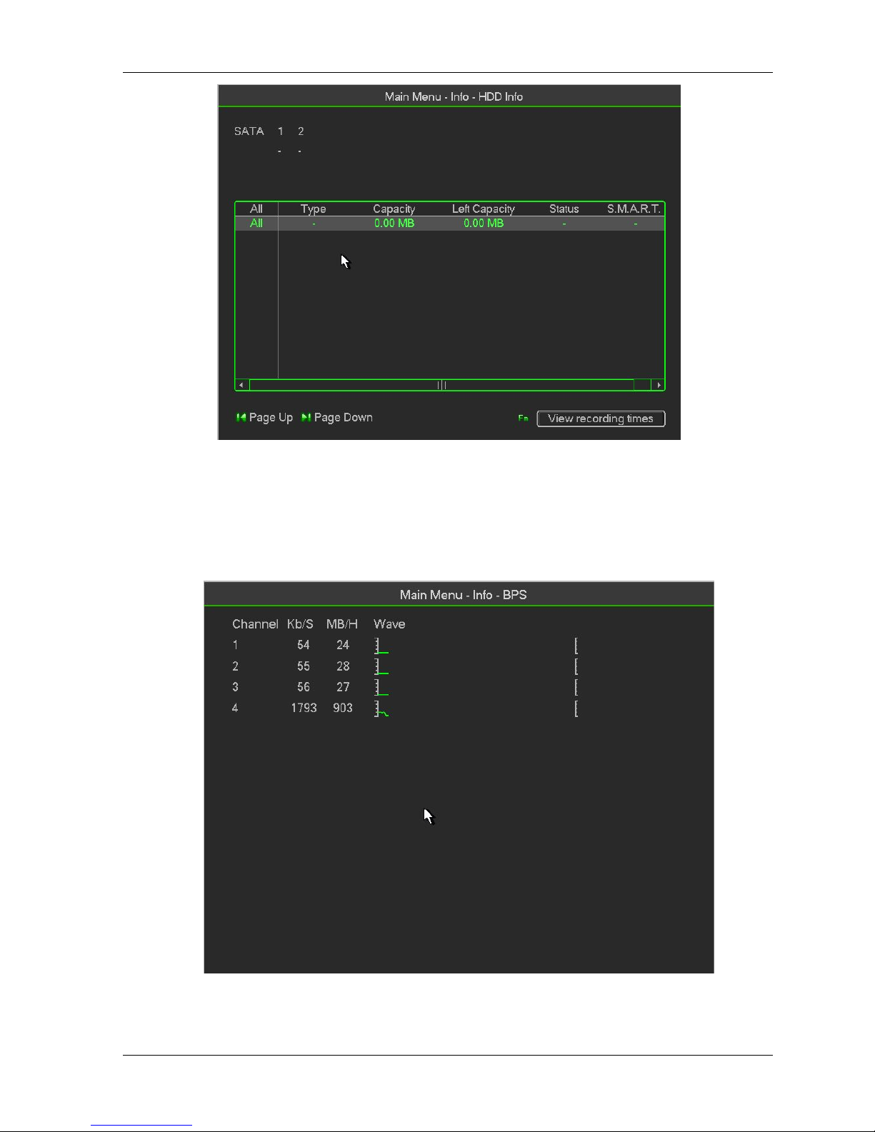
HDCVR
- 60 -
Figure 3- 57
Double click one HDD information; you can see the HDD SMART information
BPS
Here is for you to view current video data stream (KB/s), resolution and
etc.
Figure 3- 58
Page 61
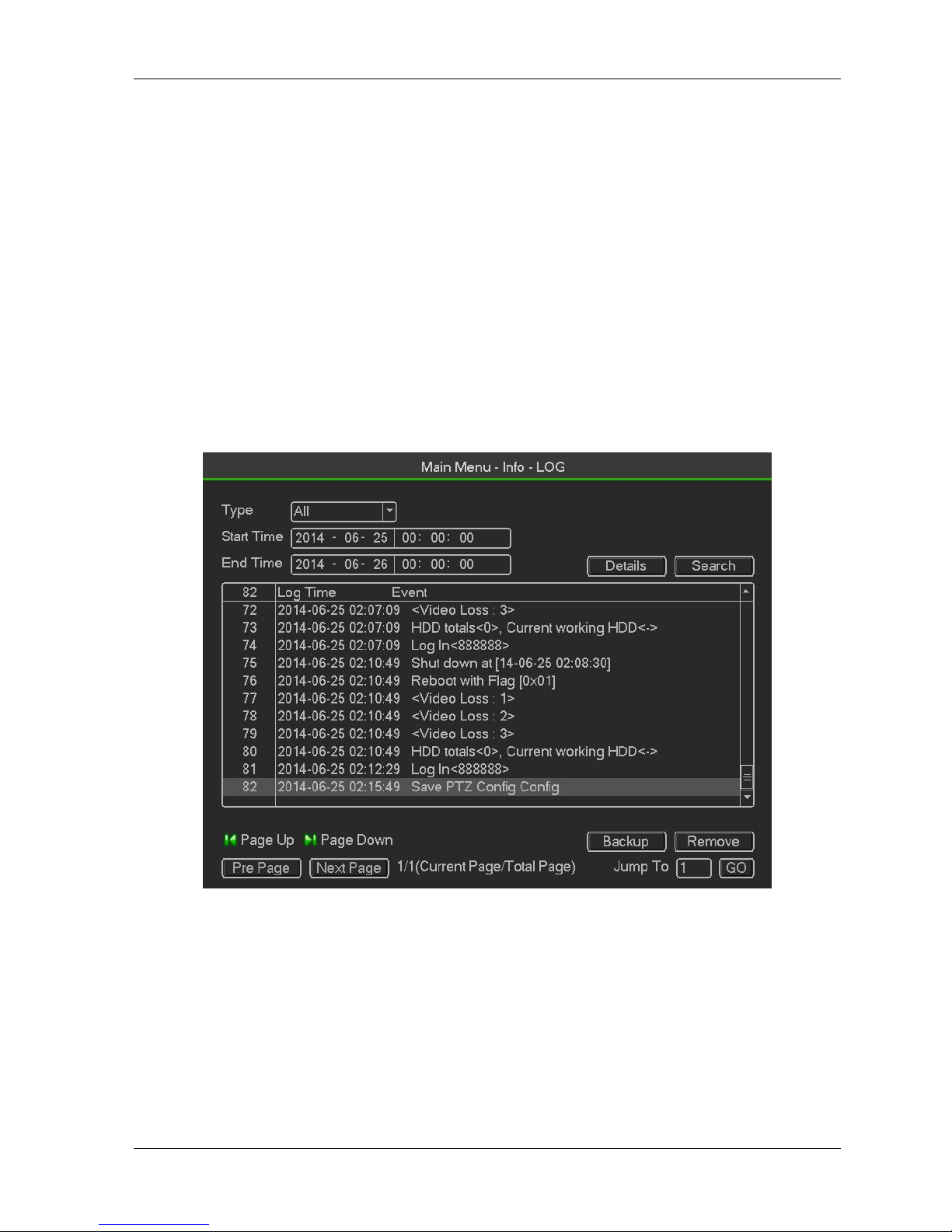
HDCVR
- 61 -
Log
Here is for you to view system log file. System lists the following informationLog types include system
operation, configuration operation, data management, alarm event, recordoperation, account manager, log
clear, file operation and etc. It optimized reboot log. There are onlythree types: normal reboot, abnormal
reboot and protection reboot. 0x02、0x03、0x04 is included in theprotection reboot type.
Start time/end time: Pleased select start time and end time, then click search button. You can viewthe log
files in a list. System max displays 100 logs in one page. It can max save 1024 log files.Please use page
up/down button on the interface or the front panel to view more.
Backup: Please select a folder you want to save; you can click the backup button to save the logfiles.
After the backup, you can see there is a folder named Log_time on the backup path. Double
click the folder, you can see the log file
Details: Click the Details button or double click the log item, you can view the detailed information. Here
you can use rolling bar to view information, or you can use Page up/Pagedown to view other log
information.
Figure 3- 59
Select an item on the list and then click the Details button or double click the log item, you can view
thedetailed information such as log time, log type, log user, IP address and etc
Page 62
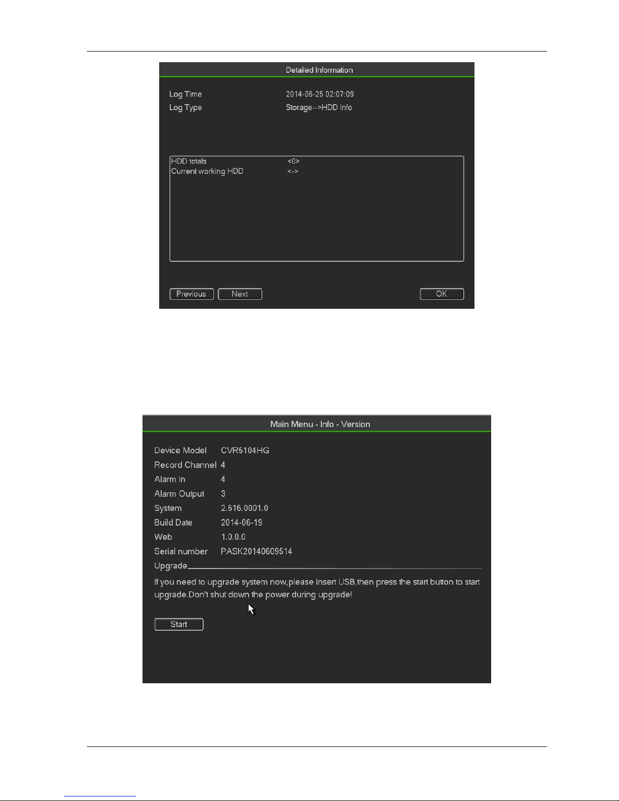
HDCVR
- 62 -
Figure 3- 60
Version
Here is for you to view some version information such as version number, built date, serial number
andetc
Figure 3- 61
Page 63
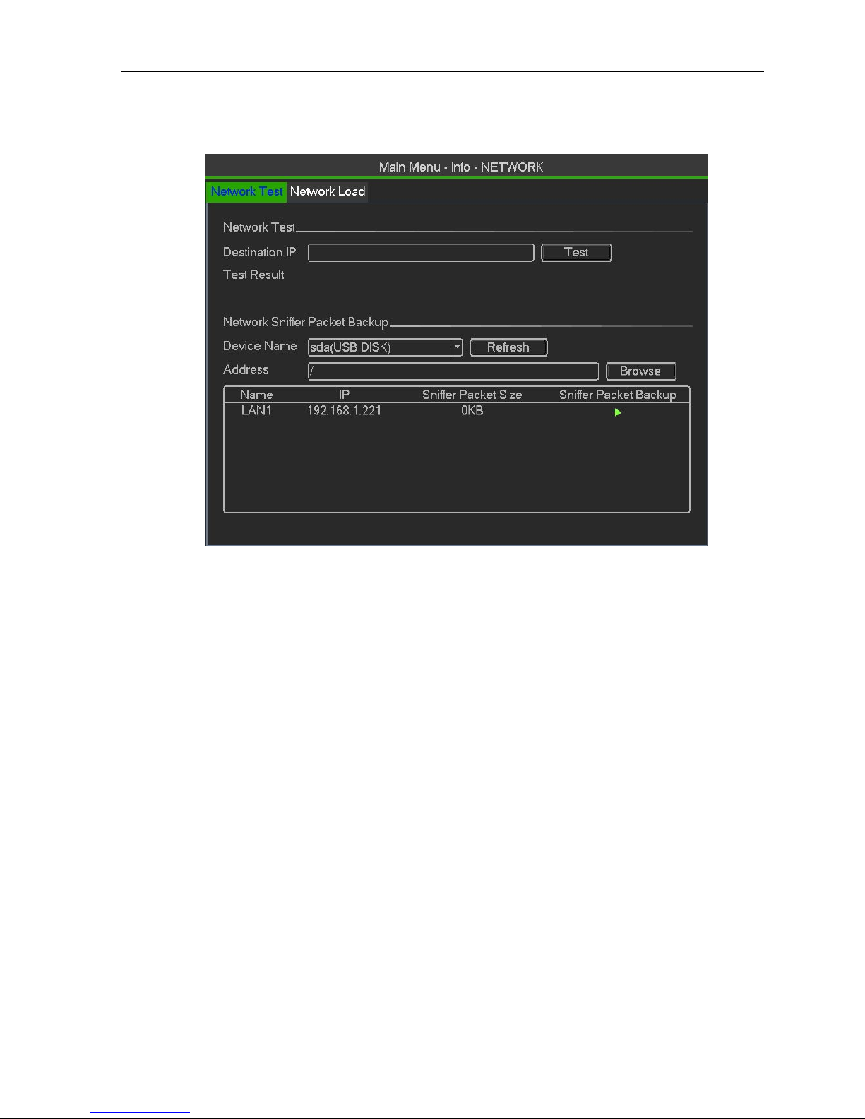
HDCVR
- 63 -
Network
Network Test
Figure 3- 62
Network test interface is shown。
Destination IP: Please input valid IPV4 address or domain name.
Test: Click it to test the connection with the destination IP address. The test results can
displayaverage delay and packet loss rate and you can also view the network status as OK, bad,
noconnection and etc
Network Sniffer backup: Please insert USB2.0 device and click the Refresh button, you can view
thedevice on the following column. You can use the dropdown list to select peripheral device.
ClickBrowse button to select the snap path. The steps here are same as preview backup operation.
You can view all connected network adapter names (including Ethernet, PPPoE, WIFI, and 3G), you canclick
the buttonon the right panel to begin Sniffer. Click the grey stop button to stop. Please note.system can not
Sniffer several network adapters at the same time.After Sniffer began, you can exit to implement
corresponding network operation such as login WEBmonitor. Please go back to Sniffer interface to clickstop
Sniffer. System can save the packets to thespecified path. The file is named after “Network adapter
name+time”. You can use software such asWireshark to open the packets on the PC for the professional
engineer to solve complicated problems.
Network Load
Network load is shown as in Figure 4-44. Here you can view the follow statistics of the device networkadapter.
Page 64

HDCVR
- 64 -
Figure 3- 63
Here you can view information of all connected network adapters. The connection status is shown asoffline if
connection is disconnected. Click one network adapter, you can view the flow statistics such assend rate and
receive rate at the top panel
3.3.5 Advanced
You can see HDD Manager,Account,Oline User,Auto Maintain,Text Overlay,Default,Config backup.
Figure 3- 64
Page 65
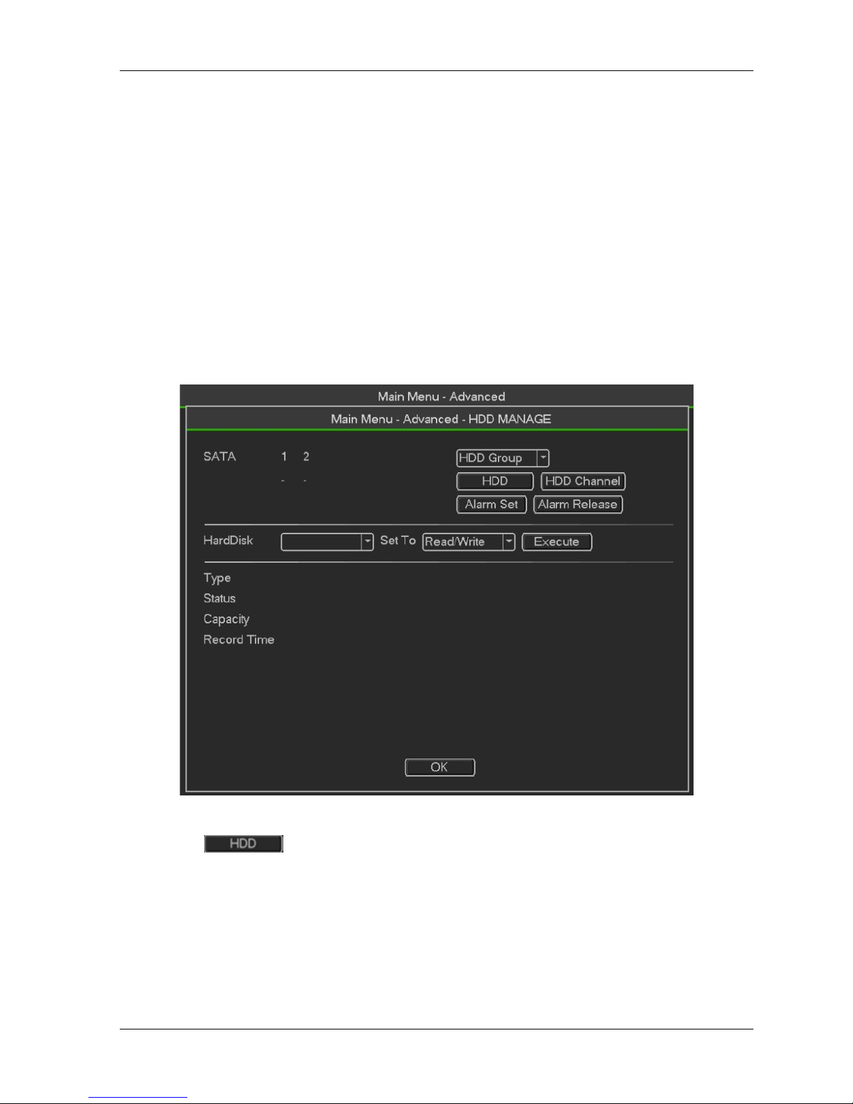
HDCVR
- 65 -
HDD Manager
Here is to list hard disk type, total space, free space, video start time and status.
SATA: 1 here means system max supports 1 HDD. ○ means current HDD is normal. X means there
is error. - means there is no HDD. If disk is damaged, system shows as “?”. Please remove the
broken hard disk before you add a new one.
SN: You can view the HDD amount the device connected to. ﹡ means the second HDD is current
working HDD.
Type: The corresponding HDD properties.
Total space: The HDD total capacity.
Free space: The HDD free capacity.
Status: HDD can work properly or not.
SMART: Display HDD information
Figure 3- 65
Double click ,Set HDD Group.
Page 66

HDCVR
- 66 -
Figure 3- 66
Double click ,Set HDD Channel.
Figure 3- 67
Account
Here is for you to implement account management.
Add new user
Modify user
Add group
Modify group
Modify password
For account management please note:
For the user account name and the user group, the string max length is 6-byte. The backspace infront of
or at the back of the string is invalid. There can be backspace in the middle. The stringincludes the valid
character, letter, number, underline, subtraction sign, and dot.
The default user amount is 64 and the default group amount is 20. System account adopts
two-levelmanagement: group and user. No limit to group or user amount.
Page 67

HDCVR
- 67 -
For group or user management, there are two levels: admin and user.
The user name and group name can consist of eight bytes. One name can only be used once.
There are four default users: admin/888888/666666 and hidden user “default”. Except user 6666,
other users have administrator right.
Hidden user “default” is for system interior use only and can not be deleted. When there is no loginuser,
hidden user “default” automatically login. You can set some rights such as monitor for thisuser so that you
can view some channel view without login.
One user should belong to one group. User right can not exceed group right.
About reusable function: this function allows multiple users use the same account to login.
About user account and MAC. When you add a new user, you can input the MAC address of currentuser.
Only the user of the same MAC address can access the device remotely.(MAC address is forthe device
of the same LAN.) If you leave MAC address item in blank when you add a new user, theuser of any MAC
address can access the device remotely. You can set or change MAC addresswhen you add or modify a
user. The MAC address function is also valid for PSS login. Please notecurrent function does not
support IPV6.
After all the setups please click save button, system goes back to the previous menu
Figure 3- 68
Add/Modify User
Page 68

HDCVR
- 68 -
Figure3-94
Click add user button in Figure 3-93 , the interface is shown as in Figure 3-94.
Please input the user name, password, select the group it belongs to from the dropdown list.
Then you can check the corresponding rights for current user.
For convenient user management, usually we recommend the general user right is lower than the admin
account.
When you create a new user, you can input the corresponding MAC address of current user. If you
leavethis item in blank, any MAC address user can share this user account to login. Please note
systemneeds to check the validity of MAC. Only the 12-digit 0-f format address can pass the validity
verification。
System only saves small character even you input capitalized one. You can see the correspondingprompt
if there is any illegal input.
Add/Modify Group
Page 69

HDCVR
- 69 -
Figure4- 2
Click add group button in Figure 4-65 , the interface is shown as below. See Figure 4-.68 Here you can
input group name and then input some memo information if necessary.
There are total 98 rights such as control panel, shut down, real-time monitor, playback, record, recordfile
backup, PTZ, user account, system information view, alarm input/output setup, system setup, logview,
clear log, upgrade system, control device and etc.
Online Users
Here is for you to manage online users.
You can disconnect one user or block one user if you have proper system right. Max disconnectionsetup
is 65535 seconds.
System detects there is any newly added or deleted user in each five seconds and refresh the
listautomatically.
Figure 3- 69
Auto Maintain
Here you can set auto-reboot time and auto-delete old files setup. You can set to delete the files for
thespecified days
Page 70

HDCVR
- 70 -
Figure 3- 70
ATM/POS
The ATM/POS function is for financial areas. It includes Sniffer, information analysis and title overlay
function. The Sniffer mode is network.
The network type interface is shown as below.
Here we take the ATM/POS protocol to continue.
There are two types: with or without the protocol according to client’s requirements.
With the protocol
For ATM/POS with the protocol, you just need to set the source IP, destination IP (sometimes you need
to input corresponding port number).
Figure 3- 71
Without the protocol
For the ATM/POS without the protocol, the interface is shown.
Source IP refers to host IP address that sends out information (usually it is the device host.)
Page 71
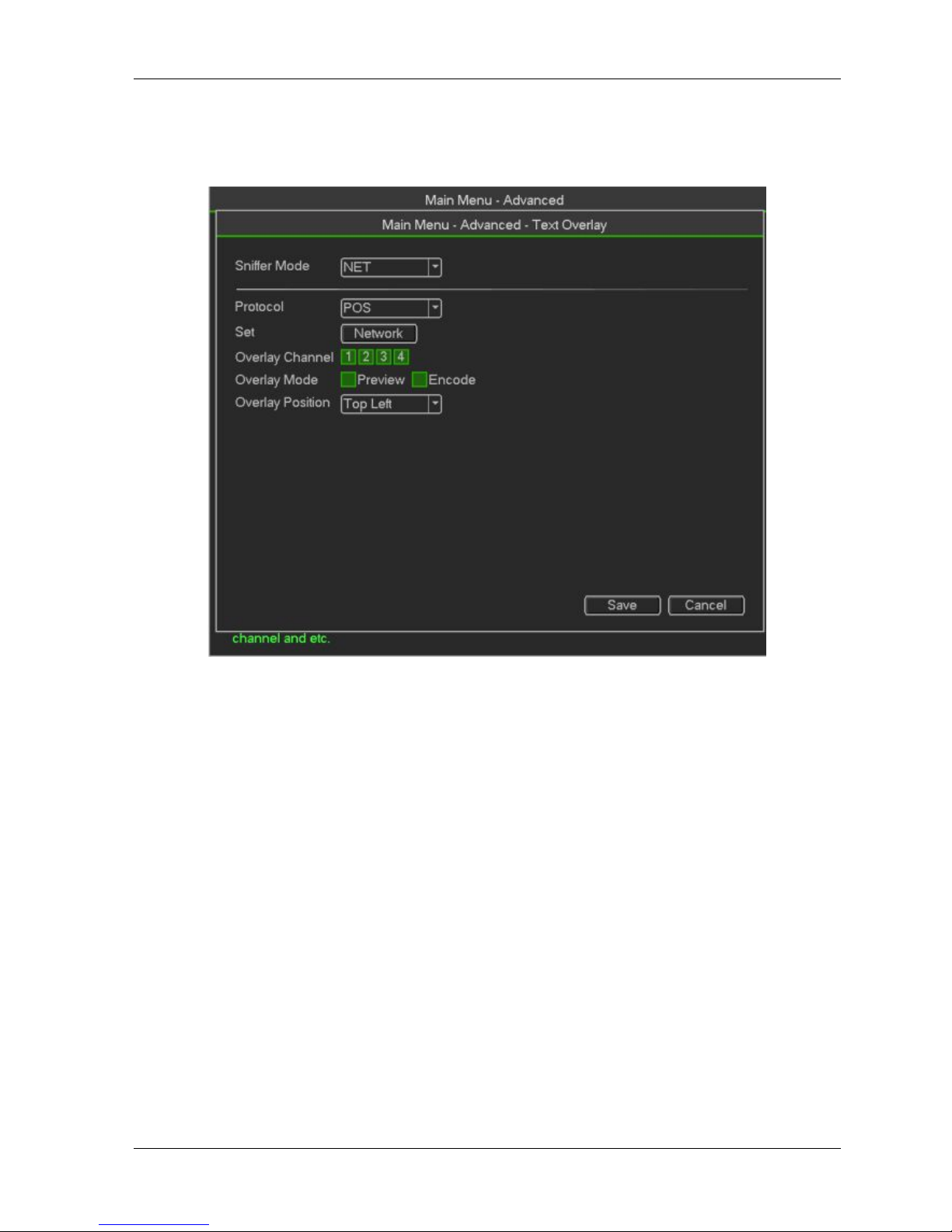
HDCVR
- 71 -
Destination IP refers to other systems that receive information.
Usually you do not need to set source port and target port.
There are total four groups IP. The record channel applies to one group (optional) only.
Six frame ID groups verification can guarantee information validity and legal.
Figure 3- 72
Default
Click default icon, system pops up a dialogue box. You can highlighto restore default factory setup.
Camera
Network
Event
Storage
System
Please highlight iconto select the corresponding function.
After all the setups please click save button, system goes back to the previous menu.
Warning!
System menu color, language, time display mode, video format, IP address, user account will notmaintain
previous setup after default operation!
Page 72

HDCVR
- 72 -
Figure 3- 73
Backup
DVR support CD-RW, DVD burner, USB device backup, network download and eSATA. Here
weintroduce USB, eSATA backup. You can refer to Chapter 5 Web Operation for network
downloadbackup operation。
Figure 3- 74
Click backup button, you can see an interface is shown as in Figure 4-32. Here is for you to viewdevices
Page 73

HDCVR
- 73 -
information.
You can view backup device name and its total space and free space. The device includes CD -RW,DVD
burner, USB device, flash disk, eSATA backup
Select backup device and then set channel, file start time and end time.
Click add button, system begins search. All matched files are listed below. System
automaticallycalculates the capacity needed and remained.
System only backup files with a √ before channel name. You can use Fn or cancel button to delete
√ after file serial number
Click Start button, system begins copy. At the same time, the backup button becomes stop button.
You can view the remaining time and process bar at the left bottom
When the system completes backup, you can see a dialogue box prompting successful backup
File format: Click the file format; you can see there are two options: DAV/ASF
The file name format usually is: Channel number+Record type+Time. In the file name, the YDM
format is Y+M+D+H+M+S. File extension name is .dav
Tips:
During backup process, you can click ESC to exit current interface for other operation. The systemwill not
terminate backup process.
Note:
When you click stop button during the burning process, the stop function becomes activatedimmediately.
For example, if there are ten files, when you click stop system just backup five files,system only save the
previous 5 files in the device (But you can view ten file names).
Digital
Add the IPC
This function is for adding IPC Camera.You can select the channel for IPC ,just as follow.
Then exit the menu and return to the preview screen,move the mouse onto the channel you selected,
Then you will see
click
,you will get into setting screen as follow.
Page 74
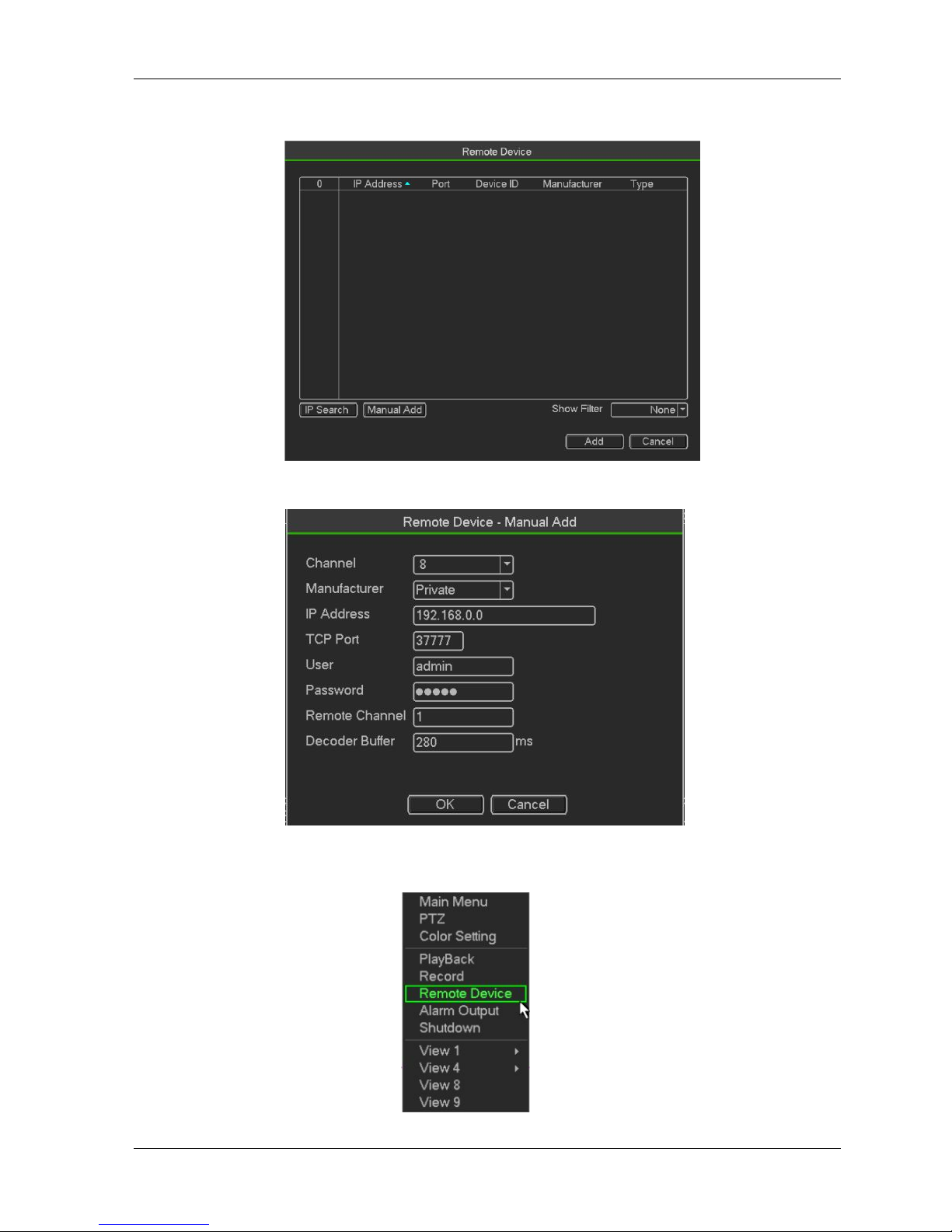
HDCVR
- 74 -
You have two methods to add IPC,IP search and Manual add ,as Manual add for example. Click Manual
add,you will set IPC information as follow .You can select ONFI protocol.Click OK to save the information.
Change the IPC
Move the mouse onto the channel you want to change.Right click the mouse,select Remot Device,and
you will see the setting screen.You can change/add/delete IPC information.
Page 75

HDCVR
- 75 -
3.3.6
Shut Down
select Shut Down, you can go to the following interface..
There are three options: Shutdown/logout/reboot.
For the user who does not have the shut down right, please input corresponding password to shut down
Figure 3- 75
Page 76

HDCVR WEB
- 76 -
4. WEB OPERATION
Slightly difference may be found in the interface due to different series.
4.1 Network Connection
Before web client operation, please check the following items
Network connection is right.
DVR and PC network setup is right. Please refer to network setup(main menu->Setting->Network)
Use order ping ***.***.***.***(* DVR IP address) to check connection is OK or not. Usually the return
TTL value should be less than 255.
Current series product supports various browsers such as Safari, fire fox browser, Google browser.
Device supports multiple-channel monitor, PTZ control, DVR parameter setup on the Apple PC.
4.2 Login
Open IE and input DVR address in the address column. For example, if your DVR IP is 10.10.3.16,
thenplease input http:// 10.10.3.16 in IE address column.
System pops up warning information to ask you whether install control or not. Please click Install
button.See Figure 4-1.
Figure4- 3
After installation, the interface is shown as below. See Figure 5-2.
Please input your user name and password.
Default factory name is admin and password is admin.
Note: For security reasons, please modify your password after you first login.
Page 77
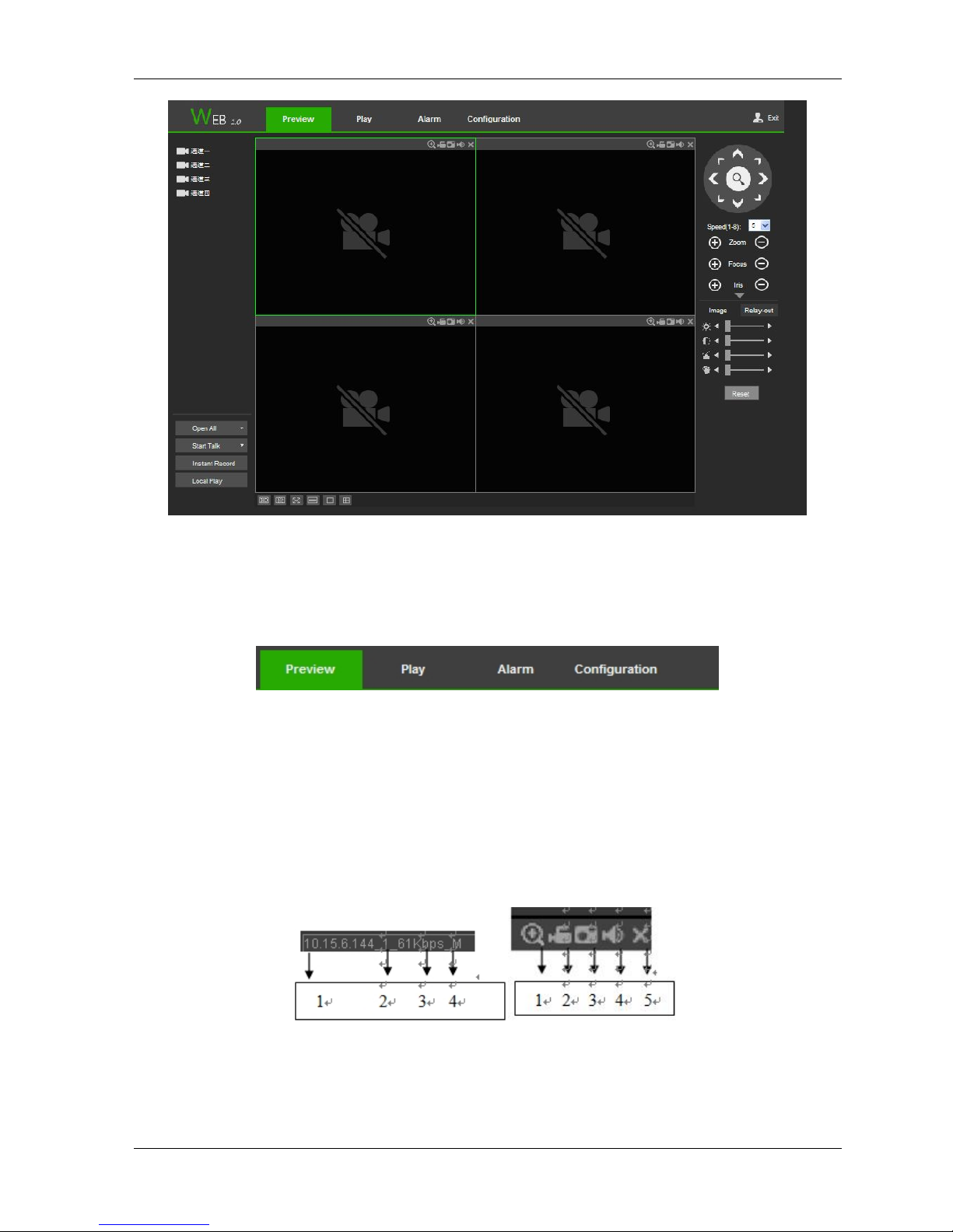
HDCVR WEB
- 77 -
Figure4- 4
4.3 System menu
Figure4- 5
4.3.1 Live
In section 2, left click the channel name you want to view, you can see the corresponding video incurrent
window.On the top left corner, you can view device IP (10.15.6.144), channel number (1), network monitor bit
stream (61Kbps) and stream type: M (Main stream)/S (Sub stream).
Figure4- 6
On the top right corer, there are six unction buttons
1: Digital zoom: Click this button and then left drag the mouse in the zone to zoom in. right clickmouse
system restores original status.
2: Local record. When you click local record button, the system begins recording and this buttonbecomes
Page 78
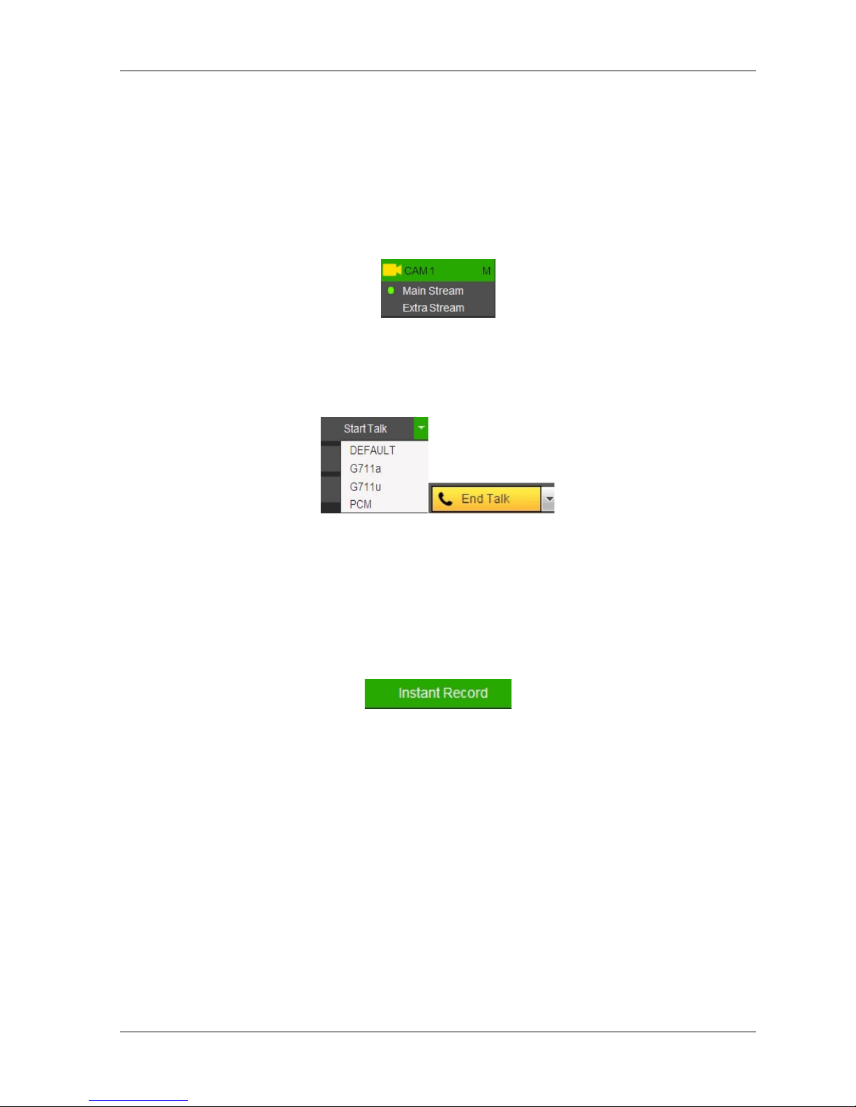
HDCVR WEB
- 78 -
highlighted. You can go to system folder RecordDownload to view the recorded file.
3: Snapshot picture. You can snapshoot important video. All images are memorized in system clientfolder
PictureDownload (default).
4: Audio :Turn on or off audio.(It has no relationship with system audio setup )
5: Close video.
There are channel number and one button: Start all. Start all button is to enable/disable,all-channel real-time
monitor. Click it the button becomes yellow.
Figure4- 7
4.3.2 Start dialogue button
Figure4- 8
You can click this button to enable audio talk. Click【▼】 to select bidirectional talk mode. There arefour
options: DEFAULT,G711a,G711u and PCM. After you enable the bidirectional talk, the Start talkbutton
becomes End Talk button and it becomes yellow
4.3.3 Instant record button
Figure4- 9
Click it, the button becomes yellow and system begins manualrecord. See Figure 4-7. Click it again, system
restores previous record mode
4.3.4 Local play button
The Web can playback the saved (Extension name is dav) files in the PC-end,Click local play button,
system pops up the following interface for you to select local play file.
Page 79
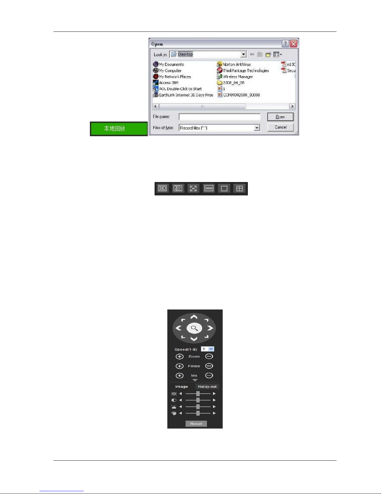
HDCVR WEB
- 79 -
Figure4- 10
4.3.5
Window change
Figure4- 11
From left to right, it is to set video quality, video latency, full screen, 1-window, 4-window.
。
4.3.6
PTZ control
Before PTZ operation, please make sure you have properly set PTZ protocol
There are eight direction keys. In the middle of the eight direction keys, there is a 3D intelligentpositioning
key.
Click 3D intelligent positioning key, system goes back to the single screen mode. Drag the mouse in
thescreen to adjust section size. It can realize PTZ automatically.
Please refer to the following sheet for PTZ setup information.
Figure4- 12
Page 80

HDCVR WEB
- 80 -
4.3.7 Image
Here you can adjust its brightness, contrast, hue and saturation. (Current channel border
becomesgreen).Or you can click Reset button to restore system default setup
Figure4- 13
Page 81

HDCVR WEB
- 81 -
4.4
Setup
4.4.1 Camera
Conditions
Here you can view device property information. The setups become valid immediately after you set. See
Figure 4-12.
Figure 4-12
Please refer to the following sheet for detailed information
Page 82

HDCVR WEB
- 82 -
.
Parameter
Function
Channel
Please select a channel from the dropdown list.
Period
It divides one day (24 hours) to two periods. You can set
different hue, brightness, and contrast for different periods.
Hue
It is to adjust monitor video brightness and darkness level. The
default value is 50.
The bigger the value is, the large the contrast between the
bright and dark section is and vice versa.
Brightness
It is to adjust monitor window brightness. The default value is
50.
The larger the number is , the bright the video is. When you
input the value here, the bright section and the dark section of
the video will be adjusted accordingly. You can use this
function when the whole video is too dark or too bright. Please
note the video may become hazy if the value is too high. The
value ranges from 0 to 100.The recommended value ranges
from 40 to 60.
Contrast
It is to adjust monitor window contrast. The value ranges from 0
to 100. The default value is 50.
The larger the number is, the higher the contrast is. You can
use this function when the whole video bright is OK but the
contrast is not proper. Please note the video may become hazy
if the value is too low. If this value is too high, the dark section
may lack brightness while the bright section may over
exposure .The recommended value ranges from 40 to 60.
Saturation
It is to adjust monitor window saturation. The value ranges from
0 to 100. The default value is 50.
The larger the number is, the strong the color is. This value has
no effect on the general brightness of the whole video. The
video color may become too strong if the value is too high. For
4.4.2 Encode
The encode interface is shown as below
Page 83

HDCVR WEB
- 83 -
Figure 4-13
Please refer to the following sheet for detailed information.
Parameter
Function
Channel
Please select a channel from the dropdown list.
Video enable
Check the box here to enable extra stream video. This item is
enabled by default.
Code stream
type
It includes main stream, motion stream and alarm stream. You
can select different encode frame rates form different recorded
events.
System supports active control frame function (ACF). It allows
you to record in different frame rates.
For example, you can use high frame rate to record important
events, record scheduled event in lower frame rate and it allows
you to set different frame rates for motion detection record and
alarm record.
Compression
The main bit stream supports H.264. The extra stream supports
H.264, MJPG.
Page 84

HDCVR WEB
- 84 -
Resolution
System supports various resolutions, you can select from the
dropdown list. Please note the option may vary due to different
series.
Frame Rate
PAL:1~25f/s;NTSC:1~30f/s.
Bit Rate
Main stream: You can set bit rate here to change video
quality. The large the bit rate is , the better the quality is.
Please refer to recommend bit rate for the detailed
information.
Extra stream: In CBR, the bit rate here is the max value.
In dynamic video, system needs to low frame rate or
video quality to guarantee the value. The value is null in
VBR mode.
Reference bit
rate
Recommended bit rate value according to the resolution and
frame rate you have set.
I Frame
Here you can set the P frame amount between two I frames.
The value ranges from 1 to 150. Default value is 50.
Recommended value is frame rate *2.
Audio source
Please select from the dropdown list. There are two
options: Normal/HDCVI. In the normal mode, the audio
signal comes from the Audio In. In the HDCVI mode,
the audio signal comes from the coaxial cable of the
camera.
Watermark
enable
This function allows you to verify the video is tampered
or not.
Here you can select watermark bit stream, watermark mode
and watermark character. Default character is DigitalCCTV. The
max length is 85-digit. The character can only include number,
character and underline.
Snapshot
Figure 4-14
Please refer to the following sheet for detailed information.
Parameter
Function
Snapshot type
There are two modes: Regular (schedule) and Trigger.
Regular snapshot is valid during the specified period you
set.
Trigger snapshot only is valid when motion detect alarm,
tampering alarm or local activation alarm occurs.
Image size
It is the same with the resolution of the main stream.
Page 85

HDCVR WEB
- 85 -
Quality
It is to set the image quality. There are six levels.
Interval
It is to set snapshot frequency. The value ranges from 1s to 7s.
Or you can set customized value. The max setup is
3600s/picture.
Copy
Click it; you can copy current channel setup to other
channel(s).
Parameter
Function
Cover-area
Check Preview or Monitor first.
Click Set button, you can privacy mask the specified video in
the preview or monitor video.
System max supports 4 privacy mask zones.
Time Title
You can enable this function so that system overlays time
information in video window.
You can use the mouse to drag the time title position.
You can view time title on the live video of the WEB or the
playback video.
Channel Title
You can enable this function so that system overlays channel
information in video window.
You can use the mouse to drag the channel title position.
You can view channel title on the live video of the WEB or the
playback video.
Video Overlay
he video overlay interface is shown
Figure 4-15
Please refer to the following sheet for detailed information
Path
The storage path interface is shown
Here you can set snap image saved pathand the record storage path.The default setup is C:\PictureDownload
Page 86

HDCVR WEB
- 86 -
and C:\RecordDownload.Please click the Save button to save current setup.
Figure 4-16
Channel Name
Here you can set channel name. See Figure 4-17
Figure 4-17
4.4.3 Network
TCP/IP
The TCP/IP interface is shown as in Figure 4-18
Please refer to the following sheet for detailed information.
Parameter
Function
Mode
There are two modes: static mode and the DHCP mode.
The IP/submask/gateway are null when you select the
Page 87

HDCVR WEB
- 87 -
DHCP mode to auto search the IP.
If you select the static mode, you need to set the
IP/submask/gateway manually.
If you select the DHCP mode, you can view the
IP/submask/gateway from the DHCP.
If you switch from the DHCP mode to the static mode, you
need to reset the IP parameters.
Besides, IP/submask/gateway and DHCP are read-only
when the PPPoE dial is OK.
Mac Address
It is to display host Mac address.
IP Version
It is to select IP version. IPV4 or IPV6.
You can access the IP address of these two versions.
IP Address
Please use the keyboard to input the corresponding number to
modify the IP address and then set the corresponding subnet
mask and the default gateway.
Preferred DNS
DNS IP address.
Alternate DNS
Alternate DNS IP address.
For the IP address of IPv6 version, default gateway, preferred DNS and
alternate DNS, the input value shall be 128-digit. It shall not be left in blank.
LAN load
System can process the downloaded data first if you
enable this function. The download speed is 1.5X or
2.0X of the normal speed.
Connection
The connection interface is shown as in Figure 4-19.
Figure 4-19
Please refer to the following sheet for detailed information.
Parameter
Function
Max connection
It is the max Web connection for the same device. The value
ranges from 1 to 120. The default setup is 120.
TCP port
The default value is 37777. You can input the actual port
number if necessary.
UDP port
The default value is 37778. You can input the actual port
number if necessary.
Page 88

HDCVR WEB
- 88 -
HTTP port
The default value is 80. You can input the actual port number if
necessary.
HTTPS
The default value is 443. You can input the actual port number
if necessary.
RTSP port
The default value is 554.
WIFI
Please note this function is for the device of WIFI module.
The WIFI interface is shown as in Figure 4-20.
Figure 4-20
Please check the box to enable WIFI function and then click the Search SSID button. Now you can view
all the wireless network information in the following list. Double click a name to connect to it. Click
Refresh button, you can view latest connection status.
3G
CDMA/GPRS
The CDMA/GPRS interface is shown as in Figure 4-21.
Figure 4-21
Please refer to the following sheet for detailed information.
Page 89

HDCVR WEB
- 89 -
Parameter
Function
WLAN type
Here you can select 3G network type to distinguish
the 3G
module from different ISP. The types include
WCDMA,
CDMA1x and etc.
APN/Dial No.
Here is the important parameter of PPP.
Authorization
It includes PAP,CHAP,NO_AUTH.
Pulse interval
It is to set time to end 3G connection after you close
extra
stream monitor. For example, if you input 60 here,
system ends
3G connection after you close extra stream monitor
60
seconds.
Mobile
The mobile setup interface is shown as in Figure 4-22.
Here you can activate or turn off the 3G connected phone or mobile phone, or the phone you set to get
alarm message.
Figure 4-22
PPPoE
The PPPoE interface is shown as in Figure 4-23
Input the PPPoE user name and password you get from the IPS (internet service provider) and enable
PPPoE function. Please save current setup and then reboot the device to get the setup activated.
Device connects to the internet via PPPoE after reboot. You can get the IP address in the WAN from the
IP address column.
Please note, you need to use previous IP address in the LAN to login the device. Please go to the
IP address item to via the device current device information. You can access the client-end via
this new address.
Page 90
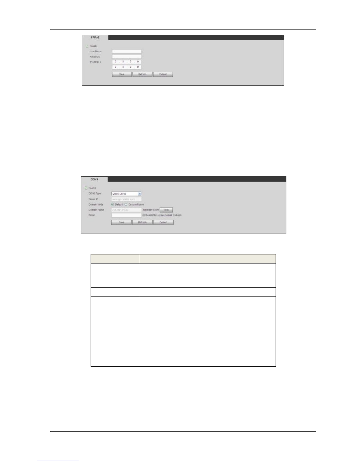
HDCVR WEB
- 90 -
Figure 4-23
DDNS
The DDNS interface is shown as in Figure 4-24.
The DDNS is to set to connect the various servers so that you can access the system via the server.
Please go to the corresponding service website to apply a domain name and then access the system via
the domain. It works even your IP address has changed.
Please select DDNS from the dropdown list (Multiple choices). Before you use this function, please
make sure your purchased device support current function.
Figure 4-24
Please refer to the following sheet for detailed information.
Parameter
Function
Server Type
You can select DDNS protocol from the dropdown
list and then
enable DDNS function.
Server IP
DDNS server IP address
Server Port
DDNS server port.
Domain Name
Your self-defined domain name.
User
The user name you input to log in the server.
Password
The password you input to log in the server.
Update period
Device sends out alive signal to the server regularly.
You can set interval value between the device and
DDNS server
here.
Quick DDNS and Client-end Introduction
1) Background Introduction
Device IP is not fixed if you use ADSL to login the network. The DDNS function allows you to access the
DVR via the registered domain name. Besides the general DDNS, the quick DDNS works with the
device from the manufacturer so that it can add the extension function.
Page 91

HDCVR WEB
- 91 -
2) Function Introduction
The quick DDNS client has the same function as other DDNS client end. It realizes the bonding of the
domain name and the IP address. Right now, current DDNS server is for our own devices only. You
need to refresh the bonding relationship of the domain and the IP regularly. There is no user name,
password or the ID registration on the server. At the same time, each device has a default domain name
(Generated by MAC address) for your option. You can also use customized valid domain name (has not
registered.).
3) Operation
Before you use Quick DDNS, you need to enable this service and set proper server address, port valueand
domain name
Server address:www.quickddns.com
Port number:80
Domain name:There are two modes: Default domain name and customized domain nameExcept default
domain name registration, you can also use customized domain name (You can inputyour self-defined
domain name.) After successful registration, you can use domain name to logininstalled of the device IP.
User name: It is optional. You can input your commonly used email address.
Important
Do not register frequently. The interval between two registrations shall be more than 60 seconds.Too
many registration requests may result in server attack.
System may take back the domain name that is idle for one year. You can get a notification emailbefore
the cancel operation if your email address setup is OK.
IP filter
The IP filter interface is shown as in Figure 4-25
After you enabled trusted sites function, only the IP listed below can access current DVR.
If you enable blocked sites function, the following listed IP addresses can not access current DVR.
Figur 4-25
Email
The email interface is shown as in Figure 4-26.
Page 92
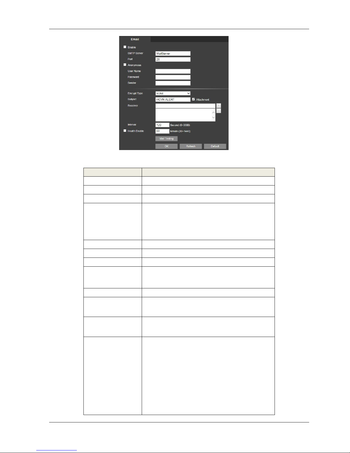
HDCVR WEB
- 92 -
Figure 4-26
Please refer to the following sheet for detailed information.
Parameter
Function
Enable
Please check the box here to enable email function.
SMTP Server
Input server address and then enable this function.
Port
Default value is 25. You can modify it if necessary.
Anonymity
For the server supports the anonymity function. You
can auto
login anonymously. You do not need to input the
user name.
password and the sender information.
User Name
The user name of the sender email account.
Password
The password of sender email account.
Sender
Sender email address.
Authentication
(Encryption
mode)
You can select SSL or none.
Subject
Input email subject here.
Attachment
System can send out the email of the snapshot
picture once
you check the box here.
Receiver
Input receiver email address here. Max three
addresses.
It supports SSL, TLS email box.
Interval
The send interval ranges from 0 to 3600 seconds. 0
means
there is no interval.
Please note system will not send out the email
immediately
when the alarm occurs. When the alarm, motion
detection or
the abnormity event activates the email, system
sends out the
email according to the interval you specified here.
This
function is very useful when there are too many
Page 93
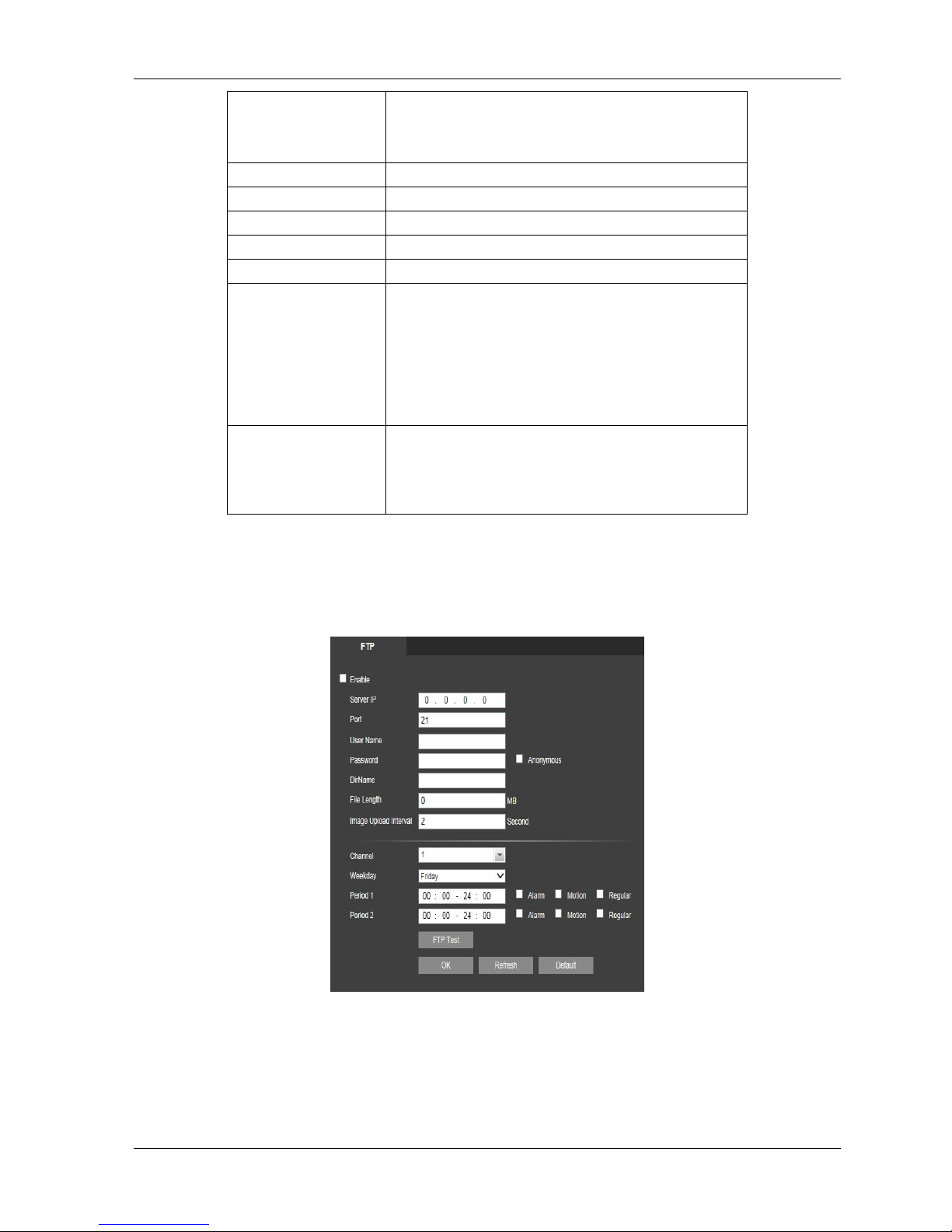
HDCVR WEB
- 93 -
emails
activated by the abnormity events, which may result
in heavy
load for the email server.
Health mail
Please check the box here to enable this function.
Parameter
Function
Enable
Please check the box here to enable email function.
SMTP Server
Input server address and then enable this function.
Health mail enable
Please check the box here to enable this function.
Update period
(interval)
This function allows the system to send out the test
email to
check the connection is OK or not.
Please check the box to enable this function and
then set the
corresponding interval.
System can send out the email regularly as you set
here.
Email test
The system will automatically sent out a email once
to test the
connection is OK or not .Before the email test,
please save
the email setup information.
FTP
The FTP interface is shown as in Figure 4-27.
It is to set FTP IP, port and etc for remote storage.
Figure 4-27
Page 94

HDCVR WEB
- 94 -
UPnP
It allows you to establish the mapping relationship between the LAN and the public network.
Here you can also add, modify or remove UPnP item. See Figure 4-28.
In the Windows OS, From Start->Control Panel->Add or remove programs. Click the
“Add/RemoveWindows Components” and then select the “Network Services” from the Windows
ComponentsWizard.
Click the Details button and then check the “Internet Gateway Device Discovery and Control client”and
“UPnP User Interface”. Please click OK to begin installation.
Enable UPnP from the Web. If your UPnP is enabled in the Windows OS, the DVR can auto detectit via
the “My Network Places”
Figure 4-28
SNMP
The SNMP interface is shown as in Figure 4-29.
The SNMP allows the communication between the network management work station software and the
proxy of the managed device. It is reserved for the 3rd party to develop.
Figure 4-29
Please refer to the following sheet for detailed information.
SNMP Port
The listening port of the proxy program of the
device. It is aUDP port not a TCP port. The value
ranges from 1 to 65535.The default value is 161
Page 95

HDCVR WEB
- 95 -
Read Community
It is a string. It is a command between the manage
processand the proxy process. It defined the
authentication, accesscontrol and the management
relationship between one proxyand one group of
the managers. Please make sure the deviceand the
proxy are the same.The read community will read
all the objects the SNMPsupported in the specified
name. The default setup is public.
Write Community
It is a string. It is a command between the manage
processand the proxy process. It defined the
authentication, accesscontrol and the management
relationship between one proxyand one group of
the managers. Please make sure the deviceand the
proxy are the same.The read community will
read/write/access all the objects the
SNMP Port
The listening port of the proxy program of the
device. It is aUDP port not a TCP port. The value
ranges from 1 to 65535.The default value is
161SNMP supported in the specified name. The
default setup iswrite.
Trap address
The destination address of the Trap information
from theproxy program of the device.
Trap port
The destination port of the Trap information from
the proxyprogram of the device. It is for the gateway
device and theclient-end PC in the LAN to
exchange the information. It is anon-protocol
connection port. It has no effect on the network
applications. It is a UDP port not TCP port. The
value rangesfrom 1 to 165535. The default value is
162.
SNMP version
Check V1, system only processes the information
of V1.
Check V2, system only processes the information
of V2.
Multicast
The multicast interface is shown as in Figure 4-30.
Multicast is a transmission mode of data packet. When there is multiple-host to receive the same data
packet, multiple-cast is the best option to reduce the broad width and the CPU load. The source host
can just send out one data to transit. This function also depends on the relationship of the group
member and group of the outer.
Figure 4-30
Page 96

HDCVR WEB
- 96 -
Auto Register
The auto register interface is shown as below. See Figure 4-31.
This function allows the device to auto register to the proxy you specified. In this way, you can use the
client-end to access the DVR and etc via the proxy. Here the proxy has a switch function. In the network
service, device supports the server address of IPv4 or domain.
Please follow the steps listed below to use this function.
Please set proxy server address, port, and sub-device name at the device-end. Please enable the auto
register function, the device can auto register to the proxy server.
Figure 4-31
Alarm Centre
The alarm centre interface is shown as below. See Figure 4-32
This interface is reserved for you to develop. System can upload alarm signal to the alarm centre whenlocal
alarm occurs.
Before you use alarm centre, please set server IP, port and etc. When an alarm occurs, system cansend out
data as the protocol defined, so the client-end can get the data.
Figure4-32
HTTPS
In this interface, you can set to make sure the PC can successfully login via the HTTPS. It is toguarantee
communication data security. The reliable and stable technology can secure the userinformation security and
device safety. See Figure 4-33
Note:
You need to implement server certificate again if you have changed device IP.
You need to download root certificate if it is your first time to use HTTPS on current PC
Page 97

HDCVR WEB
- 97 -
Figure4-33
Create Server Certificate
If it is your first time to use this function, please follow the steps listed below.
In Figure 5-36, click button, input country name, state name and etc. ClickCreate
button. See Figure 4-34
Note:
Please make sure the IP or domain information is the same as your device IP or domain name.
Figure 4-34
You can see the corresponding prompt. See Figure 4-35. Now the server certificate is successfullycreated.
Figure 4-35
Download root certificate
In Figure 5-33, click button, system pops up a dialogue box. See Figure 4-36
Figure 4-36
Click Open button, you can go to the following interface. See Figure 4-37.
Page 98

HDCVR WEB
- 98 -
Figure4-37
Click Install certificate button, you can go to certificate wizard. See Figure 4-38
Figure 4-38
Click Next button to continue. Now you can select a location for the certificate. See Figure 4-39.
Figure4-39
Click Next button, you can see the certificate import process is complete. See Figure 4-40.
Page 99

HDCVR WEB
- 99 -
Figure 4-40
Click Finish button, you can see system pops up a security warning dialogue box. See Figure 4-41.
Figure 4-41
Click Yes button, system pops up the following dialogue box, you can see the certificate download is
complete. See Figure 4-42.
Figure4-42
View and set HTTPS port
From Setup->Network->Connection, you can see the following interface. See Figure 4-43.
You can see HTTPS default value is 443.
Figure 4-43
Login
Open the browser and then input https://xx.xx.xx.xx:port.
xx.xx.xx.xx: is your device IP or domain mane.
Page 100

HDCVR WEB
- 100 -
Port is your HTTPS port. If you are using default HTTPS value 443, you do not need to add port
information here. You can input https://xx.xx.xx.xx to access.
Now you can see the login interface if your setup is right.
4.4.4 Event
Video detect
1. Motion Detect
The motion detect interface is shown as in
Figure 4-44.
Figure4-45
 Loading...