

Page 1

HDC-HFW3200C Quick Start Guide
Version 1.0.1
Page 2

i
Welcome
Thank you for purchasing our digital camera!
This quick start guide is designed to be a reference tool for your system.
Please keep this start guide well for future reference.
Please open the accessory bag to check the items one by one in accordance with the list below.
Contact your local retailer ASAP if something is missing or damaged in the bag.
Before your operation please read the following instructions carefully.
1.Electrical safety
All installation and operation here should conform to your local electrical safety codes.
The power shall conform to the requirement in the SELV (Safety Extra Low Voltage) and the Limited
power source is rated 12V DC or 24V AC in the IEC60950-1. (Refer to general introduction) Please
note: Do not connect two power supplying sources to the device at the same time; it may result
in device damage!
We assume no liability or responsibility for all the fires or electrical shock caused by improper handling
or installation.
We are not liable for any problems caused by unauthorized modification or attempted repair.
2.Transportation security
Heavy stress, violent vibration or water splash are not allowed during transportation, storage and
installation.
3.Installation
Do not apply power to the camera before completing installation.
Please install the proper power cut-off device during the installation connection.
Always follow the instruction guide the manufacturer recommended.
4.Qualified engineers needed
All the examination and repair work should be done by the qualified service engineers.
We are not liable for any problems caused by unauthorized modifications or attempted repair.
5.Environment
This series digital camera should be installed in a cool, dry place away from direct sunlight, inflammable,
explosive substances and etc.
Please keep it away from the electromagnetic radiation object and environment.
Please make sure the CCD (CMOS) component is out of the radiation of the laser beam device.
Otherwise it may result in CCD (CMOS) optical component damage.
Please keep the sound ventilation.
Do not allow the water and other liquid falling into the camera.
Page 3

ii
Thunder-proof device is recommended to be adopted to better prevent thunder.
The grounding studs of the product are recommended to be grounded to further enhance the reliability
of the camera.
6. Daily Maintenance
Please shut down the device and then unplug the power cable before you begin daily maintenance
work.
Do not touch the CCD (CMOS) optic component. You can use the blower to clean the dust on the lens
surface.
Always use the dry soft cloth to clean the device. If there is too much dust, please use the water to
dilute the mild detergent first and then use it to clean the device. Finally use the dry cloth to clean the
device.
Please put the dustproof cap to protect the CCD (CMOS) component when you do not use the camera.
Dome enclosure is the optical component, do not touch the enclosure when you are installing the
device or clean the enclosure when you are doing maintenance work. Please use professional optical
clean method to clean the enclosure. Improper enclosure clean method (such as use cloth) may result
in poor IR effect of camera with IR function.
7. Accessories
Be sure to use all the accessories recommended by manufacturer.
Before installation, please open the package and check all the components are included.
Contact your local retailer ASAP if something is broken in your package.
Accessory Name
Amount
Camera Unit
1
Quick Start Guide
1
CD
1
Installation Accessories Bag
1
Page 4

iii
Table of Contents
1 Framework ................................................................................................................................... 1
1.1 Multiple-function Combination Cable ........................................................................ 1
1.2 Framework and Dimension ......................................................................................... 1
2 Installation.................................................................................................................................... 3
2.1 Device Installation ........................................................................................................ 3
2.2 Lens Adjustment ........................................................................................................... 3
2.3 Bracket Adjustment ...................................................................................................... 4
2.4 OSD Button ................................................................................................................... 5
3 HDC Configuration Tool ............................................................................................................ 7
3.1 Overview ........................................................................................................................ 7
3.2 Operation ....................................................................................................................... 7
Appendix Toxic or Hazardous Materials or Elements ............................................................... 11
Page 5
1
1 Framework
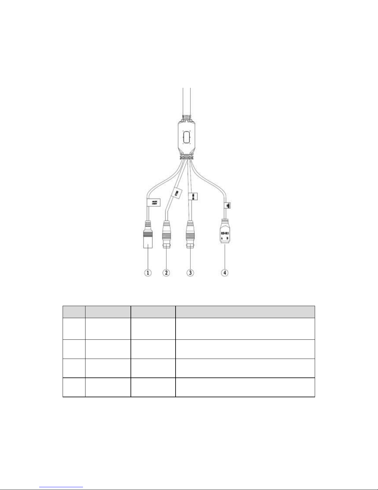
1.1 Multiple-function Combination Cable
You can refer to the following figure for multiple-function combination cable information. See
Figure 1-1.
Figure 1-1 Multiple-function combination cable
Please refer to the following sheet for detailed information.
SN
Port Name
Function
Note
1
DC 12V/ AC
24V
Power input
port
Power port. Input DC 12V/AC 24V (Please use
the provided conversion cable)
2
CVBS
Video output
port
Output analog video signal. It can connect to the
TV monitor to view the video.
3
HD-SDI
SDI output
Send out SDI video stream conforming to the
HD-SDI standard.
4
RS485
RS485 port
RS485 port. Control the 485 configuration tool to
set video parameter.
1.2 Framework and Dimension
Please refer to the following figure for dimension information. The unit is mm. See Figure 1-2 and
Figure 1-3.
Page 6

2
Figure 1-2 Dimension illustration 1
Figure 1-3 Dimension illustration 2
Page 7

3
2 Installation
2.1 Device Installation
Please follow the steps listed below to install the device. Please refer to Figure 2-1 for reference.
Please draw the installation holes in the installation surface and then mark three
expansion bolts holes in the surface. Insert three bolts in the hole and secure firmly.
Please line up the installation holes of the bottom of the pendant mount bracket to the
installation holes in the surface. Then insert the three bolts to the holes of the bottom of
the bracket. Finally fasten the device on the installation surface.
Figure 2-1 Device installation illustration 1
2.2 Lens Adjustment
Turn counter clockwise to remove the lens cover, now you can see the iris front and rear control
rod. The front control rod is to focus and the rear control rod is to zoom. See Figure 2-2. Please
turn clockwise to fix the lens cover back firmly.
Important
Please remove the sunshield first and remove the lens cover if you can not unfasten the lens
cover.
The lens cover has the waterproof function. Please make sure it is secure after you
complete the lens adjustment.
The motorized series is equipped with motorized lens which do not require manual
adjustment.
Page 8

4
Figure 2-2 Lens adjustment
2.3 Bracket Adjustment
You can use a M4 inner hex screw to control the bracket. Please use the inner hex wrench from
the installation accessories bag to unfasten the screw. See Figure 2-3.The horizontal angle of the
rear cover can rotate 360°, the tilt angle can rotate 90° and the chassis can rotate 360°.
Please use the inner hex wrench to secure the screw firmly after you complete the setup.
Important
Please make sure the M4 inner hex screw or M4 inner hex flat tight screws are firm,
otherwise it may result in chassis vibration and the camera cannot fix to a specified angle.
Page 9

5
Figure 2-3 Bracket adjustment
2.4 OSD Button
The OSD button is shown as in Figure 2-4 and Figure 2-5.
In Figure 2-5, press the button in the middle for a long time, you can go to the menu interface,
Press the middle button for a short time, you can confirm current operation. Use the up/down
button to select the menu item and then use the left/right button to set the parameter value.
Page 10

6
Figure 2-4 OSD button 1
Figure 2-5 OSD button 2
Page 11

7
3 HDC Configuration Tool
3.1 Overview
You can use HDC configuration tool to set the device parameter and upgrade the system.
3.2 Operation
Double click the “485Configs.exe” icon; you can see an interface is shown as in Figure 3-1.
In the device interface, you can view COM setup, parameter setup, OSD, upgrade information
and etc.
The parameter interface is shown as in Figure 3-1.
Figure 3-1 Parameter interface
The OSD interface is shown as in Figure 3-2.
Figure 3-2 OSD interface
Page 12

8
The upgrade interface is shown as in Figure 3-3.
Figure 3-3 Upgrading interface
You can refer to the following sheet for detailed information.
Item
Note
COM Setup
COM
Select the corresponding COM number.
Baud rate
Default value is 9600. (Read-only)
Parity
None
Data bit
Default value is 8. (Read-only).
Stop bit
Default value is 1. (Read-only).
Current status
Display the corresponding COM status.
Parameter
Setup
Color
Brightness
Set the brightness value to adjust the video bright and
dark level. The value ranges from 0 to 100.
Contrastness
It includes two options: Enable/disable. You can
check the box to enable the contrastness
function.
After you enabled this function, you can set the
different value to control the contrastness. The
value ranges from 0 to 100.
Please note the BLC function and the contrast
function can not be valid at the same time.
Hue
Set the hue value to adjust the video hue. The value
ranges from 0 to 100.
Saturation
Set the saturation value to adjust the video saturation.
The value ranges from 0 to 100.
BLC
The BLC has three options: manual/auto/disable. You
can check the box to select the corresponding mode.
In the manual mode, the value you set here is the
actual backlight value.
In the auto mode, the value ranges from 0 to 100
according to the actual environments.
In the disable mode, the BLC function is disabled.
The value ranges from 0 to 100.
Please note the BLC function and the contrast
function can not be valid at the same time.
Page 13

9
Exposure
Shutter
It is to set the shutter time. It includes the following
modes.
Auto: System auto adjusts the shutter time
according to the current environments,
Manual: 1/3, 1/6……1/50s, 1/120s,… ; shutter
time is 1/3, 1/6…1/50, 1/120….
Customized zone: After you selected current
mode, you can see there is a period setup
interface. System can auto adjust in the period
you specified.
Customized value: After you selected the mode,
you can see the time period setup interface. You
can input the shutter value in the current
interface.
Gain
It includes two modes: auto/manual. You can check
the box to select the corresponding mode.
In the manual mode, your input value is the actual
value.
In the auto mode, the value ranges from 0 to the
setup value according to the actual environments.
Aperture
It includes two options: auto/no-auto.
In the auto mode, system can automatically
adjust the best aperture value according to the
current environments.
In the non-auto mode, the aperture is all open.
Exposure
compensation
There are 15 levels ranging from -7 to 7. You can set
the corresponding value to adjust the video total
brightness.
Others
Mirror
It is the pan rotation. You can check the box to enable
this function. Otherwise it is in normal mode.
Negative
video
It is to turn the bright part to the dark part and turn the
dark part to the bright part. You can check the box to
enable this function. Otherwise it is in normal mode.
WB
It includes: disable, auto, daytime, night, customized.
In the customized mode, you need to put a white
paper before the lens and then click the Trigger
button.
Sharpness
It is to set the video sharpness level. There are total
16 levels.
WDR
The level ranges from 1 to 3.
Day/night
mode
It includes: day/night/auto.
In the auto mode, system automatically sets the
day or night mode according to the current
environments.
In the day mode, the video is color.
In the night mode, the video is black and white.
Scene setting
You can select the corresponding scene mode
according to the various environments.
Default
Restore system default setup.
Save
Save current setup
OSD
Go to the main menu. Use the up/down button to the
corresponding item and then use the left/right button
to adjust the parameter.
System upgrade
Select the upgrade file and update the system. It may
take 25 minutes if It s to update the hardware version.
The OSD setup interface is shown as in Figure 3-4.
Page 14

10
Figure 3-4 OSD setup
Page 15

11
Appendix Toxic or Hazardous Materials or Elements
Component Name
Toxic or Hazardous Materials or Elements
Pb
Hg
Cd
Cr VI
PBB
PBDE
Circuit Board Component
○ ○ ○ ○ ○
○
Case
○ ○ ○ ○ ○
○
Wire and Cable
○ ○ ○ ○ ○
○
Packing Components
○ ○ ○ ○ ○
○
Accessories
○ ○ ○ ○ ○
○
O: Indicates that the concentration of the hazardous substance in all homogeneous materials in
the parts is below the relevant threshold of the SJ/T11363-2006 standard.
X: Indicates that the concentration of the hazardous substance of at least one of all
homogeneous materials in the parts is above the relevant threshold of the SJ/T11363-2006
standard. During the environmental-friendly use period (EFUP) period, the toxic or hazardous
substance or elements contained in products will not leak or mutate so that the use of these
(substances or elements) will not result in any severe environmental pollution, any bodily injury or
damage to any assets. The consumer is not authorized to process such kind of substances or
elements, please return to the corresponding local authorities to process according to your local
government statutes.
Note:
This quick start guide is for reference only. Slight difference may be found in user
interface.
All the designs and software here are subject to change without prior written notice.
All trademarks and registered trademarks are the properties of their respective
owners.
If there is any uncertainty or controversy, please refer to the final explanation of us.
Please visit our website or contact your local service engineer for more information.
 Loading...