

Page 1

Dahua HDCVI Standalone DVR User’s Manual
Dahua HDCVI Standalone DVR User’s Manual
V1.3.1
Page 2

i
Table of Contents
1 FEATURES AND SPECIFICATIONS ....................................................... 8
1.1 Overview ................................................................................................................................... 8
1.2 Features .................................................................................................................................... 8
1.3 Specifications ........................................................................................................................... 9
1.3.1 HCVR82XXA-S3 Series ..................................................................................................... 9
1.3.2 HCVR84XXL-S3 Series ................................................................................................... 11
1.3.3 HCVR88XXS-S3 Series ................................................................................................... 14
1.3.4 HCVR88XXS-URH-S3 Series ......................................................................................... 16
1.3.5 XVR88XXS Series ............................................................................................................ 18
2 OVERVIEW AND CONTROLS ................................ ............................... 21
2.1 Front Panel ............................................................................................................................. 21
2.1.1 HCVR82XXA-S3/ HCVR84XXL-S3/HCVR88XXS-S3/ XVR88XXS Series.............. 21
2.1.2 HCVR88XXS-URH-S3 Series ......................................................................................... 22
2.2 Rear Panel .............................................................................................................................. 22
2.2.1 HCVR82XXA-S3 Series ................................................................................................... 22
2.2.2 HCVR84XXL-S3/HCVR88XXS-S3/ HCVR88XXS-URH-S3/XVR88XXS Series ..... 24
2.3 Connection Sample ............................................................................................................... 28
2.4 Remote Control ...................................................................................................................... 29
2.5 Mouse Control ........................................................................................................................ 31
2.6 Virtual Keyboard & Front Panel ........................................................................................... 32
2.6.1 Virtual Keyboard ............................................................................................................... 32
2.6.2 Front Panel ........................................................................................................................ 33
Page 3

ii
3 INSTALLATION AND CONNECTIONS .................................................. 34
3.1 Check Unpacked DVR .......................................................................................................... 34
3.2 About Front Panel and Rear Panel ..................................................................................... 34
3.3 HDD Installation ..................................................................................................................... 34
3.3.1 HDD Calculation ............................................................................................................... 34
3.3.2 HDD Installation ................................................................................................................ 35
3.3.3 Rack Installation ................................................................................................................ 39
3.4 Connecting Power Supply .................................................................................................... 39
3.5 Connecting Video Input and Output Devices .................................................................... 39
3.5.1 Connecting Video Input.................................................................................................... 39
3.5.2 Connecting Video Output ................................................................................................ 39
3.6 Connecting Audio Input & Output, Bidirectional Audio .................................................... 40
3.6.1 Audio Input ......................................................................................................................... 40
3.6.2 Audio Output ...................................................................................................................... 40
3.7 Alarm Input and Output Connection ................................................................................... 40
3.7.1 Alarm Input and Output Details ...................................................................................... 41
3.7.2 Alarm Input Port ................................................................................................................ 42
3.7.3 Alarm Output Port ............................................................................................................. 42
3.7.4 Alarm Output Relay Parameters..................................................................................... 42
3.8 Change DVR Button Battery ................................................................................................ 43
3.9 RS485 ..................................................................................................................................... 43
3.10 Other Interfaces ..................................................................................................................... 44
4 OVERVIEW OF NAVIGATION AND CONTROLS .................................. 45
Page 4

iii
4.1 Initial Settings ......................................................................................................................... 45
4.1.1 Boot up ............................................................................................................................... 45
4.1.2 Device Initialization ........................................................................................................... 45
4.1.3 Reset Password ................................................................................................................ 48
4.1.4 Quick Settings ................................................................................................................... 53
4.2 Preview ................................................................................................................................... 87
4.2.1 Preview Window ............................................................................................................... 87
4.2.2 Preview Control ................................................................................................................. 88
4.2.3 Right-Click Menu ............................................................................................................... 91
4.2.4 Window Switch .................................................................................................................. 92
4.2.5 Video Color ................................................................ ................................ ........................ 92
4.2.6 Image .................................................................................................................................. 95
4.2.7 Auto Focus ......................................................................................................................... 97
4.2.8 Preview and Display ......................................................................................................... 98
4.2.9 Tour ................................................................................................................................... 101
4.3 Search Human Face (Optional) ......................................................................................... 104
4.4 Fisheye ................................................................................................................................. 105
4.4.1 Fisheye De-Warp During Preview Interface ............................................................... 105
4.4.2 Fisheye De-Warp During Playback .............................................................................. 107
4.5 Smart Track ......................................................................................................................... 107
4.6 PTZ Control ......................................................................................................................... 108
4.6.1 PTZ Settings .................................................................................................................... 108
4.6.2 PTZ Operation ................................................................................................................. 109
4.6.3 Coaxial Control ................................................................................................................ 111
4.6.4 Set PTZ Functions .......................................................................................................... 112
4.6.5 Call PTZ Functions ......................................................................................................... 115
4.7 Navigation Bar ..................................................................................................................... 116
4.7.1 Main Menu ....................................................................................................................... 117
4.7.2 Output Screen ................................................................................................................. 117
4.7.3 Previous/Next Screen .................................................................................................... 117
4.7.4 Tour ................................................................................................................................... 117
4.7.5 Favorites .......................................................................................................................... 117
4.7.6 Channel ............................................................................................................................ 119
4.7.7 PTZ ................................................................................................................................... 120
4.7.8 Color ................................................................................................................................. 120
4.7.9 Search .............................................................................................................................. 120
Page 5

iv
4.7.10 Alarm Status ............................................................................................................... 120
4.7.11 Channel Info ............................................................................................................... 120
4.7.12 Registration ................................................................................................................. 120
4.7.13 Network ....................................................................................................................... 120
4.7.14 HDD Manager ................................................................ ................................ ............. 121
4.7.15 USB Manager ............................................................................................................. 121
4.8 Record and Snapshot ......................................................................................................... 121
4.8.1 Record and Snapshot Control ...................................................................................... 121
4.8.2 Snapshot .......................................................................................................................... 125
4.9 Search and Playback .......................................................................................................... 129
4.9.1 Instant Playback .............................................................................................................. 129
4.9.2 Search .............................................................................................................................. 129
4.9.3 Smart Search Playback ................................................................................................. 136
4.9.4 Mark Playback ................................................................................................................. 137
4.9.5 Playback Image............................................................................................................... 138
4.9.6 Splice Playback ............................................................................................................... 138
4.9.7 File List ............................................................................................................................. 139
4.9.8 Other Aux Functions ..................................................................................................... 141
4.10 Backup .................................................................................................................................. 141
4.10.1 File Backup ................................................................................................................ 141
4.10.2 USB Device Auto Pop-up ........................................................................................ 142
4.11 Network ................................................................................................................................. 143
4.11.1 TCP/IP ......................................................................................................................... 143
4.11.2 Connection .................................................................................................................. 144
4.11.3 WIFI .............................................................................................................................. 145
4.11.4 3G/4G .......................................................................................................................... 146
4.11.5 PPPoE ......................................................................................................................... 147
4.11.6 DDNS ........................................................................................................................... 148
4.11.7 Sync Time ................................................................................................................... 150
4.11.8 Email ............................................................................................................................ 151
4.11.9 UPnP ............................................................................................................................ 152
4.11.10 SNMP........................................................................................................................... 154
4.11.11 Multicast ...................................................................................................................... 155
4.11.12 Register ....................................................................................................................... 157
4.11.13 Alarm Center ............................................................................................................... 158
4.11.14 P2P .............................................................................................................................. 159
Page 6

v
4.12 Account Manager ................................................................................................................ 160
4.12.1 Add User ..................................................................................................................... 160
4.12.2 Modify user ................................................................................................................. 163
4.12.3 Change Password ...................................................................................................... 165
4.12.4 Add/Modify Group ...................................................................................................... 166
4.12.5 ONVIF User ................................................................................................................ 167
4.13 Voice Manager ..................................................................................................................... 169
4.13.1 File Manager ............................................................................................................... 169
4.13.2 Schedule ..................................................................................................................... 170
4.14 Alarm Events ........................................................................................................................ 171
4.14.1 Video Detect ............................................................................................................... 171
4.14.2 Smart Plan (Optional) ................................................................................................ 181
4.14.3 IVS (Optional) ............................................................................................................. 182
4.14.4 Face Detection (Optional) ......................................................................................... 193
4.14.5 People Counting (Optional) ...................................................................................... 194
4.14.6 Audio Detect ............................................................................................................... 195
4.14.7 Smart Track (Optional) .............................................................................................. 196
4.14.8 Alarm Settings ............................................................................................................ 200
4.14.9 Abnormality ................................................................................................................. 208
4.14.10 Alarm Output ............................................................................................................... 212
4.15 Storage .................................................................................................................................. 212
4.15.1 HDD Manager ................................................................ ................................ ............. 212
4.15.2 FTP............................................................................................................................... 213
4.15.3 HDD Group ................................................................................................................. 215
4.15.4 Quota ........................................................................................................................... 218
4.15.5 HDD Detect ................................................................................................................. 219
4.15.6 RAID............................................................................................................................. 222
4.15.7 iSCSI ............................................................................................................................ 227
4.16 Channel Manager ................................................................ ................................ ................ 228
4.16.1 Image ........................................................................................................................... 228
4.16.2 Channel Name............................................................................................................ 230
4.16.3 Channel Type ............................................................................................................. 231
4.17 System Settings ................................................................................................................... 233
4.17.1 RS232 .......................................................................................................................... 233
4.17.2 POS .............................................................................................................................. 234
Page 7

vi
4.17.3 Security ........................................................................................................................ 237
4.18 System Maintain .................................................................................................................. 239
4.18.1 Auto Maintain .............................................................................................................. 239
4.18.2 Import/Export .............................................................................................................. 240
4.18.3 Default ......................................................................................................................... 241
4.18.4 System Upgrade ........................................................................................................ 241
4.19 Remote Device Manager .................................................................................................... 242
4.19.1 Connection Status ...................................................................................................... 242
4.19.2 Firmware ..................................................................................................................... 243
4.19.3 Camera Upgrade ........................................................................................................ 244
4.20 Info ......................................................................................................................................... 244
4.20.1 System Info ................................................................................................................. 244
4.20.2 Event Info .................................................................................................................... 251
4.20.3 Network Info ................................................................................................................ 253
4.20.4 Log Info ........................................................................................................................ 255
4.21 Shutdown .............................................................................................................................. 257
5 WEB OPERATION ............................................................................... 259
5.1 Network Connection ............................................................................................................ 259
5.2 Device Initialization ........................................................................................................... 259
5.3 Login ...................................................................................................................................... 262
5.4 Reset Password ................................................................................................................. 263
5.5 Preview ................................................................................................................................. 265
5.5.1 LAN Mode ........................................................................................................................ 265
5.5.2 WAN Login ....................................................................................................................... 272
5.6 Search Human Face ........................................................................................................... 272
Page 8

vii
5.7 Setup ..................................................................................................................................... 273
5.7.1 Camera ............................................................................................................................. 273
5.7.2 Network ............................................................................................................................ 291
5.7.3 Event ................................................................................................................................. 313
5.7.4 Storage ............................................................................................................................. 347
5.7.5 Setting .............................................................................................................................. 360
5.7.6 Security ............................................................................................................................ 384
5.8 Playback ............................................................................................................................... 385
5.8.1 Search Record ................................................................................................................ 386
5.8.2 Mark Playback ................................................................................................................. 388
5.8.3 Splice Playback ............................................................................................................... 390
5.8.4 Fisheye Playback De-Warp ........................................................................................... 391
5.8.5 File List ............................................................................................................................. 391
5.8.6 Playback ........................................................................................................................... 392
5.8.7 Download ......................................................................................................................... 392
5.8.8 Load more ........................................................................................................................ 393
5.8.9 Lock or Unlock File ......................................................................................................... 396
5.9 Alarm ..................................................................................................................................... 396
5.10 Information ............................................................................................................................ 397
5.10.1 Version......................................................................................................................... 397
5.10.2 Log ............................................................................................................................... 398
5.10.3 Online User ................................................................................................................. 399
5.10.4 HDD ............................................................................................................................. 400
5.10.5 Network Sniffer ........................................................................................................... 401
5.10.6 Report .......................................................................................................................... 401
5.11 Log out .................................................................................................................................. 402
5.12 Un-install Web Control ........................................................................................................ 403
6 SMARTPSS .......................................................................................... 404
7 FAQ ...................................................................................................... 405
Page 9

viii
APPENDIX A HDD CAPACITY CALCULATION ....................................... 413
APPENDIX B COMPATIBLE BACKUP DEVICES ....................................... 415
Appendix B-1 Compatible USB list ............................................................................................... 415
Appendix B-2 Compatible SD Card list ....................................................................................... 416
Appendix B-3 Compatible Portable HDD list .............................................................................. 416
Appendix B-4 Compatible USB DVD List ................................................................................... 416
Appendix B-5 Compatible SATA DVD List .................................................................................. 416
Appendix B-6 Compatible SATA HDD List ................................................................................. 417
APPENDIX C COMPATIBLE CD/DVD BURNER LIST ............................. 421
APPENDIX D COMPATIBLE DISPLAYER LIST ....................................... 422
APPENDIX E COMPATIBLE SWITCHER ................................................. 423
APPENDIX F COMPATIBLE WIRELESS MOUSE LIST ........................... 424
APPENDIX G EARTHING ......................................................................... 425
APPENDIX H RAID INTRODUCTION ....................................................... 431
Appendix H-1 About RAID ................................................................................................................ 431
Page 10

ix
Appendix H-2 RAID Level................................................................................................................. 431
Appendix H-3 RAID Capacity Calculation ...................................................................................... 433
Appendix H-4 RAID Usage Suggestions ........................................................................................ 433
APPENDIX I RJ45-RS232 CONNECTION CABLE DEFINITION ................ 434
Page 11

1
Welcome
Thank you for purchasing our HDCVI DVR!
This user’s manual is designed to be a reference tool for the installation and operation of
your system.
Here you can find information about this series standalone DVR features and functions, as
well as a detailed menu tree.
Before installation and operation please read the following safeguards and warnings
carefully!
Page 12

2
Cybersecurity Recommendations
Cybersecurity Recommendations
Mandatory actions to be taken towards cybersecurity
1. Change Passwords and Use Strong Passwords:
The number one reason systems get “hacked” is due to having weak or default passwords.
It is recommended to change default passwords immediately and choose a strong
password whenever possible. A strong password should be made up of at least 8
characters and a combination of special characters, numbers, and upper and lower case
letters.
2. Update Firmware
As is standard procedure in the tech-industry, we recommend keeping NVR, DVR, and IP
camera firmware up-to-date to ensure the system is current with the latest security
patches and fixes.
“Nice to have” recommendations to improve your network security
1. Change Passwords Regularly
Regularly change the credentials to your devices to help ensure that only authorized users
are able to access the system.
2. Change Default HTTP and TCP Ports:
● Change default HTTP and TCP ports for systems. These are the two ports used to
communicate and to view video feeds remotely.
● These ports can be changed to any set of numbers between 1025-65535. Avoiding the
default ports reduces the risk of outsiders being able to guess which ports you are using.
3. Enable HTTPS/SSL:
Set up an SSL Certificate to enable HTTPS. This will encrypt all communication between
your devices and recorder.
4. Enable IP Filter:
Enabling your IP filter will prevent everyone, except those with specified IP addresses,
from accessing the system.
5. Change ONVIF Password:
On older IP Camera firmware, the ONVIF password does not change when you change
the system’s credentials. You will need to either update the camera’s firmware to the latest
revision or manually change the ONVIF password.
Page 13

3
6. Forward Only Ports You Need:
● Only forward the HTTP and TCP ports that you need to use. Do not forward a huge
range of numbers to the device. Do not DMZ the device's IP address.
● You do not need to forward any ports for individual cameras if they are all connected to a
recorder on site; just the NVR is needed.
7. Disable Auto-Login on SmartPSS:
Those using SmartPSS to view their system and on a computer that is used by multiple
people should disable auto-login. This adds a layer of security to prevent users without the
appropriate credentials from accessing the system.
8. Use a Different Username and Password for SmartPSS:
In the event that your social media, bank, email, etc. account is compromised, you would
not want someone collecting those passwords and trying them out on your video
surveillance system. Using a different username and password for your security system
will make it more difficult for someone to guess their way into your system.
9. Limit Features of Guest Accounts:
If your system is set up for multiple users, ensure that each user only has rights to
features and functions they need to use to perform their job.
10. UPnP:
● UPnP will automatically try to forward ports in your router or modem. Normally this
would be a good thing. However, if your system automatically forwards the ports and you
leave the credentials defaulted, you may end up with unwanted visitors.
● If you manually forwarded the HTTP and TCP ports in your router/modem, this feature
should be turned off regardless. Disabling UPnP is recommended when the function is not
used in real applications.
11. SNMP:
Disable SNMP if you are not using it. If you are using SNMP, you should do so only
temporarily, for tracing and testing purposes only.
12. Multicast:
Multicast is used to share video streams between two recorders. Currently there are no
known issues involving Multicast, but if you are not using this feature, deactivation can
enhance your network security.
13. Check the Log:
If you suspect that someone has gained unauthorized access to your system, you can
check the system log. The system log will show you which IP addresses were used to
Page 14

4
login to your system and what was accessed.
14. Physically Lock Down the Device:
Ideally, you want to prevent any unauthorized physical access to your system. The best
way to achieve this is to install the recorder in a lockbox, locking server rack, or in a room
that is behind a lock and key.
15. Connect IP Cameras to the PoE Ports on the Back of an NVR:
Cameras connected to the PoE ports on the back of an NVR are isolated from the outside
world and cannot be accessed directly.
16. Isolate NVR and IP Camera Network
The network your NVR and IP camera resides on should not be the same network as your
public computer network. This will prevent any visitors or unwanted guests from getting
access to the same network the security system needs in order to function properly.
Page 15

5
Important Safeguards and Warnings
Icon
Note
DANGER
Indicates a high potential hazard which, if not avoided, will result in
death or serious injury.
1.Electrical safety
All installation and operation here should conform to your local electrical safety codes.
The product must be grounded to reduce the risk of electric shock.
We assume no liability or responsibility for all the fires or electrical shock caused by
improper handling or installation.
2.Transportation security
Heavy stress, violent vibration or water splash are not allowed during transportation,
storage and installation.
3.Installation
Keep upwards. Handle with care.
Do not apply power to the DVR before completing installation.
Do not place objects on the DVR.
4.Qualified engineers needed
All the examination and repair work should be done by the qualified service engineers.
We are not liable for any problems caused by unauthorized modifications or attempted
repair.
5.Environment
The DVR should be installed in a cool, dry place away from direct sunlight, inflammable,
explosive substances and etc.
6. Accessories
Be sure to use all the accessories recommended by manufacturer.
Before installation, please open the package and check all the components are included.
Contact your local retailer ASAP if something is broken in your package.
7. Lithium battery
Improper battery use may result in fire, explosion, or personal injury!
When replace the battery, please make sure you are using the same model!
RISK OF EXPLOSION IF BATTERY IS REPLACED BY AN INCORRECT TYPE.
DISPOSE OF USED BATTERIES ACCORDING TO THE INSTRUCTIONS.
Safety Instruction
Page 16
6
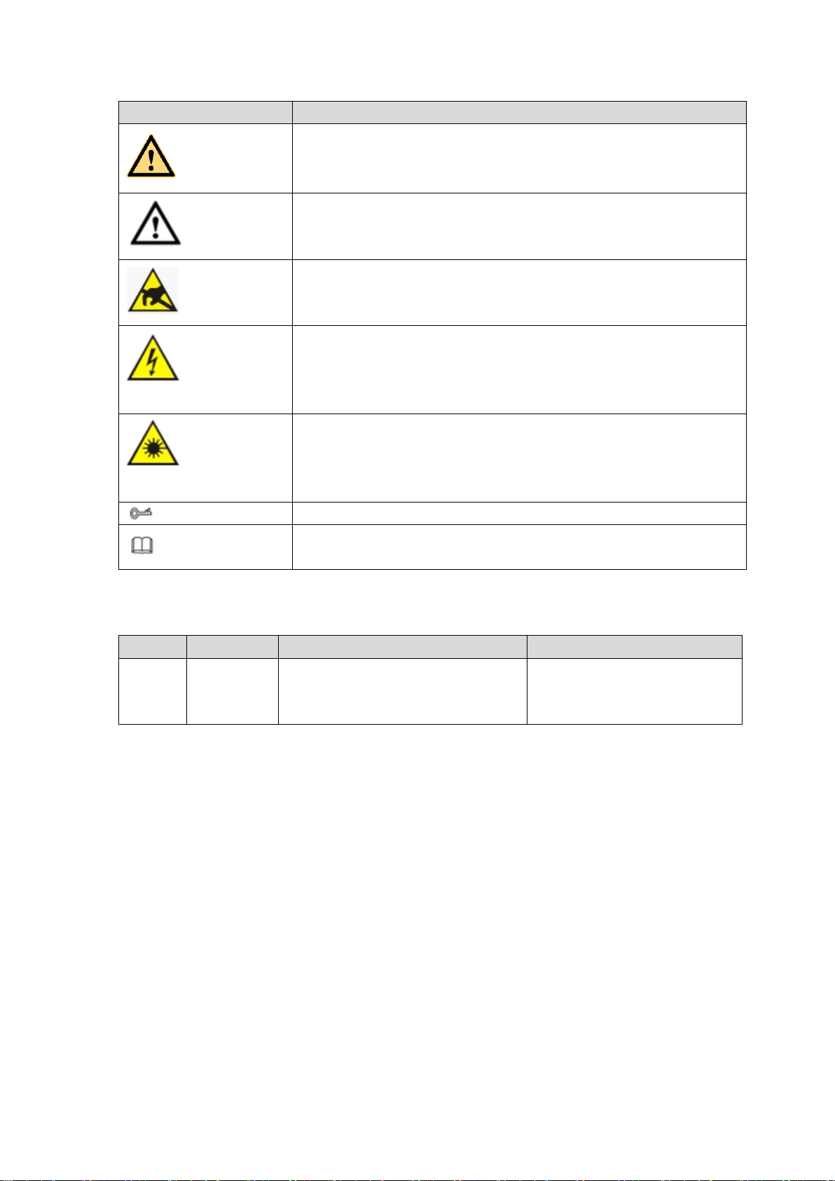
Icon
Note
WARNING
Indicates a medium or low potential hazard which, if not avoided,
could result in slight or moderate injury.
CAUTION
Indicates a potential risk which, if not avoided, could result in
property damage, data loss, lower performance, or unpredictable
result.
Anti-static
Indicates it is the static sensitive device.
Eletric shock
risk
Indicates presence of dangerous high voltage. There is a risk of
electric shock to persons.
High power
laser radiation risk
Indicates presence of high power laser radiation.
Tips
It is intended to help you to fix a problem or save your time.
Note
Provides additional information to emphasize or supplement
important points of the main text.
Revision History
No.
Version
Revision Content
Release Time
1
V1.3.1
Add two chapters: Privacy
protection notice and about the
manual.
2018.05
Privacy Protection Notice
As the device user or data controller, you might collect personal data of others'
such as face, fingerprints, car plate number, Email address, phone number, GPS
and so on. You need to be in compliance with the local privacy protection laws
and regulations to protect the legitimate rights and interests of other people by
implementing measures include but not limited to: providing clear and visible
identification to inform data subject the existence of surveillance area and
providing related contact.
About the Manual
The Manual is for reference only. If there is inconsistency between the
Manual and the actual product, the actual product shall prevail.
We are not liable for any loss caused by the operations that do not comply
Page 17

7
with the Manual.
The Manual would be updated according to the latest laws and regulations
of related regions. For detailed information, see the paper User's Manual,
CD-ROM, QR code or our official website. If there is inconsistency between
paper User's Manual and the electronic version, the electronic version shall
prevail.
All the designs and software are subject to change without prior written
notice. The product updates might cause some differences between the
actual product and the Manual. Please contact the customer service for the
latest program and supplementary documentation.
There still might be deviation in technical data, functions and operations
description, or errors in print. If there is any doubt or dispute, please refer to
our final explanation.
Upgrade the reader software or try other mainstream reader software if the
Guide (in PDF format) cannot be opened.
All trademarks, registered trademarks and the company names in the
Manual are the properties of their respective owners.
Please visit our website, contact the supplier or customer service if there is
any problem occurred when using the device.
If there is any uncertainty or controversy, please refer to our final
explanation.
Page 18

8
1 FEATURES AND SPECIFICATIONS
1.1 Overview
This standalone series DVR is an excellent digital monitor product designed for security
field.
It adopts embedded Linux OS to maintain reliable operation. Popular H.264 compression
algorithm and G.711 audio compression technology realize high quality, low bit stream.
Unique frame by frame play function is suitable for detailed analysis. It has various
functions such as record, playback, monitor at the same time and can guarantee audio
video synchronization. This series product has advanced technology and strong network
data transmission function.
This series device adopts embedded design to achieve high security and reliability. It can
work in the local end, and at the same time, when connecting it to the professional
surveillance software (PSS), it can connect to the security network to realize strong
network and remote monitor function.
This series product can be widely used in various areas such as banking,
telecommunication, electric power, interrogation, transportation, intelligent resident zone,
factory, warehouse, resources, and water conservancy.
1.2 Features
This series product has the following features:
Real-time surveillance
Support VGA port and HDMI port. Realize the surveillance through displayer. Support
HDMI, VGA, and TV output at the same time.
Storage function
Special data format to guarantee data security and can remove the risk of the vicious data
modification. Support digital watermark.
Compression format
Support multiple-channel audio and video. An independent hardware decodes the audio
and video signal from each channel to maintain video and audio synchronization.
Backup function
Support backup operation via USB port (such as U disk, portable HDD, burner)
Client-end user can download the file to local HDD to backup via network.
Record & playback function
Page 19

9
Support each channel real-time record independently, and at the same time it can support
Name
Parameters
HCVR8204A-S3
HCVR8208A-S3
HCVR8216A-S3
System
Main Processor
Industrial embedded micro controller
OS
Embedded LINUX
Video
Parameters
Video Encode
Standard
H.264H, H.264, H.264B
Encode
Resolution
1080P/720P/960H/D1/HD1/2CIF/CIF
search, forward play, network monitor, record search, download and etc.
Support various playback modes: slow play, fast play, backward play and frame by frame
play.
Support time title overlay so that you can view event accurate occurred time
Support customized zoom function during the preview.
Network operation
Support network remote real-time monitor, remote record search and remote PTZ control.
Alarm activation function
Several relay alarm outputs to realize alarm activation and on-site light control.
The alarm input port and output has the protection circuit to guarantee device safety.
Communication port
RS485 port can realize alarm input and PTZ control.
RS232 port can connect to keyboard, COM port of PC or the matrix control.
Standard Ethernet port can realize network access function.
The dual-network port has the multiple-access, fault-tolerance, load-balance setup mode.
PTZ control
Support PTZ decoder via RS485.
Intelligent operation
Mouse operation function
In the menu, support copy and paste setup function
UPNP (Universal Plug and Play)
Establish mapping connection between LAN and WAN via UPNP protocol.
Camera Self-adaptive
Auto recognize and work with the general analog camera and HD camera.
Slight function differences may be found due to different series.
1.3 Specifications
1.3.1 HCVR82XXA-S3 Series
Page 20

10
Name
Parameters
HCVR8204A-S3
HCVR8208A-S3
HCVR8216A-S3
Video Frame
Rate
PAL:1/16~25f/s;NTSC:1/16~30f/s
Video Frame
Rate
32Kbps-8192Kbps,
For 720P: default setup is 2Mbps,max supports 4Mbps.
For 1080P: default setup is 4Mbps,max supports 8Mbps.
Bit Stream Type
Video stream/composite stream
Dual-Stream
Support
Audio
Parameters
Encode
Standard
G.711A/G.711U/PCM
Audio Sampling
Rate
8KHz,16Bit
Audio Bit Rate
64Kbps
Video Port
Analog Video
Input
4-ch BNC port
(HDCVI/AHD/CVBS)
8-ch BNC
port(HDCVI/AHD/CV
BS)
16-ch BNC
port(HDCVI/AH
D/CVBS)
Network Video
Input
There is no IP
channel by
default.
Just click one
button to add 60
IP channels.
Support A/D
switch function,
max supports 64
IP channels.
Resolution: Max
1200W.
Decode
standard: H.265.
Connection total
network width:
256Mbps
There is no IP
channel by
default.
Just click one
button to add 56
IP channels.
Support A/D
switch function,
max supports 64
IP channels.
Resolution: Max
1200W.
Decode
standard: H.265.
Connection total
network width:
256Mbps
There is no
IP channel
by default.
Just click
one button
to add 48 IP
channels.
Support A/D
switch
function,
max
supports 64
IP channels.
Resolution:
Max
1200W.
Decode
standard:
H.265.
Connection
total
network
width:
256Mbps
Video Output
1-channel VGA output,
2-channel HDMI output,
VGA and HDMI1 output of the same video source;
Page 21

11
Name
Parameters
HCVR8204A-S3
HCVR8208A-S3
HCVR8216A-S3
VGA and HDMI2 output of different video sources;
HDMI1 supports 4K output, HDMI2 supports 1080P output.
Loop Output
N/A
Matrix Output
N/A
Audio Port
External Audio
Input
4-chanel RCA port
Coaxial Audio
Input
4-channel
8-channel
16-channel
Audio Output
1-channel RCA port. Output port reuses the bidirectional talk
output port.
Bidirectional
Talk Input
One independent audio talk input port.
Output port (RCA) reuses the audio output port.
Record
Record Mode
Schedule record/manual record/MD record/alarm record
Playback Mode
Instant playback, normal playback, event playback, mark
playback, smart playback
Record
Playback
Max 1/4/8/16-channel playback
Customized channel setup playback
Max 16-channel 1080P realtime playback or 1200W non realtime
playback
Backup Mode
HDD, burner, USB device, network backup
Alarm
Alarm Input
16-channel alarm input
Alarm Output
3-channel output
HDD
HDD Port
2 SATA ports, one eSATA port
One HDD Space
8T
Communication
Port
Network
2 RJ45 port, 1000Mbps Ethernet port
Communication
1 RS485 port, 1 RS232 port
USB
3 USB ports(One USB2.0 port at the front panel and two USB3.0
ports at the rear panel)
Others
Power
DC12V
Power
Consumption
≤25W
≤27W
≤32W
Working
Temperature
-10℃-+55℃
Working
Humidity
10%~90%
Dimensions
1U case,323mm(W)×375mm(D)×53mm(H)
Weight
≤2.30KG
≤2.35KG
≤2.45KG
Installation
Mode
Desk
1.3.2 HCVR84XXL-S3 Series
Page 22

12
Name
Parameters
HCVR8404L-S3
HCVR8408L-S3
HCVR8416L-S3
System
Main Processor
Industrial embedded micro controller
OS
Embedded LINUX
Video
Parameters
Video Encode
Standard
H.264H, H.264, H.264B
Encode
Resolution
1080P/720P/960H/D1/HD1/2CIF/CIF
Video Frame
Rate
PAL:1/16~25f/s;NTSC:1/16~30f/s
Video Frame
Rate
32Kbps-8192Kbps,
For 720P: default setup is 2Mbps,max supports 4Mbps.
For 1080P: default setup is 4Mbps,max supports 8Mbps.
Bit Stream Type
Video stream/composite stream
Dual-Stream
Support
Audio
Parameters
Encode
Standard
G.711A/G.711U/PCM
Audio Sampling
Rate
8KHz,16Bit
Audio Bit Rate
64Kbps
Video Port
Analog Video
Input
4-ch BNC port
(HDCVI/AHD/CVBS)
8-ch BNC
port(HDCVI/AHD/CV
BS)
16-ch BNC
port(HDCVI/AH
D/CVBS)
Network Video
Input
There is no IP
channel by
default.
Just click one
button to add 60
IP channels.
Support A/D
switch function,
max supports 64
IP channels.
Resolution: Max
1200W.
Decode
standard: H.265.
Connection total
network width:
256Mbps
There is no IP
channel by
default.
Just click one
button to add 56
IP channels.
Support A/D
switch function,
max supports 64
IP channels.
Resolution: Max
1200W.
Decode
standard: H.265.
Connection total
network width:
256Mbps
There is no
IP channel
by default.
Just click
one button
to add 48 IP
channels.
Support A/D
switch
function,
max
supports 64
IP channels.
Resolution:
Max
1200W.
Decode
standard:
H.265.
Connection
total
Page 23

13
Name
Parameters
HCVR8404L-S3
HCVR8408L-S3
HCVR8416L-S3
network
width:
256Mbps
Video Output
1-channel VGA output,
2-channel HDMI output,
1-channel VIDEO OUT,
VGA and HDMI1 output of the same video source;
VGA and HDMI2 output of different video sources;
VIDEO OUT supports multiple-window analog channel output.
HDMI1 supports 4K output, HDMI2 supports 1080P output.
Loop Output
N/A
Matrix Output
VIDEO OUT supports multiple-window analog channel output.
Audio Port
External Audio
Input
4-chanel BNC port
Coaxial Audio
Input
4-channel
8-channel
16-channel
Audio Output
1-channel BNC port.
Bidirectional
Talk Input
One independent audio talk input port and one independent
output port (BNC)
Record
Record Mode
Schedule record/manual record/MD record/alarm record
Playback Mode
Instant playback, normal playback, event playback, mark
playback, smart playback
Record
Playback
Max 1/4/8/16-channel playback
Customized channel setup playback
Max 16-channel 1080P realtime playback or 1200W non realtime
playback
Backup Mode
HDD, burner, USB device, network backup
Alarm
Alarm Input
16-channel alarm input
Alarm Output
6-channel output
HDD
HDD Port
4 SATA port, one eSATA port
One HDD Space
8T
Communication
Port
Network
1 RJ45 port, 1000Mbps Ethernet port
Communication
1 RS485 port, 1 RS232 port, 1 RS422 port
USB
3 USB ports(One USB2.0 port at the front panel and two USB3.0
ports at the rear panel)
Others
Power
AC90V~264V
Power
Consumption
≤33W
≤35W
≤40W
Working
Temperature
-10℃-+55℃
Working
Humidity
10%~90%
Page 24

14
Name
Parameters
HCVR8404L-S3
HCVR8408L-S3
HCVR8416L-S3
Dimensions
1.5U case,440mm(W)×410mm(D)×70mm(H)
Weight
≤6.95KG
≤6.90KG
≤7.00KG
Installation
Mode
Desk
Name
Parameters
HCVR8804S-S3
HCVR8808S-S3
HCVR8816S-S3
System
Main Processor
Industrial embedded micro controller
OS
Embedded LINUX
Video
Parameters
Video Encode
Standard
H.264H, H.264, H.264B
Encode
Resolution
1080P/720P/960H/D1/HD1/2CIF/CIF
Video Frame
Rate
PAL:1/16~25f/s;NTSC:1/16~30f/s
Video Frame
Rate
32Kbps-8192Kbps,
For 720P: default setup is 2Mbps,max supports 4Mbps.
For 1080P: default setup is 4Mbps,max supports 8Mbps.
Bit Stream Type
Video stream/composite stream
Dual-Stream
Support
Audio
Parameters
Encode
Standard
G.711A/G.711U/PCM
Audio Sampling
Rate
8KHz,16Bit
Audio Bit Rate
64Kbps
Video Port
Analog Video
Input
4-ch BNC port
(HDCVI/AHD/CVBS)
8-ch BNC
port(HDCVI/AHD/CV
BS)
16-ch BNC
port(HDCVI/AH
D/CVBS)
Network Video
Input
There is no IP
channel by
default.
Just click one
button to add 60
IP channels.
Support A/D
switch function,
max supports 64
IP channels.
Resolution: Max
1200W.
Decode
standard: H.265.
There is no IP
channel by
default.
Just click one
button to add 56
IP channels.
Support A/D
switch function,
max supports 64
IP channels.
Resolution: Max
1200W.
Decode
standard: H.265.
There is no
IP channel
by default.
Just click
one button
to add 48 IP
channels.
Support A/D
switch
function,
max
supports 64
IP channels.
Resolution:
1.3.3 HCVR88XXS-S3 Series
Page 25

15
Name
Parameters
HCVR8804S-S3
HCVR8808S-S3
HCVR8816S-S3
Connection total
network width:
256Mbps
Connection total
network width:
256Mbps
Max
1200W.
Decode
standard:
H.265.
Connection
total
network
width:
256Mbps
Video Output
1-channel VGA output,
2-channel HDMI output,
1-channel VIDEO OUT,
VGA and HDMI1 output of the same video source;
VGA and HDMI2 output of different video sources;
VIDEO OUT supports multiple-window analog channel output.
HDMI1 supports 4K output, HDMI2 supports 1080P output.
Loop Output
N/A
Matrix Output
VIDEO OUT supports multiple-window analog channel output.
Audio Port
External Audio
Input
4-chanel BNC port
8-chanel BNC port
16-chanel BNC
port
Coaxial Audio
Input
4-channel
8-channel
16-channel
Audio Output
1-channel BNC port.
Bidirectional
Talk Input
One independent audio talk input port and one independent output
port (BNC)
Record
Record Mode
Schedule record/manual record/MD record/alarm record
Playback Mode
Instant playback, normal playback, event playback, mark
playback, smart playback
Record
Playback
Max 1/4/8/16-channel playback
Customized channel setup playback
Max 16-channel 1080P realtime playback or 1200W non realtime
playback
Backup Mode
HDD, burner, USB device, network backup
Alarm
Alarm Input
16-channel alarm input
Alarm Output
6-channel output
HDD
HDD Port
8 SATA ports, one eSATA port
One HDD Space
8T
Communication
Port
Network
2 RJ45 ports, 1000Mbps Ethernet port
Communication
1 RS485 port, 1 RS232 port, 1 RS422 port
USB
4 USB ports(Two USB2.0 ports at the front panel and two USB3.0
ports at the rear panel)
Page 26

16
Name
Parameters
HCVR8804S-S3
HCVR8808S-S3
HCVR8816S-S3
Others
Power
AC90V~264V
Power
Consumption
≤33W
≤35W
≤40W
Working
Temperature
-10℃-+55℃
Working
Humidity
10%~90%
Dimensions
2U case,440mm(W)×460mm(D)×89mm(H)
Weight
≤7.25KG
≤7.30KG
≤7.40KG
Installation
Mode
Desk
1.3.4 HCVR88XXS-URH-S3 Series
Name
Parameters
HCVR8808S-URH-S3
HCVR8816S-URH-S3
System
Main Processor
Industrial embedded micro controller
OS
Embedded LINUX
Video
Parameters
Video Encode
Standard
H.264H, H.264, H.264B
Encode
Resolution
1080P/720P/960H/D1/HD1/2CIF/CIF
Video Frame
Rate
PAL:1/16~25f/s;NTSC:1/16~30f/s
Video Frame
Rate
32Kbps-8192Kbps,
For 720P: default setup is 2Mbps,max supports 4Mbps.
For 1080P: default setup is 4Mbps,max supports 8Mbps.
Bit Stream Type
Video stream/composite stream
Dual-Stream
Support
Audio
Parameters
Encode
Standard
G.711A/G.711U/PCM
Audio Sampling
Rate
8KHz,16Bit
Audio Bit Rate
64Kbps
Video Port
Analog Video
Input
8-ch BNC
port(HDCVI/AHD/CVBS)
16-ch BNC
port(HDCVI/AHD/CVBS)
Network Video
Input
There is no IP channel by
default.
Just click one button to add
56 IP channels.
Support A/D switch
function. After you disabled
one analog channel, you
can add one IP channel.
System max supports 64
There is no IP channel by
default.
Just click one button to add
48 IP channels.
Support A/D switch
function. After you disabled
one analog channel, you
can add one IP channel.
System max supports 64
Page 27

17
Name
Parameters
HCVR8808S-URH-S3
HCVR8816S-URH-S3
IP channels.
The connection bandwidth
is 160Mbps when there are
some IP channels. The
connection bandwidth is
200Mbps when there all IP
channels.
IP channels.
The connection bandwidth
is 160Mbps when there are
some IP channels. The
connection bandwidth is
200Mbps when there all IP
channels.
Video Output
1-ch PAL/NTSC, BNC (1.0VP- P, 75Ω) composite video signal
output.
1-ch VGA output.
2-ch HDMI output. HDMI port1 has the same video source as the
VGA. HDMI port2 can have different video source from the VGA,
support GUI operation.
Support TV/VGA/HDMI1/HDMI2 video output at the same time.
Loop Output
N/A
Matrix Output
VIDEO OUT supports multiple-window analog channel output.
Audio Port
External Audio
Input
8-chanel BNC port
16-chanel BNC port
Coaxial Audio
Input
8-channel
16-channel
Audio Output
1-channel BNC port.
Bidirectional
Talk Input
One independent audio talk input port and one independent output
port (BNC)
Record
Record Mode
Schedule record/manual record/MD record/alarm record
Playback Mode
Instant playback, normal playback, event playback, mark
playback, smart playback
Record
Playback
Max 1/4/8/16-channel playback
Customized channel setup playback
Max 16-channel 1080P realtime playback or 12MP non realtime
playback
Backup Mode
HDD, burner, USB device, network backup
Alarm
Alarm Input
16-channel alarm input
Alarm Output
6-channel output
HDD
HDD Port
8 SATA ports, one eSATA port
One HDD Space
8T
Communication
Port
Network
2 RJ45 ports, 1000Mbps Ethernet port
Communication
1 RS485 port, 1 RS232 port, 1 RS422 port
USB
4 USB ports(Two USB2.0 ports at the front panel and two USB3.0
ports at the rear panel)
Others
Power
AC90~264V 50+2% Hz
Power
Consumption
≤40W (No adapter, no HDD)
Page 28

18
Name
Parameters
HCVR8808S-URH-S3
HCVR8816S-URH-S3
Working
Temperature
-10℃-+55℃
Working
Humidity
10%~90%
Dimensions
2U case,444(W) x430 (D) x87mm(H)
Weight
11.5-13.0KG(No HDD)
Installation
Mode
Desktop/rack installation
Name
Parameters
XVR8808S
XVR8816S
System
Main Processor
Industrial embedded micro controller
OS
Embedded LINUX
Video
Parameters
Video Encode
Standard
H.264
Encode
Resolution
4K/4MP/1080P/720P/960H/D1/HD1/2CIF/CIF
Video Frame
Rate
PAL:1/16~25f/s;NTSC:1/16~30f/s
Video Frame
Rate
32Kbps-12288Kbps,
For 720P: default setup is 2Mbps,max supports 4Mbps.
For 1080P: default setup is 4Mbps,max supports 8Mbps.
Bit Stream Type
Video stream/composite stream
Dual-Stream
Support
Audio
Parameters
Encode
Standard
G.711A/G.711U/PCM
Audio Sampling
Rate
8KHz,16Bit
Audio Bit Rate
64Kbps
Video Port
Analog Video
Input
8-ch BNC port
(HDCVI/AHD/HDTVI/CVBS)
16-ch BNC port
(HDCVI/AHD/HDTVI/CVBS)
Network Video
Input
There is no IP channel by
default.
Just click one button to add
56 IP channels.
Support A/D switch
function. After you disabled
one analog channel, you
can add one IP channel.
System max supports 64
IP channels. Connection
total network width:
There is no IP channel by
default.
Just click one button to add
48 IP channels.
Support A/D switch
function. After you disabled
one analog channel, you
can add one IP channel.
System max supports 64
IP channels. Connection
total network width:
1.3.5 XVR88XXS Series
Page 29

19
Name
Parameters
XVR8808S
XVR8816S
256Mbps.
256Mbps.
Video Output
1-ch PAL/NTSC, BNC (1.0VP- P, 75Ω) composite video signal
output.
1-ch VGA output.
2-ch HDMI output. HDMI port1 has the same video source as the
VGA. HDMI port2 can have different video source from the VGA,
support GUI operation.
Support TV/VGA/HDMI1/HDMI2 video output at the same time.
Loop Output
Support
Matrix Output
VIDEO OUT supports multiple-window analog channel output.
Audio Port
External Audio
Input
8-chanel BNC port
16-chanel BNC port
Coaxial Audio
Input
N/A
N/A
Audio Output
1-channel 200-3000mv 5KΩ, BNC port.
Bidirectional
Talk Input
One independent audio talk input port and one independent output
port (200-3000mv 5KΩ,BNC)
Record
Record Mode
Schedule record/manual record/MD record/alarm record
Playback Mode
Instant playback, normal playback, event playback, mark
playback, smart playback
Record
Playback
Max 1/4/8/16-channel playback
Customized channel setup playback
Max 16-channel 1080P realtime playback or 12MP non realtime
playback
Backup Mode
HDD, burner, USB device, network backup
Alarm
Alarm Input
16-channel alarm input
Alarm Output
6-channel output (Include one controllable DC+12V output)
HDD
HDD Port
8 SATA ports, one eSATA port
One HDD Space
8T
Communication
Port
Network
2 RJ45 ports, 1000Mbps Ethernet port
Communication
1 RS485 port, 1 RS232 port, 1 RS422 port
USB
4 USB ports(Two USB2.0 ports at the front panel and two USB3.0
ports at the rear panel)
Others
Power
AC90~264V 50+2% Hz
Power
Consumption
≤40W (With adapter, no HDD)
Working
Temperature
-10℃-+55℃
Working
Humidity
10%~90%
Dimensions
2U case,444(W) x460 (D) x89mm(H)
Weight
7.0-8.0KG(No HDD)
Page 30

20
Name
Parameters
XVR8808S
XVR8816S
Installation
Mode
Desktop/rack installation
Page 31

21
2 Overview and Controls
Icon
Name
Function
STATUS
Status indicator light
The blue light becomes on when the device is
malfunction.
HDD
HDD status indicator
light
The blue light becomes on when the HDD is
malfunction.
NET
Network status indicator
light
The blue light becomes on when the network
connection is abnormal.
POWER
Power status indicator light
The blue light is on when the power connection is
OK.
This section provides information about front panel and rear panel. When you install this
series DVR for the first time, please refer to this part first.
2.1 Front Panel
2.1.1 HCVR82XXA-S3/ HCVR84XXL-S3/HCVR88XXS-S3/ XVR88XXS Series
For HCVR82XXA-S3, the front panel is shown as below. See Figure 2-1.
Figure 2-1
For HCVR84XXL-S3, the front panel is shown as below. See Figure 2-2.
Figure 2-2
For HCVR88XXS-S3/XVR88XXS, the front panel is shown as below. See Figure 2-3.
Figure 2-3
Please refer to the following sheet for front panel button information.
Page 32

22
Icon
Name
Function
USB port
Connect to peripheral USB storage device, mouse
and etc.
2.1.2 HCVR88XXS-URH-S3 Series
SN
Name
Icon
Function
1
Alarm
indicator
light
ALARM
Alarm indicator light
The light becomes on when there is an alarm such as
local alarm, IPC alarm and other abnormal event.
The light becomes off when there is no alarm.
2
HDD
indicator
light
HDD
HDD indicator light
The light becomes on when there is no HDD, HDD error
or HDD space is insufficient.
The light is off when the HDD is working properly.
3
Network
indicator
light
NET
Network indicator light
The light becomes on when the network is abnormal.
The light becomes off when the network is working
properly.
4
Power
indicator
light
POWER
Power indicator light
The light becomes on when the power supplying
connection is OK.
The light becomes off when there is no power
connection.
5
Power
on-off
button
Press it to boot up or shut down the device.
6
USB port
Connect to peripheral USB device, portable HDD and etc.
The front panel is shown as in Figure 2-4.
Figure 2-4
Please refer to the following sheet for detailed information.
2.2 Rear Panel
2.2.1 HCVR82XXA-S3 Series
The rear panel is shown as below. See Figure 2-5.
Page 33

23
Here we use HCVR8216A-S3 as an example.
SN
Icon
Name
Note
1
VIDEO IN
Video input port
Connect to analog camera to input video
signal.
2
MIC IN
Audio input port
Bidirectional talk input port. It is to receive
the analog audio signal output from the
devices such as microphone, pickup.
3
AUDIO OUT
Audio output port
Audio output port. It is to output the
analog audio signal to the devices such
as the sound box.
4
AUDIO IN
Audio input port
It is to receive the analog audio signal
output from the devices such as
microphone.
5
RS-232
RS-232 debug COM.
It is for general COM debug to configure
IP address or transfer transparent COM
data.
6
1~16
Alarm input port 1~16
There are four groups. The first group
is from port 1 to port 4, the second
group is from port 5 to port 8, the third
group is from 9 to 12, and the fourth
group is from 13 to 16. They are to
receive the signal from the external
alarm source. There are two types;
NO (normal open)/NC (normal close).
When your alarm input device is
using external power, please make
sure the device and the DVR have
the same ground.
GND
Ground
7 GND
Ground
8 Power switch
Power on/off button.
Figure 2-5
Please refer to the following sheet for detailed information.
Page 34

24
SN
Icon
Name
Note
9
NO1~NO3
Alarm output port 1~5
3 groups of alarm output ports.
(Group 1 : port NO1 ~ C1,Group
2:port NO2~C2,Group 3:port NO3~
C3)).Output alarm signal to the alarm
device. Please make sure there is
power to the external alarm device.
NO:Normal open alarm output port.
C:Alarm output public end.
C1~C3
A
RS-485 communication
port
RS485_A port. It is the cable A. You can
connect to the control devices such as
speed dome PTZ.
B
RS485_B.It is the cable B. You can
connect to the control devices such as
speed dome PTZ.
GND
Ground
10 Power input port
Input DC 12V.
11 USB port
USB port. Connect to mouse, USB
storage device, USB burner and etc.
12
HDMI1
High Definition Media
Interface 1
High definition audio and video signal
output port. It outputs the same video
source as VGA. It supports 4K resolution
output and supports mouse operation and
control.
Please note when the HDMI output
resolution is 4K, the VGA output stops.
13
HDMI2
High Definition Media
Interface 2
High definition audio and video signal
output port. It max supports 1080P
resolution. Its video source can be
different from the HDMI1/VGA. It supports
digital channel output.
14 Network port
1000M Ethernet port
15
VGA
VGA video output
VGA video output port. Output analog
video signal. It can connect to the monitor
to view analog video.
2.2.2 HCVR84XXL-S3/HCVR88XXS-S3/ HCVR88XXS-URH-S3/XVR88XXS Series
The HCVR84XXL-S3 rear panel is shown as below. See Figure 2-6.
Here we use HCVR8416L-S3 as an example.
Page 35

25
Figure 2-6
The HCVR88XXS-S3 rear panel is shown as below. See Figure 2-7.
Here we use HCVR8816S-S3 as an example.
Figure 2-7
The HCVR88XXS-URH-S3 rear panel is shown as below. See Figure 2-8.
Here we use HCVR8816S-URH-S3 as an example.
Figure 2-8
The XVR88XXS rear panel is shown as below. See Figure 2-9.
Here we use XVR8816S as an example.
Page 36

26
Figure 2-9
SN
Icon
Name
Note
1
AUDIO IN
Audio input port
It is to receive the analog audio signal
output from the devices such as
microphone.
2
MIC IN
Audio input port
Bidirectional talk input port. It is to receive
the analog audio signal output from the
devices such as microphone, pickup.
3
MIC OUT
Bidirectional talk output
port
Output bidirectional talk analog signal to
sound box and etc.
Bidirectional talk output.
Audio output of single-window
monitor mode.
Audio output of single-window
playback mode.
4
AUDIO OUT
Audio output port
Audio output port. It is to output the
analog audio signal to the devices such
as the sound box.
5
VIDEO OUT
Video output port
Connect to output devices such as TV.
Please refer to the following sheet for detailed information.
Page 37

27
SN
Icon
Name
Note
6
1~16
Alarm input port 1~16
There are four groups. The first group
is from port 1 to port 4, the second
group is from port 5 to port 8, the third
group is from port9 to port 12, the
fourth group is from port13 to port 16.
They are to receive the signal from
the external alarm source. There are
two types; NO (normal open)/NC
(normal close).
When your alarm input device is
using external power, please make
sure the device and the DVR have
the same ground.
NO1~NO5
Alarm output port 1~5
5 groups of alarm output ports.
(Group 1 : port NO1 ~ C1,Group
2:port NO2~C2,Group 3:port NO3~
C3. 4:port NO4~C4. 5:port NO5~
C5.).Output alarm signal to the alarm
device. Please make sure there is
power to the external alarm device.
NO:Normal open alarm output port.
NC:Normal close alarm output port.
C:Alarm output public end.
C1~C5
NC5
A
RS485 communication
port
RS485_A port. It is the cable A. You can
connect to the control devices such as
speed dome PTZ.
B
RS485_B.It is the cable B. You can
connect to the control devices such as
speed dome PTZ.
T+、T-、R+、R-
Four-cable full-duplex
485 port.
T+, T-: Send out cable.
R+, R-: Input cable.
CTRL 12V
Control power output
Control power output of the 6th alarm
output channel.
When there is an alarm output, close
the power output.
When the alarm is cancelled, open
the power output.
GND
Ground
7
eSATA
eSATA port
External SATA port. It can connect to the
device of the SATA port.
8 USB port
USB port. Connect to mouse, USB
storage device, USB burner and etc.
Page 38

28
SN
Icon
Name
Note
9
HDMI1
High Definition Media
Interface 1
High definition audio and video signal
output port. It outputs the same video
source as VGA. It supports 4K resolution
output and supports mouse operation and
control.
Please note when the HDMI output
resolution is 4K, the VGA output stops.
10
HDMI2
High Definition Media
Interface 2
High definition audio and video signal
output port. It max supports 1080P
resolution. Its video source can be
different from the HDMI1/VGA. It supports
digital channel output.
11
RS-232
RS-232 debug COM.
It is for general COM debug to configure
IP address or transfer transparent COM
data.
12
VGA
VGA video output
VGA video output port. Output analog
video signal. It can connect to the monitor
to view analog video.
13 Network port
1000M Ethernet port
14
VIDEO IN
Video input port
Connect to analog camera to input video
signal.
15 Power switch
Power on/off button.
16 Power socket
Power input port
17 GND
Ground
18
Loop out
Loop output port
Output the video signal of the
corrersponding video input port.
2.3 Connection Sample
The connection sample is shown as below. See Figure 2-10.
The following interface is based on the HCVR8816S-S3 series product.
Page 39

29
Figure 2-10
2.4 Remote Control
The remote control interface is shown as in Figure 2-11.
Please note remote control is not our standard accessory and it is not included in the
accessory bag.
Page 40

30
Figure 2-11
SN
Name
Function
1
Power button
Click it to boot up or shut down the device.
2
Address
Click it to input device number, so that you can control it.
3
Forward
Various forward speeds and normal speed playback.
4
Slow play
Multiple slow play speeds or normal playback.
5
Next record
In playback mode, playback the next video.
6
Previous record
In playback mode, playback the previous video.
7
Play/Pause
In pause mode, click this button to realize normal playback.
In normal playback click this button to pause playback.
In real-time monitor mode, click this button to enter video
search menu.
8
Reverse/pause
Reverse playback pause mode, click this button to realize
normal playback.
In reverse playback click this button to pause playback.
9
Esc.
Go back to previous menu or cancel current operation (close
upper interface or control)
10
Record
Start or stop record manually
In record interface, working with the direction buttons to
select the record channel.
Click this button for at least 1.5 seconds, system can go to
the Manual Record interface.
Page 41

31
SN
Name
Function
11
Direction keys
Switch current activated control, go to left or right.
In playback mode, it is to control the playback process bar.
Aux function(such as switch the PTZ menu)
12
Enter /menu key
go to OK button
go to the menu
13
Multiple-window
switch
Switch between multiple-window and one-window.
14
Fn
In 1-ch monitor mode: pop up assistant function:PTZ control
and Video color.
Switch the PTZ control menu in PTZ control interface.
In motion detection interface, working with direction keys to
complete setup.
In text mode, click it to delete character.
15
0-9 number key
Input password, channel or switch channel.
Shift is the button to switch the input method.
Left click
mouse
System pops up password input dialogue box if you have not logged in.
In real-time monitor mode, you can go to the main menu.
When you have selected one menu item, left click mouse to view menu
content.
Implement the control operation.
Modify checkbox or motion detection status.
Click combo box to pop up drop down list
2.5 Mouse Control
Page 42

32
In input box, you can select input methods. Left click the corresponding
button on the panel you can input numeral/English character
(small/capitalized). Here ← stands for backspace button. _ stands for
space button.
In English input mode: _stands for input a backspace icon and ← stands
for deleting the previous character.
In numeral input mode: _ stands for clear and ← stands for deleting
the previous numeral.
When input special sign, you can click corresponding numeral in the front
panel to input. For example, click numeral 1 you can input“/” , or you can
click the numeral in the on-screen keyboard directly.
Double left
click mouse
Implement special control operation such as double click one item in the
file list to playback the video.
In multiple-window mode, double left click one channel to view in
full-window.
Double left click current video again to go back to previous
multiple-window mode.
Right click
mouse
In real-time monitor mode, DVR pops up shortcut menu. For different
series product, the shortcut menu displayed contents may vary.
Exit current menu without saving the modification.
Press middle
button
In numeral input box: Increase or decrease numeral value.
Switch the items in the check box.
Page up or page down
Move mouse
Select current control or move control
Drag mouse
Select motion detection zone
Select privacy mask zone.
2.6 Virtual Keyboard & Front Panel
2.6.1 Virtual Keyboard
The system supports two input methods: numeral input and English character (small and
capitalized) input.
Page 43

33
Move the cursor to the text column, the text is shown as blue, input button pops up on the
right. Click that button to switch between numeral input and English input (capitalized and
small), Use > or < to shift between small character and capitalized character.
2.6.2 Front Panel
Move the cursor to the text column. Click Fn key and use direction keys to select number
you wanted. Please click enter button to input.
Page 44

34
3 Installation and Connections
i
q
102436008
ii
dq
i
d
i
m
i
m
i
q
i
h
i
D
i
h
i
D
Note: All the installation and operations here should conform to your local electric
safety rules.
3.1 Check Unpacked DVR
When you receive the DVR from the forwarding agent, please check whether there is any
visible damage. The protective materials used for the package of the DVR can protect
most accidental clashes during transportation. Then you can open the box to check the
accessories.
Please check the items in accordance with the list. Finally you can remove the protective
film of the DVR.
Note
Remote control is not a standard accessory and it is not included in the accessory bag.
3.2 About Front Panel and Rear Panel
The model in the front panel is very important; please check according to your purchase
order.
The label in the rear panel is very important too. Usually we need you to represent the
serial number when we provide the service after sales.
3.3 HDD Installation
3.3.1 HDD Calculation
Calculate total capacity needed by each DVR according to video recording (video
recording type and video file storage time).
Step 1: According to Formula (1) to calculate storage capacity
each channel needed for each hour, unit Mbyte.
(1)
In the formula:
Step 2: After video time requirement is confirmed, according to Formula (2) to calculate
the storage capacity
, which is storage of each channel needed unit Mbyte.
=
In the formula:
means the recording time for each day (hour)
means the bit rate, unit Kbit/s
×
×
(2)
that is the capacity of
means number of days for which the video shall be
kept
Page 45

35
Step 3: According to Formula (3) to calculate total capacity (accumulation)
T
q
c
i
iT
mq
1
T
q
c
i
iT
mq
1
Bit stream size
(max)
File size
Bit stream size
(max)
File size
96K
42M
128K
56M
160K
70M
192K
84M
224K
98M
256K
112M
320K
140M
384K
168M
448K
196M
512K
225M
640K
281M
768K
337M
896K
393M
1024K
450M
1280K
562M
1536K
675M
1792K
787M
2048K
900M
3072Kbps
1350M
4096K
1800M
6144Kbps
2700M
8192Kbps
3600M
needed for all channels in the DVR during scheduled video recording.
(3)
In the formula: cmeans total number of channels in one DVR
that is
Step 4: According to Formula (4) to calculate total capacity (accumulation)
that is
needed for all channels in DVR during alarm video recording (including motion
detection).
×a% (4)
In the formula:a% means alarm occurrence rate
You can refer to the following sheet for the file size in one hour per channel. (All the data
listed below are for reference only.)
Note
All information listed in the above sheet for reference only. We are not reliable for any
damage or loss resulting from it.
For the space marked by the HDD manufacturer, 1K=1000Bytes, while for the
computer OS, 1K=1024Bytes. So, the space recognized by the computer system is
less than the marked space on the HDD. Please pay attention to it.
All HDD space marked by the HDD manufacturer is shown as below: 1T=1000G,
1G=1000M, 1M=1000K, 1K=1000Bytes.
All HDD space marked by the HDD manufacturer shall become the computer OS
space after the corresponding calculation. For example:
1T(marked by the HDD manufacturer)=1000G/(1.024*1.024*1.024)=931G(OS space),
500G=500G/(1.024*1.024*1.024)=465G
3.3.2 HDD Installation
Page 46

36
Important
① Loosen the screws of the upper
cover and side panel. Remove
the cover.
② Fix four screws in the HDD
(Turn just three rounds).
③Place the HDD in accordance
with the four holes in the bottom.
④Turn the device upside down and
then turn the screws in firmly.
⑤Connect the HDD cable and
power cable. .
⑥Put the cover in accordance
with the clip and then place the
upper cover back. Secure the
screws in the rear panel and the
side panel.
Shut down the device and then unplug the power cable before you open the case to
replace the HDD!
All figures listed below for reference only!
This series DVR has 1 to 8 HDDs (no limitation for capacity). Please use HDD of 7200rpm
or higher. Usually we do not recommend the HDD for the PC. You can refer to the
Appendix for recommended HDD brand.
Please follow the instructions listed below to install hard disk.
3.3.2.1 The 1U Series
The 1U series includes HCR82XXA- -S3.
This series DVR has two SATA HDDs.
3.3.2.2 The 1.5U Series
The 1.5U series includes HCVR84XXL-S3.
This series DVR max has four SATA HDDs. Please use HDD of 7200rpm or higher.
Page 47

37
○
1 Loosen the screws of the
upper cover. Remove the
cover.
○
2 Line up the HDD to the
four holes of the HDD
bracket. Use four screws to
fix HDD.
○
3 Connect the one end of the HDD
cable to the HDD.
.
○
4 Connect the other end of
the HDD cable to the
mainboard.
○
5 Connect the power cable
to the HDD.
○
6 Put the cover back and fix the
screws to secure firmly.
① Loosen the screws of the
upper cover and side panel.
Remove the cover.
② Fix the HDD(s) on the
bracket. Remove the top
bracket if you want to install
HDD to the bottom bracket.
③Connect the one end of the HDD
cable to the HDD.
3.3.2.3 The general 2U Series
The 2U series includes HCVR88XXS-S3/XVR88XXS.
This series DVR max supports 8 SATA HDDs. Please use HDD of 7200rpm or higher.
Page 48

38
④ Connect the other end of the
HDD cable to the mainboard.
⑤Connect the power cable to the
HDD.
⑥Put the cover back and fix the
screws to secure firmly.
○
1 Turn the key into the hole
in the front panel.
○
2 Open the front panel.
○
3 Put the HDD to the slot and
adjust the handle to secure it.
.
○
4 Put the front panel back
and use the key to fix
firmly.
○
1 Turn the key into the hole in the
front panel.
○
2 Open the front panel.
.
Important:
If the HDD amount is less than four, you do not need to install the HDD bracket.
When there is a bracket, please make sure the installation direction of HDDs is the same.
3.3.2.4 The Removable Front Panel 2U Series
The removable front panel 2U series includes HCVR88XXS-URH-S3.
This series DVR max supports 8 SATA HDDs. Please use HDD of 7200rpm or higher.
HDD Handle Installation
Page 49

39
3.3.3 Rack Installation
The DVR occupies 1.5U/2U rack units of vertical rack space.
Use twelve screws to fix the unit
Please make sure the indoor temperature is below 35℃ (95°f).
Please make sure there is 15cm (6 inches) space around the device to guarantee
sound ventilation.
Please install from the bottom to the top.
If there are more accessories connected in the rack, please take precaution
measures in case the rack power is overload.
3.4 Connecting Power Supply
Please check input voltage and device power button match or not.
We recommend you use UPS to guarantee steady operation, DVR life span, and other
peripheral equipment operation such as cameras.
3.5 Connecting Video Input and Output Devices
3.5.1 Connecting Video Input
The video input interface is BNC. The input video format includes: PAL/NTSC
BNC(1.0V
The video signal should comply with your national standards.
The input video signal shall have high SNR, low distortion; low interference, natural color
and suitable lightness.
Guarantee the stability and reliability of the camera signal:
The camera shall be installed in a cool, dry place away from direct sunlight, inflammable,
explosive substances and etc.
The camera and the DVR should have the same grounding to ensure the normal
operation of the camera.
Guarantee stability and reliability of the transmission line
Please use high quality, sound shielded BNC. Please select suitable BNC model
according to the transmission distance.
If the distance is too long, you should use twisted pair cable, and you can add video
compensation devices or use optical fiber to ensure video quality.
You should keep the video signal away from the strong electromagnetic interference,
especially the high tension current.
Keep connection lugs in well contact
The signal line and shielded wire should be fixed firmly and in well connection. Avoid dry
joint, lap welding and oxidation.
3.5.2 Connecting Video Output
Video output includes a BNC (PAL/NTSC1.0V
HDMI output. System supports BNC, VGA and HDMI output at the same time.
When you are using pc-type monitor to replace the monitor, please pay attention to the
, 75Ω.)
P-P
, 75Ω) output, a VGA output and
P-P
Page 50

40
following points:
To defer aging, do not allow the pc monitor to run for a long time.
Regular demagnetization will keep device maintain proper status.
Keep it away from strong electromagnetic interference devices.
Using TV as video output device is not a reliable substitution method. You also need to
reduce the working hour and control the interference from power supply and other
devices. The low quality TV may result in device damage.
3.6 Connecting Audio Input & Output, Bidirectional Audio
3.6.1 Audio Input
These series products audio input port adopt BNC port.
Due to high impedance of audio input, please use active sound pick-up.
Audio transmission is similar to video transmission. Try to avoid interference, dry joint,
loose contact and it shall be away from high tension current.
3.6.2 Audio Output
The audio output signal parameter is usually over 200mv 1KΩ (BNC or RCA). It can
directly connect to low impedance earphone, active sound box or amplifier-drive audio
output device.
If the sound box and the pick-up cannot be separated spatially, it is easy to arouse
squeaking. In this case you can adopt the following measures:
Use better sound pick-up with better directing property.
Reduce the volume of the sound box.
Using more sound-absorbing materials in decoration can reduce voice echo and
improve acoustics environment.
Adjust the layout to reduce happening of the squeaking.
3.7 Alarm Input and Output Connection
Please read the followings before connecting.
1. Alarm input
a. Please make sure alarm input mode is grounding alarm input.
b. Grounding signal is needed for alarm input.
c. Alarm input needs the low level voltage signal.
d. Alarm input mode can be either NC (normal Open) or NO (Normal Close)
e. When you are connecting two DVRs or you are connecting one DVR and one other
device, please use a relay to separate them,
2. Alarm output
The alarm output port should not be connected to high power load directly (It shall be less
than 1A) to avoid high current which may result in relay damage. Please use the co
contactor to realize the connection between the alarm output port and the load.
Page 51

41
3. How to connect PTZ decoder
1,2,3,4,5,6,
7,8,9,10,11,
12,13,14,15,16
ALARM 1 to ALARM 16. The alarm becomes active in low voltage.
NO1 C1,
NO2 C2,
NO3 C3,
NO4 C4,
There are four groups of normal open activation output (on/off
button)
NO5 C5 NC5,
There is one group of normal open activation output (on/off button)
CTRL 12V
Control power output of the 6th alarm output channel. Voltage
current: 500mA.
When there is an alarm output, close the power output.
When the alarm is cancelled, open the power output.
+12V
Rated current.
Voltage current: 500mA.
Ground cable.
a. Ensure the decoder has the same grounding with DVR, otherwise you may not
control the PTZ. Shielded twisted wire is recommended and the shielded layer is used
to connect to the grounding.
b. Avoid high voltage. Ensure proper wiring and some thunder protection measures.
c. For too long signal wires, 120Ω should be parallel connected between A, B lines on
the far end to reduce reflection and guarantee the signal quality.
d. “485 A, B” of DVR cannot parallel connect with “485 port” of other device.
e. The voltage between of A, B lines of the decoder should be less than 5v.
4. Please make sure the front-end device has soundly earthed.
Improper grounding may result in chip damage.
3.7.1 Alarm Input and Output Details
Important
Please refer to the specifications for the alarm input and output channel amount.
Do not merely count the alarm input and out channel amount according to the ports
on the rear panel.
Figure 3-1
Page 52

42
485 A/B
485 communication port. They are used to control devices such as
decoder. 120Ω should be parallel connected between A, B lines if
there are too many PTZ decoders.
T+,T-,R+,R-
They are four-wire full-duplex RS485 port
T+ T-: output wire
R+ R-: input wire
Model
HFD23/005-1ZS
HRB1-S-DC5V
Material of the touch
AgNi+ gold-plating
AuAg10/AgNi10/CuNi30
Rating
(Resistance
Load)
Rated switch
capacity
30V DC 1A/125V AC 0.5A
24V DC 1A/125V AC 2A
Maximum
62.5VA/30W
250VA/48W
3.7.2 Alarm Input Port
Please refer to the following sheet for more information.
Grounding alarm inputs. Normal open or Normal close type)
Please parallel connect COM end and GND end of the alarm detector (Provide
external power to the alarm detector).
Please parallel connect the Ground of the DVR and the ground of the alarm detector.
Please connect the NC port of the alarm sensor to the DVR alarm input(ALARM)
Use the same ground with that of DVR if you use external power to the alarm device.
Figure 3-2
3.7.3 Alarm Output Port
Provide external power to external alarm device.
To avoid overloading, please read the following relay parameters sheet carefully.
RS485 A/B cable is for the A/B cable of the PTZ decoder.
T+,T-,R+,R- are four-wire double duplex RS485 port.
T+ T-: output wire
R+ R-: input wire
3.7.4 Alarm Output Relay Parameters
Note
Refer to the actual product for relay model information.
Relay Specification
Page 53

43
Model
HFD23/005-1ZS
HRB1-S-DC5V
switch power
Maximum
switch voltage
125V AC/60V DC
125V AC/60V DC
Maximum
switch
currency
2A
2A
Insulation
Between
touches
400VAC 1 minute
500VAC 1 minute
Between touch
and winding
1000VAC 1 minute
1000VAC 1 minute
Turn-on Time
5ms max
5ms max
Turn-off Time
5ms max
5ms max
Longevity
Mechanical
1×107times
(300 times/MIN)
5×106 times
(300 times/MIN)
Electrical
1×105 times
(30 times/MIN)
2.5×104 times
(30 times/MIN)
Working Temperature
-30℃~+70℃
-40℃~+70℃
3.8 Change DVR Button Battery
Please make sure to use the same battery model if possible.
We recommend replace battery regularly (such as one-year) to guarantee system time
accuracy.
WARNING
Before replacement, please save the system setup, otherwise, you may lose the data
completely!
3.9 RS485
When the DVR receives a camera control command, it transmits that command up the coaxial
cable to the PTZ device. RS485 is a single-direction protocol; the PTZ device can’t return any
data to the unit. To enable the operation, connect the PTZ device to the RS485 (A,B) input on
the DVR.
Since RS485 is disabled by default for each camera, you must enable the PTZ settings first.
This series DVRs support multiple protocols such as Pelco-D, Pelco-P.
To connect PTZ devices to the DVR:
1. Connect RS485 A,B on the DVR rear panel.
2. Connect the other end of the cable to the proper pins in the connector on the camera.
3. Please follow the instructions to configure a camera to enable each PTZ device on the
DVR.
Page 54

44
Figure 3-3
485 Port
3.10 Other Interfaces
There are still other interfaces on the DVR, such as USB port.
Page 55

45
4 Overview of Navigation and Controls
Note
The figures listed in the following chapters for reference only. Refer to the actual
product for detailed information. The operations are the same.
For some functions, please left click mouse to enter the menu contents and right click
menu to go back to the previous menu. Refer to chapter 2.5 Mouse control for
detailed information.
4.1 Initial Settings
4.1.1 Boot up
WARNING
The rated input voltage matches the device power on-off button. Please make sure
the power wire connection is OK. Then click the power on-off button.
To protect device, please connect device to the power adapter first and then connect
the power cable.
Always use the stable current, if necessary UPS is a best alternative measure.
Please follow the steps listed below to boot up the device.
Step 1 Connect the device to the monitor and then connect a mouse.
Step 2 Connect power cable.
Step 3 Click the power button at the front or rear panel and then boot up the device.
After device booted up, the device is in multiple-channel display mode by default.
If the boot up time is in the record period, the device automatically goes to auto
record mode, the corresponding channel indicator light is on, and device is
working properly.
4.1.2 Device Initialization
If it is your first time to use the device, please set a login password of admin (system
default user).
Note
For your device safety, please keep your login password of admin well after the
initialization steps, and change the password regularly.
Steps:
Step 1 Boot up device.
Device displays device initialization interface. See Figure 4-1.
Page 56

46
Step 2 Set login password of admin.
User name: The default user name is admin.
Password/confirm password: The password ranges from 8 to 32 digitals. It
can contain letters, numbers and special characters (excluding “'”,“"”,“;”,“:”,
“&”) . The password shall contain at least two categories. Usually we
recommend the strong password.
Prompt question: If you set the prompt question here. On the login interface,
click , device can display the corresponding prompt question for you to
remind the password.
WARNING
STRONG PASSWORD RECOMMENDED-For your device own safety, please
create a strong password of your own choosing. We also recommend you
change your password periodically especially in the high security system.
Step 3 Click Next.
Device goes to unlock pattern interface. See Figure 4-2.
Figure 4-1
Page 57

47
Step 4 Set unlock pattern.
After set unlock pattern, device goes to password protection interface. See
Figure 4-3.
Note
The unlock pattern shall at least contain 4 grids.
Device adopts unlock pattern to login by default if you have set pattern here.
If there is no unlock pattern, please input the password to login.
Click Skip if there is no need to set unlock pattern.
Figure 4-2
Figure 4-3
Page 58

48
Step 5 Set security questions.
Note
After setting the security questions here, you can use the email you input
here or answer the security questions to reset admin password. Refer to
chapter 4.1.3 Reset password for detailed information.
Cancel the email or security questions box and then click Next button to skip
this step.
Email: Input an email address for reset password purpose. In case you
forgot password in the future, input the security code you got on the
assigned email to reset the password of admin. If you have not input email
here or you need to update the email information, please go to the main
menu->Setting->System->Account to set.
Security question: Set security questions and corresponding answers.
Properly answer the questions to reset admin password. In case you have
not input security question here or you need to update the security question
information, please go to the main menu->Setting->System->Account to set.
Step 6 Click OK to complete the device initialization setup.
Device goes to startup wizard interface. Refer to chapter 0 Quick Settings for
detailed information.
4.1.3 Reset Password
If you forgot admin password, you can reset the password by email or by answering the
security questions.
Steps:
Step 1 Go to the device login interface. See Figure 4-4 or Figure 4-5. .
If you have set unlock pattern, device displays unlock pattern login interface.
See Figure 4-4. Click “Forgot unlock pattern”, device goes to Figure 4-5.
If you have not set unlock pattern, device displays password interface. See
Figure 4-5.
Note
Click Switch user button in Figure 4-4 or click the user name in Figure 4-5 and
then select a user from the dropdown list, you can login via other account.
Page 59

49
Step 2 Click .
Figure 4-4
Figure 4-5
If you have not input email address information when you are initializing the
device, the interface is shown as in Figure 4-6. Please input an email
address and then click Next button, devices goes to Figure 4-7.
Page 60

50
If you have input email when you are initializing the device, device goes to
Figure 4-7.
Figure 4-6
Figure 4-7
Step 3 Reset login password.
There are two ways to reset the password: Scan QR code and reset by
email/security questions (local menu only)
Email
Page 61

51
In Figure 4-7, follow the prompts on the interface to scan the QR code, and then
input the security code you get via the assigned email.
WARNING
For the same QR code, max scan twice to get two security codes.
Refresh the QR code if you want to get security code again.
The security code on your email is only valid for 24 hours.
Security questions
In Figure 4-6, select security question from the drop down list. Device displays
security question interface. See Figure 4-8. Please input the correct answers
here.
Note
There is no security question item from the dropdown list if you have not set the
security question and corresponding answers when initializing the device.
Figure 4-8
Step 4 Click Next button.
Device displays reset password interface. See Figure 4-9.
Page 62

52
Figure 4-9
Step 5 Input new password and then confirm.
WARNING
STRONG PASSWORD RECOMMENDED-For your device own safety, please
create a strong password of your own choosing. The password shall be at
least 8-digit containing at least two types of the following categories:
letters, numbers and symbols. We also recommend you change your
password periodically especially in the high security system.
Step 6 Click Save button to complete the reset setup.
Device pops up dialogue box asking you to sync the password to the camera
connecting by the default protocol. See Figure 4-10. Click OK to change the
camera password. See Figure 4-11.
Note
The following dialogue pops up if there is a IP channel.
Page 63

53
Figure 4-10
Figure 4-11
4.1.4 Quick Settings
The startup wizard and the configuration wizard can guide you to complete the basic
settings so that the device can work properly.
Page 64

54
Startup wizard: After initialize the device, system goes to the startup wizard interface.
See Figure 4-12.
Configuration wizard: On the preview interface, right click mouse and then click
configuration wizard. The setting items are the same as the startup wizard.
Figure 4-12
Note
Check the box Startup button here, system goes to startup wizard again when it boots
up the next time.
Cancel the Startup button, system goes to the login interface directly when it boots up
the next time.
From main menu->Setting->System->General->General, you can enable/disable
startup wizard.
Step 1 Click Next.
Enter login interface. See Figure 4-13 or Figure 4-14.
Note
In Figure 4-12, click Cancel button, device enters login interface. See Figure
4-13. After login, device goes to multiple-window preview mode by default.
If you have not set unlock pattern, the interface is shown as in Figure 4-14.
Page 65

55
Figure 4-13
Figure 4-14
Step 2 Draw the unlock pattern or input the user password.
Device enters startup wizard after login. After setting current page, click Next to
set parameters
WARNING
Page 66

56
Five times login failure may result in account lock. For each login failure,
system pops up remain attempt amount.
In case you forgot unlock pattern, click Forgot unlock pattern in Figure 4-13.
Device goes to Figure 4-14 for you to input password.
4.1.4.1 General
Besides startup wizard and configuration wizard, from main
menu->Setting->System->General, you can also go to the General interface too.
4.1.4.1.1 General
Step 1 Click General tab.
Enter General interface. See Figure 4-15.
Step 2 Set parameters.
Device ID: Please input a corresponding device name here.
Device No: Here you can set device number.
Language: System supports various languages: Chinese (simplified), Chinese
(Traditional), English, Italian, Japanese, French, Spanish (All languages listed here
are optional. Slight difference maybe found in various series.)
Video standard: There are two formats: NTSC and PAL.
HDD full: Here is for you to select working mode when hard disk is full. There are two
options: stop recording or rewrite. If current working HDD is overwritten or the current
HDD is full while the next HDD is no empty, then system stops recording, If the
current HDD is full and then next HDD is not empty, then system overwrites the
previous files. Please note, DVR will not overwrite the locked files. Please refer to
chapter 0 to lock or unlock a file.
Pack duration: Here is for you to specify record duration. There are two ways for you
to set.
Time length: It is to pack according to time. The value ranges from 1 to 60 minutes.
Default value is 60 minutes.
File length: It is to pack according to file length. The default setup is 1024M. The
value ranges from 128M to 2048M.
Instant playback: It is to set playback time you can view in the preview interface. The
value ranges from 5 to 60 minutes.
Auto logout: Here is for you to set auto logout interval once login user remains
inactive for a specified time. Value ranges from 0 to 60 minutes.
IPC Time Sync: You can input an interval here to synchronize the DVR time and IPC
time.
Navigation bar: Check the box here, system displays the navigation bar on the
interface.
Startup wizard: Once you check the box here, system will go to the startup wizard
directly when the system restarts the next time. Otherwise, it will go to the login
interface.
Mouse sensitivity: You can set double click speed via dragging the slide bard. You
can Click Default button to restore default setup.
Page 67

57
Figure 4-15
Step 3 Click Apply or Save to complete setup.
4.1.4.1.2 Date and Time
Step 1 Click Date and Time tab.
Enter date and time interface. See Figure 4-16.
Step 2 Set parameters.
Date format: There are three types: YYYYY-MM-DD: MM-DD-YYYYY or
DD-MM-YYYY.
Date separator: There are three denotations to separate date: dot, beeline and
solidus.
DST: Here you can set DST time and date. Here you can set start time and end time
by setting corresponding week setup or by setting corresponding date setup.
NTP: It is to set NTP server information. Check the NTP box to enable this function.
Host IP: Input the server IP that installed the NTP server.
Manual update: Click it, you can sync DVR time with the NTP server manually.
Port: System supports TCP transmission only. The port value is 123.
Interval: It is to set the sync time interval between the DVR and the NTP server. The
value ranges from 0 to 65535 minutes.
Page 68

58
Figure 4-16
Step 3 Click Apply or Save to complete setup.
4.1.4.1.3 Holiday
Step 1 Click Holiday tab.
Enter holiday interface. See Figure 4-17.
Page 69

59
Step 2 Click Add new holiday button.
Enter Add new holiday interface. See Figure 4-18.
Figure 4-17
Figure 4-18
Step 3 Input new holiday information. It is to set holiday name, repeat mode and
start/end time.
Page 70

60
Note
Click Add more to add more holidays if necessary.
Step 4 Click Add button.
Device goes back to Figure 4-17 to display the new holiday.
Note
The new holiday state is on by default. Select from the dropdown list to
disable.
Drag the slide bar, click to edit holiday, click to delete holiday.
Note
After successfully set holiday here, you can view holiday item in Schedule interface. It
is for you to set holiday schedule record/snapshot settings.
4.1.4.2 Network
Before the operation, make sure the device has properly connected the network cable.
Besides startup wizard and configuration wizard, from main
menu->Setting->Network->TCP/IP, you can also go to the network interface.
Step 1 From main menu->Setting->Network->TCP/IP.
Enter TCP/IP interface. See Figure 4-19.
Step 2 Set parameters.
Network Mode: Includes multiple access, fault tolerance, and load balancing. Please
note the network mode is not for product of single-Ethernet card.
Multiple-address mode: eth0 and eth1 operate separately. You can use the
services such as HTTP, RTP service via etho0 or the eth1. Usually you need to
set one default card (default setup is etho) to request the auto network service
form the device-end such as DHCP, email, FTP and etc. In multiple-address
mode, system network status is shown as offline once one card is offline.
Network fault-tolerance: In this mode, device uses bond0 to communicate with
the external devices. You can focus on one host IP address. At the same time,
you need to set one master card. Usually there is only one running card (master
card).System can enable alternate card when the master card is malfunction. The
system is shown as offline once these two cards are both offline. Please note
these two cards shall be in the same LAN.
Load balance: In this mode, device uses bond0 to communicate with the external
device. The eth0 and eth1 are both working now and bearing the network load.
Their network load are general the same. The system is shown as offline once
these two cards are both offline. Please note these two cards shall be in the same
LAN.
Default Network Card: Please select eth0/eth1/bond0(optional) after enable
multiple-access function
Page 71

61
Main Network Card: Please select eth0/eth1 (optional).after enable multiple
access function.
Note: Some series support the above three configurations and supports
functions as multiple-access, fault-tolerance and load balancing.
IP Version: There are two options: IPv4 and IPv6. Right now, system supports these two
IP address format and you can access via them.
MAC address: The host in the LAN can get a unique MAC address. It is for you to access
in the LAN. It is read-only.
IP address: Here you can use up/down button () or input the corresponding
number to input IP address. Then you can set the corresponding subnet mask the
default gateway.
Default gateway: Here you can input the default gateway. Please note system needs
to check the validity of all IPv6 addresses. The IP address and the default gateway
shall be in the same IP section. That is to say, the specified length of the subnet prefix
shall have the same string.
DHCP: It is to auto search IP. When enable DHCP function, you cannot modify
IP/Subnet mask /Gateway. These values are from DHCP function. If you have not
enabled DHCP function, IP/Subnet mask/Gateway display as zero. You need to
disable DHCP function to view current IP information. Besides, when PPPoE is
operating, you cannot modify IP/Subnet mask /Gateway.
MTU: It is to set MTU value of the network adapter. The value ranges from 1280-7200
bytes. The default setup is 1500 bytes. Please note MTU modification may result in
network adapter reboot and network becomes off. That is to say, MTU modification
can affect current network service. System may pop up dialog box for you to confirm
setup when you want to change MTU setup. Click OK button to confirm current reboot,
or you can click Cancel button to terminate current modification. Before the
modification, you can check the MTU of the gateway; the MTU of the DVR shall be the
same as or is lower than the MTU of the gateway. In this way, you can reduce packets
and enhance network transmission efficiency.
The following MTU value is for reference only.
1500: Ethernet information packet max value and it is also the default value. It is
the typical setup when there is no PPPoE or VPN. It is the default setup of some
router, switch or the network adapter.
1492: Recommend value for PPPoE.
1468: Recommend value for DHCP.
Preferred DNS server: DNS server IP address.
Alternate DNS server: DNS server alternate address.
Page 72

62
Figure 4-19
Step 3 Click Apply or Save to complete setup.
4.1.4.3 P2P
You can add a device via the client on the cellphone or the platform.
You can use your cell phone to scan the QR code and add it to the cell phone client.
Go to the P2P management platform, via the SN from scanning the QR code, you can
access the device in the WAN. Please refer to the P2P operation manual.
Besides startup wizard and configuration wizard, from main
menu->Setting->Network->P2P, you can also go to the P2P interface. See Figure 4-20.
Check the box to enable P2P function, and status is online. Cell phone or the platform can
add and access the device.
Page 73

63
Figure 4-20
Here we use cell phone APP to continue.
Step 1 Use cell phone to scan the QR code and download the APP.
Step 2 After installation, run the APP and Live Preview, enter the main interface. Now
you can add device to the APP.
1. Open App; tap to go to the Live preview.
2. Tap at the top left corner, you can see the main menu.
3. Tap Device manager button, you can use several modes (P2P/DDNS/IP and
etc.) to add the device. Click to save current setup. Tap Start Live
preview to view all-channel video from the connected device. See Figure
4-21.
Page 74

64
Figure 4-21
4.1.4.4 Registration
Note
You can only see the registration interface if you have set IP channel (Chapter 4.16.3).
The DVR supports ONVIF standard protocol.
It is to add/delete the camera to the corresponding channel and view the corresponding
information.
Besides startup wizard and configuration wizard, from the main
menu->Setting->Camera-> Registration or on the preview window and then right click
mouse and then select Camera Registration, you can go to the Registration interface. See
Figure 4-22.
Click IP search, and then select device in the searched results, click Add button.
Uninitialized: Click Uninitialized, device display uninitialized remote device. Select a
device from the list and then click Initialize, you can set remote device initial user
name and password. Refer to chapter 4.1.4.4.1 Initialize camera for detailed
information.
Show filter: Select from the dropdown list to display the corresponding devices.
None: There is a filter. Device displays all remote devices.
IPC: Device displays network camera.
DVR: Device display storage device such as DVR, NVR and etc.
IP search: Click it to search IP address. It includes device IP address, port, device
name, manufacturer, type. Use your mouse to click the item name, you can refresh
display order. Click IP address, system displays IP address from small to large. Click
IP address again, you can see icon, system displays IP address from large to small.
Page 75

65
You can click other items to view information conveniently. For the network device
already added to the device, you can see there is a small icon “*” after the SN in case
there is repeatedly add operation.
Add: Click it to connect to the selected device and add it to the Added device list.
Support Batch add.
Edit: Click button or double click a device in the list, you can change channel
setup.
Delete: Please select one device in the Added device list and then click to
remove.
Organize videos: Click to set channel sequence. Click Move up or Move down to set.
Refer to chapter 4.1.4.4.4 Organize videos for detailed information.
Export: Export the added device list to the USB device. Refer to chapter 4.1.4.4.7
Export for detailed information.
Import: Click to add several devices at the same time. Refer to chapter 4.1.4.4.8
Import for detailed information.
Figure 4-22
4.1.4.4.1 Initialize Camera
The initialize function in registration interface is to change connected camera login
password and IP address.
Steps:
Step 1 From main menu->Setting->Camera->Registration.
Page 76

66
Enter Registration interface. See Figure 4-23.
Step 2 Click IP search and check the Uninitialized box.
Device displays uninitialized camera.
Figure 4-23
Step 3 Select a camera to be initialized and then click Initialize button.
Device displays password setup interface. See Figure 4-24 and Figure 4-25.
Page 77

67
Figure 4-24
Figure 4-25
Page 78

68
Step 4 Set camera password.
Using current device password and email: Check the box to use DVR
current admin account and email information. There is no need to set password
and email. Please go to step 7.
User name/password: The user name is admin. The password ranges from
8 to 32 digitals. It can contain letters, numbers and special characters (excluding
“'”,“"”,“;”,“:”,“&”) . The password shall contain at least two categories. Usually we
recommend the strong password.
WARNING
STRONG PASSWORD RECOMMENDED-For your device own safety, please
create a strong password of your own choosing. We also recommend you
change your password periodically especially in the high security system.
Step 5 Click Next button.
Enter input email interface. See Figure 4-26.
Figure 4-26
Step 6 Set email information.
Email: Input an email address for reset password purpose.
Note
Page 79

69
Cancel the box and then click Next or Skip if you do not want to input email
information here.
Step 7 Click Next button.
Enter Modify IP address interface. See Figure 4-27.
Figure 4-27
Step 8 Set camera IP address。
Check DHCP, there is no need to input IP address, subnet mask, and default
gateway. Device automatically allocates the IP address to the camera.
Check Static, and then input IP address, subnet mask, default gateway and
incremental value.
Note
If it is to change several devices IP addresses at the same time, please input
incremental value. Device can add the fourth address of the IP address one
by one to automatically allocate the IP addresses.
If there is IP conflict when changing static IP address, device pops up IP
conflict dialogue box. If batch change IP address, device automatically skips
the conflicted IP and begin the allocation according to the incremental value
Step 9 Click Next button.
Device begins initializing camera. See Figure 4-28.
Page 80

70
Figure 4-28
Step 10 Click Finish to complete the initialization.
4.1.4.4.2 Auto Add
Step 1 Click IP Search, device displays searched results.
Step 2 Double click an IP address or select an IP address and then click Add button, it is
to register the device to the DVR. Device supports batch add.
4.1.4.4.3 Manual Add
Step 1 Click Manual add to register the camera manually. There are three modes:
TCP/UDP/Auto. The default setup is TCP. See Figure 4-29.
Step 2 Input the corresponding value and then click OK button.
Note
This series product supports the IPC from many popular manufactures such
as Sony, Hitachi, Axis, Samsung, Dynacolor, Arecont, Onvif and Dahua.
System default IP address is 192.168.0.0 if you do not input IP address.
System will not add current IP address.
You cannot add two or more devices in the Manual Add interface (Figure
4-29.). Click OK button, system connects to the corresponding front-end
device of current channel on the interface.
means connection successful. means connection failed.
Page 81

71
Figure 4-29
4.1.4.4.4 Organize videos
It is to set customized preview channel sequence.
Step 1 Click organize videos button.
Enter Organize videos interface. See Figure 4-58.
Note
Click to view the camera video.
Page 82

72
Figure 4-30
Step 2 Select a channel.
Step 3 Click Move up or Move down,
Step 4 Click Save to set remote device channel sequence.
In Figure 4-31, it is to move the original channel 8 to channel 9.
Figure 4-31
Page 83

73
4.1.4.4.5 Modify or Delete Device
Click or double click a device in the added list. Device pops up the following
dialogue box. See Figure 4-32.
Figure 4-32
◇ Select a channel from the dropdown list and change the parameters.
◇ Click Copy, device pops up the following dialogue box. It is to copy the user name and
password to the selected channel(s). See Figure 4-33.
Figure 4-33
Click to disocnnected the camera and remove it from the added list.
Page 84

74
Select one or several device(s) in the added list, click Delete button to delete. Check
the box before the channel number to select all channels at the same time.
4.1.4.4.6 Change IP
It is to change camera IP address. Support change one by one or batch add.
Change One by One
Click , you can change the information such as IP address, subnet mask, and default
gateway, user name, password of the checked device. See Figure 4-34. Click Add button
and then click OK, you can add current device to the list,
Figure 4-34
Batch Add
Check several devices at the same time and then click the edit button . See Figure
4-35. Please check Batch modify button and then input start IP, end IP and default
gateway.
Page 85

75
Figure 4-35
Click Add button and then click OK, it is to add devices to the list,
4.1.4.4.7 IP Export
System can export the Added device list to your local USB device.
Step 1 Insert the USB device and then click the Export button.
Enter the following interface. See Figure 4-36.
Figure 4-36
Step 2 Select the directory and then click the OK button.
System pops up a dialogue box to remind you successfully exported.
Page 86

76
Step 3 Please click OK button to exit.
Note
The exported file extension name is .CVS. The file information includes IP address, port,
remote channel number, manufacturer, user name and password.
4.1.4.4.8 IP Import
Import IP address to add the camera.
Step 1 Click Import button.
Enter Browse interface. See Figure 4-37.
Figure 4-37
Step 2 Select the import file and then click the OK button.
System pops up a dialogue box to remind you successfully exported.
Note
If the imported IP has conflicted with current added device, system pops up a
dialogue box to remind you. You have two options:
OK: Click OK button, system uses the imported setup to overlay current one.
Cancel: Click Cancel button, system adds the new IP setup.
Step 3 Please click OK button to exit.
WARNING
You can edit the exported .CVS file. Do not change the file format; otherwise it
may result in import failure.
Does not support customized protocol import and export.
The import and export device shall have the same language format.
Page 87

77
4.1.4.5 Encode
It is to set video bit streams, image bit streams, and video overlay parameters.
Besides startup wizard and configuration wizard, from main
menu->Setting->Camera->Encode, you can also go to the following interface.
4.1.4.5.1 Encode
Step 1 Click Encode tab.
Enter Encode interface. See Figure 4-38.
Step 2 Set parameters.
Channel: Select the channel you want.
Smart codec: Check the box to enable smart codec function. It can lower bit streams,
enhance compression rate, and reduce HDD storage space. Please note this function
is for main stream only.
Type: Please select from the dropdown list. There are three options: regular/motion
detect/alarm. You can set the various encode parameters for different record types.
Compression: System supports H.264H, H.264, H.264B, and MJPEG.
H.264H: It is the High Profile compression algorithm. It has the high encode
compression rate. It can achieve high quality encode at low bit stream. Usually
we recommend this type.
H.264 is the general compression algorithm.
H.264B is the Baseline algorithm. Its compression rate is low. For the same video
quality, it has high bit stream requirements.
Resolution: It is to set video resolution. The higher the resolution is, the better the
video quality is.
Frame rate: It ranges from 1f/s to 25f/s in NTSC mode and 1f/s to 30f/s in PAL mode.
Bit rate type: System supports two types: CBR and VBR. In VBR mode, you can set
video quality.
Quality: There are six levels ranging from 1 to 6. The sixth level has the highest image
quality.
Video/audio: You can enable or disable the video/audio.
Audio format: Please select from the dropdown list. There are three options:
G711a/G711u/PCM.
Audio source: Please select from the dropdown list. There are two options:
local/HDCVI. For local mode, the audio signal is from the Audio In port. For HDCVI
mode, the audio signal is from the coaxial cable of the camera.
Audio sampling: It refers to the audio signal sampling times in one second. The higher
the rate is, the higher the audio quality is. There are two modes: 8K/16K. The default
setup is 8K. HDCVI audio max supports 16K.
Step 3 Click Save button.
Page 88

78
Figure 4-38
4.1.4.5.2 Snapshot
It is set snapshot mode for each channel, and picture size, qu ality and frequency.
Step 1 Click Snapshot tab, enter the following interface. See Figure 4-39.
Step 2 Set parameters.
Manual snap: The manual snapshot amount. The value ranges from 1 to 5.
Snapshot mode: There are two modes: timing and trigger. If you set timing mode, you
need to set snapshot frequency. If you set trigger snapshot, you need to set snapshot
activation operation.
Image size: Here you can set snapshot picture size.
Image quality: Here you can set snapshot quality. The value ranges from 1 to 6.
Interval: It is for you to set timing (schedule) snapshot interval.
Page 89

79
Figure 4-39
Step 3 Click Apply or Save to complete setup.
4.1.4.5.3 Overlay
It is to set preview or monitor cover-area, and time/channel title position.
Step 1 Click Overlay tab, interface is shown as in Figure 4-40.
Step 2 Set parameters.
Cover area: Here is for you to set cover area. You can drag you mouse to set proper
section size. In one channel video, system max supports 4 zones in one channel.
Preview/monitor: privacy mask has two types. Preview and Monitor. Preview means
the privacy mask zone cannot be viewed by user when system is in preview status.
Monitor means the privacy mask zone cannot be view by the user when system is in
monitor status.
Time display: You can select system displays time or not when you playback. Please
click set button and then drag the title to the corresponding position in the screen.
Channel display: You can select system displays channel number or not when you
playback. Please click set button and then drag the title to the corresponding position
in the screen.
Copy:After you complete the setup, you can click Copy button to copy current setup
to other channel(s). You can see an interface is shown as in Figure 4-41. You can see
current channel number is grey. Please check the number to select the channel or you
can check the box ALL. Please click the OK button in Figure 4-41 and Figure 4-40
respectively to complete the setup.
Page 90

80
Figure 4-40
Figure 4-41
Step 3 Click Apply or Save to complete setup.
4.1.4.5.4 Video PIP
PIP (Picture in picture) is to overlay the video from other channel(s) on current channel. It
can realize PIP function during the preview or encode process. It is suitable for the
realtime surveillance and record search and playback. It is easy for you to manage the
video or records of corresponding channels.
When you are setting PIP, each 8 channels can be included in one group. The original
channel and the overly channel shall be in the same group.
Step 1 Click Video PIP tab.
Enter the PIP interface. See Figure 4-42.
Page 91

81
Step 2 Set parameters.
P0: It means there is no overlay channel.
P1: There is one overlay channel.
P2: There are two overlay channels.
Note
You can set two P1 or one P2.
Step 3 Click Set button, you can use your mouse to set the overlay video to the
corresponding position. Drag the mouse to zoom in or zoom out the overlay
video.
Step 4 Click Apply to complete the setup.
Note
The PIP function is about the video collection overlay. For the video already overlaid,
it cannot be used as the main video to overlay another video. For example, once
channel 3 and channel 4 has been overlaid to channel 1, you cannot overlay other
channel to channel 3 or channel 4.
For PIP function, there is only audio output from the main video; the overlay channel
does not support audio output function.
The PIP function does not support IVS rule setup.
Figure 4-42
4.1.4.6 Storage
Page 92

82
It is to manage HDD storage space.
Besides startup wizard and configuration wizard, from main
menu->Setting->Storage->Basic, you can also go to the following interface.
Step 1 From main menu->Setting->Storage->Basic.
Enter Basic interface, See Figure 4-43.
Step 2 Set parameters.
HDD full: It is to select working mode when hard disk is full. There are two options:
stop recording or rewrite.
◇ Stop: If current HDD is full while there is no idle HDD, then system stops recording,
◇ Overwrite: If the current HDD is full while there is no idle HDD, then system
overwrites the previous files.
Note
DVR does not overwrite the locked files. Please refer to chapter 0 to lock or unlock a
file.
Pack duration: Here is for you to specify record duration. There are two ways for you
to set.
◇ Time length: It is to pack according to time. The value ranges from 1 to 60 minutes.
Default value is 60 minutes.
◇ File length: It is to pack according to file length. The default setup is 1024M. The
value ranges from 128M to 2048M.
Auto delete old files:
◇ Never: Do not auto delete old files.
◇ Customized: input customized period here, system can auto delete corresponding old
files.
Figure 4-43
Page 93

83
4.1.4.7 Schedule
Besides startup wizard and configuration wizard, from main
menu->Setting->Storage->Schedule, you can also go to the following interface.
Note
You need to have proper rights to implement the following operations. Please
make sure the HDDs have been properly installed.
After the system booted up, it is in default 24-hour regular mode. You can set record
type and time in schedule interface.
Please note you need to go to main menu->Setting->System->General->Holiday to set
holiday date first, otherwise, there is no holiday setup item.
4.1.4.7.1 Record
Step 1 Click Next button, enter Schedule interface. See Figure 4-142.
Step 2 Set parameters.
Channel: Please select the channel number first. You can select “all” if you want to
set for the whole channels.
: Sync connection icon. Select icon of several dates, all checked items
can be edited together. Now the icon is shown as .
: Click it to delete a record type from one period.
Record Type: Please check the box to select corresponding record type. There are
five types: Regular/MD (motion detect)/Alarm/MD&Alarm/intelligent.
Week day: There are eight options: ranges from Saturday to Sunday and all.
Holiday: It is to set holiday setup. Please note you need to go to the General interface
(Main Menu->Setting->System->General) to add holiday first. Otherwise you cannot
see this item.
Pre-record: System can pre-record the video before the event occurs into the file. The
value ranges from 1 to 30 seconds depending on the bit stream.
Redundancy: System supports redundancy backup function. You can highlight
Redundancy button to activate this function. Please note, before enable this function,
please set at least one HDD as redundant. (Main menu->Setting->Storage->HDD
Manager). Please note this function is null if there is only one HDD.
ANR: It is to save video to the SD card of the camera in case the network connection
fails. After the network connection resumed, the system can get the video from the
SD card and there is no risk of record loss. Device only upload the specified period
record if the disconnection time is longer than the value you set here.
Period setup: Click button after one date or a holiday, you can see an interface
shown as in Figure 4-105.There are five record types: regular, motion detection (MD),
Alarm, MD & alarm and intelligent.
Please following the steps listed below to draw the period manually.
Select a channel you want to set. See Figure 4-114.
Page 94

84
Figure 4-44
Set record type. See Figure 4-113.
Figure 4-45
Please draw manually to set record period. There are six periods in one day. See
Figure 4-46.
Figure 4-46
Page 95

85
Step 3 Click Apply to exit.
Figure 4-47
Figure 4-48
Note
After setting in the Schedule interface, please refer to the following contents to enable
schedule record function.
Page 96

86
From main menu->Setting->Event, select corresponding event and then enable
record function. Refer to chapter 4.14 Alarm events for detailed information.
From main menu->Setting->Storage->Record, set record mode as auto. Refer to
chapter 4.8 Record and Snapshot for detailed information.
4.1.4.7.2 Snapshot
Device snapshots images as you set here.
Refer to chapter 4.1.4.7.1 Record for detailed information.
Note
After setting in the Schedule interface, please refer to the following contents to enable
schedule snapshot function.
From main menu->Setting->Event, select corresponding event and then enable
snapshot function. Refer to chapter 4.14 Alarm events for detailed information.
From main menu->Setting->Storage->Record, enable snapshot function. Refer to
chapter 4.8 Record and Snapshot for detailed information.
Quick Setup
Copy function allows you to copy one channel setup to another. After setting in channel 1,
click Copy button, you can go to interface Figure 4-49. You can see current channel name
is grey such as channel 1. Now you can select the channel you want to paste such as
channel 5/6/7. If you want to save current setup of channel 1 to all channels, you can click
the first box “ALL”. Click the OK button to save current copy setup. Click the OK button in
the Encode interface, the copy function succeeded.
Figure 4-49
Redundancy
Redundancy function allows you to memorize record file in several disks. When there
is file damage occurred in one disk, there is a spare one in the other disk. You can use
this function to maintain data reliability and safety.
In the main menu, from Setting->Storage-> Schedule, you can highlight
redundancy button to enable this function.
Page 97

87
In the main menu, from Main menu->Setting->Storage->HDD Manager, you can set
one or more disk(s) as redundant. You can select from the dropdown list. System
auto overwrites old files once hard disk is full.
Please note only read/write disk or read-only disk can backup file and support file
search function, so you need to set at least one read-write disk otherwise you cannot
record video.
Note
About redundancy setup:
If current channel is not recording, current setup gets activated when the channel
begin recording the next time.
If current channel is recording now, current setup will get activated right away, the
current file will be packet and form a file, then system begins recording as you have
just set.
After you completed all the setups, please click Save button.
Playback or search in the redundant disk.
There are two ways for you to playback or search in the redundant disk.
Set redundant disk(s) as read-only disk or read-write disk (Main
menu->Setting->Storage->HDD Manager)). System needs to reboot to get setup
activated. Now you can search or playback file in redundant disk.
Dismantle the disk and play it in another PC.
4.2 Preview
4.2.1 Preview Window
After you logged in, the system is in live viewing mode. See Figure 4-50. It is to display
system date, time, channel name and window No. If you want to change system date
and time, please refer to general settings (Main Menu->Setting->System->General). If
you want to modify the channel name, please refer to the display settings (Main
Menu->Camera->CAM name)
Page 98

88
SN
Icon
Function
1 When current channel is recording, system displays this icon.
2 When motion detection alarm occurs, system displays this icon.
3 When video loss alarm occurs, system displays this icon.
4
When current channel is in monitor lock status, system displays this
icon.
Figure 4-50
Tips
Preview drag: If you want to change position of channel 1 and channel 2 when you are
previewing, you can left click mouse in the channel 1 and then drag to channel 2,
release mouse you can switch channel 1 and channel 2 positions.
4.2.2 Preview Control
Move you mouse to the top center of the video of current channel, you can see system
pops up the preview control interface. See Figure 4-51 and Figure 4-52.
Note
If your mouse stays in this area for more than 6 seconds and has no operation, the
control bar automatically hides.
Page 99

89
Figure 4-51 Analog Channel
Figure 4-52 Digital Channel
4.2.2.1 Instant playback
It is to playback the previous 5-60 minutes record of current channel.
Please go to the Main menu->Setting->->System->General to set instant playback
time.
The preview control function has the following features.
Support preview playback.
In the preview desktop, system can playback previous 5-60 minutes record of
current channel. Please go to the Main Menu->General to set instant
playback time.
Support drag and play function. You can use your mouse to select any
playback start time.
Support playback, pause and exit function.
Page 100

90
Right now, system does not support slow playback and backward playback
function.
You can follow the contents listed below for the operation instruction.
During instant playback interface:
System supports play, pause, exit and drag function.
In preview playback mode, system may shield current channel title and record
information. When you exit instant playback, you can view the channel title, record
information again.
During preview playback mode, system does not support split and switch function.
4.2.2.2 Digital zoom
It is to zoom in specified zone of current channel. It supports zoom in function in
multiple-channel mode. There are two ways for you to zoom in.
Click button , the button is shown as . Drag the mouse to select a zone, you can
zoom in the specified zone. You can drag in any direction you desire.
Put the mouse at the center of the zone you want to zoom in, and move the mouse,
you can zoom in the specified zone. You can drag in any direction you desire.
Right click mouse to cancel zoom and go back to the original interface.
4.2.2.3 Manual record function
It is to backup the video of current channel to the USB device. System cannot backup
the video of multiple-channel at the same time.
Click button , system begins recording. Click it again, system stops recoridng. You
can find the record file on the flash disk.
4.2.2.4 Manual Snapshot
Click to snapshot 1-5 times. The snapshot file is saved on the USB device or HDD.
You can go to the Search interface (chapter 4.9) to view.
4.2.2.5 Freeze
Click to freeze current video.
4.2.2.6 Mute (For analog channel only)
Click to mute. Click again to enable audio function when preview.
Please note this function is for one-window mode only.
4.2.2.7 Bidirectional talk (For camera connected via private protocol only)
If the connected front-end device supports bidirectional talk function, you can click this
button. Click button to start bidirectional talk function the icon now is shown as
. Now the rest bidirectional talk buttons of digital channel becomes null too.
Click again, you can cancel bidirectional talk and the bidirectional talk buttons of
other digital channels become as .
 Loading...