

Dahua G4-HDE Quick Start Manual

G4-HDE Series DVR Quick Start
Guide

Table of Contents
1 Welcome....................................................................................................................... 2
1.1 Important Safeguards and Warnings ................................................................ 2
1.1.1 Electrical safety........................................................................................ 2
1.1.2 Shipping instructions ............................................................................... 2
1.1.3 Installation ................................................................................................ 2
1.1.4 DVR Repairs ............................................................................................ 2
1.1.5 Environment............................................................................................. 2
1.1.6 Accessories.............................................................................................. 2
2 Hardware Installation................................................................................................... 3
2.1 Inspect the DVR Packaging and Check Contents ........................................... 3
2.2 HDD Installation .................................................................................................. 3
2.3 Front Panel .......................................................................................................... 4
2.4 Rear Panel........................................................................................................... 5
2.5 Connection Samples........................................................................................... 7
2.5 Alarm Input and Output Connection.................................................................. 7
2.5.1 Alarm Input and Output Details .............................................................. 7
2.5.2 Alarm Input Port....................................................................................... 8
2.5.3 Alarm Output Port.................................................................................... 8
3 Overview of Navigation and Controls ........................................................................ 9
3.1 Login, Logout & Main Menu ............................................................................... 9
3.1.1 Login ......................................................................................................... 9
3.1.2 Main Menu ............................................................................................... 9
3.1.3 Logout..................................................................................................... 10
3.1.4 Auto Resume after Power Failure........................................................ 10
3.2 Recording Operation......................................................................................... 11
3.2.1 Live Viewing........................................................................................... 11
3.2.2 Status Icons ........................................................................................... 11
3.3 Recording Setup (Schedule)............................................................................ 11
3.3.1 Schedule Menu...................................................................................... 11
3.3.2 Manual Record Menu............................................................................ 12
3.3.3 Encode ................................................................................................... 13
3.3.4 Snapshot ................................................................................................ 14
3.3.5 Snapshot Image Storage ...................................................................... 15
3.3.6 Search and Playback ............................................................................ 15
3.3.7 Basic Operation ..................................................................................... 16
3.4 Network Setup................................................................................................... 18
3.5 Pan/Tilt/Zoom .................................................................................................... 19
3.5.1 PTZ setup............................................................................................... 19
3.5.2 PTZ operation ........................................................................................ 19
4 Web Client Operation ................................................................................................ 22
4.1 Network Connection ......................................................................................... 22
4.2 Login................................................................................................................... 22
4.3 Main Window ..................................................................................................... 23
1

1 Welcome
Thank you for purchasing the G4-HDE series DVR! This quick start guide will help you to
become familiar with our DVR in a very short time. Topics include hardware installation, cable
connections, web operations and general operation information such as system setup, record,
search, backup, alarm setup and PTZ operation. Before installation and operation, please read
the following safeguards and warnings carefully.
1.1 Important Safeguards and Warnings
1.1.1 Electrical safety
All installations and operations should conform to your local electrical safety codes. We assume
no liability or responsibility for fires or electrical shock caused by improper handling or installation.
1.1.2 Shipping instructions
When shipping, please use the original packaging and padding, this will protect the DVR under
most circumstances.
1.1.3 Installation
Always handle electronic devices with care. Do not apply power to the DVR before completing
the installation. Do not place objects on the DVR
1.1.4 DVR Repairs
Examination and repair work should be done by qualified service engineers. Unauthorized
modifications or repairs may void any warranty agreements. We are not liable for any problems
caused by unauthorized modifications or repairs.
1.1.5 Environment
The DVR should be installed in a cool, dry area away from direct sunlight. Please ensure that
the DVR has sufficient ventilation.
1.1.6 Accessories
Be sure to use accessories recommended by the manufacturer. Before installation, open the
accessory kit and check that all of the components are included. Contact your vendor ASAP if
any components are missing.
2
connecting
the cover.
the
bottom of the
HDD
.
2 Hardware Installation
2.1 Inspect the DVR Packaging and Check Contents
Upon receiving your DVR please check for any visible damage to the external packaging. If the
external packaging is damaged, please document the damage and report to the shipping agent.
The protective materials used in packaging of the DVR can protect against most accidental
damage during shipping and should be saved. Immediately after opening the box, please check
the items included in the accessory kit against the packing list. Finally, remove the DVR from the
packaging materials.
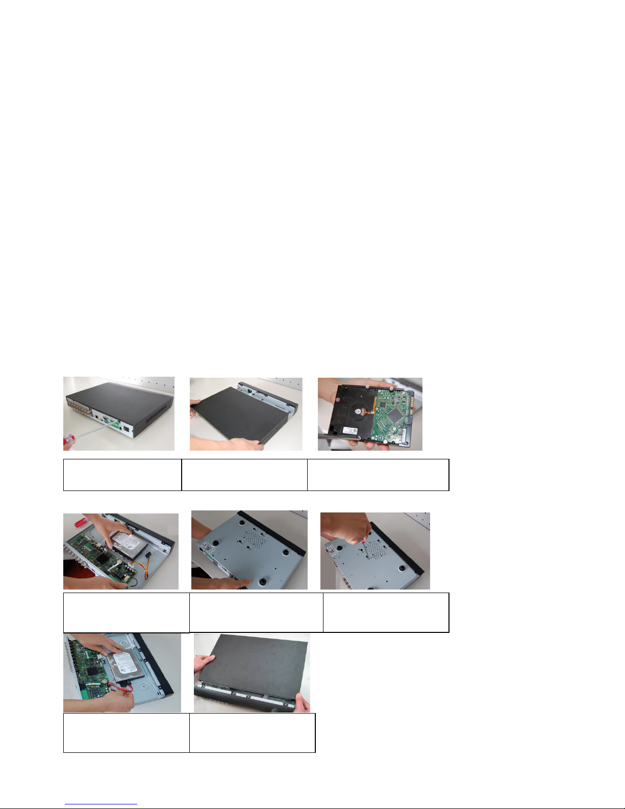
2.2 HDD Installation
If your DVR was ordered with a hard disk drive (HDD) preinstalled, please skip this step. The
G4-HDE series DVR may contain only one SATA HDD. If installing or upgrading, please use a
HDD of 7200rpm or higher. Please refer to the User’s Manual for recommended HDD brands
and models.
Please follow the instructions below to install/upgrade the HDD.
1. Remove the screws
4. Mount the HDD using the
four holes in the chassis.
7. Connect the SATA cable and
power cable.
2. Remove cover.
3. Loosely connect four screws to
5. Turn the DVR over.
8. Replace the cover.
6. Tighten the screws attaching
the HDD to the chassis.
3

In PTZ menu, shift PTZ control menu.
2.3 Front Panel
The front panel is shown as in Figure 1-1.
Figure 2-1
Please refer to the following table for front panel information.
Name Icon Function
Power button
Shift Shift
Up (1)
Down (4)
Left (2)
Right (3)
ESC ESC
Enter ENTER
Press and hold for three to five seconds to boot up or shut
down DVR.
When entering data, press to switch between numeric, upper
case, lower case and special characters.
Activate current control, modify setup, and then move up and
down
Increase or decrease number.
Assist function such as PTZ menu.
In text mode, input number 1 or 4.
Shift currently activated control.
In playback mode, click these buttons to control the playback
bar.
In text mode, input number 2 or 3.
Return to previous menu, or cancel current operation.
When in playback mode, click to restore real-time monitor
mode.
Select current operation
Go to default button
Go to menu
Record REC
Slow play (8)
Function Fn
Manually start or stop recording. Use with direction keys
or numeric keys to select the recording channel.
In playback mode cycle through slow play speeds
In text mode, input number 8
One-window monitor mode, click this button to display
assistant function: PTZ control and image color.
In numeric or text entry, delete the previous character
4
indication
indication
In motion detection setup, work with Fn and direction keys to
realize setup
In text mode, click to switch between numeric, upper case,
lower case and special characters
Fast forward
(7)
Play previous
(0)
Reverse/
Pause (6)
Play Next (9)
Play/Pause
(5)
USB port
Network
abnormal
HDD
abnormal
Record light Alarm Lit when system is recording.
IR Receiver IR Receives signal from the remote control.
Net
HDD
In playback mode, cycle through playback speeds
In text mode, input number 7
In playback mode, skip to previous file
In text mode, input number 0
In playback or pause mode, click for reverse playback
In reverse playback, click to pause playback
In text mode, input number 6
In playback mode, skip to next file
In menu or setup mode, go to the next field
In text mode, input number 9
In playback mode, click to pause
In pause mode, click to resume playback
In text mode, input number 5
Used for connection of USB storage device or USB mouse.
Lit when network error occurs or if there is no network
connection.
Lit when HDD error occurs or HDD capacity is below
specified threshold value.
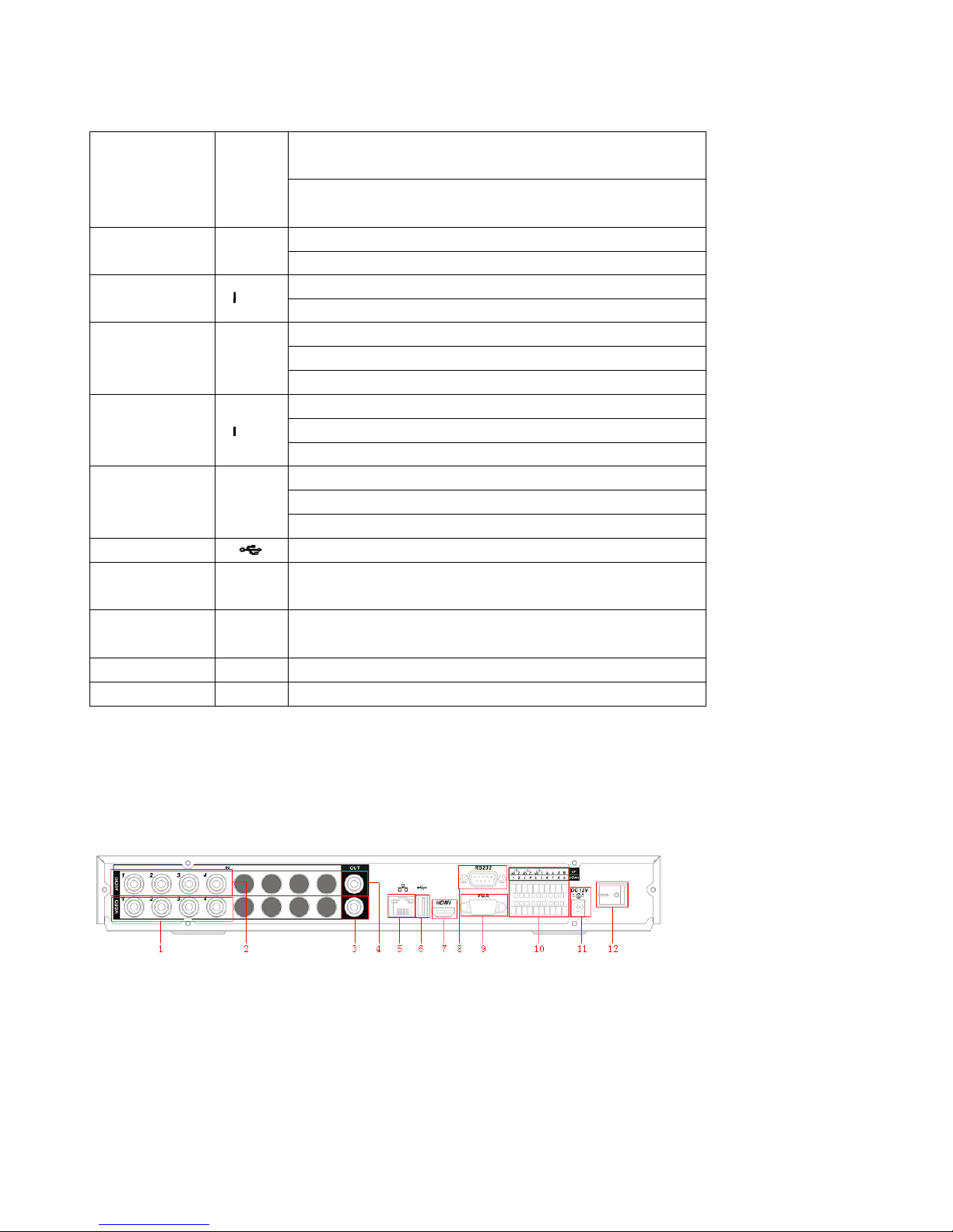
2.4 Rear Panel
The 4-ch rear panel is shown as below. See Figure 2-2.
Figure 2-2
5
The 8-ch rear panel is shown as below. See Figure 2-3.
Figure 2-3
The 16-ch real panel is shown as below. See Figure 2-4.
Figure 2-4
Please refer to the following table for detail information.
1 Analog video input
2 Audio input
3 Composite (BNC) video output
4 Audio output
5 Ethernet port
6 USB port
7 HDMI video port
8 RS-232 port
9 VGA video output
10 Alarm input, alarm output, RS-485 port
11 Power input port
12 Power switch
When connecting to the Ethernet port, use a straight through cable to connect to a switch or
router or use a crossover cable to connect directly to a PC.
6
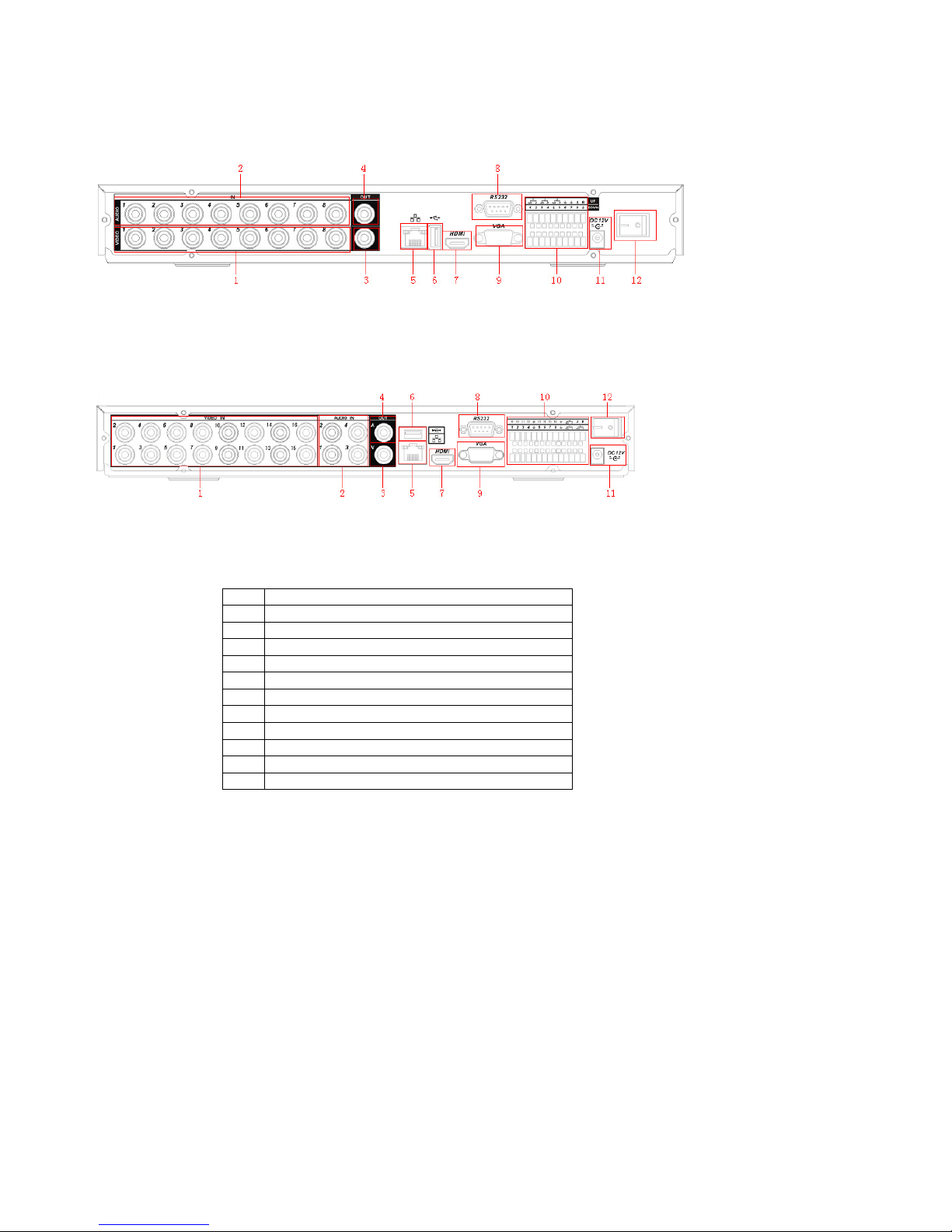
2.5 Connection Samples
Please refer to Figure 2-5 for connection samples.
Figure 2-5
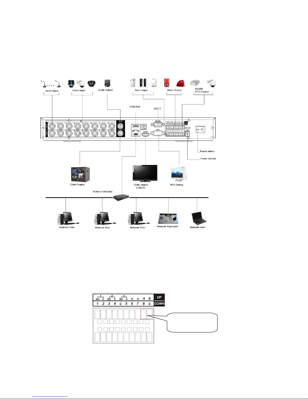
2.5 Alarm Input and Output Connection
There are two alarm input types for you to select: normal open (NO) and normal close (NC).
2.5.1 Alarm Input and Output Details
RS-485 A(+) B(-)
Connection port
Figure 2-6
7
 Loading...