

Page 1

Forensic NVR Quick Start Guide
Version 2.2.0
Page 2

i
Table of Contents
1 Hardware Installation and Connection..........................................................................1
1.1 Check Unpacked NVR........................................................................................1
1.2 About Front Panel and Rear Panel ..................................................................1
1.3 After Remove the Chassis .................................................................................1
1.4 HDD Installation...................................................................................................1
1.5 Front Panel...........................................................................................................2
1.6 Rear Panel ...........................................................................................................3
1.7 Connection Sample.............................................................................................3
1.8 Alarm Input and Output Connection.................................................................4
1.8.1 Alarm Input and Output Details.................................................................4
1.8.2 Alarm Input Port...........................................................................................5
1.8.3 Alarm Output Port........................................................................................5
2 Overview of Navigation and Controls............................................................................6
2.1 Login, Logout & Main Menu...............................................................................6
2.1.1 Login..............................................................................................................6
2.1.2 Main Menu....................................................................................................7
2.1.3 Logout ...........................................................................................................7
2.1.4 Auto Resume after Power Failure ............................................................8
2.2 Live Viewing .........................................................................................................8
2.3 PTZ Control..........................................................................................................9
2.4 PIP Setup ...........................................................................................................13
2.4.1 Video 1-4 PIP.............................................................................................13
2.4.2 4-window PIP mode..................................................................................14
2.5 Real-time Burning and CD Playback..............................................................15
2.6 Overlay Temperature/Humidity Information..................................................18
2.6.1 RS232 Mode ..............................................................................................18
2.6.2 RS485 Mode ..............................................................................................20
Page 3

ii
2.7 Backup ................................................................................................................22
2.8 CD Copy .............................................................................................................23
2.9 CD Verification...................................................................................................23
3 Web Operation................................................................................................................26
3.1 Network Connection..........................................................................................26
3.2 Login....................................................................................................................26
3.2.1 Real-time Monitor......................................................................................28
3.2.2 PTZ..............................................................................................................30
3.2.3 Color ............................................................................................................33
3.2.4 Picture Path and Record Path.................................................................33
Appendix Toxic or Hazardous Materials or Elements .....................................................35
Page 4

iii
Welcome
Thank you for purchasing our NVR!
This quick start guide will help you become familiar with our NVR in a very short time.
Before installation and operation, please read the following safeguard and warning carefully!
Important Safeguard and Warning
1.Electrical safety
All installation and operation here should conform to your local electrical safety codes.
We assume no liability or responsibility for all the fires or electrical shock caused by improper
handling or installation.
2.Transportation security
Heavy stress, violent vibration or water splash are not allowed during transportation, storage and
installation.
3.Installation
Keep upwards. Handle with care.
Do not apply power to the NVR before completing installation.
Do not place objects on the NVR.
4.Qualified engineers needed
All the examination and repair work should be done by the qualified service engineers.
We are not liable for any problems caused by unauthorized modifications or attempted repair.
5.Environment
The NVR should be installed in a cool, dry place away from direct sunlight, inflammable,
explosive substances and etc.
6. Accessories
Be sure to use all the accessories recommended by manufacturer.
Before installation, please open the package and check all the components are included:
Contact your local retailer ASAP if something is missing in your package.
7. Lithium battery
Improper battery use may result in fire, explosion, or personal injury!
When replace the battery, please make sure you are using the same model!
Page 5
1
1 Hardware Installation and Connection
Note: All the installation and operations here should conform to your local
electric safety rules.
1.1 Check Unpacked NVR
When you receive the NVR from the forwarding agent, please check whether there is any visible
damage. The protective materials used for the package of the NVR can protect most accidental
clashes during transportation. Then you can open the box to check the accessories.
Please check the items in accordance with the list. (Remote control is optional). Finally you can
remove the protective film of the NVR.
Note
Remote control is not a standard accessory and it is not included in the accessory bag.
1.2 About Front Panel and Rear Panel
For detailed information of the function keys in the front panel and the ports in the rear panel,
please refer to the User’s Manual included in the resource CD.
The model label in the front panel is very important; please check according to your purchase
order.
The label in the rear panel is very important too. Usually we need you to represent the serial
number when we provide the service after sales.
1.3 After Remove the Chassis
Please check the data cable, power cable, COM cable and main boar cable connection is secure
or not.
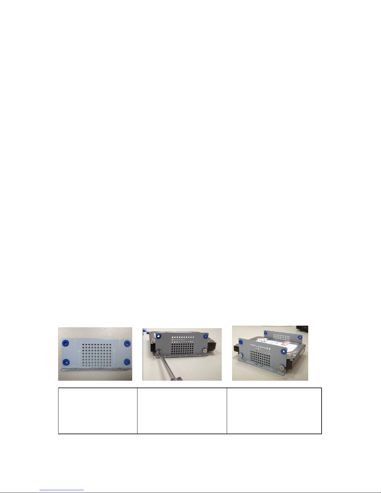
1.4 HDD Installation
You can refer to the User’s Manual for recommended HDD brand. Please follow the instructions
below to install hard disk. This series NVR has two SATA HDDs. Please use HDD of 7200rpm or
higher.
All the figurers listed below are for reference only. Slight difference may be found on the front or
rear panel.
1. Take the HDD bracket out
of the accessories bag and
then place the four gaskets to
the four holes. .
2. Place the HDD to the holes of
the bracket and then use the
screws to fix firmly.
3. Secure the brackets of the two
sides on the HDD.
Page 6
2
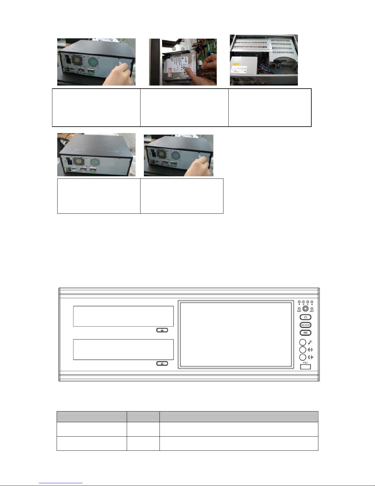
Important
z When there is a bracket, please make sure the installation direction of HDDs is the same.
z Please pay attention to the front cover. It adopts the vertical sliding design. You need to
push the clip first and then put down.
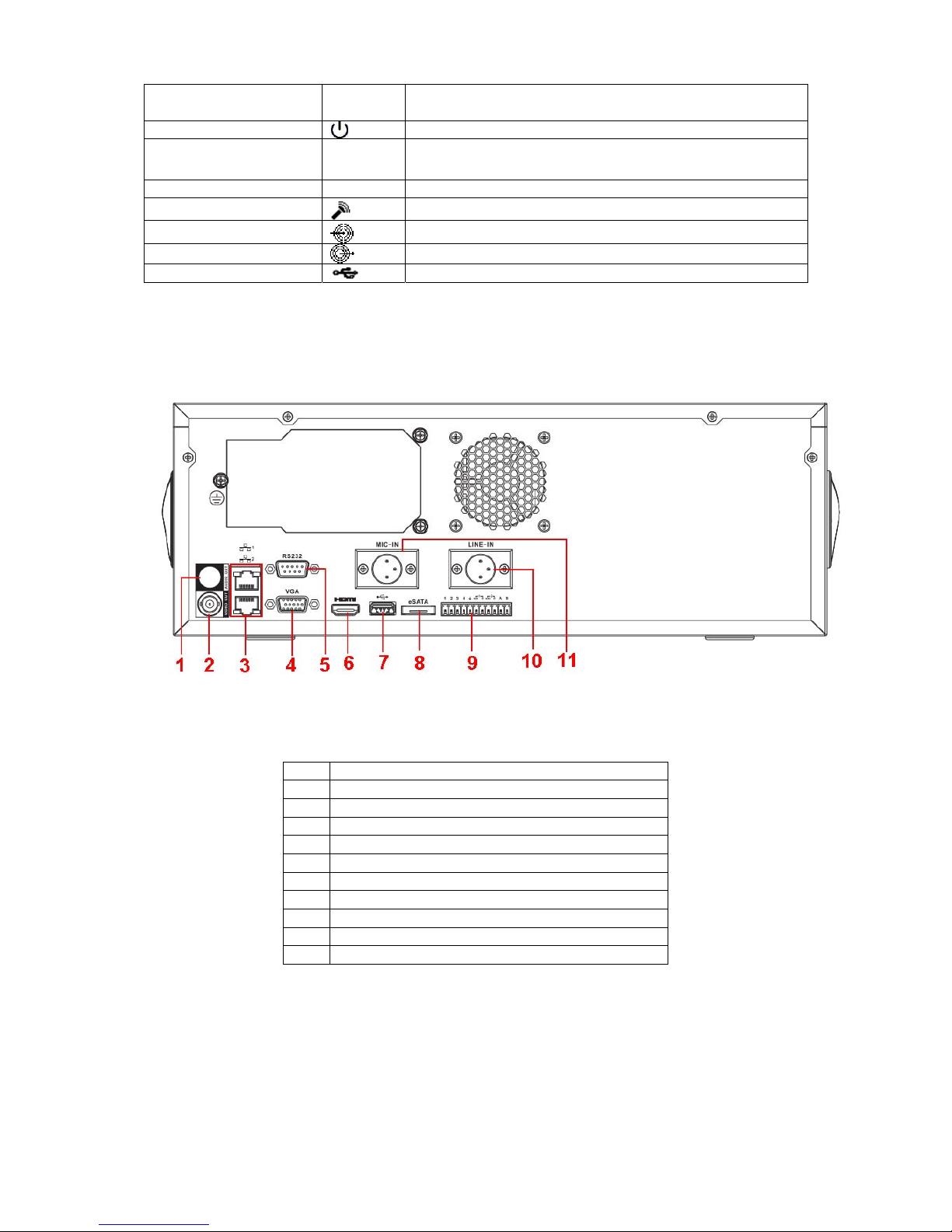
1.5 Front Panel
The front panel is shown as in Figure 1-1.
Figure 1-1
Please refer to the following sheet for front panel button information.
Button Name Icon Function
HDD record indicator
light
1-4
The corresponding HDD is recording when it is on.
Network abnormal
indicator light
NET
It is to alert you when network is abnormal or no
connection.
4. Unfasten the screws of the
rear and side panel of the device.
5. Use special data cable to
connect the HDD cable and power
cable.
6. Place the bracket in line with
the four holes of the device and
then use screws to fix from the
bottom.
7. Put the cover in accordance
with the clip and then place the
upper cover back.
8. Secure the screws in the
rear panel and the side panel.
Page 7
3
Remote control
indicator light
ACT
Remote control indicator light
Power indicator light
The light is on when power connection is OK.
Burning Start/stop
REC/ST
OP
z REC:Start burning.
z STOP:Stop burning.
Cancel ESC Exit
Microphone
Microphone port.
Line audio input
Line audio input port.
Line audio output
Line audio output port.
USB port
Connect to mouse, HDD and etc.
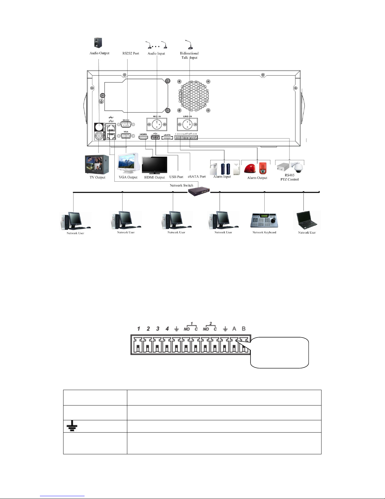
1.6 Rear Panel
The series NVR rear panel is shown as below. See Figure 1-2.
Figure 1-2
Please refer to the following sheet for detailed information.
1 Audio output
2 Video output
3 Network port
4 VGA output
5 RS232 port
6 HDMI port
7 USB port
8 eSATA port
9 Alarm input/alarm output/RS485 port
10 Line audio input port
11 Microphone port
When connect the Ethernet port, please use crossover cable to connect the PC and use the
straight cable to connect to the switcher or router.
1.7 Connection Sample
Please refer to Figure 1-3 for connection sample.
Page 8
4
Figure 1-3
1.8 Alarm Input and Output Connection
There are two alarm input types for you to select: normal open (NO) and normal close (NC).
1.8.1 Alarm Input and Output Details
Figure 1-4
You can refer to the following sheet for alarm input and output information.
1,2,3,4,
ALARM 1 to ALARM 4. The alarm becomes active in low voltage.
NO1 C1,NO2 C2
There are two groups of normal open activation output (on/off
button)
Earth cable.
485 A/B 485 communication port. They are used to control devices such as
PTZ. Please parallel connect 120TΩ between A/B cables if there are
too many PTZ decoders.
AB cable
connection
Page 9
5
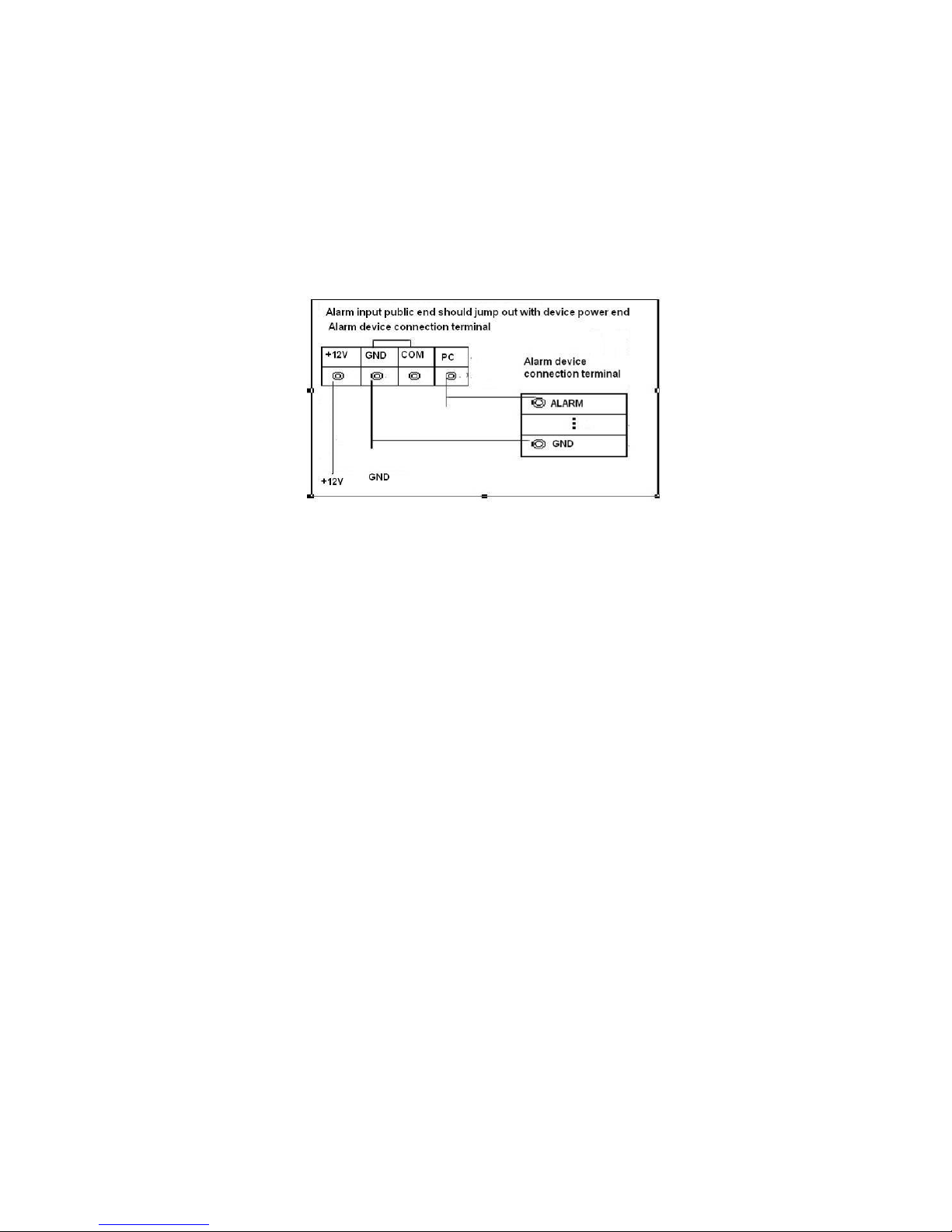
1.8.2 Alarm Input Port
Please refer to the following sheet for more information.
z Normal open or Normal close type.
z Please parallel connect COM end and GND end of the alarm detector (Provide external
power to the alarm detector).
z Please parallel connect the Ground of the NVR and the ground of the alarm detector.
z Please connect the NC port of the alarm sensor to the NVR alarm input(ALARM)
z Use the same ground with that of NVR if you use external power to the alarm device.
Figure 1-5
1.8.3 Alarm Output Port
z Provide external power to external alarm device.
z To avoid overloading, please read relay parameters sheet in the User’s Manual carefully.
z RS485 A/B cable is for the A/B cable of the PTZ decoder.
Page 10
6
2 Overview of Navigation and Controls
Before operation, please make sure:
z You have properly installed HDD and all the cable connections.
z The provided input power and the device power are matched.
z The external power shall be AC100~240V 50+2% Hz.
z Always use the stable current, if necessary UPS is a best alternative measure.
2.1 Login, Logout & Main Menu
2.1.1 Login
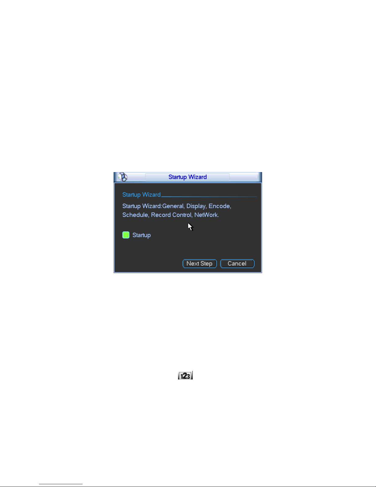
After system booted up, system pops up the startup wizard.
Click the Cancel button; you can go to the system login interface.
Click the Next Step button; you can go to the startup wizard interface. Here you can set the
system basic information. See Figure 2-1.
Figure 2-1
The system login interface is shown as in Figure 2-2.
System consists of four accounts:
z Username: admin. Password: admin. (administrator, local and network)
z Username: 888888. Password: 888888. (administrator, local only)
z Username: 666666. Password: 666666(Lower authority user who can only monitor, playback,
backup and etc.)
z Username: default. Password: default(hidden user)
You can use USB mouse, front panel, remote control (not included in the accessory bag) or
keyboard to input. About input method: Click
to switch between numeral, English character
(small/capitalized) and denotation.
Note:
For security reason, please modify password after you first login.
Continuous three times login failure will result in system alarm and six times login failure will
result in account lock!
Page 11
7
Figure 2-2
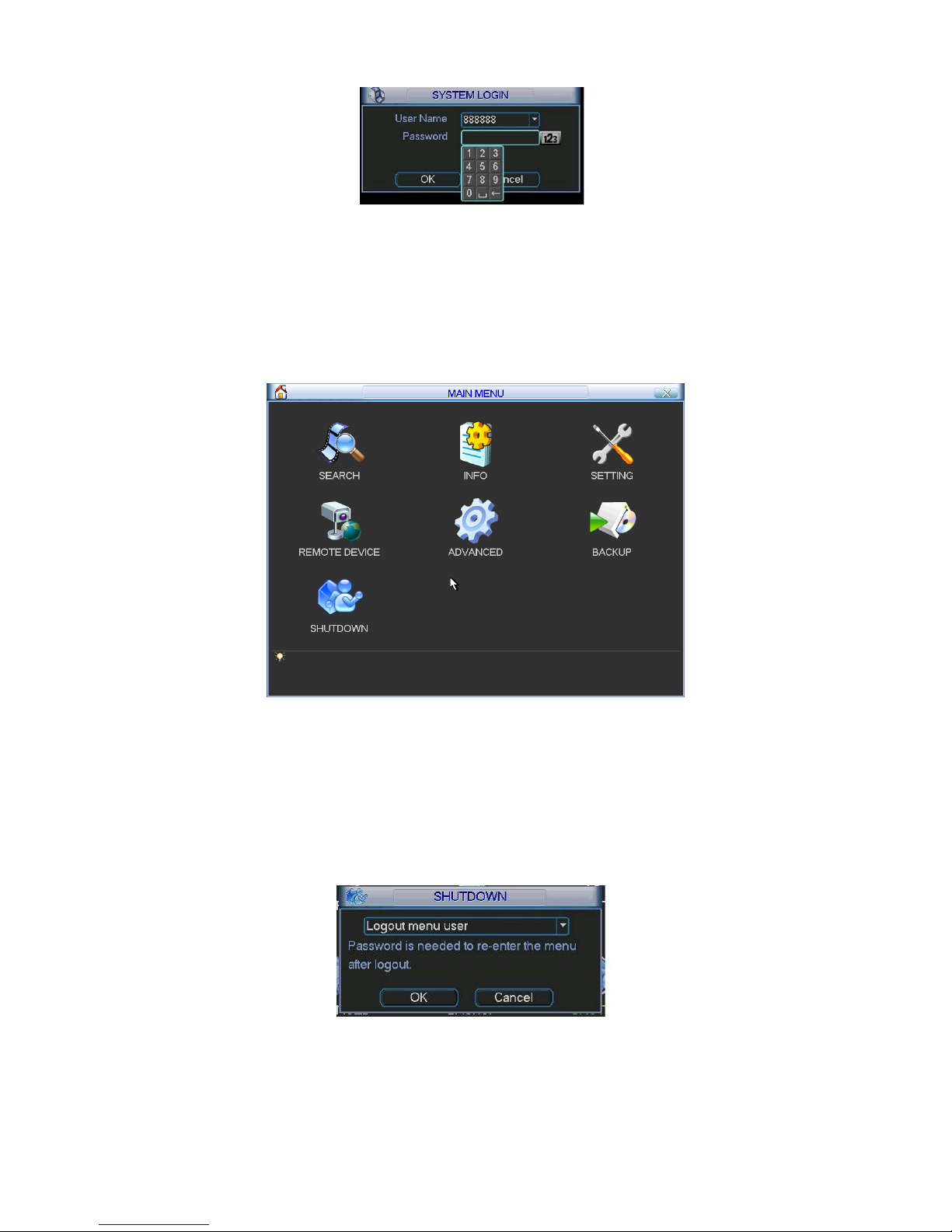
2.1.2 Main Menu
After you logged in, the system main menu is shown as below. See Figure 2-3.
There are total seven icons: search, Information, setting, backup, remote device, advanced and
shutdown. You can move the cursor to highlight the icon, and then double click mouse to enter
the sub-menu.
Figure 2-3
2.1.3 Logout
There are two ways for you to log out.
The first one is from menu option:
In the main menu, click shutdown button, you can see an interface is shown as below. See
Figure 2-4.
Figure 2-4
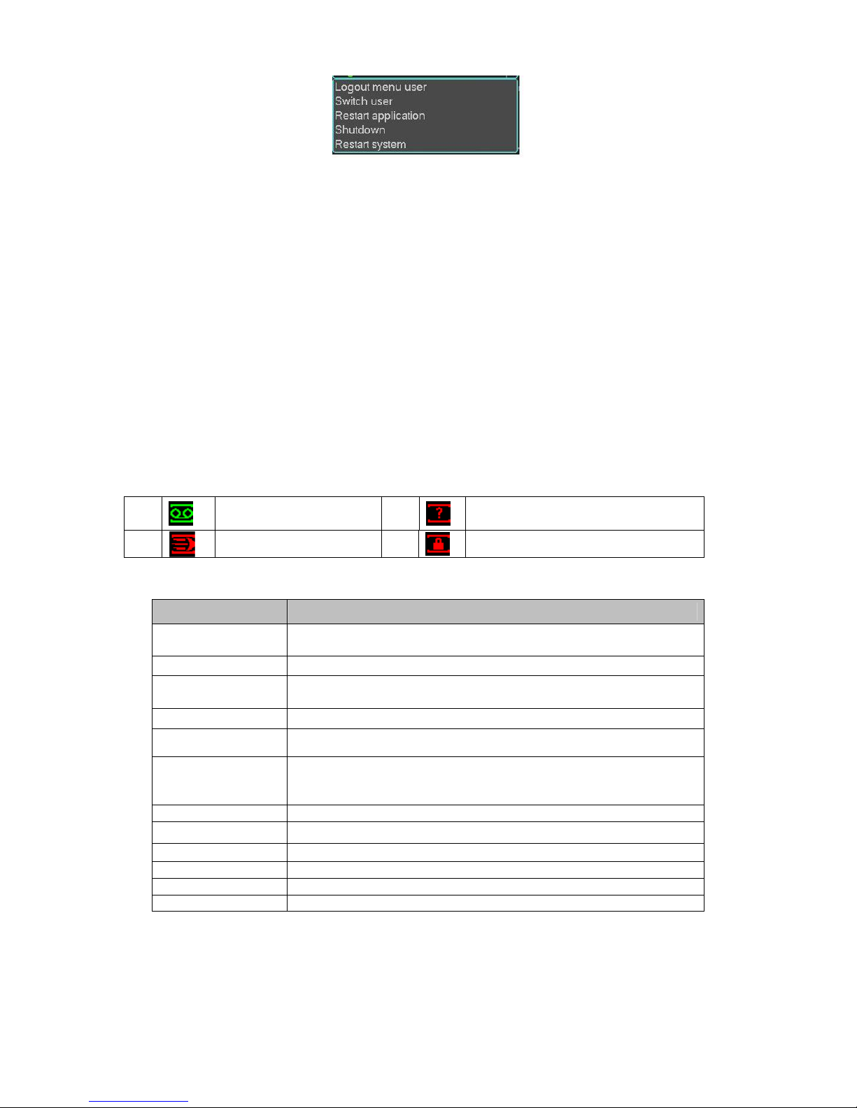
There are several options for you. See Figure 2-5.
Page 12
8
Figure 2-5
The other ways is to press power button on the front panel for at least 3 seconds, system will
stop all operations. Then you can click the power button in the front panel to turn off the NVR.
Please note, before you replace the HDD, do remember shutting down the device and unplug the
power cable.
2.1.4 Auto Resume after Power Failure
The system can automatically backup video and resume previous working status after power
failure.
2.2 Live Viewing
After you logged in, the system is in live viewing mode by default. You can see system date, time
and channel name. If you want to change system date and time, you can refer to general settings
(Main Menu->Setting->General). If you want to modify the channel name, please refer to the
display settings (Main Menu->Setting->Display). You can view there is a volume bar at the right
bottom corner. The volume bar becomes red when it is the max value.
Right click mouse, you can see system pops up the following menu. See Figure 2-6.
Please refer to the following sheet for detailed information.
Name Function
View 1
System displays in one-channel. You can select channel 1 to
channel 4.
View 4
System displays in 4-window.
View PIP
System displays in picture in picture mode. One picture is big
and one picture is small.
Pan/Tilt/Zoom
Set PTZ parameter and realize fast positioning.
Auto focus
Click it to adjust auto focus distance.
Color Setting
Set video hue, brightness, contrast, saturation and gain.
Please note you need to set a period here and the time format
shall be 24H.
Search Search record.
Record
Set record mode.
Remote device
It is the connected IPC setup.
Real-time burn Click to go to real-time burn interface.
Alarm output Set alarm output mode.
Main menu Go to main menu.
1
Recording status
3
Video loss
2
Motion detection
4
Camera lock
Page 13

9
Figure 2-6
2.3 PTZ Control
Before the operation, please go to Main Menu->Setting->Pan/Tilt/Zoom to set PTZ protocol first.
In the one-window surveillance mode, right click mouse (click “fn” Button in the front panel or
click AUX key in the remote control). Click Pan/Tilt/Zoom, the interface is shown as below.
See Figure 2-7.
Here you can set the following items:
z Step: value ranges fro 1 to 8.
z Zoom
z Focus
z Iris
Please click icon
and to adjust zoom, focus and iris.
Figure 2-7
In Figure 2-7, please click direction arrows (See Figure 2-8) to adjust PTZ position. There are
total 8 direction arrows.
Figure 2-8
3D Intelligent Positioning Key
Page 14

10
In the middle of the eight direction arrows, there is a 3D intelligent positioning key. See Figure
2-9.
X Please make sure your protocol supports this function and you need to use mouse to control.
Click this key, system goes back to the single screen mode. Drag the mouse in the screen to
adjust section size. The dragged zone supports 4X to 16X speeds. It can realize PTZ
automatically. The smaller zone you dragged, the higher the speed.
Figure 2-9
Here is a sheet for you reference.
Name Function
key
function Shortcut
key
Function
key
function Shortcut
Key
Zoom
Near
Far
Focus
Near
│_
Far
►
│
Iris
close
W
Open
f
Preset/ Patrol/Pattern/Scan
In Figure 2-7, please click the “set” button. The interface is shown as below. See Figure 2-10.
Here you can set the following items:
z Preset
z Tour
z Pattern
z Border
Figure 2-10
In X328H328H328H Figure 2-7, click page switch button, the interface is shown as in Figure 2-11.
Here you can activate the following functions:
z Preset
z Tour
z Pattern
z Auto scan
z Auto pan
z Flip
z Reset
z Page switch
Page 15

11
Figure 2-11
Note:
z Preset, tour and pattern all need the value to be the control parameter. You can define it as
you require.
z You need to refer to your speed dome user’s manual for Aux definition. In some cases, it
can be used for special process.
z The following setups are usually operated in the
X332H332H332HFigure 2-7, Figure 2-10 and Figure 2-11.
Preset Setup
In Figure 2-7, use eight direction arrows to adjust camera to the proper position.
In Figure 2-10, click preset button and input preset number. The interface is shown as in Figure
2-12.
Now you can add this preset to one tour.
Figure 2-12
Activate Preset
In Figure 2-11, please input preset number in the No. blank, and click preset button.
Patrol setup (Tour Setup)
In Figure 4-38, click patrol button. The interface is shown as in Figure 2-13.Input preset number
and add this preset to a patrol (tour). For each patrol (tour), you can input max 80 presets.
Figure 2-13
Page 16

12
Activate Patrol (tour)
In
X341H341H341H Figure 2-10, input patrol (tour) number in the No. blank and click patrol button
Pattern Setup
In Figure 2-10, click pattern button and then click “begin” button. The interface is shown as in
Figure 2-14. Then you can go to Figure 2-7 X to modify zoom, focus, and iris.
Go back to Figure 2-14 and click “end” button. You can memorize all these operations as pattern
1.
Figure 2-14
Activate Pattern Function
In
X346H346H346H Figure 4-39, input mode value in the No. blank, and click pattern button.
Auto Scan Setup
In
X347H347H347H Figure 4-38, click border button. The interface is shown as in X348H348H348H Figure 4-43.
Please go to
X349H349H349H X349H349H349HFigure 4-35, use direction arrows to select camera left limit
Then please go to
X350H350H350H Figure 4-43X and click left limit button
Repeat the above procedures to set right limit.
Figure 2-15
Activate Auto Scan
In Figure 2-11, click “Auto Scan” button, the system begins auto scan. Correspondingly, the auto
scan button becomes Stop button. Click stop button to terminate scan operation.
Flip
In Figure 2-11, click page switch button, you can see an interface is shown as below. See Figure
2-16. Here you can set auxiliary function. The aux value has relation ship with the Aux button of
the decoder.
Click page switch button again, system goes back to Figure 2-7.
Page 17

13
Figure 2-16
In Figure 2-16,click Page Switch button, you can go to Figure 2-17.(Please note only SD1 and
SD2 protocol can go to the following interface.)
The direction button here ti to control the speed dome menu. The displayed button here may vary
due to different protocol. The button is grey if current protocol does not support this function. Use
up/down button to switch between menu items and use left/right button to change setup. Click
enter/exit menu button to go to or exit speed dome menu. Click Page Switch button, system goes
back to Figure 2-7.
Figure 2-17
2.4 PIP Setup
2.4.1 Video 1-4 PIP
You can view different channels on the PIP mode. You can follow the steps listed below.
a) From main menu->setting->general, check the navigation bar to enable navigation function.
Close general interface and then left click mouse on the preview interface, you can see an
interface shown as in Figure 2-18.
Figure 2-18
b) In Figure 2-18, click to set a mode and then click . Now system goes to PIP mode.
Tips:
z One the preview interface, right click mouse and then select View PIP mode, then click
on Figure 2-18. You can go to PIP mode.
Page 18

14
z The PIP mode uses one channel as the main window. You can select channel 1/23/4
as the main picture.
c) On the PIP interface, click
at the top left corner to select a channel you want
to display and then click
to save. In mode 1, you can select 2/3/4 as the PIP mode.
Now you can see an interface shown as in Figure 2-19.You can use mouse to drag the PIP
picture to the proper position and drag mouse to zoom in or zoom out.
Figure 2-19
Note
z
: The grey highlighted channel is the main channel. The white channel is the
PIP channel and black channel is the current selected channel.
z On the PIP mode, the volume bar is the mixed audio. For mode 1 to mode 4, system can
mix the audio of the main interface and the PIP interface. It is the audio of the PIP preview
and record audio.
2.4.2 4-window PIP mode
You can view 4-window on the PIP mode. You can follow the steps listed below.
a) From main menu->setting->general, check the navigation bar to enable navigation function.
Close general interface and then left click mouse on the preview interface, you can see an
interface shown as in Figure 2-20.
Figure 2-20
b) In Figure 2-20, click
to set a mode and then click . Now system goes to 4-window
PIP mode.
Page 19

15
c) On the PIP interface, click at the top left corner to select a channel you want to
display. You can select
to set mixed audio and then click to save. See Figure
2-21.
Figure 2-21
Note
z
: can only be displayed on the first channel and can only be displayed on
the second channel. You can click
at the top left corner to set mixed audio. P1 is the
mixed audio of channel 1 and channel 3. P2 is the mixed audio of channel 2 and channel 4.
During the preview mode, you can not select P1 and P2 at the same time. It is the output
audio of the preview interface, that is to say it is the audio of the channel P on the PIP mode.
z You can use mouse to drag the PIP picture to the proper position and drag mouse to zoom
in or zoom out.
2.5 Real-time Burning and CD Playback
This series product can burn real-time video to the CD for future reference. You can click the
REC/STOP at the front panel to start or stop burning. Or you can go to the burning interface
via the right-click mouse menu. Please follow the steps listed below.
a) One the preview interface, right click mouse and then select real-time burning. You can
see an interface shown as in Figure 2-22. Please note the record channel needs to set
as P (PIP), otherwise, you can not see the three setup buttons on the right pane.
Page 20

16
Figure 2-22
Tips
z Click the REC/STOP at the front panel; you can go to burning interface. Click
REC/STOP for a short time, you can begin or pause burning. If you click REC/STOP for
a long time during the burning process, you can stop burning operation.
z On the left-click mouse menu, select main menu and then click Backup button. Click Burning
button, you can go to Figure 2-22 too.
b) Select a device from the dropdown list and then select a record channel.
c) Now you can set burn setup, mark setup and etc. Please note you can not set during the
burning process.
Click Settings button, you can see the following interface. See Figure 2-23.
Here you can set interrogation time and resolution. Click Save button. System can calculate
the corresponding channel bit stream according to you input information and the CD space.
Figure 2-23
Click Burn setup, system pops up the following interface. See Figure 2-24.Please input
record password twice to confirm and check the corresponding box here to select information
you want to overlay on the burning record. Check the Check button at the bottom of the
Page 21

17
interface, system can auto generate verification information during the burning process. You
can use the verification information to check the data has been tampered with or not. For
detailed CD verification information, you can view chapter 2.9.
Figure 2-24
You can click Mark setup button if you want to mark during the burning process.
d) Now you can click Start Sync burning on Figure 2-22 to begin burning.
Note
z Start sync burning: You can select one or more CD to burning at the same time. System
burns the same data. System stops burning when it finishes burning. Or you can stop
manually.
z Start tour burning: You need to select several CD to begin circle burning. System begins
burning from the first CD and then auto goes to the second CD until it finishes all CD
burning.
z Change CD: During the CD burning process, you can click it to replace CD manually.
System pops up current CD and then you can input a new one. System begins burning
data from the previous 5 minutes of the previous CD so that there is no missing data
between these two CDs.
z Pause: During the burning process, you can pause current burning if the court is
adjournment. Click continue button, you can begin burning again and all data is on the
same CD.
e) Click OK button on the pop-up dialog box, after you complete the burning.
CD Playback
This function is for you to verify the real-time burning data. You can check the real-time
burning data and backup data.
On the preview interface and then right click mouse, select Search.
Or you can go to the search interface, from main menu-search interface.
In Search interface (Main menu->Search), select Play from CD from the dropdown list and
then click file list switch button
. You can see an interface shown as in Figure 2-25. Here
you can view file list from the CD. Double click a file name, you can playback a file.
Page 22

18
Figure 2-25
Important
Real-time burning and CD playback can not be operated at the same time since these two
functions are both for CD-ROM.
2.6 Overlay Temperature/Humidity Information
After you connect device to temperature and humidity device, you need to set corresponding
parameters so that you can overlay temperature humidity information on the monitor video or
record file. You can connect the temperature humidity device via the RS232.
2.6.1 RS232 Mode
a) Set COM protocol
On the preview interface, right click mouse and then select main menu, from main menu-
>advanced->card overlay. The interface is shown as in Figure 2-26.
Figure 2-26
Page 23

19
Now you can set Sniffer mode as COM and protocol is RC or other protocols. Click COM setting
button, you can see COM setup interface. See Figure 2-27.
Now you can set RS232 information. The COM function is the protocol and the baud rate, data
bit, stop bit shall be the same with the temperature humidity device. Click Save to save you setup.
Figure 2-27
In Figure 2-26, select PIP channel from the dropdown list and then click overlay setup button,
you can see the following interface. See Figure 2-28.
Check the preview or monitor mode after T/H (Temperature/humidity) and then click Set button to
set overlay position. Click Save button to exit.
Figure 2-28
Tips
z In Figure 2-28, click Set button, you can set overlay position.
z Each channel can set its own overlay information. The channel 1-4 encode overlay position
is corresponding to the overlay effect of its own channel during the preview. The PIP overlay
position is corresponding to the 4-window and PIP preview overlay effect.
Page 24

20
z Preview means you can overlay temperature humidity information on local preview window.
Monitor means you can overly temperature humidity information on the record file so that
you can view it when playback.
b) Connect the temperature humidity device to the device via the RS232.
Connect the A/B cable of the temperature humidity device to the A/B cable of the 485 to 232 tool.
Connect the RS232 port of the 485 to 232 tool to the RS232 port of the device.
Note:
z Right now the temperature humidity sniffer mode adopts RS485 port. In case it may affect
the RS485 PTZ control of the device, the temperature humidity output shall go through a
RS485-232 tool so that you can connect the RS232 to the RS232 port of the device.
z For some series RS485-232 tool , it may need power supplying. Otherwise, the data may not
stable or there is no data at all. In this situation, device can not overlay information.
2.6.2 RS485 Mode
a) Set COM protocol
On the preview interface, right click mouse and then select main menu, from main menu-
>advanced->card overlay. The interface is shown as in Figure 2-26.
Figure 2-29
Now you can set Sniffer mode as COM and protocol is RC or other protocols. Click COM setting
button, you can see COM setup interface. See Figure 2-27.
Now you can set COM information. The COM function is the PTZ matrix and the baud rate, data
bit, stop bit shall be the same with the temperature humidity device. Click Save to save you setup.
Page 25

21
Figure 2-30
In Figure 2-26, select the PIP channel (channel P) to overlay temperature/humidity information.
Click overlay setup button, you can see the following interface. See Figure 2-28.
Check the preview or monitor mode and then click Save button.
Figure 2-31
Tips
z In Figure 2-28, click Set button, you can set overlay position. You need to select channel P
(PIP) to overlay information.
z Preview means you can overlay temperature humidity information on local preview window.
Monitor means you can overly temperature humidity information on the record file so that
you can view it when playback.
b) Connect temperature humidity device to the NVR
Connect the A2 and Y2 cable at the rear panel of the NVR to the A (or “+”) cable of the
temperature humidity device.
Connect the B2 and Z2 cable at the rear panel of the NVR to the B (or “-”) cable of the
temperature humidity device.
Page 26

22
2.7 Backup
NVR support USB device backup and network download. Here we introduce USB backup.
You can refer to User’s Manual Chapter 5 Web Operation for network download backup
operation.
a) On the preview interface, right click mouse and then click main menu.
b) Click backup button, the interface is shown as below. See Figure 2-32.
Figure 2-32
c) Select a backup device and then click Backup button. System pops up the following
interface. See Figure 2-33.
d) Select backup device and then set channel, file start time and end time. Click add
button, system begins search. All matched files are listed below. System automatically
calculates the capacity needed and remained.
Important
If you want to backup PIP file, the channel shall be set as P.
Figure 2-33
Page 27

23
e) system only backup files with a √ before channel name. You can use Fn or cancel
button to delete √ after file serial number. Click backup button, you can backup
selected files. There is a process bar for you reference. When the system completes
backup, you can see a dialogue box prompting successful backup.
Note
The file name format usually is: SN_CH+channel number+time Y+M+D+H+M+S. In the file
name, the YDM format is the same as you set in general interface. (Main Menu ->Setting -
>General).File extension name is .dav.
2.8 CD Copy
This function allows you to copy one CD contents to another CD. Please follow the steps
listed below.
On the preview interface, right click mouse and then click main menu.
Click backup button, you can go to backup interface.
Click CD copy button at the bottom of the interface. You can go to the following interface.
See Figure 2-34. You can see some reference information at the right bottom corner of the
interface. You can see the corresponding dialogue box after the copy operation.
Figure 2-34
Note
z During the backup process, system automatically playback current file.
z Click
at the left bottom corner during the copy process, you can copy video data only.
z During the copy process, you can implement fast forward/backward, pause and resume
function.
2.9 CD Verification
If you have checked the verification function when you burn CD, you can use it to see the data
has been tampered with or not. Please follow the steps listed below. See
Page 28

24
On preview window, right click mouse and then select real-time burning. Click the burn setup
button, you can go to the following interface. See Figure 2-35.Check the verification box at the
bottom of the interface.
Figure 2-35
After the burning operation, you can check the CD is original or not.
On the preview interface, right click mouse and then select main menu. Click Backup button.
Check CD Check button. You can see CD check interface shown as below. See Figure 2-36.
Figure 2-36
Select a CD from the dropdown list at the bottom of the interface and then check the file(s) you
want to verify.
Now system automatically begins check operation. You can see the check result on the right
column. System displays as success if the file is original. It is shown as failed if the file has no
data, or some data is missing or the data has been tampered with. See Figure 2-37.
Page 29

25
Figure 2-37
Page 30

26
3 Web Operation
There might be slightly difference in the interface due to different series.
3.1 Network Connection
Before web operation, please check the following items:
z Network connection is right
z NVR and PC network setup is right. Please refer to network setup(main menu->setting-
>network)
z Use order ping ***.***.***.***(* NVR IP address) to check connection is OK or not. Usually
the return TTL value should be less than 255.
z Open the IE and then input NVR IP address.
z System can automatically download latest web control and the new version can overwrite
the previous one.
z If you want to un-install the web control, please run uninstall webrec2.0.bat. Or you can go to
C:\Program Files\webrec to remove single folder. Please note, before you un-install, please
close all web pages, otherwise the un-installation might result in error.
3.2 Login
Open IE and input NVR address in the address column. For example, if your NVR IP is
10.10.3.16, then please input http:// 10.10.3.16 in IE address column. See Figure 3-1.
Figure 3-1
System pops up warning information to ask you whether install webrec.cab control or not. Please
click yes button.
If you can’t download the ActiveX file, please modify your settings as follows. See Figure 3-2.
Input your IP
address here.
Page 31

27
Figure 3-2
After installation, the interface is shown as below. See Figure 3-3.
Please input your user name and password.
Default factory name is admin and password is admin.
Then you can select the login mode: LAN and WAN.
Note: For security reasons, please modify your password after you first login.
Figure 3-3
After you logged in, you can see the main window. See Figure 3-6.
This main window can be divided into the following sections.
z Section 1: there are five function buttons: configuration, search, alarm, about, log out.
z Section 2: there are channel number and three function buttons: start dialog and local play,
refresh.
Page 32

28
z Section3: there are PTZ (chapter 3.2.2), color (chapter3.2.3) button and you can also select
picture path and record path.
z Section 4:real-time monitor window. Please note current preview window is circled by a
green rectangle zone.
z Section 5: Here you can view window switch button. You can also select video priority
between fluency or real-time.
System monitor window switch supports full screen/1-window/4-window/6-window/8-
window/9-window/13-window/16-window/20-window/25-window/36-window. See Figure
3-4.
Figure 3-4
Preview window switch. System support 1/4/8/9/16-window real-time preview. Please you
need to have the proper rights to implement preview operation. You can not preview if you
have no right to preview the either channel. See Figure 3-5. Please note this series device
does not support this function.
Figure 3-5
Figure 3-6
3.2.1 Real-time Monitor
In section 2, left click the channel name you want to view, you can see the corresponding video
in current window.
Section1
Section 2
Section 3
Section 5
Section 4
Page 33

29
On the top left corner, you can view device IP, channel number, network monitor bit stream. See
Figure 3-7.
Figure 3-7
On the top right corer, there are six unction buttons. See Figure 3-8.
Figure 3-8
z 1: Digital zoom: Click this button and then left drag the mouse in the zone to zoom in. right
click mouse system restores original status.
z 2: Change show mode: resize or switch to full screen mode.
z 3: Local record. When you click local record button, the system begins recording and this
button becomes highlighted. You can go to system folder RecordDownload to view the
recorded file.
z 4: Capture picture. You can snapshoot important video. All images are memorized in system
client folder \download\picture (default).
z 5: Audio :Turn on or off audio.(It has no relationship with system audio setup )
z 6: Close video.
Please refer to Figure 3-9 for main stream and extra stream switch information.
Figure 3-9
Open All
You can click it to open all channels.
Refresh
You can use button to refresh camera list.
Start Dialogue
1 2 3 4 5 6
1 2 3
Page 34

30
You can click this button to enable audio talk. Click 【▼】 to select bidirectional talk mode.
There are four options: DEFAULT,G711a,G711u and PCM.
Please note, the audio input port from the device to the client-end is using the first channel audio
input port. During the bidirectional talk process, system will not encode the audio data from the 1-
channel.
Local Play
The Web can playback the saved (Extension name is dav) files in the PC-end.
Click local play button, system pops up the following interface for you to select local play file. See
Figure 3-10.
Figure 3-10
3.2.2 PTZ
Before PTZ operation, please make sure you have properly set PTZ protocol. (Please refer to
User’s Manual Setting-> Pan/Tilt/Zoom).
Click PTZ button, the interface is shown as in Figure 3-11.
Page 35

31
Figure 3-11
3.2.2.1 Direction key and 3D positioning key
In Figure 7-10, there are eight direction keys.
In the middle of the eight direction keys, there is a 3D intelligent positioning key.
Click 3D intelligent positioning key, system goes back to the single screen mode. Drag the
mouse in the screen to adjust section size. It can realize PTZ automatically.
3.2.2.2 Speed
System supports eight-level speed. You can select from the dropdown list. Speed 2 is faster than
speed 1.
3.2.2.3 Zoom/Focus/Iris
Here is a sheet for you reference.
Name Function
key
Function Function
key
Function
Zoom
Near
Far
Focus
Near
Far
Iris
close
Open
In Figure 3-11, click PTZ setup button you can see the following interface. See Figure 3-12.
You can click this icon to
display or hide the PTZ
control platform.
3D Intelligent Positioning
Key
Page 36

32
Figure 3-12
3.2.2.4 Auto Scan
In Figure 3-12, move the camera to you desired location and then click left limit button.
Then move the camera again and then click right limit button to set a right limit.
3.2.2.5 Pattern
In Figure 3-12, you can input pattern value and then click start record button to begin PTZ
movement. Please go back to Figure 7-11 to implement camera operation. Then you can click
stop record button. Now you have set one pattern.
3.2.2.6 Preset
In Figure 3-12, move the camera to your desired location and then input preset value. Click add
button, you have set one preset.
3.2.2.7 Auto tour
In Figure 3-12, input auto tour value and preset value. Click add button, you have added one
preset in the tour.
Repeat the above procedures you can add more presets in one tour.
3.2.2.8 Assistant
You can select the assistant item from the dropdown list. See Figure 3-13.
3.2.2.9 Matrix
This series product supports matrix extension function. You can control the video input and
output switch
3.2.2.10 Light and wiper
If your PTZ protocol supports the light and wiper control function. You can enable/disable the
light or the wiper.
Page 37

33
Figure 3-13
3.2.3 Color
Click color button in section 3, the interface is shown as Figure 3-14.
Here you can select one channel and then adjust its brightness, contrast, hue and saturation.
(Current channel border becomes green).
Or you can click default button to use system default setup.
Figure 3-14
3.2.4 Picture Path and Record Path
Click more button in Figure 3-14, you can see an interface is shown as in Figure 3-15.
Figure 3-15
Click the record item; you can see there are two options: DAV/ASF.
Click picture path button, you can see an interface is shown as in Figure 3-16.
Please click choose button to modify path.
Page 38

34
Figure 3-16
Click record path button, you can see an interface is shown as in Figure 3-17.
Please click choose button to modify path.
Figure 3-17
Click reboot button, system pops up the following dialogue box. See Figure 3-18.
Please click OK to reboot.
Figure 3-18
If there is local use logged in the system menu, or the Web logged in user has no right to reboot
the device system pops up a dialogue box to alert you.
For detailed operation information, please refer to the User’s Manual included in the
resources CD.
Page 39

35
Appendix Toxic or Hazardous Materials or Elements
Toxic or Hazardous Materials or Elements
Component
Name
Pb Hg Cd Cr VI PBB PBDE
Sheet
Metal(Case)
○ ○ ○ ○ ○ ○
Plastic Parts
(Panel)
○ ○ ○ ○ ○ ○
Circuit Board ○ ○ ○ ○ ○ ○
Fastener ○ ○ ○ ○ ○ ○
Wire and
Cable/AC
Adapter
○ ○ ○ ○ ○ ○
Packing
Material
○ ○ ○ ○ ○ ○
Accessories ○ ○ ○ ○ ○ ○
Note
O: Indicates that the concentration of the hazardous substance in all homogeneous materials in
the parts is below the relevant threshold of the SJ/T11363-2006 standard.
X: Indicates that the concentration of the hazardous substance of at least one of all
homogeneous materials in the parts is above the relevant threshold of the SJ/T11363-2006
standard. During the environmental-friendly use period (EFUP) period, the toxic or hazardous
substance or elements contained in products will not leak or mutate so that the use of these
(substances or elements) will not result in any severe environmental pollution, any bodily injury or
damage to any assets. The consumer is not authorized to process such kind of substances or
elements, please return to the corresponding local authorities to process according to your local
government statutes.
Note
z For detailed operation introduction, please refer to our resource CD included in your
package for electronic version of the User’s Manual.
z Slight difference may be found in user interface.
z All the designs and software here are subject to change without prior written notice.
z All trademarks and registered trademarks mentioned are the properties of their
respective owners.
z If there is any uncertainty or controversy, please refer to the final explanation of us.
z Please visit our website for more information.
 Loading...